

Page 1

MODEL NUMBER
MCS-H-S12
SERIAL NUMBER
DATE OF PURCHASE
12 GPM HYDRAULIC CHAINSAW
OPERATOR’S MANUAL
Revision 2017-06
MAXCUT INC.
MADE IN U.S.A. WWW.MAXCUTINC.COM
111 East 34th Street
South Chicago Heights, Illinois
Page 2

MAXCUT STEALTH-12 OPERATOR’S MANUAL
TABLE OF CONTENTS
CHAPTER TITLE PAGE
1. SAFETY ......................................................................................................................................... 4
1.1. INTRODUCTION ................................................................................................................... 4
1.2. SAFETY DEFINITIONS ........................................................................................................ 4
1.3. POWER SOURCE AND CHAINSAW SAFETY LABELS ................................................. 4
1.4. CHAINSAW SAFETY PRECAUTIONS .............................................................................. 4
2. SPECIFICATIONS ........................................................................................................................ 6
2.1. INTRODUCTION ................................................................................................................... 6
2.2. TECHNICAL DATA............................................................................................................... 6
2.3. RECOMMENDED HYDRAULIC OIL................................................................................... 6
2.4. NAMEPLATE AND SERIAL NUMBER TAG ..................................................................... 7
3. PRE-OPERATION INSPECTION AND SET-UP ....................................................................... 7
3.1. CHECKING THE SYSTEM HYDRAULICS ........................................................................ 7
3.2. CHECKING THE WATER SUPPLY .................................................................................... 8
3.3. INSPECTION AND INSTALLATION OF THE DRIVE SPROCKET................................. 9
3.4. INSPECTION AND INSTALLATION OF THE GUIDE BAR ........................................... 10
3.5. INSPECTION AND INSTALLATION OF THE CHAIN .................................................... 11
3.6. TENSIONING THE CHAIN ................................................................................................. 12
3.7. BREAKING IN A NEW CHAIN .......................................................................................... 13
4. OPERATION ............................................................................................................................... 13
4.1. PLANNING THE CUT ......................................................................................................... 13
4.2. CUTTING PROCEDURE .................................................................................................... 13
4.3. SHUTTING DOWN AND STORING THE SAW ............................................................... 14
5. MAINTENANCE .......................................................................................................................... 15
5.1. GENERAL MAINTENANCE RULES ................................................................................ 15
5.2. GUIDE BAR MAINTENANCE ............................................................................................ 15
5.3. CHAIN MAINTENANCE ..................................................................................................... 15
5.4. POWERHEAD MAINTENANCE ........................................................................................ 16
MAXCUT INC. Page 2 of 31 MADE IN U.S.A.
Page 3

MAXCUT STEALTH-12 OPERATOR’S MANUAL
6. FACTORS AFFECTING CHAIN LIFE ...................................................................................... 16
6.1. HOW DIAMOND SEGMENTS WORK .............................................................................. 16
6.2. MATERIAL FACTORS AFFECTING CHAIN LIFE .......................................................... 17
6.3. OPERATIONAL FACTORS AFFECTING CHAIN LIFE .................................................. 18
6.4. CHAIN END-OF-LIFE MODES .......................................................................................... 19
7. TROUBLESHOOTING ............................................................................................................... 20
8. PARTS LISTS ............................................................................................................................. 23
8.1. PARTS LIST - FRAME ASSEMBLY..................................................................................... 24
8.2. PARTS LIST – COVER ASSEMBLY .................................................................................... 26
8.3. PARTS LIST – HANDLE AND HOSE ASSEMBLIES......................................................... 27
8.4. PARTS LIST – SCRENCH TOOL ......................................................................................... 29
LIMITED PRODUCT WARRANTY ................................................................................................... 30
MAXCUT INC. Page 3 of 31 MADE IN U.S.A.
Page 4

MAXCUT STEALTH-12 OPERATOR’S MANUAL
1. SAFETY
1.1. INTRODUCTION
The MaxCut Stealth-12 is a sleek, mighty, and technologically advanced tool that
efficiently cuts concrete, brick, decorative stone, and utility pipe. The powerful hydraulic
motor facilitates cutting of precise, square corners up to 25‖ (64 cm) deep. We
engineered the Stealth-12 with the end user in mind to deliver an ergonomic saw with
optimal balance. The hose management guide and light weight design help to reduce
operator fatigue. However, even a well-designed and well-built saw can malfunction or
become hazardous in the hands of an inexperienced and/or untrained user. Therefore,
read this manual thoroughly before operating your saw to provide maximum safety for
all operating personnel, and to get the maximum benefit from your equipment.
1.2. SAFETY DEFINITIONS
A safety message alerts you to potential hazards which could injure you or others or
cause property damage. The safety messages or signal words for product safety signs
are DANGER, WARNING, and CAUTION. Each safety message is preceded by a
safety alert symbol and is defined as follows:
DANGER: Indicates an imminently hazardous situation which, if not avoided, will cause
death or serious injury. This safety message is limited to the most extreme situations.
WARNING: Indicates a potentially hazardous situation which, if not avoided, could
result in death or serious injury.
CAUTION: Indicates a potentially hazardous situation which, if not avoided, may result
in minor or moderate injury. It may also be used to alert against unsafe practices that
may result in property-damage-only accidents.
1.3. POWER SOURCE AND CHAINSAW SAFETY LABELS
These labels warn you of potential hazards that could cause injury. Read them carefully.
If a label comes off or becomes illegible, contact MaxCut, Inc. for a replacement,
www.maxcutinc.com.
1.4. CHAINSAW SAFETY PRECAUTIONS
1.4.1. Only trained personnel shall operate the saw or perform repairs. A trained
person is one who has read and thoroughly understands this instruction
manual and related equipment manuals and, through training and experience,
has shown knowledge regarding the safe operational procedures.
1.4.2. Sawing area must be kept clear of unauthorized personnel at all times. Place
barricades or secure the area with signs and a roped boundary to prevent
injury.
1.4.3. Never use the saw in an explosive atmosphere and/or near combustible
material that could be ignited by a spark.
1.4.4. DO NOT use the saw if it shows any signs of damage. DO NOT use the saw
if the chain continues to rotate when the power-activating trigger lever is
released.
MAXCUT INC. Page 4 of 31 MADE IN U.S.A.
Page 5

MAXCUT STEALTH-12 OPERATOR’S MANUAL
1.4.5. The chainsaw cover provides protection against contact with moving parts,
ejected debris, broken chain, thrown water, and concrete slurry. Never run
the saw without the cover in place.
1.4.6. Never allow anyone to stand in front of, or in line with the chain forward of the
guard.
1.4.7. Always use safety footwear, a snug fitting wet suit, safety goggles or face
shields, and hearing and head protection devices. Safety shoes MUST
provide good footing to prevent slipping or falling down. Gloves protect the
hands from debris and should be worn.
1.4.8. DO NOT use the saw when you are tired or fatigued.
1.4.9. Never operate the saw under the influence of drugs, alcohol, or medication.
1.4.10. Always carry the saw in its de-energized state.
1.4.11. Keep the saw handles dry, clean, and free of oil.
1.4.12. DO NOT start cutting without first de-energizing electrical wiring near the
cutting site or imbedded in the concrete.
1.4.13. Before cutting through a wall, check both sides for possible obstructions.
1.4.14. Prior to cutting, plan your cuts to prevent pinching of the bar or injury from
falling concrete.
1.4.15. Always hold the saw with both hands during operation. Use a firm grip on the
handles.
1.4.16. Never exceed the flow and pressure rating of the saw, 12 GPM at 2500 psi.
1.4.17. DO NOT attempt to adjust the saw during operation.
1.4.18. Keep clothing and all parts of the body away from moving parts of the saw
when connected to a power source or being used.
1.4.19. The slurry formed during cutting operations is very slick. Remove while still
wet to prevent yourself or others from slipping while cutting. Slurry that has
been allowed to dry is very difficult to remove.
1.4.20. Always shut off the hydraulic power and cooling water sources before
disconnecting the hoses or servicing the saw.
1.4.21. Always shut off the hydraulic and cooling water sources when not using the
equipment.
MAXCUT INC. Page 5 of 31 MADE IN U.S.A.
Page 6

MAXCUT STEALTH-12 OPERATOR’S MANUAL
ATTRIBUTE
ENGLISH
METRIC
PHYSICAL
Weight (Power Head Only)
22.9 lbs.
10.4 kg
Length
22.3 inches
56.6 cm
Width
8.5 inches
21.6 cm
Height
10.9 inches
27.7 cm
HYDRAULIC REQUIREMENTS
Type of System
Open-center
Open-center
Flow Rate
12 gpm
45 lpm
Max Pressure
2500 psi
172 bar
Max Back Pressure
250 psi
17 bar
Measured at tool end of return hose
Max Hose Length
100 feet
30 meters
Coupling
3/8‖ HTMA flush face
3/8‖ HTMA flush face
WATER REQUIREMENTS
Min Flow Rate
2.5 gpm
9.5 lpm
Min Pressure
30 psi
2.1 bar
OPERATION
Power @ 2500 psi
17.5 hp
13.0 kW
Torque @ 2500 psi
170 in-lbs
19.2 N-m
Max Speed
6500 RPM
6500 RPM
VIBRATION AND SOUND
Vibration Level
a= 5.65 m/s2
a= 5.65 m/s2
Sound Pressure @ 1 Meter
88 dBA
88 dBA
Grade
ISO VG 32
ISO VG 32
Viscosity
140-225 SUS @ 100°F
40 min. SUS @ 210ºF
28-45 cSt @ 38°C
8 min. cSt @ 99ºC
Flash Point
340ºF min.
170ºC min.
Pour Point
-30ºF min.
-34ºC min.
2. SPECIFICATIONS
2.1. INTRODUCTION
Your MaxCut Stealth-12 hydraulic hand-held chain saw is a rugged, versatile tool that
makes clean, fast, precise, and straight cuts through concrete, reinforced concrete,
masonry, stone, and other aggregates. As with most hydraulic tools, the hydraulic
system requirements detailed in the following sections must be adhered to in order to
support tool performance and longevity of equipment.
2.2. TECHNICAL DATA
2.3. RECOMMENDED HYDRAULIC OIL
Hydraulic oil types are too numerous to list in this manual. If you have any question
concerning the type of oil suitable for your MaxCut Stealth-12 operation, please consult
your local supplier or MaxCut, Inc. for details.
MAXCUT INC. Page 6 of 31 MADE IN U.S.A.
Page 7
MAXCUT STEALTH-12 OPERATOR’S MANUAL
2.4. NAMEPLATE AND SERIAL NUMBER TAG
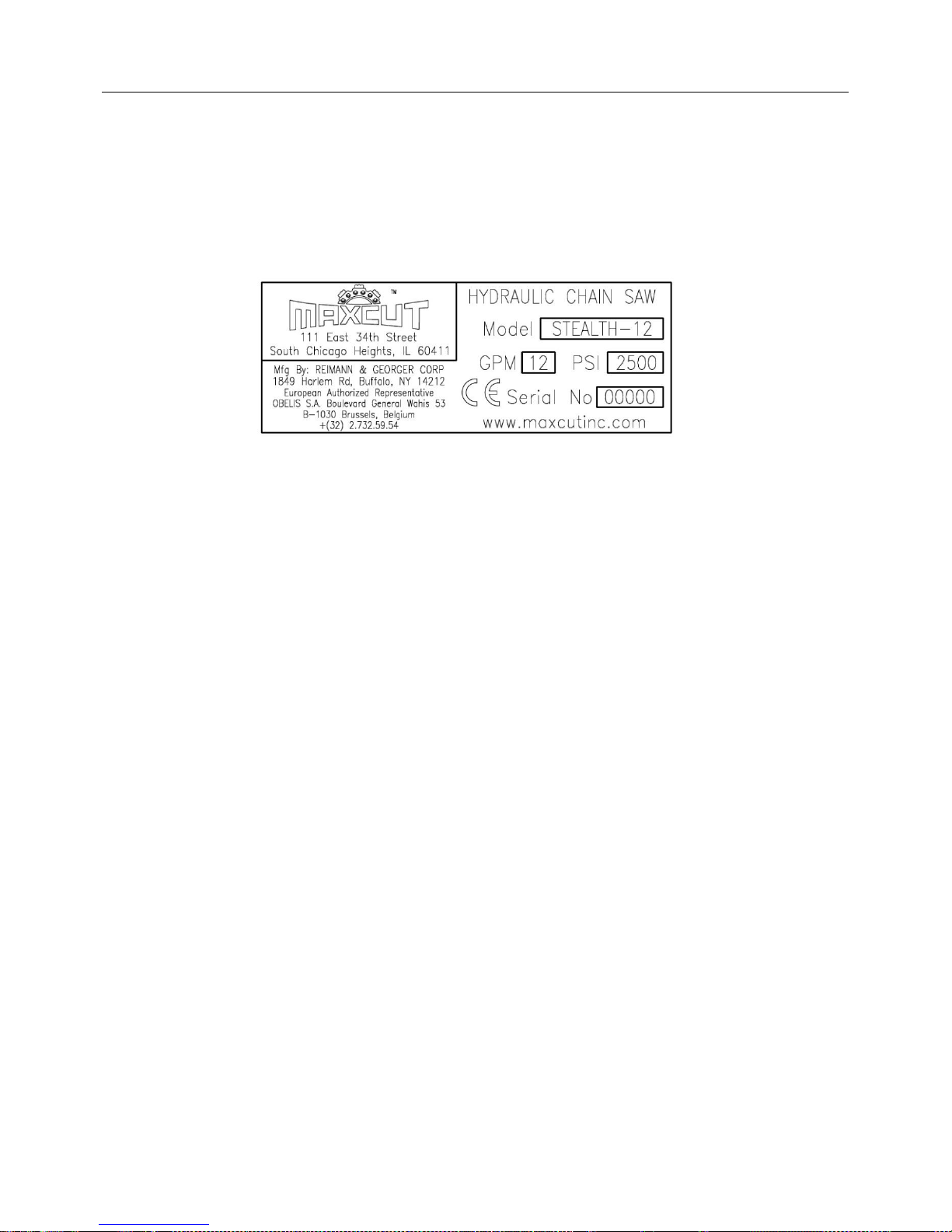
It is important to identify the saw completely and accurately whenever ordering spare
parts or requesting assistance in service. The saw has a product nameplate that states
the model and serial numbers. The saw label should appear as the sample nameplate
shown in Figure 1.
Record the model, serial number, and date of purchase on front page for future
reference.
FIGURE 1
Product Nameplate Sample
3. PRE-OPERATION INSPECTION AND SET-UP
The following systems must be checked before you can use the saw safely. Running the
saw with an undetected defect in any of these systems will quickly cause equipment
damage.
Hydraulic system
Water supply
Drive Sprocket
Guide Bar
Chain
3.1. CHECKING THE SYSTEM HYDRAULICS
3.1.1. Read and fully understand the operating manual for the hydraulic power
source being used.
3.1.2. Always check the hydraulic power supply flow and pressure output. Never
exceed the maximum hydraulic flow rate of 12 GPM (45LPM) or the
maximum pressure of 2500 psi (172 bar) that are stated on the product
nameplate/serial number tag. Overspeeding the chain causes increased
chain wear, leading to loss of strength and possible chain breakage.
3.1.3. If the oil flow from the hydraulic power supply cannot be adjusted below the
maximum flow rate, a flow divider must be installed. This will ensure the saw
receives the correct flow and excess oil is returned to the tank.
3.1.4. To protect the saw from excessive pressure, the pressure relief valve of the
hydraulic power source must be set at 2500 psi (172 bar). If this is not
possible, a separate pressure relief valve set at 2500 psi (172 bar) must be
installed in the system. If in doubt, contact your dealer.
3.1.5. The hydraulic power source must be fitted with a 10-25 micron oil filter.
3.1.6. Before making any hydraulic connections, inspect all hoses for leaks and
risks of rupture as follows:
MAXCUT INC. Page 7 of 31 MADE IN U.S.A.
Page 8
MAXCUT STEALTH-12 OPERATOR’S MANUAL
WARNING:
LIQUID UNDER HIGH PRESSURE CAN PIERCE THE SKIN, CAUSING
DEATH OR SERIOUS INJURY. IN CASE OF INJURY, GET IMMEDIATE
MEDICAL ATTENTION.
WARNING:
ENSURE HYDRAULIC HOSES ARE PROPERLY CONNECTED AND IN
GOOD CONDITION.
3.1.7. Inspect each hose for breaks, cracks, worn spots, bulges, chemical attack,
kinks or any other damage. Never try to stop any detected leak with any body
parts. DO NOT put your face close to suspected leaks. Hold a piece of
cardboard close to suspected leaks and then inspect the cardboard for signs
of hydraulic oil.
3.1.8. Replace a damaged hose immediately. Never repair the hose.
3.1.9. The saw uses flush-face quick-release couplings that are durable and easy to
clean. Wipe the mating surfaces of the couplings with clean rag prior to
making connection. They are always fitted such that the male part gives oil
and the female part receives oil.
3.2. CHECKING THE WATER SUPPLY
3.2.1. The water supply must be connected and tested before operating the saw.
Check for proper water distribution by triggering the saw with the hydraulic
power supply off and the chain not yet installed. You should see water
coming out the water ports each on the top and bottom of the bar and around
the nose sprocket. If not, use a small wire to clean the water ports, keeping in
mind that the water ports are tilted forward at 45 degrees.
3.2.2. The water pressure at the saw must be a minimum of 30 psi (2.1 bar) with a
minimum flow rate of 2.5 gpm (9.5 lpm). For best performance, use an in-line
water pump. Permanent chain, bar, and drive and nose sprocket damage will
occur if the saw is run without water, or with a water volume or pressure that
is too low. This damage can include excessive chain stretching, excessive
drive and nose sprocket wear, and shorter chain life.
MAXCUT INC. Page 8 of 31 MADE IN U.S.A.
Page 9
MAXCUT STEALTH-12 OPERATOR’S MANUAL
3.3. INSPECTION AND INSTALLATION OF THE DRIVE SPROCKET
3.3.1. Disconnect hydraulic hoses from the saw and place it on a flat surface.
3.3.2. Loosen the Cover Retaining Nuts (#28) using the Scrench (#79) and remove
the Cover (#26).
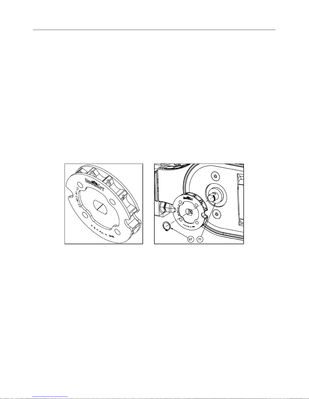
3.3.3. A new MaxCut Stealth-12 comes with the Drive Sprocket (DS-MC3-A1-12),
Felt Gasket for the motor shaft (#71), and Snap Ring (#67) already installed.
3.3.4. When installing a used drive sprocket, inspect it for wear marks on the teeth.
DO NOT use drive sprockets with wear marks deeper than 1/32‖
(approximately half way through the drive teeth) as shown in Figure 2.
A drive sprocket worn beyond this guideline increases the risk of damaging
the chain chassis.
3.3.5. Drive sprockets can be turn around to use the other side providing that the
wear marks do not exceed the recommended depth.
3.3.6. To install a drive sprocket remove the Snap Ring (#67), and lift the drive
sprocket from the motor shaft.
3.3.7. Install a new MaxCut Drive Sprocket (DS-MC3-A1-12) onto the motor shaft
and secure with the Snap Ring (#67) as shown in Figure 3.
3.3.8. Proceed to Section 3.4 for Installation of the Guide Bar.
FIGURE 2 FIGURE 3
Sprocket Wear Sprocket Installation
MAXCUT INC. Page 9 of 31 MADE IN U.S.A.
Page 10
MAXCUT STEALTH-12 OPERATOR’S MANUAL
Position Hole 1
3.4. INSPECTION AND INSTALLATION OF THE GUIDE BAR
3.4.1. Inspect the bar to ensure it is not bent or twisted.
3.4.2. As the bar rails wear down, sharp burrs are formed on the edge of the rails,
which are typically referred to as wire edges. If ignored, wire edges
mushroom over and affect cutting performance. Ensure that the bar rails are
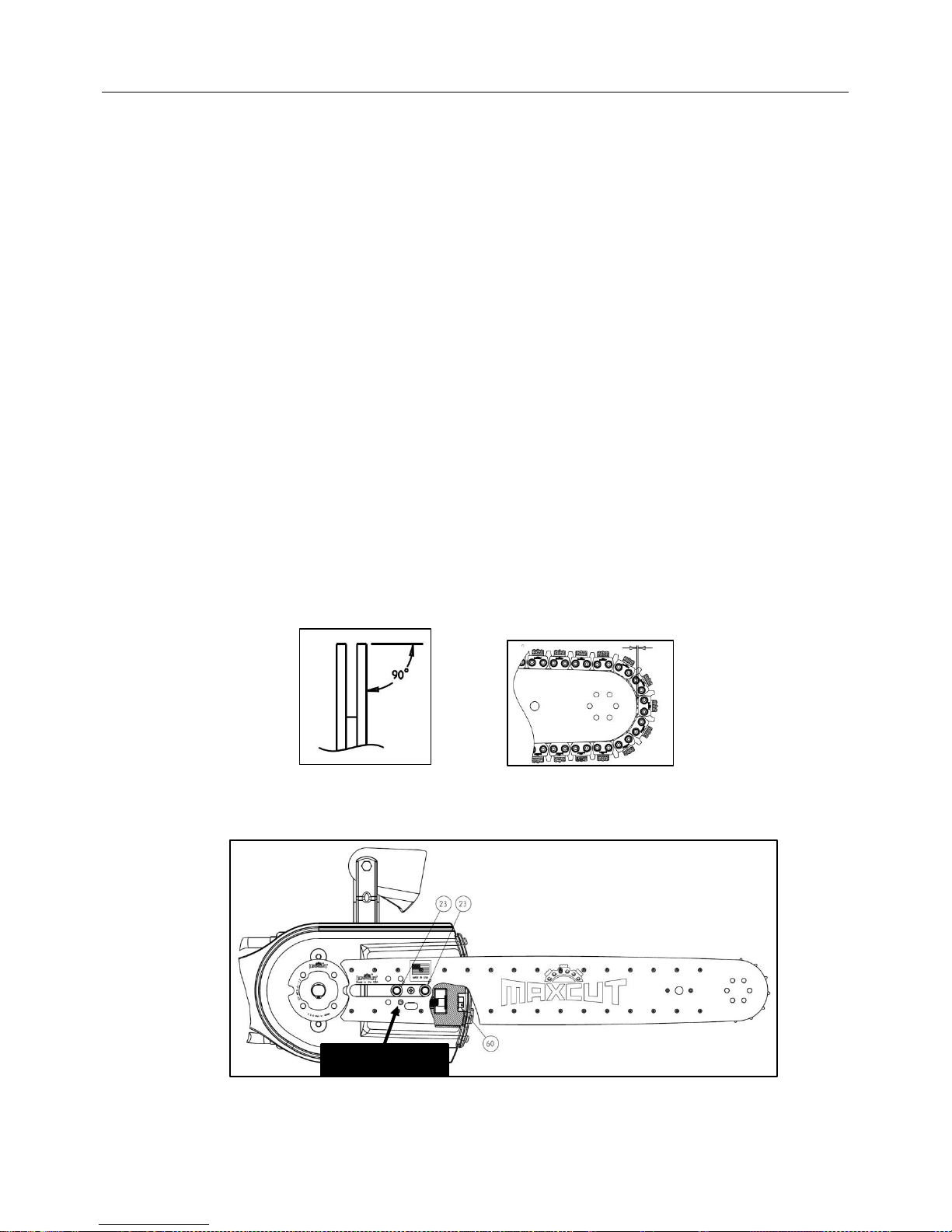
dressed squarely as shown in Figure 4 with the wire edges removed.
3.4.3. The bottom rail wears at a much faster rate than the top rail because of the
downward motion during cutting. It is recommended that the bar be turned
over on a regular basis to ensure even wear.
3.4.4. The bar rails are considered worn-out when the chain drive link contacts the
bottom of the groove in the bar. It is necessary to replace the bar at this time.
3.4.5. Ensure that the nose sprocket rotates freely.
3.4.6. Check the clearance between the nose of the bar side-plates and the chain
chassis. The bar must be replaced before the chain chassis begins to ride on
the nose of the bar side-plates as shown in Figure 5.
3.4.7. Refer to Figure 6 for the subsequent steps related to the installation of the
Guide Bar.
3.4.8. Prior to installing the bar, back out the bar adjustment Tensioner Screw (#60)
all the way by turning it counter-clockwise.
3.4.9. Install the bar by aligning the Adjustment Slot of the bar over the Bar Studs
(#23).
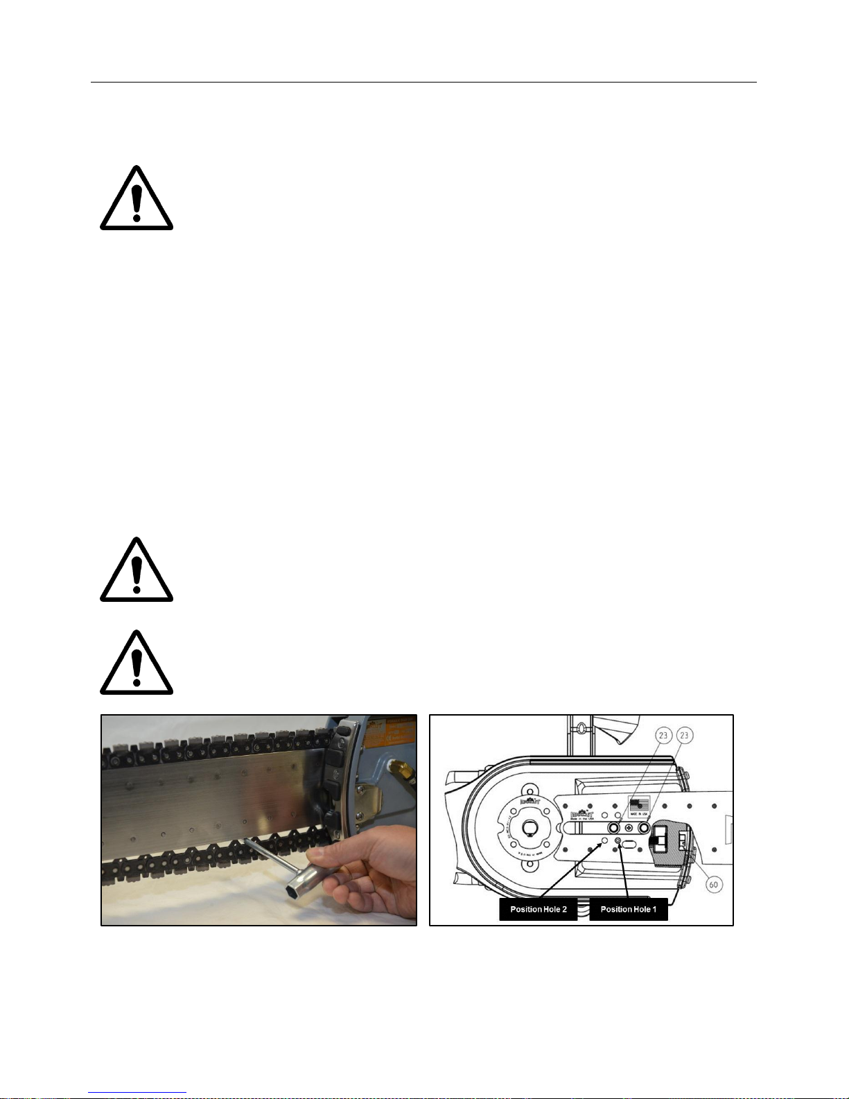
3.4.10. Align Position Hole 1 of the bar over the stud of the Tensioner Carriage (#53).
3.4.11. Proceed to Section 3.5 for the Installation of the Chain.
FIGURE 4 FIGURE 5
Dressed Guide Bar Nose Sprocket Clearance
FIGURE 6
Guide Bar Installation
MAXCUT INC. Page 10 of 31 MADE IN U.S.A.
Page 11
MAXCUT STEALTH-12 OPERATOR’S MANUAL
3.5. INSPECTION AND INSTALLATION OF THE CHAIN
3.5.1. Correct chain type selection is critical in maximizing chain life and cutting
performance. However, no direct rule determines which chain type is
optimum because many material factors also influence selection. Chapter 6
contains additional information on factors that affect chain life. Refer to
Figure 10 in that chapter for assistance in selecting the appropriate chain.
3.5.2. Inspect the chain for cracks, missing segments or bumpers, or signs of
overheating (discoloration) or other damage before mounting and before each
use.
3.5.3. Inspect the chain chassis for wear. Wearing of the chain chassis is typically
referred to as ―chain stretch.‖ If the bar adjustment screw cannot be tightened
sufficiently to prevent the drive links from coming completely out of the groove
move the Guide Bar forward so that Positon Hole 2 is engaged with the
Tensioner Carriage (#53). This will provide additional adjustment for the bar
and chain. If the chain still hangs below the guide bar more than ¼‖ replace
the chain.
3.5.4. Inspect the cutting segment for wear. The segment is considered worn out
when the segment height is worn to about 1/16‖, or when the segment and
chain chassis are the same width.
3.5.5. Directional chains MUST be installed in the proper direction according
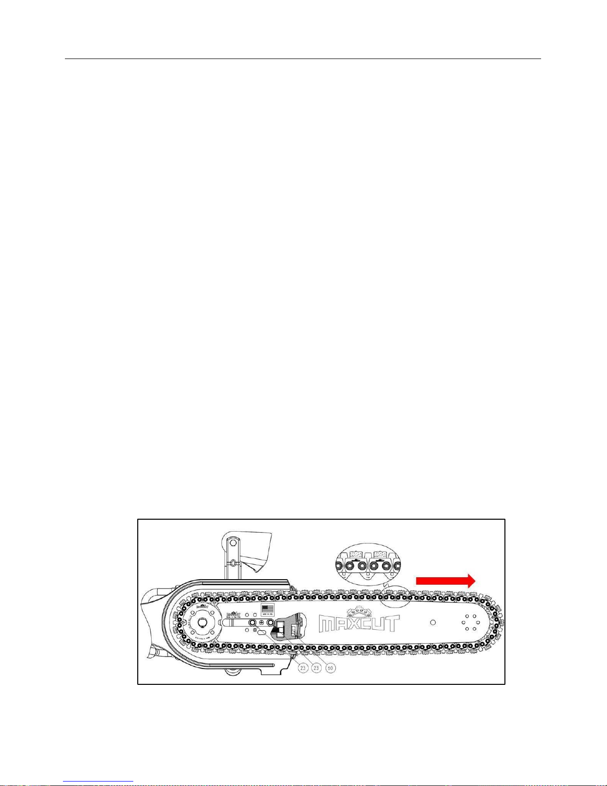
to the arrows stamped on the drive links as shown in Figure 7. Backward
(reverse) chain installation can cause excessive vibration, rough cutting,
reduced chain life, and damage to the chain. Non-directional chains can be
installed in either direction.
3.5.6. Install the chain by placing it around the drive sprocket. Then, run the drive
links into the top groove of the bar and wrap it around the nose sprocket.
3.5.7. Pre-tension the chain using the Scrench (#79) to tighten the Tensioner Screw
(#60). Make sure the all the drive links are positioned inside the groove of the
bar.
3.5.8. Replace Cover (#26) by aligning the slot on the left side with the Cover
Bracket (#69) on the saw.
3.5.9. Hand-tighten the Cover Retaining Nuts (#28) in an alternating fashion until
they are snug.
3.5.10. Proceed to Section 3.6 to adjust the tension of the chain.
FIGURE 7
Chain Installation
MAXCUT INC. Page 11 of 31 MADE IN U.S.A.
Page 12
MAXCUT STEALTH-12 OPERATOR’S MANUAL
WARNING:
FAILURE TO DISCONNECT THE POWER SUPPLY BEFORE STARTING
CAN CAUSE EQUIPMENT DAMAGE AND/OR PERSONAL INJURY.
CAUTION:
IF THE CHAIN IS TOO LOOSE DURING SAW OPERATION, THERE IS AN
INCREASED RISK OF CHAIN THROWING.
WARNING:
NEVER OPERATE THE SAW WITHOUT THE COVER INSTALLED. DOING
THIS CAN CAUSE PERSONAL INJURY.
3.6. TENSIONING THE CHAIN
Refer to the Figures 8 and 9 throughout the following procedure.
3.6.1. If you are not continuing from Section 3.5, disconnect hydraulic hoses from
the saw and place it on a flat surface.
3.6.2. Loosen the Cover Retaining Nuts (#28) using the Scrench (#79). The Cover
(#26) does not need to be removed.
3.6.3. Turn the bar adjustment Tensioner Screw (#60) clockwise until chain is
hanging approximately ¼‖ below the bottom of the bar. This can be easily
checked using the shaft of the Scrench (#79) to measure the clearance. The
shaft is ¼‖ so this is a quick way to confirm this.
3.6.4. Chain tension needs to be adjusted periodically before the drive links can
come completely out of the groove of the bar.
3.6.5. If the Tension Screw is all the way out and the chain hangs more than
¼”, move the Guide Bar forward so that Positon Hole 2 is engaged with
the Tensioner Carriage (#53). This will provide additional adjustment for
the bar and chain.
3.6.6. Use the Scrench (#79) to tighten the two Cover Retaining Nuts (#28).
FIGURE 8 FIGURE 9
Chain Tensioning Position Hole Location
MAXCUT INC. Page 12 of 31 MADE IN U.S.A.
Page 13
MAXCUT STEALTH-12 OPERATOR’S MANUAL
WARNING:
THE CHAIN GUARD MUST BE IN PLACE BEFORE STARTUP AND
DURING SAW OPERATION. FAILURE TO DO THIS CAN CAUSE SERIOUS
PERSONAL INJURY.
CAUTION:
NEVER RUN THE SAW WITH PLUGGED WATER PORTS. THIS CAN
CAUSE OVERHEATING AND RESULTING EQUIPMENT DAMAGE.
3.7. BREAKING IN A NEW CHAIN
3.7.1. Before using a new chain, the cutting segments should be dressed by cutting in
an abrasive material such as cinder blocks or bricks.
3.7.2. Looking at the cutting segment closely, you should be able to see the diamond
particles exposed and raised slightly higher than the surrounding surface.
3.7.3. Check the chain tension frequently during the first thirty minutes of operation of
a new chain and adjust as outlined in Section 3.6.
4. OPERATION
4.1. PLANNING THE CUT
4.1.1. This saw is not insulated. DO NOT start cutting without first de-energizing
electrical wiring imbedded in the concrete and near the cutting site.
4.1.2. When cutting a structural member such as a wall, ensure the cut will not
weaken the structure such that it will cause a failure.
4.1.3. Plan the sequence of cuts to prevent the weight of the material being cut from
pinching the bar and chain, causing it to bind. Start with the base horizontal
cut and proceed with the remaining cuts.
4.1.4. The material being cut must be rigidly supported to prevent it from falling and
causing personnel injury.
4.1.5. The planned line of cut can be outlined with a permanent marker for a visual
guide.
4.1.6. For long vertical or horizontal cuts, the cutting line can be first scored with a
groove using the nose of the bar. The groove will help guide the bar for a
straight cut.
4.2. CUTTING PROCEDURE
4.2.1. Review all safety procedures in Chapter 1 of this manual and in the manual
supplied with your hydraulic power unit.
4.2.2. Before connecting the hydraulic lines, connect water supply to the saw.
Check the water ports for proper water distribution by triggering the saw.
Water should be coming out of the water ports each on the top and bottom of
the bar and around the nose sprocket. If not, remove chain and use a small
wire to clean the water ports. Note that water ports are tilted forward at a 45°
angle.
MAXCUT INC. Page 13 of 31 MADE IN U.S.A.
Page 14

MAXCUT STEALTH-12 OPERATOR’S MANUAL
WARNING:
NEVER DISCONNECT ANY HYDRAULICALLY OPERATED PART OF THE
SAW OR REMOVE HYDRAULIC COMPONENTS, LINES, OR FITTINGS
WHILE THE POWER SOURCE IS RUNNING OR WHENEVER THE
HYDRAULIC FLUID IS HOT.
4.2.3. Connect hydraulic lines to the saw.
4.2.4. Grasp the front handle with your left hand. Use the appropriate part of the
handle for making the first cut.
4.2.5. Grasp rear handle with your right hand.
4.2.6. Disengage the Safety Release (#2) then depress (squeeze) the Throttle
Trigger lever (#3) to start the saw.
4.2.7. Always operate a new chain at the rated rpm for two minutes before cutting to
verify proper chain mounting and tension. The chain should be moving away
from you (i.e. forward direction) at the top of the power bar. If it is not, change
the position of the forward/reverse lever on the power unit, if equipped, or
reverse hydraulic connections at power unit.
4.2.8. Position the saw in the appropriate place to make the desired cut.
4.2.9. When putting the chain into an existing cut, the cut must be the same width
as the chain. Putting the chain into an existing cut narrower than the chain will
rapidly wear the side clearance of the chain and could cause chain breakage.
4.2.10. When starting a cut, DO NOT bang the chain into the cutting medium. Jarring
impacts can decrease the life and performance of the chain and bar.
4.2.11. Plan the cutting strategy before starting. Once the saw starts cutting, you
cannot change direction of a cut easily. DO NOT twist the bar in the cut.
4.2.12. DO NOT apply excessive feed force. A constant chain speed is important for
optimum cutting.
4.2.13. When plunge cutting, increase the opening of the cut by rocking the saw up
and down. Aggressive plunge forces may cause the saw to jam when exiting
the cut. If the saw does become jammed in a plunge cut, you can release the
saw as described in Chapter 7.
4.2.14. Check chain tension frequently during cutting.
4.3. SHUTTING DOWN AND STORING THE SAW
4.3.1. Stop the saw by releasing the Throttle Trigger lever (#3).
4.3.2. Stop the hydraulic power source following the procedure in the respective
instruction manual.
4.3.3. Clean the slurry off the saw with water before it dries.
4.3.4. Shut off water supply.
4.3.5. Disconnect the hydraulic hoses from the saw.
4.3.6. Allow the water to drain out of the saw by pointing the nose down and
triggering the valve on. If available, blow the water out of the saw with
compressed air. Spray entire saw with a light coating of oil to make
cleanup easier next time. Make sure the chain, bar, and bar nose
sprocket have a coating of oil to prevent rusting.
4.3.7. Secure the saw and hydraulic power source to prevent unauthorized use.
MAXCUT INC. Page 14 of 31 MADE IN U.S.A.
Page 15
MAXCUT STEALTH-12 OPERATOR’S MANUAL
CAUTION:
BEFORE STARTING ANY MAINTENANCE, DISCONNECT SAW FROM
HYDRAULIC POWERSOURCE TO PREVENT ACCIDENTAL STARTUP.
WARNING:
DURING ANY MAINTENANCE OR REPAIR PROCEDURES, DO NOT
ATTEMPT ANY SAWING. THIS CAN CAUSE EQUIPMENT DAMAGE
AND/OR PERSONAL INJURY.
4.3.8. Store the saw away from excessive heat or moisture. Store in a clean, dry
area away from exposure to high humidity, water, other liquids, or freezing
temperatures. Avoid temperatures low enough to cause condensation on the
chain when moving it from storage to a higher temperature. Always handle
and store chains carefully.
4.3.9. DO NOT stack material on top of the saw that may cause the chain or bar to
bend or deform.
5. MAINTENANCE
5.1. GENERAL MAINTENANCE RULES
5.1.1. Hydraulic fluid can become contaminated after extended periods of use which
can cause restrictions in the system. Check to see that the fluid is clean, and
change at recommended intervals to extend saw’s life. Refer to the respective
manual for maintenance information on the hydraulic power source.
5.1.2. Proper maintenance of the saw and related equipment requires timely
adhering to all the guidelines given in this chapter. Proper maintenance is
required to maintain the system in good condition and free of defects.
5.1.3. Review and follow all the safety rules given in Chapter 1 before attempting
any maintenance.
5.1.4. Only authorized personnel should be allowed in the maintenance area.
Authorized personnel are the trained people as defined below and their
supervision.
5.1.5. Repairs must be made only by trained personnel. A trained person is one
who has read and thoroughly understands this instruction manual and related
equipment manuals and, through training and experience, has shown
knowledge regarding the safe operational procedures.
5.2. GUIDE BAR MAINTENANCE
5.2.1. Ensure the bar and nose sprocket has a light coat of oil to prevent rusting.
5.3. CHAIN MAINTENANCE
5.3.1. Inspect the chain before mounting and before each use.
5.3.2. Ensure there are no missing segments or bumpers.
5.3.3. Ensure there are no signs of cracking, overheating, or other damage.
5.3.4. Check the wear of the chain chassis, typically referred to as ―chain stretch‖,
by tensioning the chain as described in Section 3.6. The chain chassis is
MAXCUT INC. Page 15 of 31 MADE IN U.S.A.
Page 16
MAXCUT STEALTH-12 OPERATOR’S MANUAL
considered worn out or excessively ―stretched‖ if the chain cannot be
tensioned sufficiently to prevent the drive links from coming completely out of
the groove. Discard the chain.
5.3.5. Check the segment wear. The segment is considered worn-out when the
height is worn down to about 1/16‖, or when the segment width is the same
as the chain chassis.
5.3.6. After each use clean the slurry and debris off the chain; then apply a light
coating of oil to prevent rusting.
5.4. POWERHEAD MAINTENANCE
5.4.1. After using saw inspect all hardware and tighten fasteners as needed.
5.4.2. Inspect the Felt Washer (#71) to ensure it is integral, replace if damaged.
5.4.3. Maintain the Tensioner Assembly by removing the Guide Bar Wear Plate
(#24). Clean the slot, Tensioner Carriage (#53), and Tensioner Screw (#60).
Apply new grease to the entire assembly and replace the Wear Plate (#24) as
shown in Section 8.1.
5.4.4. Remove Spool Cover (#12) and lubricate Spool Linkage (#9) and associated
pivot points.
5.4.5. Inspect, clean, and lubricate Bar Studs (#23).
5.4.6. Inspect Bumper Pad (#58) and replace when it becomes worn.
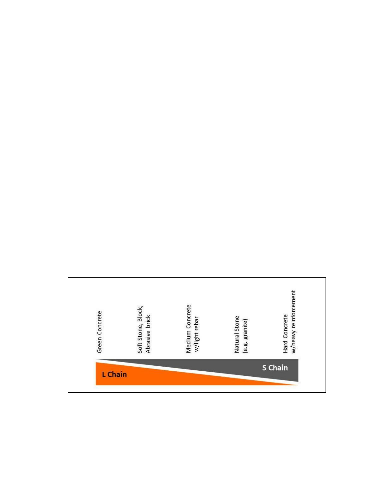
6. FACTORS AFFECTING CHAIN LIFE
Optimum performance from your chain saw will depend largely on selecting the proper
chain for the application. If the cutting medium is too soft for the chain rating used, you
may get fast chain wear. If the cutting medium is too hard for the chain rating used, you
will get segment glazing and/or very poor cutting performance. This chapter is a guide in
making the proper chain selection.
FIGURE 10
Chain Selection Guide
6.1. HOW DIAMOND SEGMENTS WORK
Cutting concrete, stone, and other hard, brittle materials is a grinding or abrading action.
Cutting segments are composed of hard, abrasion resistant diamond particles
distributed randomly in a metal matrix. The diamonds abrade or scratch out particles of
MAXCUT INC. Page 16 of 31 MADE IN U.S.A.
Page 17

MAXCUT STEALTH-12 OPERATOR’S MANUAL
STANDARD
SCALE
HARDNESS CRITERIA
DIAMOND
CORUNDUM
TOPAZ
10
9
8
Very hard aggregates (flint, chert, some basalt, some
quartz, some trap rock)
QUARTZ
FELDSPAR
APATITE
7
6
5
Hard aggregates (some quartz, some granite, some
basalt, some river gravel, some trap rock)
Medium hard aggregates (some granite, some river rock)
FLUORITE
CALCITE
GYPSUM
TALC
4
3
2
1
Medium aggregates (dense limestone, sandstone,
dolomite, marble)
Medium soft aggregates (soft limestone)
the hard substrates during the cutting operation. Even though diamond is the hardest
substance known to man, it does wear out or break down. New diamonds are exposed
as the metal bond wears away. Abrasive particles will wear down a metal bond faster
than hard, brittle particles.
6.2. MATERIAL FACTORS AFFECTING CHAIN LIFE
There are several material factors that affect the performance and life of diamond
segmented chain. Six major factors are summarized as follows:
6.2.1. Aggregate Hardness – There are many different types of rocks used as
concrete aggregate. Some aggregates are very hard like flint and some are
very soft like limestone. A general rule is that the harder the aggregate, the
softer the segment bond that is needed. Another general rule is that the
harder the aggregate, the slower the chain will cut. A common way of
measuring aggregate hardness is the Moh’s Scratch Test.
MOH’S SCALE
HARDNESS CRITERIA
6.2.2. Aggregate Size - As the rock size increases, cutting generally will be slower
and the chain life will decrease. Common U.S. aggregate sizes are sieved at
1-1/2‖, 1‖, 3/4‖, and 3/8‖.
6.2.3. Size and Quantity of Reinforcing - Steel reinforcing critically affects diamond
chain life. Quantifying the amount of reinforcing can generally be divided into
two levels:
Heavy
• 5/8‖ (16 mm) diameter or larger with any center distance
• 1/2‖ (13 mm) diameter or larger with less than 4‖ (100 mm) center distance
• Pre-stressed cable/wire
Light
• 1/2‖ (13 mm) diameter with greater than 4‖ (100 mm) center distance
• 3/8‖ (10 mm), 1/4‖ (6 mm) or smaller diameter with any center distance
• Wire mesh
Steel reinforcing creates large impact forces on both the diamonds and the chain chassis,
reducing both the segment life and chain life. Generally, as the ratio of steel in the concrete
cross section increases, the performance and chain life are greatly reduced. When steel is
encountered while cutting, the feed force should be reduced.
MAXCUT INC. Page 17 of 31 MADE IN U.S.A.
Page 18

MAXCUT STEALTH-12 OPERATOR’S MANUAL
CONCRETE HARDNESS
CONCRETE STRENGTH (PSI)
TYPICAL APPLICATIONS
Very Hard
8000 or more
Nuclear Plants
Hard
6000-8000
Bridges, Piers
Medium
4000-6000
Roads
Soft
3000
Sidewalks, Patios
6.2.4. Sand Shape - Angular types of sand such as manufactured (crushed) and
bank sand are more abrasive than rounded sand such as river or wind-blown
sand. Angular sands decrease both the segment life and chain life. The
diamond segment bond is abraded at a higher rate. Sharp, fine sand
increases the wear on the chain chassis, especially if the sand penetrates the
rivet joints. Proper water flow rate is critical in maximizing chain life in
abrasive conditions. Generally, a harder segment bond is desired for
abrasive conditions.
6.2.5. Compressive Strength of Concrete - Strength of concrete is a combination of
many factors and is usually measured in pounds per square inch (psi). Even
though the compressive strength does not indicate the aggregate hardness,
there is a relationship between the compressive strength and the hardness of
the concrete. A general rule is that the higher the compressive strength, the
harder the concrete. Generally, higher strength concretes decrease expected
chain life.
COMPRESSIVE STRENGTH
6.2.6. Green or Cured Concrete - A very important material factor is the cure time of
the concrete. Green concrete is fresh poured, typically less than 24 hours. It
is more abrasive because the sand is not fully bonded with the cement and
coarse aggregate. Chain life is decreased in both the chassis joints and
diamond segments. A harder segment bond is desired for abrasive
conditions.
6.3. OPERATIONAL FACTORS AFFECTING CHAIN LIFE
There are eight operational factors affecting chain life which are summarized as follows:
6.3.1. Water Flow Rate - The water flow rate to the chain is a critical factor in
both the segment life and chain life. Water is the system coolant and
flushing agent for grit and particulate. It is important to note that the required
water flow is the flow to the chain and not the flow from the hose or water
supply. Water leaks or plugged water orifices may actually decrease the flow
to the chain. The minimum water flow to the chain is 2.5 gpm from the guide
bar at a minimum pressure of 30 psi. It is recommended to use higher water
pressure if possible for abrasive conditions.
Insufficient water supply decreases chain life two (2) ways:
Chassis wear or ―stretch‖ is increased, resulting in wearing out of the
chassis rivets and/or drive link holes.
Segment bond wear is increased due to the abrasive slurry not being
flushed out.
MAXCUT INC. Page 18 of 31 MADE IN U.S.A.
Page 19

MAXCUT STEALTH-12 OPERATOR’S MANUAL
6.3.2. Mode of Cutting
Plunge vs. Slab - Plunge cutting increases diamond segment wear
because both impact and loading increase. Depending on the ratio of
plunges and the cutting depth, chain life can be reduced.
Buried nose vs. Through cut - When cutting with the bar nose buried in
the cut, the slurry increases the wear on both the chain and segment.
It can be expected that both the segment life and chain life will be
decreased.
6.3.3. Direction of Cutting (Horizontal vs. Vertical) - Cutting horizontally decreases
chain life. When cutting vertically (up or down), feed load is applied mainly to
the top diamond surface. Cutting horizontally applies downward load to the
diamond top and gravitational load to the diamond side from the tool weight.
This side load creates non-uniform side wear on the segment and can
eventually cause side clearance loss.
6.3.4. Cutting Technique (Impact vs. Smooth) - Impacting the cutting surface with
the chain decreases the chain life. Impact forces create excessive stress and
wear in the chain components. Impact forces also dull the diamond
segments, decreasing the segment life and performance.
6.3.5. Rotational Speed - Optimum cutting performance is achieved when operating
with a hydraulic input of 12 GPM (6500 RPM). Operating with a hydraulic
input excess of 12 GPM will decrease the life of both the segment and chain.
6.3.6. Excessive Feed Force - Excessive feed force dulls the diamond segments,
decreasing the segment life and performance.
6.3.7. Chain Tension - Improper chain tension increases chassis wear in the rivets
and/or drive link holes, possibly ―stretching‖ the chain beyond its usable pitch
diameter.
6.3.8. Improperly Maintained Bar and/or Drive Sprocket - Improperly maintained bar
rails, nose sprocket, and/or drive sprocket can increase the chain chassis
wear, causing premature ―stretching‖ and possibly uneven segment wear.
6.4. CHAIN END-OF-LIFE MODES
There are three different end-of-life conditions that can occur, depending on a specific
combination of factors as discussed in Sections 6.2 and 6.3. These conditions are as
follows:
6.4.1. Wear Out of Diamond Top Surface - This condition occurs when the diamond
segment height is worn down to about 1/16‖ (0.0625‖ or 1.5 mm) remaining.
6.4.2. Loss of Diamond Side Clearance - This condition occurs when the diamond
side surfaces are worn at a rate higher than the diamond top surfaces. The
resulting end-of-life condition is a diamond segment width of about 0.187‖
(4.7 mm).
6.4.3. Wear Out of Chain Chassis - This condition is characterized by worn chain
rivets and chain drive link holes, and appears as ―stretch.‖ This mode leaves
a portion of the diamond segment unused. Excessive ―stretch‖ is evident
when the drive links can come completely out of the groove after tensioning
the chain mounted on the bar.
MAXCUT INC. Page 19 of 31 MADE IN U.S.A.
Page 20

MAXCUT STEALTH-12 OPERATOR’S MANUAL
SYMPTOM
CAUSE
CORRECTIVE ACTION
Saw will not cut
straight.
Operator feed force not
applied directly over
centerline of bar.
Frame is bent.
Uneven bar rail wear.
Uneven chain segment
profile.
Operator unable to
maintain a level and
straight saw position.
Bent or twisted bar.
Move hand closer to centerline of bar.
Repair or replace frame.
Dress rails square or turn bar over as
described in Section 3.4.
Replace bar.
Redress segment by cutting in an abrasive
medium such as concrete, cinder blocks, or
bricks.
Use an attached guide on wall (i.e., 2 x 4,
wood rails).
Use a precut slot in the wall the full length
of desired cut to be made.
Replace bar.
Premature chain
stretch.
Chain is mounted
backwards with
bumper side of
diamond segment not
being the side to first
contact the cutting
groove.
Insufficient water
supply.
Hydraulic flow is
exceeding rated saw
gpm (lpm).
Inspect chain as described in Section 3.5
before re-installing.
Plugged bar water ports:
(a) Clean ports with #10 wire.
(b) Check and verify that water supply is
clean.
(c) Install inline water filter.
(d) If unable to maintain a minimum water
pressure of 30 psi (3.5 bar) with a minimum
flow rate of 2.5 gpm (9.5 lpm), use an inline
water pump.
Adjust power supply or use a flow divider to
limit hydraulic flow to rated saw gpm (lpm).
7. TROUBLESHOOTING
The following chart is intended to assist with troubleshooting the MaxCut Stealth-12.
While not all inclusive, the chart outlines the most common causes of a problem and the
recommended course of action. Consult your hydraulic power supply manual for
troubleshooting that part of your system.
MAXCUT INC. Page 20 of 31 MADE IN U.S.A.
Page 21

MAXCUT STEALTH-12 OPERATOR’S MANUAL
Loose chain tension.
Excessive groove worn
in drive sprocket.
Improper operator
technique.
Maintain the chain tension as described in
Section 3.6.
Replace drive sprocket.
Minimize impacting when cutting steel.
Minimize rapid chain stops, such as
jamming.
Excessive vibration
and rough cutting.
Loose chain tension.
Loose Cover Retaining
Nuts.
Chain installed
backwards on saw as
described above under
the heading
―Premature Chain
Stretch.‖
Worn bar nose
sprocket.
Worn drive sprocket.
Excess feed force
when cutting rebar.
Maintain chain tension as described in
Section 3.6.
Tighten bolts as described in Section 3.6.
Inspect chain as described in Section 3.5
before re-installing.
Replace guide bar.
Replace drive sprocket.
Reduce feed force.
Bar nose sprocket
does not turn
Nose bearings worn
and are jammed
between inner and
outer race.
Bent or twisted bar.
Replace guide bar.
Replace guide bar.
Saw cuts slowly
Loss of diamond
segment side or top
clearance.
Chain segment dulled
because of continuous
use in hard material or
steel.
Wire edged bar rails.
Replace chain.
Redress segment by cutting in abrasive
material such as concrete building block or
brick.
Choose the right chain for the cutting
condition as outlined in Section 6.
Dress the top and sides of the bar rails
squarely with a grinder or belt sander. See
Section 3.4.
MAXCUT INC. Page 21 of 31 MADE IN U.S.A.
Page 22

MAXCUT STEALTH-12 OPERATOR’S MANUAL
Hydraulic flow is below
saw rated GPM flow.
Hydraulic pressure
relief is set below 2500
psi.
Drive sprocket slipping
on drive shaft.
Chain tension too tight
or too loose.
Chain slipping through
worn teeth on drive
sprocket.
Hydraulic hoses too
long or too small in
diameter.
Hydraulic oil leaking on
chain.
Adjust hydraulic power source to 12 gpm.
Adjust hydraulic power source.
Replace drive sprocket.
Adjust chain tension as outlined in Section
3.6.
Install new drive sprocket. See Section 3.3.
Select the shortest hose that is feasible.
The maximum hose length for 1/2‖ hose is
100 feet.
Check the following locations for leaks:
(a) Quick disconnect fittings.
(b) Saw control valve assembly.
(c) Saw motor hydraulic fittings.
(d) Saw motor shaft.
(e) O-ring leak at valve spool assembly
which controls both oil and water flow—
replace O-ring.
Adjust or replace appropriate part.
Saw wedged tightly in
plunge cut.
Excessive feed force
when exiting back side
of plunge cut.
Turn off power supply; then loosen chain
tension and remove saw from cut.
Saw is binding in the
cut.
Bar is bent or twisted.
Frame is bent.
Saw not cutting a
straight line.
Side clearance of chain
worn.
Wire edged bar rails.
Replace bar.
Repair or replace frame.
Refer to ―Saw Will Not Cut Straight‖ part of
troubleshooting chapter.
Replace chain.
Dress top and sides of the bar rails
squarely with a grinder or belt sander. See
Section 3.4.
MAXCUT INC. Page 22 of 31 MADE IN U.S.A.
Page 23
MAXCUT STEALTH-12 OPERATOR’S MANUAL
DESCRIPTION
SECTION
PAGE
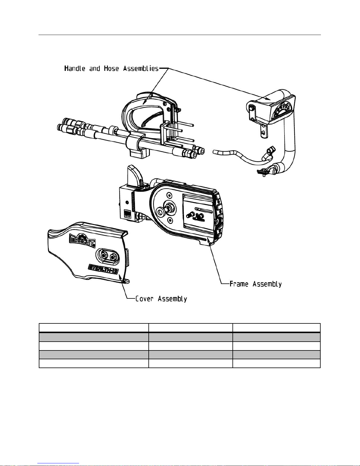
Frame Assembly
8.1
24-25
Cover Assembly
8.2
26
Handle and Hose Assemblies
8.3
27-28
Scrench Tool
8.4
29
8. PARTS LISTS
MAXCUT INC. Page 23 of 31 MADE IN U.S.A.
Page 24
MAXCUT STEALTH-12 OPERATOR’S MANUAL
ITEM
NUMBER
PART
NUMBER
QUANTITY
DESCRIPTION
13
90060
1
Screw - 8-32 x 3/8"
23
20010
2
Bar Stud
24
10080
1
Wear Plate - Guide Bar
46
90130
2
Screw - 3/8-16 FHCS x 1.25"
53
20030
1
Tensioner Carriage
60
20040
1
Tensioner Screw
63
90170
2
Tensioner Washer - 0.390" ID x 0.625" OD
64
90180
1
Tensioner E-Clip
67
90190
1
Snap Ring - To Retain Sprocket (5/8" Shaft Size)
68
70040
1
Personal Protection Equipment (PPE) Label
70
90200
1
X-Profile O-ring - 3/16" Cord Stock (~21.5" Length)
71
30200
1
Felt Washer (5/8" ID)
82
70010
1
―Made in USA‖ Label
83
10170
1
Support Washer
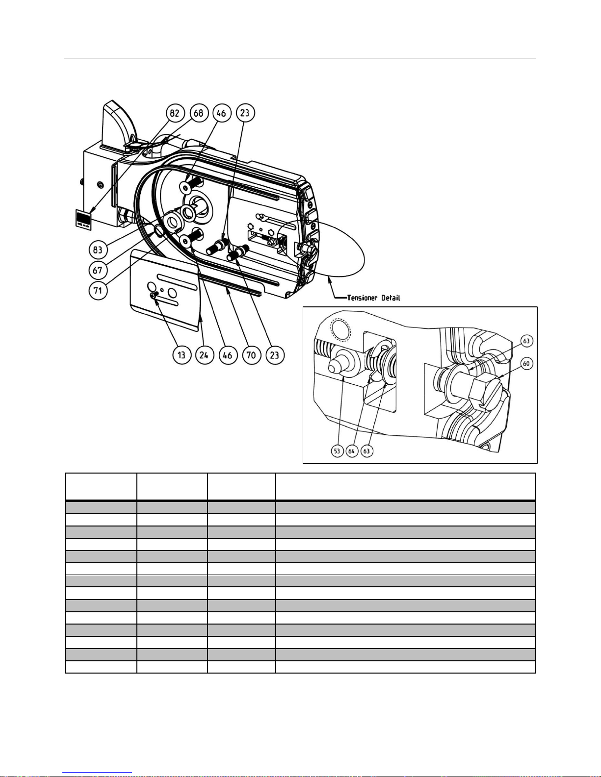
8.1. PARTS LIST - FRAME ASSEMBLY
MAXCUT INC. Page 24 of 31 MADE IN U.S.A.
Page 25
MAXCUT STEALTH-12 OPERATOR’S MANUAL
ITEM
NUMBER
PART
NUMBER
QUANTITY
DESCRIPTION
8
30030
1
3-Port Hydraulic Valve
9
10040
1
Spool Linkage
10
90040
1
Roll Pin - 5/32" x 1/2" Long - Upper
11
90050
1
Roll Pin - 5/32" x 5/8" Long - Lower
12
40010
1
Spool Cover
13
90060
1
Screw - 8-32 x 3/8"
18
30070
1
Water Hose Fitting - 1/4" barb x 1/8" NPT, straight
22
80040
1
Saw Frame
39
30010
1
Hydraulic Flared Tube - Supply, Valve to Motor
40
30020
1
Hydraulic Flared Tube - Return, Motor to Valve
43
30140
3
Fitting - Hydraulic, Male JIC-8 to Male SAE-8 O-ring, 90°
44
30150
1
Fitting - Hydraulic, Male JIC-8 to Male SAE-8 O-ring, 45°
45
30160
1
Motor
47
90140
2
Washer - 3/8" ID
48
90150
2
Nut - 3/8-16 Nylon Lock
58
50010
1
Bumper – Rubber
62
N/A
1
Serial Number Tag
69
10100
1
Cover Bracket
72
10140
3
Bumper Screw
73
10110
1
Bumper Frame
75
30180
1
Water Hose Fitting - 3/8" barb x 1/8" NPT, straight
77
10120
1
Scrench Clip
80
90220
2
8-32 x 3/8 Philips Truss Machine Screw (Stainless Steel)
Interchangeable with Item #13
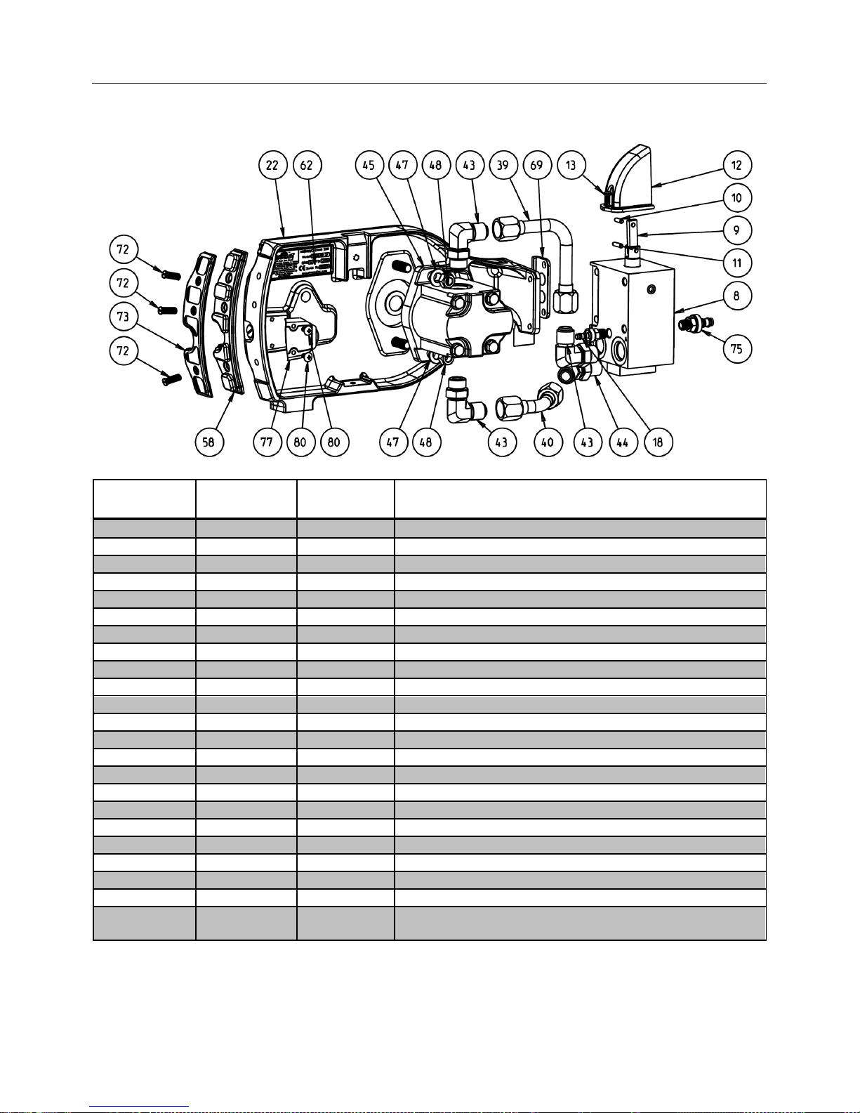
PARTS LIST - FRAME ASSEMBLY (Continued)
MAXCUT INC. Page 25 of 31 MADE IN U.S.A.
Page 26
MAXCUT STEALTH-12 OPERATOR’S MANUAL
ITEM
NUMBER
PART
NUMBER
QUANTITY
DESCRIPTION
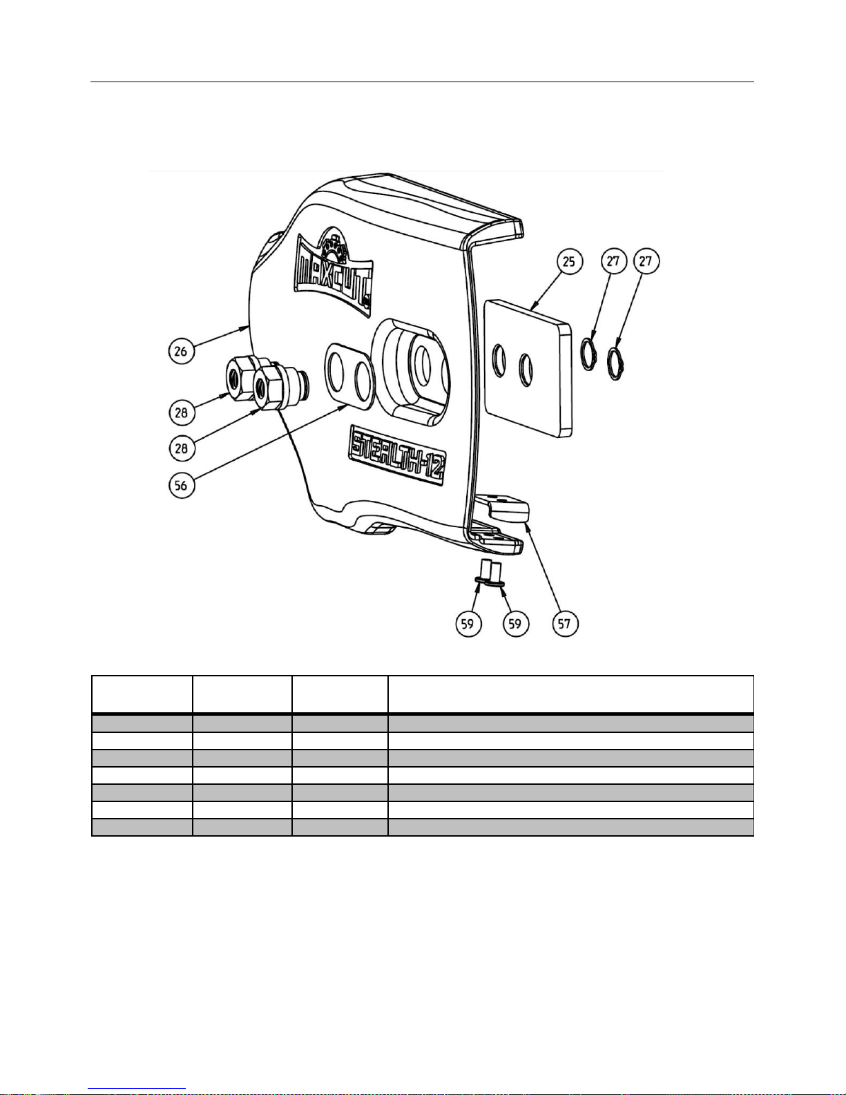
25
10020
1
Clamping Plate - Guide Bar
26
80050
1
Cover
27
90070
2
Snap Ring - Cover Retaining Nut, 9/16" Shaft Size
28
20020
2
Cover Retaining Nut
56
10070
1
Washer Plate
57
10050
1
Strike Plate
59
90160
2
Rivet (strike plate) 3/16" x 3/8"L
8.2. PARTS LIST – COVER ASSEMBLY
MAXCUT INC. Page 26 of 31 MADE IN U.S.A.
Page 27
MAXCUT STEALTH-12 OPERATOR’S MANUAL
ITEM
NUMBER
PART
NUMBER
QUANTITY
DESCRIPTION
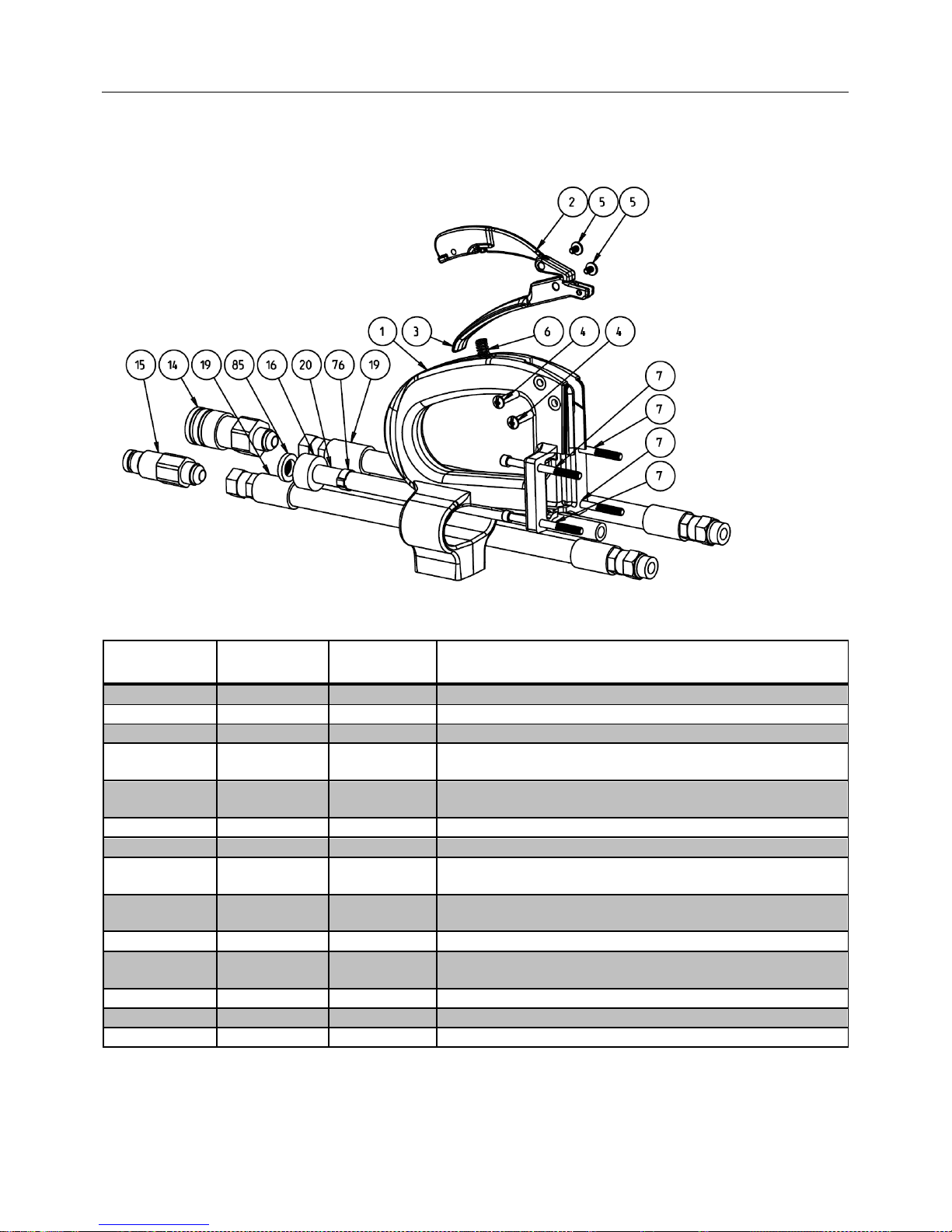
1
80010
1
Rear Handle
2
80020
1
Safety Release
3
80030
1
Throttle Trigger
4
90010
(4&5 together)
2
Barrel Nut
(1/4" OD x 1", 10-24 THD)
5
90010
(4&5 together)
2
Screw - For Barrel Nut
(10-24 THD, Included with Barrel Nut)
6
90020
1
Spring (Safety Release)
7
90030
4
Screw - 1/4-20 x 3" SHCS
14
30040
1
Quick Disconnect Fitting – Supply
(Female 3/8" body x Male JIC-8)
15
30050
1
Quick Disconnect Fitting - Return
(Male 3/8" body x Male JIC-8)
16
30060
1
Water Inlet Fitting (GHT x 3/8" hose barb)
19
30080
2
Hydraulic Hose - Supply and Return
(Starflex 3000 -08 x 12")w/ 1/2" JIC Swivel)
20
30090
1
Hose - Water Inlet (3/8" ID x 13")
76
30190
1
Hose Clamp (11/16" ID for 3/8" hose)
85
30230
1
Inlet Water Hose Screen
8.3. PARTS LIST – HANDLE AND HOSE ASSEMBLIES
MAXCUT INC. Page 27 of 31 MADE IN U.S.A.
Page 28
MAXCUT STEALTH-12 OPERATOR’S MANUAL
ITEM
NUMBER
PART
NUMBER
QUANTITY
DESCRIPTION
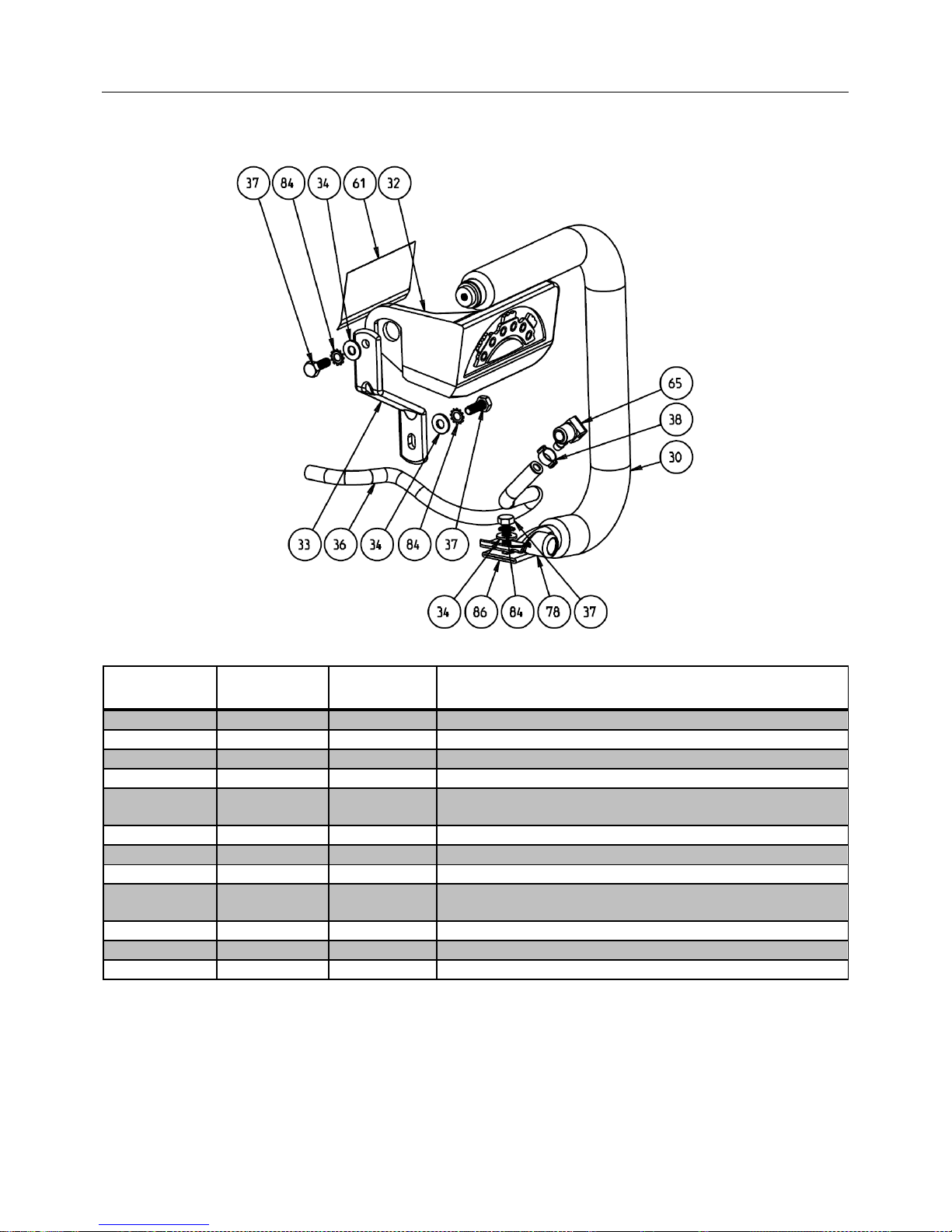
30
90080
1
Foam - For Tube Handle
32
40020
1
Hand Guard
33
10060
1
Bracket - Handle to Saw Frame
34
90090
3
Washer - 1/4" ID
36
30110
1
Hose - Water from Valve to Saw Body
(1/4" ID x 10.5")
37
90110
3
Screw - 1/4-20 x 3/4" Lg
38
90120
1
Hose Clamp (7/16" ID for 1/4" hose)
61
70020
1
Warning Label
65
30170
1
Water Hose Fitting - Saw Body In
(1/4" barb x 1/4" NPT, 90°)
78
10130
1
Scrench Hub
84
90240
3
Star Washer - ¼‖ ID
86
10180
1
Tube Handle Assy
PARTS LIST – HANDLE AND HOSE ASSEMBLIES (Continued)
MAXCUT INC. Page 28 of 31 MADE IN U.S.A.
Page 29
MAXCUT STEALTH-12 OPERATOR’S MANUAL
ITEM
NUMBER
PART
NUMBER
QUANTITY
DESCRIPTION
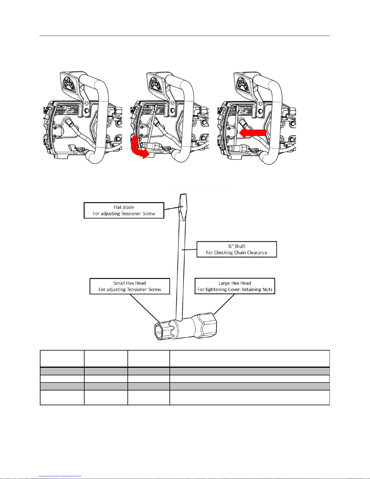
77
10120
1
Scrench Clip
78
10130
1
Scrench Hub
79
10160
1
Scrench
80
90220
2
8-32 x 3/8 Philips Truss Machine Screw (Stainless Steel)
Interchangeable with Item #13
8.4. PARTS LIST – SCRENCH TOOL
Stowing the Scrench Tool – Step by Step
MAXCUT INC. Page 29 of 31 MADE IN U.S.A.
Page 30

MAXCUT STEALTH-12 OPERATOR’S MANUAL
LIMITED PRODUCT WARRANTY
MAXCUT, Incorporated
A. LIMITED WARRANTY
MaxCut Incorporated (the ―Manufacturer‖) warrants to the original purchaser (the ―Buyer‖)
that all MaxCut, Inc. products shall be free of defects in material and workmanship for a
period of one (1) year from date of original purchase.
B. MANUFACTURER’S OBLIGATIONS
The Manufacturer’s sole obligation under this Limited Warranty is the repair or, at the
Manufacturer’s discretion, the replacement of parts found to be defective. Parts and
equipment must have authorization from the Manufacturer prior to return to the
Manufacturer or repair by an authorized service person. Costs of transportation and other
expenses connected with replacing or repairing parts are not covered under this Limited
Warranty.
C. PARTS MANUFACTURED BY OTHERS
This Limited Warranty does not cover any parts manufactured by others. Such parts are
subject to the warranty, if any, of their respective manufacturers, and are to be repaired only
by a respective authorized service person for such parts. The Manufacturer shall have no
obligation to undertake repairs of parts manufactured by others.
D. NO SPECIAL, INCIDENTAL, OR CONSEQUENTIAL DAMAGES
IN NO EVENT SHALL THE MANUFACTURER BE LIABLE TO THE BUYER OR ANY
OTHER PERSON FOR ANY INDIRECT, SPECIAL, INCIDENTAL OR CONSEQUENTIAL
LOSSES OR DAMAGES CONNECTED WITH THE USE OF THE PRODUCT UNDER THIS
LIMITED WARRANTY. SUCH DAMAGES FOR WHICH THE MANUFACTURER SHALL
NOT BE RESPONSIBLE INCLUDE, BUT ARE NOT LIMITED TO, LOST TIME AND
CONVENIENCE, LOSS OF USE OF THE PRODUCT, THE COST OF A PRODUCT
RENTAL, COSTS OF GASOLINE, TELEPHONE, TRAVEL, OR LODGING, THE LOSS OF
PERSONAL OR COMMERCIAL PROPERTY, AND THE LOSS OF REVENUE.
E. NO LIABILITY IN EXCESS OF PURCHASE PRICE
IN NO EVENT SHALL THE MANUFACTURER’S OBLIGATIONS UNDER THIS LIMITED
WARRANTY EXCEED THE PURCHASE PRICE OF THE PRODUCT.
F. NO EXTENSION OF STATUTE OF LIMITATIONS
ANY REPAIRS PERFORMED UNDER THIS WARRANTY SHALL NOT IN ANY WAY
EXTEND THE STATUTES OF LIMITATIONS FOR CLAIMS UNDER THIS LIMITED
WARRANTY.
G. WAIVER OF OTHER WARRANTIES
THE EXPRESS WARRANTIES SET FORTH IN THIS LIMITED WARRANTY ARE IN LIEU
OF AND EXCLUDE ANY AND ALL OTHER WARRANTIES, EXPRESS OR IMPLIED,
INCLUDING, BUT NOT LIMITED TO, THE IMPLIED WARRANTIES OR
MERCHANTABILITY AND FITNESS FOR A PARTICULAR PURPOSE.
MAXCUT INC. Page 30 of 31 MADE IN U.S.A.
Page 31

MAXCUT STEALTH-12 OPERATOR’S MANUAL
H. PROCEDURE FOR WARRANTY PERFORMANCE
If the product fails to perform to the Manufacturer’s specifications, the Buyer must provide
the Manufacturer with the applicable model and serial numbers, the date of purchase, and
the nature of the problem.
I. ADDITIONAL EXCLUSIONS FROM THIS LIMITED WARRANTY.
THIS LIMITED WARRANTY DOES NOT COVER ANY OF THE FOLLOWING:
1. Equipment which has been abused, damaged, used beyond rated capacity, or repaired
by persons other than authorized service personnel.
2. Damage caused by acts of God which include, but are not limited to, hailstorms,
windstorms, tornadoes, sandstorms, lightning, floods, and earthquakes.
3. Damage under conditions caused by fire or accident, by abuse or by negligence of the
user or any other person other than the Manufacturer, by improper installation, by misuse,
by incorrect operation, by ―normal wear and tear‖, by improper adjustment or alteration, by
alterations not completed by authorized service personnel, or by failure of product parts
from such alterations.
4. Costs of repairing damage caused by poor or improper maintenance, costs of normally
scheduled maintenance, or the cost of replacing any parts unless done as the result of an
authorized repair covered by the one (1) year Limited Warranty.
5. Costs of modifying the product in any way once delivered to the Buyer, even if such
modifications were added as a production change on other products made after the Buyer’s
product was built.
J. NO AUTHORITY TO ALTER THIS LIMITED WARRANTY
No agent, representative, or distributor of the Manufacturer has any authority to alter the
terms of this Limited Warranty in any way.
MAXCUT INC. Page 31 of 31 MADE IN U.S.A.
 Loading...