

Page 1

RRFF SSwwiittcchh ·· MMXX 11xx22 RRFF SSeerriieess
UUSSEERR MMAANNUUAAL
L
Ver. 1.0en
www.maxcomcorp.com
877-330-5333
CONTENT
1.0 PRODUCT SUMMARY ........................................................................ 2
1.1 Product summary ............................................................................ 2
1.2 Product features .............................................................................. 2
2.0 CONTROLS, INDICATORS, AND ALARMS .......................................... 2
2.1 Operation of the control panel ........................................................ 2-4
Page 2
1.0 PRODUCT SUMMARY
1.1 Product summary
The MX 1x2 RF, a 19” 1U rack mounted 2×1 RF switch, is typically used for
simple switching or redundancy of the RF signal path. When one of the RF signal
inputs experiences a fault, it automatically switches to the other RF input signal,
ensuring the system’s continued operation.
1.2 Product features
• High frequency monitor resolution.
• Optional RS232 communicate port.
• Optional Integrated SNMP network management function.
• Automatic or manual switchover mode.
• Switch reference level can be set by front panel.
2.0 CONTROLS, INDICATORS, AND ALARMS
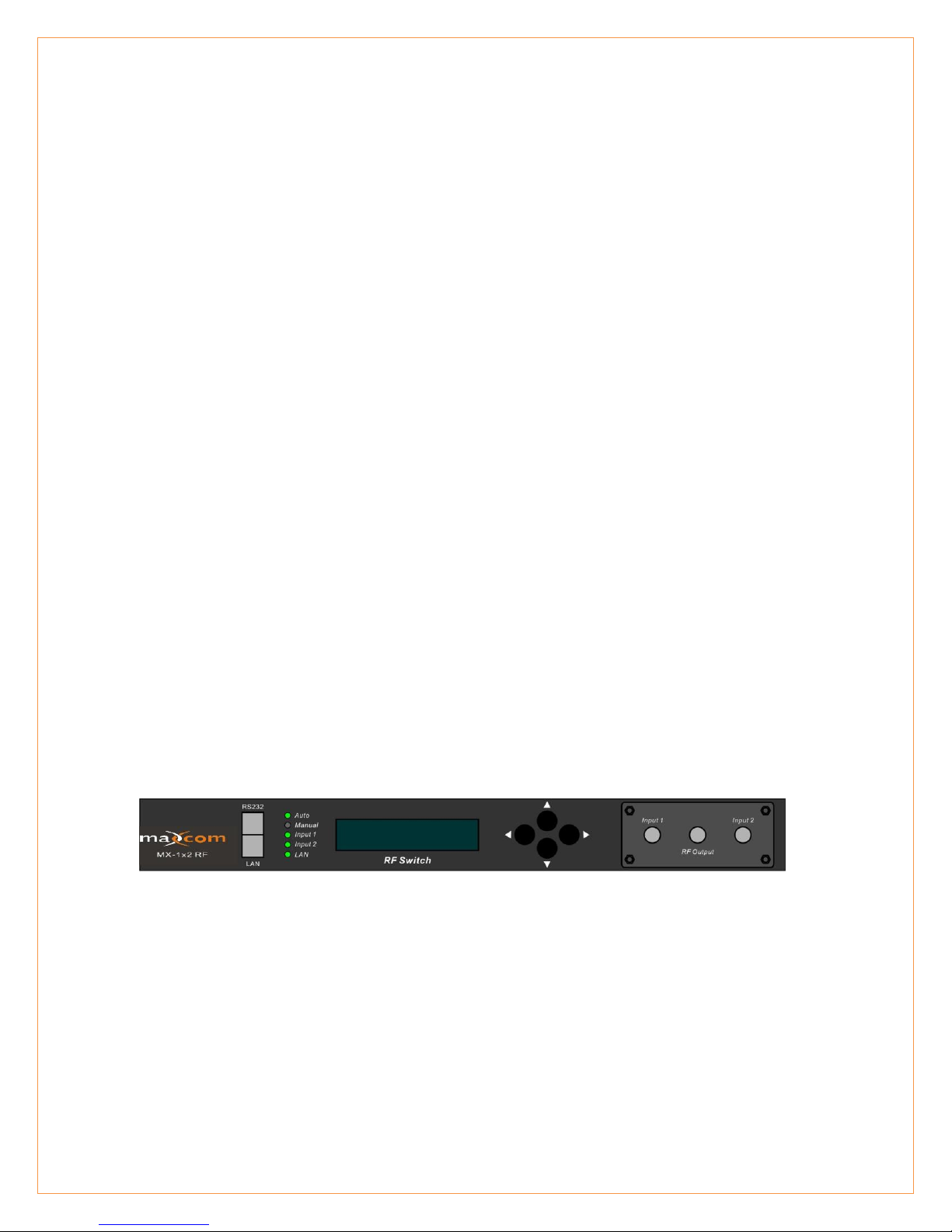
This section of the manual will give an overview of the available menus in the MX series
RF switch and their descriptions. All instructions in Section 2.0 refer to the
representation of the front panel shown in the diagram below. The user scrolls through
the menus using the push bottoms found on the front panel, these are located just to
the right of the LCD screen.
Shown with RF ports on front panel for display purposes
2.1 Operation of the control panel
2.1.1 Open menu
A. Plug in 110V power supply
B. Turn on power switch located on the rear panel
Front panel will illuminate and show “Model”
Page 3

2.1.2 Start-up main menu
Press \ button to display below menu in sequence.
Menu # 1 - Descriptor
Read-only menu, indicates the model of this unit
Menu # 2 - S/N
Read-only menu, indicates the serial-number
Menu # 3 - Date Code
Read-only menu, indicates the date code
Menu # 4 - Switch Type
Read-only menu, indicates the RF switch type
Menu # 5 - Switch Mode
Adjustable list, indicates the current RF switch mode (may select
automatic or may select input 1 or 2 manually)
Menu # 6 - Switch point
Adjustable list, indicates the subordinate channel RF switch point in dBuV
(please see dBuV to dBmV conversion chart for reference). This setting
allows you to select the minimum RF input threshold. If one of the inputs falls
below this level, the unit is designed to switch to the alternative input.
Menu # 7 - RF input 1
Read-only menu, indicates the channel 1 RF detection in dBuV (please see
dBuV to dBmV conversion chart for reference).
Menu # 8 - RF input 2
Read-only menu, indicates the channel 2 RF detection in dBuV (please
see dBuV to dBmV conversion chart for reference).
Menu # 9 - RF output
Read-only menu, indicates the RF output in dBuV (please see dBuV to
dBmV conversion chart for reference).
Menu # 10 - System Temp
Read-only menu, indicates the casing temperature
Menu # 11 - +5V monitor
Read-only menu, indicates the +5V voltage monitor
Menu # 12 - -5V monitor
Read-only menu, indicates -5V voltage monitor
Menu # 13 - +24V monitor
Read-only menu, indicates +24V voltage monitor
Menu #1 - IP
Adjustable list, display the IP address of SNMP
Page 4

Menu #2 - Sub
Adjustable list, display the address of net mask
Menu #3 - GateWay
Adjustable list, display the gateway address of SNMP
Menu #4 - TRAP1
Adjustable list, display the TRAP1 address of SNMP
Menu #5 - TRAP2
Adjustable list, display the TRAP2 address of SNMP
2.1.3 Menu assistant manual
1. Press the right button to display each parameter
show parms
2. Stage 1 menu: Press left button to display previous menu, press the
right button to display next menu, press the UP button to go back to
the main menu, pressing the DOWN button is invalid (not used).
last exit next
3. Stage 2 menu: Press left button to display former menu, press the
right button to display the next menu, press the UP button to go back
the main menu, press DOWN button to set the submenu.
last exit edit next
4. Stage 3 menu: Press left button to display current value minus 1,
press right button for current value plus 1, press UP button to cancel
the setting, press the DOWN button to save and exit the submenu.
dec cancel save inc
Shown with RF ports on front panel for display purposes
When the Switch Mode is selected as “Automatic State”, the input power on main
channel will typically be the one running at a higher RF level and will be the primary
output. If the main input is lower than the switch point power defined, and the input
power on subordinate channel is higher than the switch point power defined, then the
unit should switch the output from the secondary input
When the Switch Mode is selected as “Manual: Input 1 out; Input 2 out”, select the
desired channel output.
Page 5

dBuV
dBmV
dBuV
dBmV
dBuV
dBmV
dBuV
dBmV
50
-10 70
10 90
30 110
50
51
-9 71
11 91
31 111
51
52
-8 72
12 92
32 112
52
53
-7 73
13 93
33 113
53
54
-6 74
14 94
34 114
54
55
-5 75
15 95
35 115
55
56
-4 76
16 96
36 116
56
57
-3 77
17 97
37 117
57
58
-2 78
18 98
38 118
58
59
-1 79
19 99
39 119
59
60
0 80
20 100
40 120
60
61
1 81
21 101
41 121
61
62
2 82
22 102
42 122
62
63
3 83
23 103
43 123
63
64
4 84
24 104
44 124
64
65
5 85
25 105
45 66
6 86
26 106
46 67
7 87
27 107
47 68
8 88
28 108
48 69
9 89
29 109
49
dB Conversion Chart
*Note that RF levels shown in dBmV are 60dB lower that levels shown in dBuV
www.maxcomcorp.com
877-330-5333
 Loading...