

Page 1
MAXCOM PRODUCT SPECIFICATIONS
Description
The rack-mountable MX3257HD fiber optic video
multiplexer is ideal for transmitting 1 channel of video, 2
channels of audio and 1 high speed serial data channel
on one fiber optic cable.
The high speed serial data channel may be either DVBASI or SMPTE-310M. The MX3257HD’s High Speed
Serial data channel employs automatic cable
equalization for error free operation over long coaxial
cable runs.
The MX3257HD operates by digitizing and multiplexing
video, audio and high speed data onto a high-speed
serial data stream, which is then transmitted via fiber
optics.
Because the system employs digital transmission
techniques, performance characteristics are consistent
and maintained over the specified distance with no
degradation of signal.
The MX3257HD is designed to work with standard
singlemode or multimode fiber optic cable and can be
wall mounted or rack mounted. Both transmitter and
receiver come equipped with internal power supplies.
Optical Link LEDs facilitate the continuous monitoring of
the fiber optic system.
FIBER OPTIC VIDEO / AUDIO / ASI LINK
Model MAX3257HD
Model Selection Guide
Model
Description
MX3257HDT-1S-1V-2A-ASI-SCA-40
Fiber Optic Mux TX, 1 Video, 2 Audio, 1 DVB-ASI, Singlemode, SC/APC Connector, 40 Km
MX3257HDR-1S-1V-2A-ASI-SCA-40
Fiber Optic Mux RX, 1 Video, 2 Audio, 1 DVB-ASI, Singlemode, SC/APC Connector, 40 Km
MX3257HDT-1S-1V-2A-S310-SCA-40
Fiber Optic Mux TX, 1 Video, 2 Audio, 1 SMPTE-310, Singlemode, SC/APC Connector, 40 Km
MX3257HDR-1S-1V-2A-S310-SCA-40
Fiber Optic Mux RX, 1 Video, 2 Audio, 1 SMPTE-310, Singlemode, SC/APC Connector, 40 Km
MX3257HDT-1S-1V-2A-ASI-SCA-80
Fiber Optic Mux TX, 1 Video, 2 Audio, 1 DVB-ASI, Singlemode, SC/APC Connector, 80 Km
MX3257HDR-1S-1V-2A-ASI-SCA-80
Fiber Optic Mux RX, 1 Video, 2 Audio, 1 DVB-ASI, Singlemode, SC/APC Connector, 80 Km
MX3257HDT-1S-1V-2A-S310-SCA-80
Fiber Optic Mux TX, 1 Video, 2 Audio, 1 SMPTE-310, Singlemode, SC/APC Connector, 80 Km
MX3257HDR-1S-1V-2A-S310-SCA-80
Fiber Optic Mux RX, 1 Video, 2 Audio, 1 SMPTE-310, Singlemode, SC/APC Connector, 80 Km
Other Connectors and Distances Available Upon Request
Features
High Quality 10 Bit Digital Sampling of Video Input
High Speed Data Channel for DVB-ASI or SMPTE-310M
High Speed Data Channel employs Automatic Cable Equalization
Digital Transmission of Stereo Audio
Baseband Video or composite Video/Audio Transmission over video channel
External Audio Compatible with Balanced or Unbalanced Audio Formats
High Quality Uncompressed Digital Transmission
67 dB SNR
Page 2
OPTICS
90 - 240 VAC
47 - 63 Hz
Video Audio SC
+ I + I
G
G
1
2
+ I + I
G
G
3
4
Audio
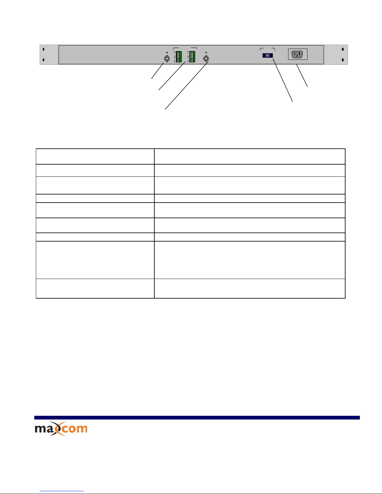
Rear Panel
Standards
NTSC, PAL, SECAM
Channels
(1) Video, (2) Audio & (1) High Speed Data
Video Bandwidth
SNR / dP / dG
10 Hz to 6.5MHz
67 dB, < 1 deg / < 1%
Video I/O
BNC, 1V p-p, 75 Ohm
High Speed Data
BNC, 1V p-p, 75 Ohm
DVB-ASI @ 270Mbps, SMPTE-310M @ 19.4 Mbps
Stereo Audio I/O
Terminal Block, 1Vp-p, 10 KOhm
Physical Dimensions
17” x 1.75” x 10”
Environment
Temperature: Operating: 0C to 50C
Storage: -20C to 70C
Humidity:
Operating: 10% to 90% RH
Storage: 5% to 90% RH
Input Power Requirements:
Voltage: 90 – 240 VAC, 47- 63 Hz
2248 Meridian Ste H
Minden, Nv. 89423
1-877-330-5333
WWWWWW..MMAAXXCCOOMMCCPPRRPP..CCOOM
M
Package Includes
Transmitter or Receiver (Must be purchased separately
Power Cord
Rack-mountable hardware
Easy to follow owner's manual
Warranty
5 year limited warranty
Video I/O: BNC, 75 Ohm
Stereo Audio Terminal Block, 10K Ohm
AC Power Input
Optical I/O
SC/PC or SC/APC
High Speed Data Channel: BNC, 75
Ohm
- DVB-ASI (270Mbps Transport)
Page 3
User’s Manual
MAX3257HD Series
Video / Audio Fiber Optic Multiplexing System
Installation and User Guide
Page 4

3257 HD Series User’s Manual No: UM-3257-D2
Page 2
TABLE OF CONTENTS
1 SAFETY INSTRUCTIONS
2 INTRODUCTION
2.1 System Description
2.2 Front Panel Indicator Description
2.3 Rear Panel Indicator Description
3 INSTALLATION
3.1 General Installation
3.2 Power Connection
3.3 Fiber Optic Cables Connection
3.4 Video Connections
3.5 Audio Connections
3.6 Balanced Audio Connections
3.7 Unbalanced Audio Connections
3.8 External Audio Sub-Carrier Connections
3.9 DVB-ASI Connections
4 OPERATION
Page 5

3257 HD Series User’s Manual No: UM-3257-D2
Page 3
1 SAFETY INSTRUCTIONS
THE 3257 SYSTEM MAY CONTAIN A CLASS IIIb LASER. PLEASE OBSERVE THE
FOLLOWING SAFETY PRECAUTIONS THAT APPLY TO LASER EQUIPPED UNITS.
WARNING: Do not disconnect the fiber optic external connector with the power turned
on. Exposure to Class IIIb Laser radiation is possible when the external fiber connector
is disconnected while the unit is still powered up. Ensure the rubber boot is in place
whenever the fiber optic cable is disconnected.
CAUTION: Attempting to make adjustments or performing operations other than those
specified may result in hazardous radiation exposure. Exposure for only seconds can
cause permanent eye damage as well as other injuries.
Page 6

3257 HD Series User’s Manual No: UM-3257-D2
Page 4
2 INTRODUCTION
2.1 System Description
The 3257 HD Series is a Video / Audio / DVB-ASI fiber optic multiplexer. The 3257 Series
Video modules can be configured to transmit simplex or duplex video &
Audio and 1 to 4 DVB-ASI signals using WDM technology. Depending on the distance requirements
between sites, the 3257s may be equipped to operate over multimode or single mode fiber. Distances
between the transmitter and receiver can be up to 3 Km for multimode operation and up to 120 Km for
single mode operation
.
SYSTEM I/O CONFIGURATION
Each of the four ports can be configured for one of the following options:
Simplex Video and Simplex Audio – 2 Channels
Simplex Video and Simplex Audio – 4 Channels
Simplex Video and Simplex Audio – 6 Channels
Simplex Video and Simplex Audio – 8 Channels
DVB-ASI – 1 to 4 channels
VIDEO / AUDIO TECHNOLOGY:
The 3257 system uses uncompressed 10 bit analog to digital modulation techniques which
provides excellent video quality. The audio circuitry also digitizes the audio signals prior
to transmission. The 2 channels of audio may be used for stereo audio or for two separate
channels of audio.
DVB-ASI Transmission Technology
The ASI option on the 3257HD series will accept any PCM 1Vp-p, 75 ohm
signal up to 600Mbps. The digital electrical signal connected to the BNC connectors is
converted to an optical signal. The ASI circuit’s receiver takes the incoming optical signal and
converts it back to electrical I/O: 75 Ohm up to 1Vp-p. The interface will NOT accept bipolar
signals, such as T1, T3, E1 or E3.
Page 7

3257 HD Series User’s Manual No: UM-3257-D2
Page 5
Models Numbers:
3257HD-AB-NA-NASI-CCC-DD
3257T:
1 Channel Video/ 2 Channel Audio Transmitters.
3257TSC:
1 Channel Video / 1 Channel Audio Sub-Carrier Transmitter
3257R:
1 Channel Video Receiver
3257RSC:
1 Channel Video / 1 Channel Audio Sub-Carrier Receiver
3257D:
1 Channel Duplex Video / 2 Channel Audio
A Fiber Count, 1 = single fiber, 2 = two fiber
B Fiber Type M = Multimode, S = Singlemode
NA
Additional Audio, N = # of Audio (2, 4, 6 )
NASI
Number of ASI interfaces: N = 1 to 4
CCC
Fiber Connection Type,
SC = SC/PC
SCA = SC/APC
FC = FC/PC
DD
Optical Transmission Distance in kilometres
Page 8

3257 HD Series User’s Manual No: UM-3257-D2
Page 6
Po we r
Lin k
Statu s
MAXCOM
2.2 Front Panel Indicators
The following diagram depicts the front panel indicators:
Link Indicator (Lights OFF):
TX – Problem with Transmitter
RX – Problem with Optical Link
Power Indicator
Link Indicator (Lights ON):
TX – Transmitter status is OK
RX – Optical Link is OK
Page 9

3257 HD Series User’s Manual No: UM-3257-D2
Page 7
2.3 Rear Panel Indicators
The following diagram depicts the 3257T and 3257R rear panel configuration
with optional audio channels installed:
NOTE: Model Depicted is configured with 1 Video 8 Audio and 4 ASI Channels
Page 10

3257 HD Series User’s Manual No: UM-3257-D2
Page 8
90 - 240 VAC
47 - 63 Hz
0
1
FUSE
3 INSTALLATION
3.1 General Installation
The units may be shelf mounted, 19” EIA rack mounted or table mounted. In
order to mount the units in an 19” rack, the Rack Mount Brackets must be first
installed by mounting the brackets to the mounting holes in the sides of the
3257.
Make sure that there is enough space to pull and connect both the electrical
data and optical cables without stressing them beyond the manufacturer’s
limitation strain specifications or exceeding the cable’s minimum bend radius.
3.2 Power Connection
The 3257 Series is compatible with 90 - 240 VAC power, 47Hz – 63Hz.
The Power Entry Module incorporates an IEC 3 prong power input connector, a switch
and a fuse holder, shown below:
IEC 3 Prong Power Input
Power Entry Module
Fuse Holder
On / Off
Switch
Page 11

3257 HD Series User’s Manual No: UM-3257-D2
Page 9
+ I + I
G
G
1
2
+ I + I
G
G
3
4
+ I + I
G
G
5
6
+ I + I
G
G
7
8
Audio
Video
3.3 Fiber optic cable connection
Verify that the fiber cable meets the 3257 Series’ transmission requirements.
Relevant cable specifications include loss, distance (dispersion) and return
loss.
3.4 Video Connections
Video signals are sent over a 75 ohm coax cable terminated in a BNC
connector (e.g. RG 59U with a BNC connector)
a. At the TX end (3257T), connect the video source to the VIDEO BNC
connector.
b. At the RX end (3257R), connect the VIDEO BNC to monitor. The output video
level may be adjusted by using a small screwdriver to turn the screw above the
output video connector, as shown below:
Video Output Level Adjust (RX only)
Video INPUT/ OUTPUT Connector:
75 Ohm, BNC
Page 12

3257 HD Series User’s Manual No: UM-3257-D2
Page 10
+ I + I
G
G
1
2
+ I + I
G
G
3
4
+ I + I
G
G
5
6
+ I + I
G
G
7
8
Audio
Video
3.5 Audio Connection
The 3257 Models have either simplex or duplex audio. The 3257 supports both
balanced audio and unbalanced audio. Accessing the audio I/O requires connecting
to one or both channels of audio. The audio input and output impedance is 10Kohms.
The Audio Terminal Block on the Video/Audio module provides the connectivity for
transmitting and receiving audio. The illustrations below show how to connect
balanced and unbalanced audio:
3.6 Balanced Audio (Differential)
For Balanced audio connections, connect the audio “+” lead to the respective audio
channel “+” input and the “-“lead to the audio channel “-‘lead, as shown below.
Balanced Audio Input
Audio Channel 1, 3, 5, 7
Connect Ground to TB Pin 1
Connect Input + to TB Pin 2
Connect Input – to TB Pin 3
Audio Channel 2, 4, 6, 8
Connect Input + to TB Pin 4
Connect Input – to TB Pin 5
Connect Ground to TB Pin 6
Balanced Audio Output
Audio Channel 1, 3, 5, 7
Connect Ground to TB Pin 1
Connect Input + to TB Pin 2
Connect Input – to TB Pin 3
Audio Channel 2, 4, 6, 8
Connect Input + to TB Pin 4
Connect Input – to TB Pin 5
Connect Ground to TB Pin 6
Page 13

3257 HD Series User’s Manual No: UM-3257-D2
Page 11
+ I + I
G
G
1
2
+ I + I
G
G
3
4
+ I + I
G
G
5
6
+ I + I
G
G
7
8
Audio
Video
3.7 Unbalanced Audio (Single Ended)
For Unbalanced audio connections, connect the audio I/O to the respective “+” and
“GND“leads on the output audio connector, as shown below.
Note: Unbalanced Audio output will be 3dB less than input
Note: DO NOT connect the (-) lead to ground on the audio OUTPUT as this may
create noise on the ground, which may distort the video signals.
Unbalanced Audio Input
Audio Channel 1, 3, 5, 7
Connect Ground to TB Pin 1
Connect Input + to TB Pin 2
Audio Channel 2, 4, 6, 8
Connect Input + to TB Pin 4
Connect Ground to TB Pin 6
Unbalanced Audio Output
Audio Channel 1, 3, 5, 7
Connect Ground to TB Pin 1
Connect Input + to TB Pin 2
Audio Channel 2, 4, 6, 8
Connect Input + to TB Pin 4
Connect Ground to TB Pin 6
Page 14

3257 HD Series User’s Manual No: UM-3257-D2
Page 12
3.8 External 4.5Mhz Audio Sub-Carrier
The 3257 Series also includes an option for transmitting video, audio and a 4.5 MHz audio
sub-carrier as an external signal. The figure below depicts the 3257 set up with video, 4
channels of Baseband audio and an external audio sub-carrier channel. The audio sub-carrier
channel uses a BNC connector with 75 ohm impedance.
+ I + I
G
G
1
2
+ I + I
G
G
3
4
AudioVideo
Audio SC
Video I/O
BNC
75 Ohm
Baseband Audio I/O
External Audio Sub-Carrier I/O
BNC Connector
75 Ohm
Page 15

3257 HD Series User’s Manual No: UM-3257-D2
Page 13
3.9 DVB-ASI Connections
DVB-ASI signals are sent over a 75 ohm coax cable terminated in a BNC
connector (e.g. RG 59U with a BNC connector) The DVB-ASI I/O will accept ANY PCM signal
from 1Mbps to 600Mbps that is less than 1Vp-p and is compatible with 75 ohm terminations.
The DVB-ASI connection is NOT compatible with T-3 (DS3), T1 (DS1), or any bipolar signal.
Page 16

3257 HD Series User’s Manual No: UM-3257-D2
Page 14
4 Operation
Turn-On Procedure
To operate the 3257 video transmission system:
1. Install the 3257 units to the appropriate power supply using the power entry
module to provide power via an IEC 3 prong cable.
2. The indicator “POWER” on the front panel shows that the unit is properly
powered.
3. Install the fiber optic cables to the 3257
4. Verify that the LINK lights are illuminated. This indicates that the unit has a
good optical link.
5. Connect the Video and Audio Input and Output Signals
Verify that the video and audio is being received properly.
 Loading...