

Page 1
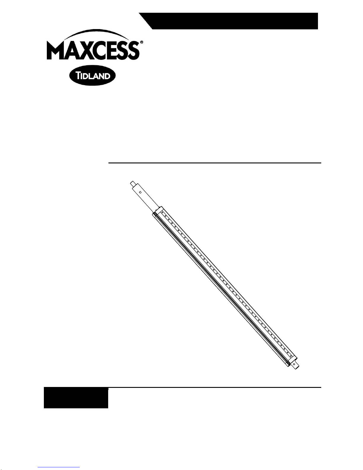
Tidland Series 950/960
Slitter Shaft
Installation, Operation and Maintenance
EN
Series 950 GK
Series 960 GR
MI 27L666264 1 J
TIDLAND SLITTING SOLUTIONS
Page 2

IMPORTANT SAFETY INSTRUCTIONS
www.maxcessintl.com
Tidland GK/GR Slitter Shaft
MI 27L666264 1 J
Page 2
When using this Tidland product, basic safety precautions should always be followed to
reduce the risk of personal injury. Your company's safety instructions and procedures should
always be followed. When using this product with any other equipment or machinery, all
safety requirements stipulated by that equipment or machinery manufacturer must be
followed. Compliance with local, state, and federal safety requirements is your responsibility.
No part of these or the following instructions should be construed as conflicting with or
nullifying the instructions from other sources. Be familiar with the hazards and safety
requirements in your work environment and always work safely.
1. Read and understand all instructions and shaft design application limits before
operation.
2. Never use this product for a purpose or in a machine that it was not specifically designed
for. See Product Safety Data Sheet (PSDS), if applicable.
3. Do not exceed the operation loads for this shaft as noted on its PSDS, Product Safety
Data Sheet, if applicable.
4. Follow all warnings and instructions marked on the product and on the PSDS, if
applicable.
5. Inspect the shaft for wear and/or other safety and functional deficiencies daily, before
each use.
6. Wear safety glasses or proper eye protection when inflating or deflating or otherwise
operating the air system, if applicable.
7. Do not remove or otherwise alter any setscrews or fastening devices prior to using this
product.
8. Do not operate this product if any setscrews or fastening devices are missing.
9. Do not lift shaft manually if it is beyond your capacity. Loads over 1/3 your body weight
may be prohibitive. Consult your company safety policy.
10. When lifting a shaft, use proper lifting techniques, keeping back straight and lifting with
the legs.
11. Do not carry or lift this product over wet or slippery surfaces.
12. Use appropriate mechanical lifting devices, such as a hoist or shaft puller, for heavier
shafts.
13. When performing maintenance or repair procedures, if applicable, do not pressurize the
shaft if journal setscrews are loose or missing.
14. When performing maintenance procedures, if applicable, do not pressurize the shaft if
the journal is missing.
15. All replacement parts used on this product should be made to original Tidland
specifications.
16. All maintenance and repair procedures performed on this product should be done to
Tidland specifications by qualified personnel.
Page 3

TABLE OF CONTENTS
www.maxcessintl.com
Tidland GK/GR Slitter Shaft
MI 27L666264 1 J
Page 3
Caution .................................................................................................................................................... 3
Customer Service .................................................................................................................................... 3
Recommended Tools .............................................................................................................................. 3
Shaft Notes .......................................................................................................................................... 5
Install Anvil Rings (Initial Setup).......................................................................................................... 5
Lock Anvil Rings in Place .................................................................................................................... 5
To Reposition Anvil Rings ................................................................................................................... 6
To Remove and Replace Anvil Rings ................................................................................................. 7
Maintenance Schedule ........................................................................................................................ 8
Daily ................................................................................................................................................ 8
Weekly ............................................................................................................................................ 8
Centering Bars .................................................................................................................................... 8
Rubber External Elements .................................................................................................................. 9
Important Notes (Read First) .......................................................................................................... 9
To Remove Rubber Elements ........................................................................................................ 9
To Replace Rubber Elements ....................................................................................................... 10
CAUTION
Wear eye protection when using tools or compressed air.
Tidland Slitter Shafts are designed to hold anvil rings in place during
slitting operations.
Knife blades and anvil rings are sharp! Avoid injury— always wear
stainless steel protective gloves when handling blades.
Do not operate the shaft when the elements are not inflated.
CUSTOMER SERVICE
1.360.834.2345 www.maxcessintl.com
1.800.426.1000
RECOMMENDED TOOLS
Clean, non-lubricated air supply with regulator: 80-120 psi (5.5-8.3 bar)
See page 5 for operating air pressure.
Tidland Inflation Tool (Part No. 128052: for use with fixed valves only)
Tidland Air Release Tool (Part No. 111630: for use with fixed valves only)
Tidland Hole Punch and Hole Locator Kit (Part No. 133162)
Stainless Steel Protective Gloves (Part No. 132084)
Hex drive wrench kit (Part No. 128363: L-Handle; 1.5, 2, 2.5, 3, 4, and 5 mm)
(Part No. 132146: T-Handle; 2.5, 3, 4, 5, and 6 mm)
Wet/dry sandpaper – 600 grit (for removing small scratches and burrs from shaft body)
Parker Super O-Lube O-ring Lubricant (make no substitutions)
Loctite
For more accessories to help with your slitting process, visit www.maxcessintl.com.
®
222 (or equivalent low-strength threadlocker)
Page 4
ASSEMBLY DIAGRAM AND PARTS LIST
www.maxcessintl.com
Tidland GK/GR Slitter Shaft
MI 27L666264 1 J
Page 4
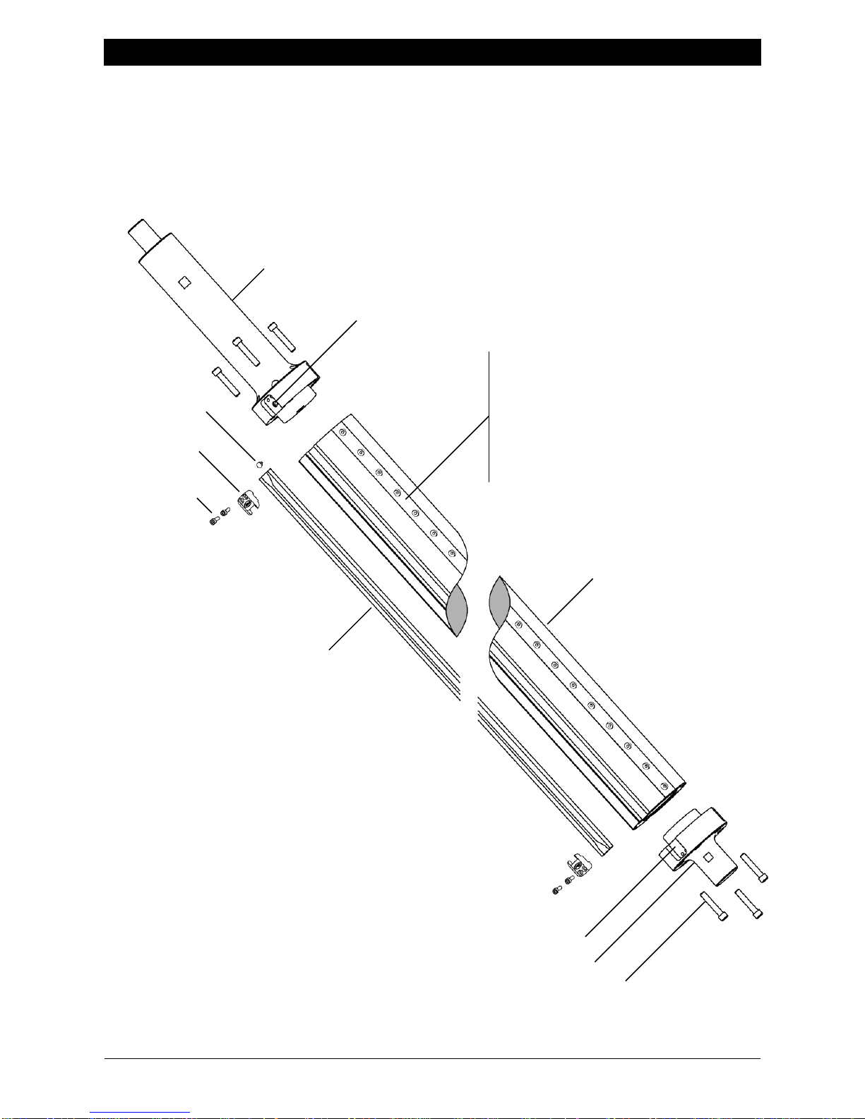
VALVE JOURNAL
RUBBER ELEMENT
135063
ELEMENT END CLAMP POCKET
NON-VALVE JOURNAL
SOC HD CAPSCREW
SHAFT BODY
ELEMENT END CLAMP
132445
SOC HD CAPSCREW
132583
M5 X 16 mm
AIR FITTING
562024
BARB FITTING (516618)
WITH O-RING (126193)
SERIES 960 (GR) ONLY
CENTERING BAR – DO NOT REMOVE
The centering bars are machined on the shaft
to meet your specifications. Bars must be
removed and replaced only at a Tidland facility
to guarantee that the shaft operates as
designed, and to maintain your warranty.
Call for assistance.
Series 950GK/960GR configurations vary. The shaft shown here features removable
journals: it may also be manufactured as a one-piece shaft design.
Call for assistance with part numbers for your shaft. Please have your shaft serial number
available when you call.
Page 5
INSTALLATION
www.maxcessintl.com
Tidland GK/GR Slitter Shaft
MI 27L666264 1 J
Page 5
HAND HAZARD
Knife blades and anvil rings are sharp.
Wear protective gloves when working with knife blades and anvil rings.
Tidland recommends stainless steel gloves.
Shaft Notes
Tidland Slitter Shafts are designed to hold anvil rings in place during slitting operations.
Install shaft as required for your specific application: you may need to install anvil rings
prior to shaft installation.
Before each operation, inspect the body and centering bars (Series 960 GR only) for
scratches that may prevent the anvil rings from moving freely along the shaft.
Any large burrs or scratches on the shaft or centering bars must be removed.
Use 600 grit wet/dry sandpaper to smooth out the surface.
Heavily gouged or deformed centering bars should be replaced.
Call for assistance.
Install Anvil Rings (Initial Setup)
1. Complete your company lockout/tagout procedures to lock out system power.
2. Wear protective gloves when working with knife blades and anvil rings. Tidland
recommends stainless steel gloves.
3. Make sure that the shaft is clean and dry and that all screws securing the centering bars
(Series 960 GR only) are present and tight. Do not exceed 45 in·lbs (5.1 Nm) torque.
Overtightening will result in deformed centering bars.
4. Install the anvil rings (and spacers, if applicable), making sure that sharpened edges are
toward the slitting sides of the knife blades.
Note: Standard Tidland anvil rings are reversible with dual slitting edges: otherwise, install
the anvil ring with the sharpened edge toward the slitting side of the knife blade.
5. Reverse lockout/tagout procedure to restore system power.
Lock Anvil Rings in Place
- To extend the life of the rubber elements, regulate incoming air supply to 55-65 psi
(3.8-4.5 bar) for normal operation.
- If rings are slipping, increase the air pressure as needed in 5 psi increments. Do not
exceed 80 psi. 5.5 bar.
Page 6
OPERATION
www.maxcessintl.com
Tidland GK/GR Slitter Shaft
MI 27L666264 1 J
Page 6
Do not inflate while shaft is rotating.
To Deflate Shaft
Do not deflate while shaft is rotating.
Use the Tidland Air Release Tool for fixed valve shafts.
Do not use finger to release air.
HAND HAZARD
Knife blades and anvil rings are sharp.
Wear protective gloves when working with knife blades and anvil rings.
Tidland recommends stainless steel gloves.
See your Tidland Knifeholder Manual for detailed knifeholder setup and operation.
To Reposition Anvil Rings
Follow your company safety procedure.
1. Stop shaft rotation. Deflate the shaft completely.
2. Ensure that the shaft is clean and dry.
3. Move the anvil rings (and spacers, if applicable) to the desired location.
4. To lock anvil rings in place, inflate shaft to 55-65 psi (3.8-4.5 bar). Do not exceed
maximum operating air pressure of 80 psi (5.5 bar).
5. See your knifeholder manual for setup at new anvil ring locations.
Page 7

MAINTENANCE
www.maxcessintl.com
Tidland GK/GR Slitter Shaft
MI 27L666264 1 J
Page 7
If using an air shaft with Tidland e-Knifeholder, do not adjust or remove the ball
detent set screws in the anvil rings. These are not fastening screws; they ensure
continuity between the shaft and the anvil ring, which is required for proper
operation of the e-Knifeholder.
To Remove and Replace Anvil Rings
Remove Anvil Rings
1. Stop shaft rotation.
2. Deflate shaft completely.
3. Complete your company lock-out procedures to lock-out system power.
4. Release the air from the slitter shaft using the air valve.
5. Slide the anvil rings along the slitter shaft toward the removable bearing.
6. To help ensure safety and avoid damage to the system, provide alternative support for the
slitter shaft before removing the bearing.
7. When slitter shaft is properly supported, remove bearing.
8. Remove anvil rings (and spacers, if applicable) by sliding them off the shaft through the
opening in the side frame.
9. Leave the shaft in a supported position.
Reinstall Anvil Rings
1. Slide the anvil rings (and spacers, if applicable) onto the shaft, making sure that
sharpened edges are toward the slitting sides of the knife blades.
Note: Standard Tidland anvil rings are reversible with dual slitting edges: otherwise, install
the anvil ring with the sharpened edge toward the slitting side of the knife blade.
2. Reinstall the removable bearing and remove the alternate shaft support.
3. Align knife blades with anvil rings.
4. See your knifeholder manual for repositioning and setup at new anvil ring locations.
5. Reverse your company lock-out procedures to unlock the system power.
6. To lock anvil rings in place, inflate shaft to 55-65 psi (3.8-4.5 bar). Do not exceed
maximum operating air pressure of 80 psi (5.5 bar).
7. Resume slitting operation.
Page 8

MAINTENANCE
www.maxcessintl.com
Tidland GK/GR Slitter Shaft
MI 27L666264 1 J
Page 8
NOTICE
Petroleum-based products will damage the inflation elements.
Do not use.
Maintenance Schedule
Daily
Throughout the operation shift, use compressed air to keep shaft free from dust and debris.
Use a mild solvent, rubbing alcohol, to remove any residue. Dry shaft thoroughly.
Weekly
Watch for debris buildup along the external elements that might prevent proper expansion of the
element. If necessary, remove the elements from the shaft and perform a thorough cleaning
(page 9).
Centering Bars
(Series 960 GR shafts)
The centering bars, made from Acetron® GP Acetal (a general purpose copolymer), help ensure
accurate positioning for your anvil rings.
Keep the bars and the shaft free from grit and scratches so that the anvil rings slide smoothly
along the length of the shaft.
Small burrs, scratches and deformities can be smoothed out using 600 grit wet/dry sandpaper.
Large gouges or deformities may require replacement of the centering bars. Call for assistance.
Do not remove the centering bars. The centering bars are machined on the shaft to meet your
specifications. Bars must be removed and replaced only at a Tidland facility to guarantee that
the shaft operates as designed, and to maintain your warranty.
Page 9
MAINTENANCE
www.maxcessintl.com
Tidland GK/GR Slitter Shaft
MI 27L666264 1 J
Page 9
NOTICE
Petroleum-based products will damage the inflation elements.
Do not use.
RUBBER ELEMENT
HOLE PUNCH TOOL
Fig. 1
Fig. 2
Fig. 3
Rubber External Elements
Important Notes (Read First)
The external expansion element material is ethylene propylene diene
monomer (EPDM), a synthetic rubber.
The elements can be replaced without removing the shaft from the machine.
Do not remove the aluminum T-slot extrusion from shaft when replacing the element.
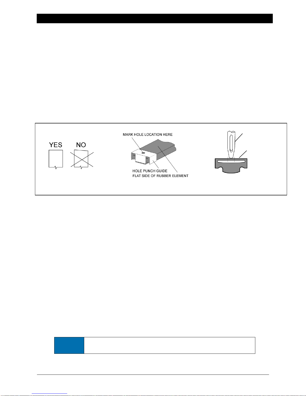
Cut elements square across the ends so there is a flush fit at the end clamp.
Elements cut at an angle are at risk for leaks. (Fig. 1)
Use the Tidland Hole Punch Guide to mark the location of the air fitting hole on the
element. (Fig. 2)
Use the Tidland Hole Punch to punch holes for air fittings in the rubber element.
Punch the hole in the bottom wall only of the element. (Fig. 3)
Make sure that the element end clamps completely cover the ends of the elements.
To check for leaks after replacing elements, inflate shaft to operating pressure, spray
element end clamps with soapy water and check for bubbles.
There are many configurations for the Tidland Series 950GK/960GR shaft air systems,
some of which include the use of a side valve and air hoses. If your shaft is equipped with
a non-rotary union (fixed) valve, see page 1.
To Remove Rubber Elements
1. Release all air from the shaft and disconnect the air supply.
2. Remove the socket head capscrews from the element end clamps and remove the
clamps. (4 mm hex drive)
3. At the valve end of the shaft, carefully pry up the rubber element. Ensure that the barb
fitting with the o-ring stays in the shaft.
4. Remove the element from the slot. Do not remove the T-slot extrusion from the shaft.
5. Remove the air fitting "head" from the old rubber element.
6. Clean the shaft and slot thoroughly with a mild solvent, such as rubbing alcohol. Dry slot
and shaft thoroughly.
Page 10
MAINTENANCE
www.maxcessintl.com
Tidland GK/GR Slitter Shaft
MI 27L666264 1 J
Page 10
3/8" (9.53mm)
Fig. 6
SOC HD CAPSCR
RUBBER ELEMENT
ELEMENT END CLAMP
AIR HOSE
(FOR USE WITH FIXED VALVES)
O-RING
AIR FITTING
BARB FITTING
5/16" (7.93mm)
Fig. 4
Fig. 5
To Replace Rubber Elements
Bladder material supplied for replacement may be longer than the required finished length.
Do not cut to length until instructed.
Start at the Valve End
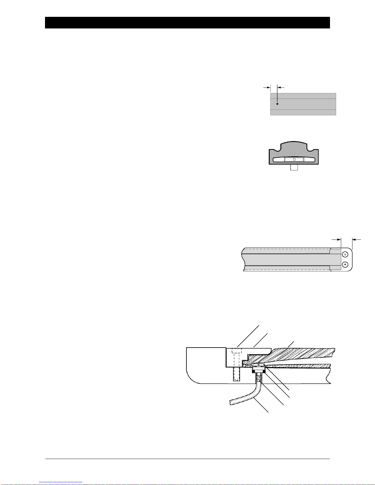
1. Square off one end of the element. (Elements cut at an angle
are at risk for leaks.)
2. At the squared end of the element, mark the location of the
air fitting hole (Fig 4). Center the mark on the flat side of the
element 5/16 " (7.93 mm) from the end, or use the
recommended hole locator guide. (Page 9, Fig 2)
3. With the Tidland Hole Punch Tool, punch a hole in the
bottom wall only of the element. (Page 9, Fig 3)
4. Insert air fitting "head" into the hole in the element wall. (Fig. 5)
5. Starting at the valve end of the shaft, push the non-valve end of
the element into and through the length of the shaft slot. Use
silicone dry lubricant spray to ease installation, if necessary.
6. At the valve end of the shaft, connect the air fitting with the barb fitting in the shaft.
7. Apply a small amount of Loctite 222 to the end clamp screw threads and install the valve
end clamp, securing the element underneath it.
8. Using 4 mm hex wrench, tighten end clamp screws to 55-60 in·lbs (6.21-6.77 Nm).
9. At the non-valve end of the shaft, mark the rubber element
at a point 3/8" (9.53 mm) from the outside end of the
element end clamp pocket. Do not stretch the element.
(Fig. 6)
10. Pull the end of the element out of the slot to cut it square
across the end at the mark, then push it back into the slot.
11. Apply a small amount of Loctite 222 to the end clamp screw threads and install the nonvalve end clamp, securing the element underneath it.
12. Using 4 mm hex wrench, tighten end clamp screws to 55-60 in· lbs (6.21-6.77 Nm).
If the element end clamp does not sit
flat in the pocket, the rubber element
may be too long. Remove the clamp
and trim off a small amount of the
element. Reinstall the clamp,
ensuring that the element is
completely secured underneath.
To check for leaks after replacing
elements, inflate shaft to operating
pressure, spray element end clamps
with soapy water and check for
bubbles.
Page 11
AIR CIRCUITS
www.maxcessintl.com
Tidland GK/GR Slitter Shaft
MI 27L666264 1 J
Page 11
Fig. 7b
Fig. 7a
Fig. 8
Note: Check air flow through hoses
during assembly. Hose kinking
can prevent inflation or deflation.
Your Tidland Series 950GK/960GR External Element shaft may be equipped with a fixed
valve.
In most cases, the air fitting at the end of each external element (underneath the element
clamp) attaches to a hose inside the shaft, which connects to a side or end valve.
For single circuit valves, internal hoses attach to separate barbs on a plug installed either
in the journal or on the side of the shaft. Air is delivered through the valve to the plug.
Some single circuit shafts have no hoses. Air is routed through drilled holes from the valve to
the air fittings under the rubber elements.
Isolation valves connect directly to the internal air hoses.
Maintenance for some air circuit hoses may require removal of shaft journals.
Hoses may feed out the end of the shaft into the journal or out the side of the shaft,
depending upon the type of valve used. Wrap a piece of tape around exposed hoses to
prevent them from slipping back inside the shaft body. (Journal removal may be required
to retrieve them otherwise.)
After removing an air fitting, always clip off the damaged end of an air hose before
reconnecting it to the fitting.
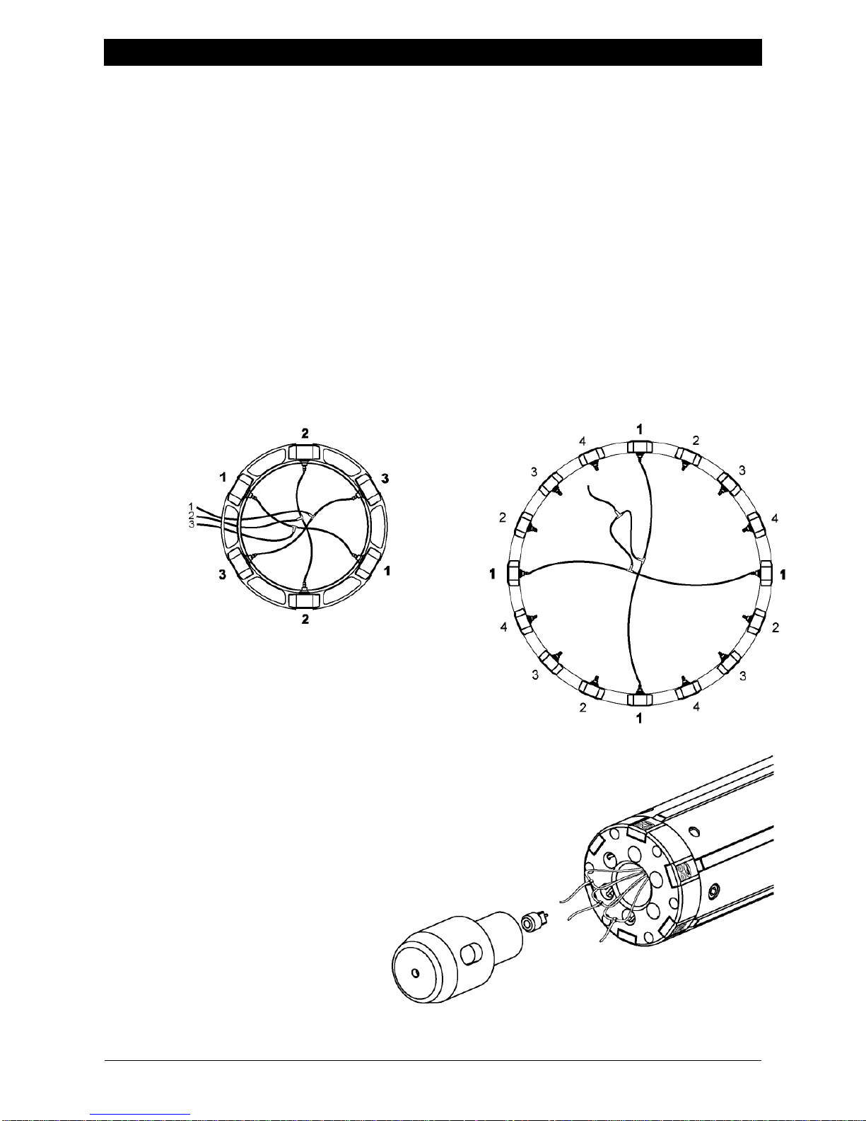
Fig . 7 – "T-barb" hose connections are made inside the shaft.
The number of connections depends upon how many
external elements the shaft has. All connections should
be made from opposing pairs of hoses and reduced to
the minimum number of pairs needed for the 3-way or
4-way valve used, as shown in Fig. 7a and 7b.
Fig . 8 – Hoses originating from end clamps in the shaft "head"
must feed back into the shaft body before feeding out
through the end of the shaft (to prevent being crushed
by the journal).
Page 12
www.maxcessintl.com
Tidland GK/GR Slitter Shaft
MI 27L666264 1 J
Page 12
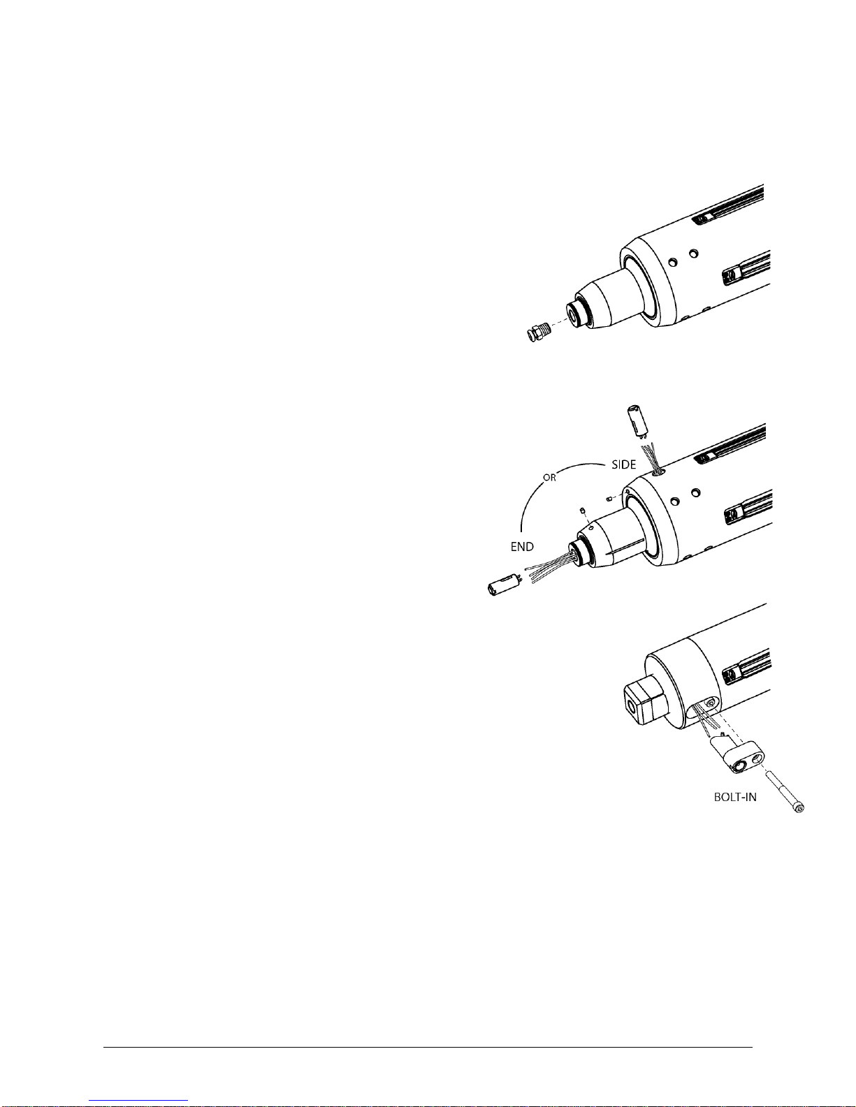
There are several styles of valves used on Tidland External Element shafts, installed
either in the end or the side of the shaft, depending on your application.
Ensure that the shaft is completely deflated before removing the valve.
To check for air leaks after reinstalling valves, inflate shaft to operating pressure, spray
valve with soapy water and watch for bubbles.
Non-Isolation Quick Release
Thin wall socket wrench: 7/16", 3/4" (may be required)
1. Use a socket wrench to unscrew the valve
from its side or end location in the shaft.
2. Apply thread sealant (according to manufacturer's
instructions) and install the valve.
Isolation Valve (3-way or 4-way)
End or Side Location
1. Remove set screw.
2. Pull valve from end carefully
and disconnect air hoses.
3. Cut off damaged ends of hoses.
4. Attach air hoses to new valve.
5. Reinstall valve in shaft.
6. Reinstall setscrew.
Side Location Bolt-in
1. Remove socket head bolt.
2. Pull valve from end carefully
and disconnect air hoses.
3. Cut off damaged ends of hoses.
4. Attach air hoses to new valve.
5. Reinstall valve in shaft.
6. Reinstall socket head bolt.
Before operation:
Check for proper inflation and deflation.
If there is a problem, check air hoses for kinks or disconnects.
See TROUBLESHOOTING on page 1.
Page 13

TROUBLESHOOTING
www.maxcessintl.com
Tidland GK/GR Slitter Shaft
MI 27L666264 1 J
Page 13
Problem
Possible Cause
Recommended Solution
Air Leak
Element end clamps not
tight
Tighten end clamps at both ends of shaft
to 55-60 in· lbs (6.21-6.77 Nm).
End clamps not centered
over element
Ensure that the end clamps completely
cover the end of the element. Element
must be cut square across its end in order
for the end clamp to make contact across
the full width of the element.
Hole for air fitting in element
is deformed
Remove end clamp and check the element
around the air fitting. If the hole is
deformed or the element is torn, replace
the element. Use the Tidland Hole Punch
Tool for best results when installing air
fittings in a new element.
Air hose connection to the
air fitting has failed.
Remove end clamps and confirm that the
air fitting is connected to the internal air
hose. Check that the fitting is seated
correctly in its hole.
Valve is leaking
Access the valve and confirm that air
hoses are attached. If valve is leaking from
the center, replace the valve.
External element
will not collapse
completely
Fiber or dust buildup in
element slot is causing
scraping along edges of slot
Clean along slot. If necessary, remove and
replace external element.
Cold flow of rubber element
Replace rubber element.
Reduce operating air pressure to
55-65 psi (3.8-4.5 bar).
Kinked internal air hoses
Check hose installation:
At air fittings under element end
clamps
At valve
In shaft body (may require journal
removal)
Elements difficult
to install
Buildup in slot
Clean slot with mild solvent, such as
rubbing alcohol, and dry thoroughly. Spray
slot and elements with dry silicone
lubricant.
External element
extrudes out of
slot
Element is over-lubricated
with dry silicone spray.
Remove element and wipe clean.
Reinstall, lubricating only as necessary.
Page 14

TROUBLESHOOTING
www.maxcessintl.com
Tidland GK/GR Slitter Shaft
MI 27L666264 1 J
Page 14
Problem
Possible Cause
Recommended Solution
Anvil rings do not
slide smoothly on
the shaft
Series 950: Shaft body may
be scratched.
Check shaft body for deep scratches or
burrs that may impede movement of
anvil rings. Remove scratches with 600
grit wet/dry sandpaper.
Series 960GR: Centering
bars loose, deformed or
damaged
Ensure that all hardware on the
centering bars is tight. (45 in·lbs)
(5.08 Nm)
Inspect centering bars for
scratches and gouges. Remove
damage or deformities with 600 grit
wet/dry sandpaper.
Heavily damaged or deformed bars
should be replaced. Contact
Maxcess. 1-800-426-1000
Anvil rings will not
fit on shaft
Element end clamps
extending beyond shaft
O.D.
Inspect element length under clamp.
If it is too long, it will push up on clamp.
Trim small amount from element and
reinstall clamp.
Anvil ring is slipping
Elements not gripping ring
Check inflation pressure.
Ensure that the external element is
expanding completely.
Check for leaks.
Check for worn elements.
Ensure correct ring size.*
e-Knifeholder not
operating correctly
Bad continuity between
shaft and anvil ring
Ensure that set screws are present in
the anvil rings.
Refer to the e-Knifeholder operation
manual to check continuity
requirements; adjust set screws to
achieve continuity.
Do not tighten set screws against the
shaft.
* Call for assistance with proper "ring to shaft" fit.
Visit the Repair and Return Center online to review our return policies
or to submit an electronic Return Material Authorization Request.
www.maxcessintl.com/returns
Page 15

Page 16

EUROPE, MIDDLE EAST
AND AFRICA
Tel +49.6195.7002.0
Fax +49.6195.7002.933
www.maxcess.eu
© 2016 Maxcess
 Loading...