

Page 1
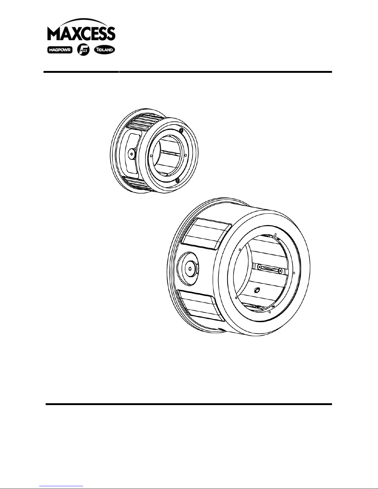
Raptor Series Adapters
Installation, Operation and Maintenance
3”-6” ADAPTER
6”-10” ADAPTER
For Air Powered Lug and Torque Chucks Adapter Sizes 3”– 5”
3”– 6”
3”– 6.75”
3”– 150mm
3”– 7.415”
3”– 8”
6”– 8”
6”– 10”
6”– 12”
Page 2

TABLE OF CONTENTS
Caution.................................................................................................................................... 3
Tidland Customer Service ....................................................................................................... 3
Recommended Tools .............................................................................................................. 3
3" Adapters.............................................................................................................................. 4
Assembly Diagram and Parts List........................................................................................ 4
Installation............................................................................................................................ 5
Operation............................................................................................................................. 5
Maintenance........................................................................................................................ 6
To Remove Adapter from Chuck ..................................................................................... 6
To Disassemble Adapter ................................................................................................. 6
To Reassemble Adapter.................................................................................................. 7
6" Adapters for Torque Chucks ............................................................................................... 8
Assembly Diagram And Parts List....................................................................................... 8
Installation............................................................................................................................ 9
Operation............................................................................................................................. 9
Maintenance...................................................................................................................... 10
To Remove Adapter from Chuck ................................................................................... 10
To Disassemble Adapter ............................................................................................... 10
To Reassemble Adapter................................................................................................ 11
6" Adapters for Air Powered Lug Chucks.............................................................................. 12
Assembly Diagram And Parts List..................................................................................... 12
Installation.......................................................................................................................... 13
Operation........................................................................................................................... 13
Maintenance...................................................................................................................... 14
To Remove Adapter from Chuck ................................................................................... 14
To Disassemble Adapter ............................................................................................... 14
To Reassemble Adapter................................................................................................ 15
Troubleshooting Raptor Series Chucks................................................................................. 16
Tidland Raptor Series Chuck Adapters 643236 1-800-426-1000
Installation, Operation and Maintenance
2
05/11 www.tidland.com
Page 3

CAUTION
WARNING
• Chucks with adapters installed can weigh up to 150 lbs.
• Use a hoist to install or remove chuck assembly.
Wear eye protection when using tools or compressed air.
TIDLAND CUSTOMER SERVICE
1-800-426-1000 www.tidland.com
Visit the Tidland Repair and Return Center online to review our return policies
or to submit an electronic Return Material Authorization Request.
www.tidland.com/returns
RECOMMENDED TOOLS
• Hex drive wrenches: 1/8", 3/16"
• LOCTITE
• Dow Corning Molykote
For more accessories to help with your winding processes, visit www.tidland.com.
Tidland Raptor Series Chuck Adapters 643236 1-800-426-1000
Installation, Operation and Maintenance
®
242
®
557 Silicone Dry Film Lubricant (Do not use grease.)
3
05/11 www.tidland.com
Page 4
(
)
3" ADAPTERS
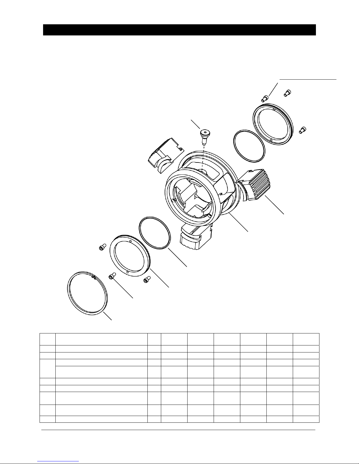
Assembly Diagram and Parts List
These adapters are installed only onto the Raptor Series 3" Torque or 3" Air Powered Lug
Chucks to run core size applications as listed below (+.010"/+.020"). Adapter installation can
be performed without removing the chuck from the machine.
3"- 5" – Part No. 622178
3"- 6" – Part No. 586289
3"- 6.75" – Part No. 652130
3"- 150mm – Part No. 629669
3"- 7.415"
3"- 8
–
Part No. 678591
–
Part No. 652736
3
Adapter weights range from
13-32 lbs.
6 OR
(3"-5" ADAPTER ONLY)
7
2
1
5
3"-6" ADAPTER SHOWN
(BODY AND LUG DESIGNS VARY SLIGHTLY)
4
6
FOR ALL SIZES EXCEPT 3"–5" ADAPTER
8 (3"–5" ADAPTER ONLY)
ITEM DESCRIPTION QTY
1 ADAPTER BODY 1 622173 586251 652101 629670 652723 652723
2 LUG 3 622174 586367 652127 629671 652572 683169
LOCKING PIN or 1 n/a 589333 589333 589333 652703 652703
3
SOC HD HALF DOG PT
.375"-16UNC X 1.00" LG (GRADE 8)
4 LUG RETAINER RING 2 561881 561881 561881 561881 561881 561881
5 O-RING (PARKER 2-235) 2 597579 597579 597579 597579 597579 597579
SOC HD CPSCR
6
1/4-20NC X .500" LG (GRADE 8)
BUTTON HD SOC
7
#10-32UNF X .375" LG (GRADE 8)
8
SNAP RING
1 622176 n/a n/a n/a
6 n/a 624100 624100 624100 624100 624100
3 622175 n/a n/a n/a n/a n/a
1 622177 n/a n/a n/a n/a n/a
5"
PART NO.
6"
PART NO.
6.75"
PART NO.
150mm
PART NO.
7.415"
PART NO.
n/a
n/a
8"
PART NO.
Tidland Raptor Series Chuck Adapters 643236 1-800-426-1000
Installation, Operation and Maintenance
4
05/11 www.tidland.com
Page 5
A
(1)
)
A
A
3" ADAPTERS
Installation
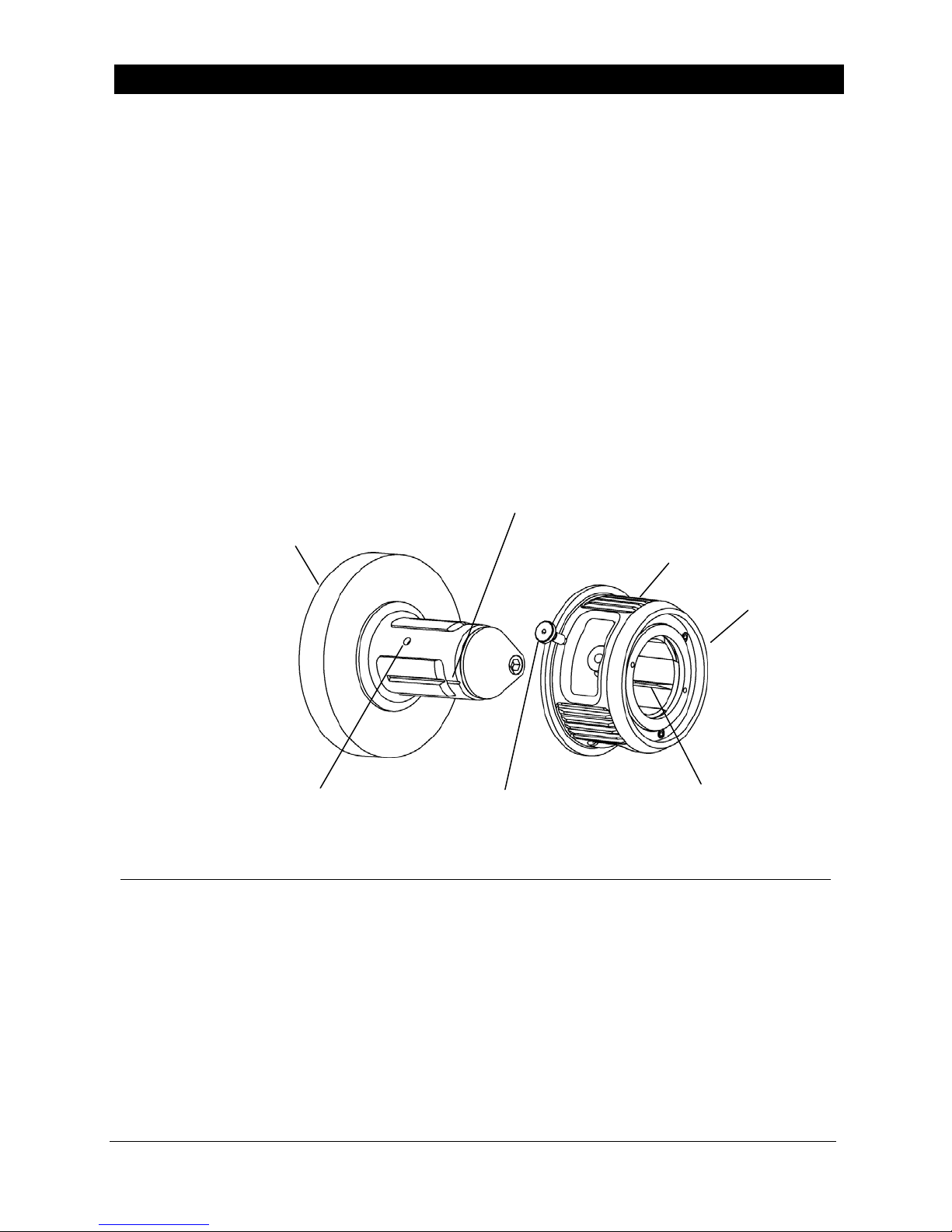
• The locking pin keeps the adapter from sliding off the chuck: It does not transfer torque.
Torque is transferred from chuck to adapter through lug keys on underside of adapter lugs.
• The 3"–5" adapter uses a setscrew instead of a locking pin.
1. Ensure that chuck lugs are completely retracted.
2. Align center of any adapter lug with center slot on any chuck lug.
3. Slide the adapter onto the chuck body, using the alignment reference notch on the chuck
body as a guide. There is a corresponding "key" (ridge) on the underside of each adapter
lug that slides into the slot on top of each chuck body lug.
4. When the adapter contacts the back flange of the torque chuck, hand-tighten the locking
pin until the adapter is secure. Adapter is ready for operation.
Note: If the pin does not seat in one of the three locking pin holes, ensure that the adapter
lug keys are properly aligned on the chuck lugs.
LIGNMENT REFERENCE NOTCH
3" TORQUE CHUCK SHOWN
Air Powered Lug Chucks use
the same locking pin mechanism.
LOCKING PIN HOLE
OF (3
LOCKING PIN
or SETSCREW
(1) OF (3)
DAPTER LUGS
LUG KEY
(1) OF (3)
Operation
When properly installed, the Raptor Series Adapter will function like the chuck. Please refer
to your Tidland Operation and Maintenance Manual for Raptor Series Chuck operation
instructions.
• P/N 660289 Tidland Raptor Series Torque Chuck Manual (3", 4" and 6" chucks)
• P/N 660290 Tidland Raptor Series Air Powered Lug Chuck Manual (3" and 6" chucks)
DAPTER BODY
Tidland Raptor Series Chuck Adapters 643236 1-800-426-1000
Installation, Operation and Maintenance
5
05/11 www.tidland.com
Page 6
A
3" ADAPTERS
Maintenance
The adapter must be removed from the chuck for complete maintenance or disassembly to
replace worn lugs or broken o-rings. Adapter configurations vary; yours may or may not have
all features illustrated here, but assembly procedures are similar.
To Remove Adapter from Chuck
1.
Retract lugs completely. If lugs fail to retract, refer to Troubleshooting, page 16.
Loosen the locking pin (or setscrew). It is not necessary to remove it.
2.
3. Slide adapter off chuck.
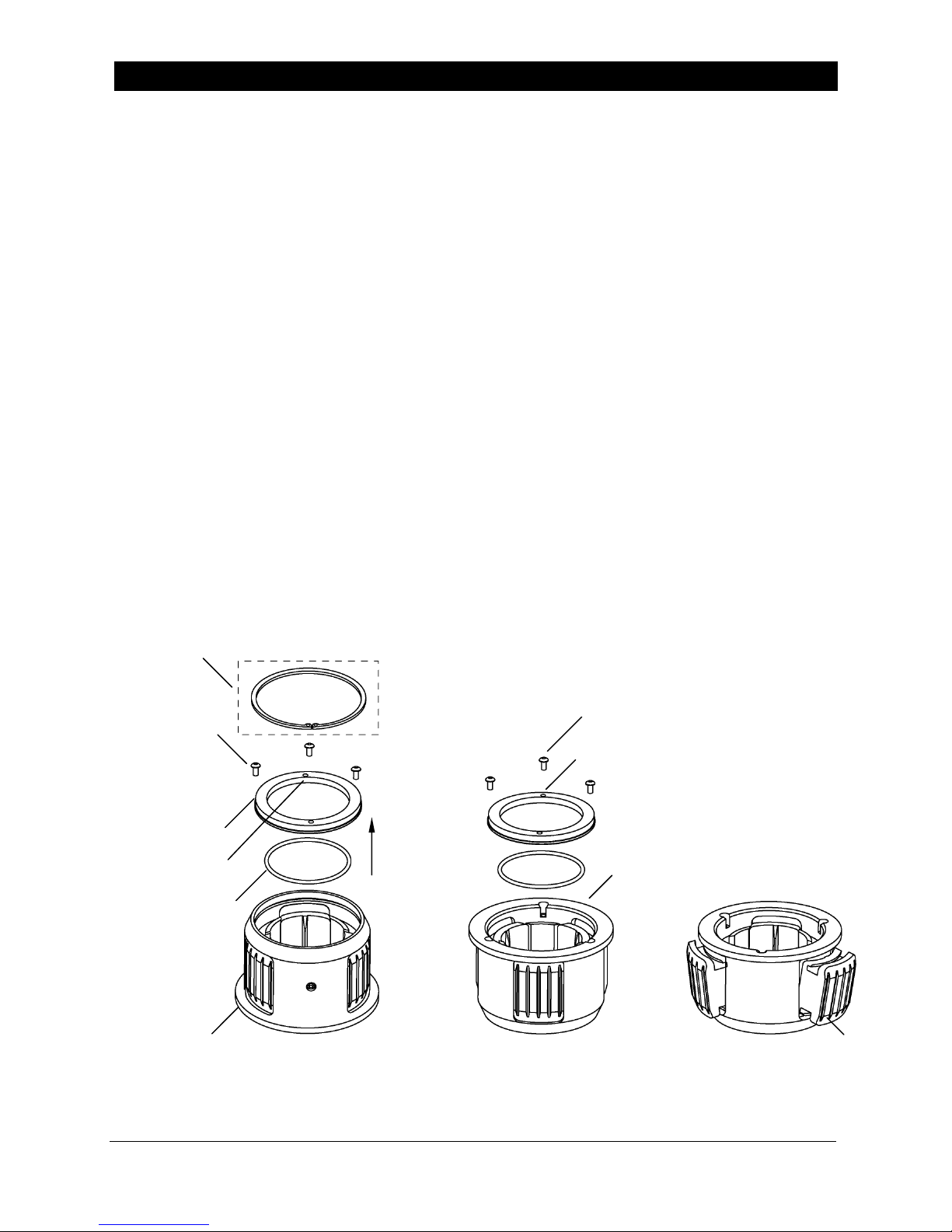
To Disassemble Adapter
1.
Position adapter with flange against the workbench surface.
2. 5" Adapter: Remove the snap ring that holds the lug retainer ring in place.
All other adapter sizes: Remove the bolts that hold the lug retainer ring in place.
3. Remove the retainer ring and o-ring from the lugs.
4. For all four adapter sizes: Turn adapter over and remove the bolts holding the other
retainer ring in place.
5. Remove the retainer ring and o-ring from the lugs. Lugs can now be removed.
6. Remove lugs from slots and inspect for wear.
7. Clean all lug surfaces, lug slots, o-rings, and inside of adapter body. Inspect o-ring for
cracks and replace if necessary.
SNAP RING
5" AD APTER ONLY
BOLTS (3 PLCS)
ALL SIZES EXCEPT 5"
LUG RETAINER RING
JACKING SCREW
THREADS
O-RING
FLANGE
BOLTS (3 PLCS)
LL ADAPTER SIZES
JACKING SCREW
THREADS
FLANGE
STEPS 2, 3 STEP 6
STEPS 4, 5
LUG
Tidland Raptor Series Chuck Adapters 643236 1-800-426-1000
Installation, Operation and Maintenance
6
05/11 www.tidland.com
Page 7
3" ADAPTERS
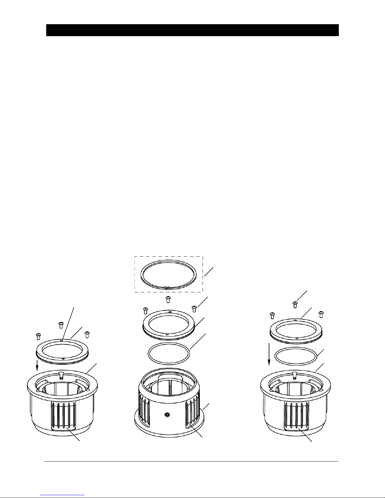
To Reassemble Adapter
Recommended: Clean dust and debris from chuck before reinstalling adapter. See
Operation and Maintenance manual for Tidland Raptor Series Torque Chucks.
• P/N 660289 Tidland Raptor Series Torque Chuck Manual (3", 4" and 6" chucks)
• P/N 660290 Tidland Raptor Series Air Powered Lug Chuck Manual (3" and 6" chucks)
Recommended: Lubricate lug slots and bottom and side surfaces of lugs before
reassembly. Use silicone dry film lubricant. The use of grease products will result in
contamination and allow dirt and dust to accumulate on chuck and adapter parts.
1. Place the adapter body on the work surface with the flange end up.
2. Insert lugs in lug slots and, without the o-ring, temporarily install one lug retainer ring.
Do not use LOCTITE for this step.
Note: Step 2 helps hold the lugs in place while installing the first o-ring in Step 3.
3. Turn the adapter over (flange down) and install the o-ring and retainer ring on the lugs.
4. 5" Adapter: Install snap ring to secure lug retainer ring.
All other adapter sizes: Apply LOCTITE 242 to bolt threads and reinstall bolts using
9 ft·lbs torque (12.2 Nm).
5. Turn the adapter over again; remove the temporarily installed lug retainer ring.
6. Install remaining o-ring and replace the lug retainer ring.
7. All Adapter sizes: Apply LOCTITE 242 to bolt threads and reinstall remaining bolts
using 9 ft·lbs torque (12.2 Nm).
8. Reinstall adapter on chuck, using instructions on page 5.
SNAP RING
5" AD APTER ONLY
BOLTS (3 PLCS)
ALL ADAPTER SIZES
RETAINER RING
O-RING
FLANGE
LUG
JACKING SCREW
THREADS
RETAINER RING
w/o O-RING
FLANGE
LUG
BOLTS (3 PLCS)
ALL SIZES EXCEPT 5"
RETAINER RING
O-RING
FLANGE
LUG
STEP 2 STEPS 3, 4 STEPS 5, 6, 7
Tidland Raptor Series Chuck Adapters 643236 1-800-426-1000
Installation, Operation and Maintenance
7
05/11 www.tidland.com
Page 8
6" ADAPTERS FOR TORQUE CHUCKS
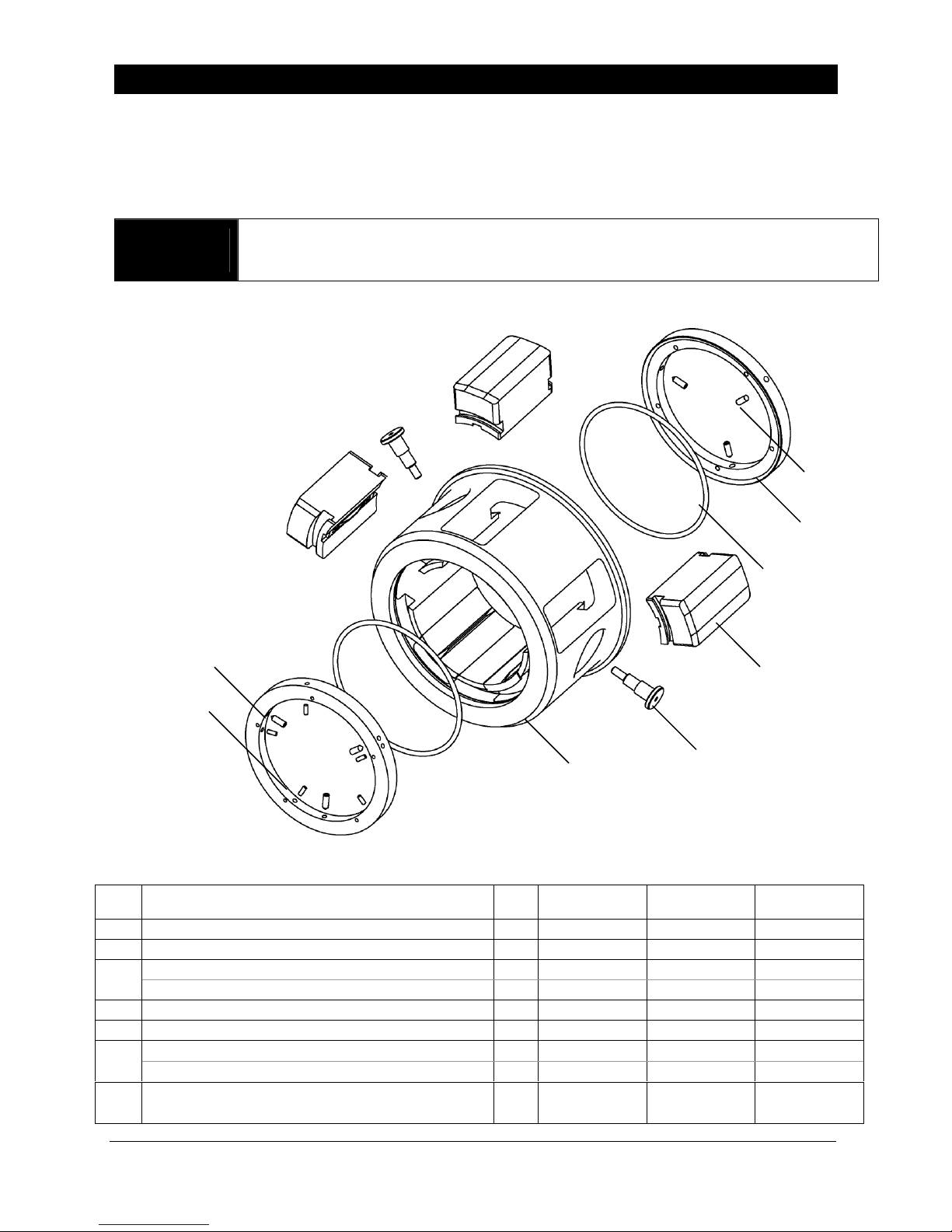
Assembly Diagram and Parts List
These adapters are installed only onto the Tidland 6" Torque Chuck to run core size
applications as listed below (+.010"/+.020"). Adapter installation can be performed without
removing the chuck from the machine.
WARNING
Adapter weights range from 18-74 lbs. Use safe handling procedures. The adapter
is equipped with a 3/8"-16 threaded insert to accommodate a screw eye for lifting.
6"- 8" – Part No. 638413
6"- 10" – Part No. 638414
6"- 12" – Part No. 638415
6
6 *
4
5
2
7
3
1
• LUG APPEARANCE VARIES FOR EACH ADAPTER SIZE.
• THE 10" ADAPTER IS SHOWN HERE.
ITEM DESCRIPTION QTY
1 ADAPTER BODY 1 647037 643775 647034
2 LUG ASSEMBLY 5 647834 645140 648389
LOCKING PIN 2 n/a 643777 647032
3
STSCR 3/8-16UNC x 1" LG HALF DOG PT (GRADE 8) 2 622176 n/a
4 LUG RETAINER RING 2 643776 643776 643776
5 O-RING (PARKER 2-361) 2 659906 659906 659906
STSCR 1/4UNC x .500" LG CONE PT 6 n/a 649727 649727
6
* STSCR 1/4UNC x .500" LG CONE PT 3 649727 n/a
ROLL PIN 3/16" x 13/16" LG
7
TOP RING OF 8" ADAPTER (NO SETSCREWS)
Tidland Raptor Series Chuck Adapters 643236 1-800-426-1000
Installation, Operation and Maintenance
8
5 657956 n/a n/a
8"
PART NO.
05/11 www.tidland.com
10"
PART NO.
n/a
n/a
12"
PART NO.
Page 9
A
A
6" ADAPTERS FOR TORQUE CHUCKS
Installation
• The locking pins keep the adapter from sliding off the chuck – they do not transfer torque.
Torque is transferred from chuck to adapter through lug keys on underside of adapter lugs.
• The 6”-8" adapter uses two setscrews instead of locking pins.
WARNING
Adapter weights range from 18-74 lbs. Use safe handling procedures. The adapter
is equipped with a 3/8"-16 threaded insert to accommodate a screw eye for lifting.
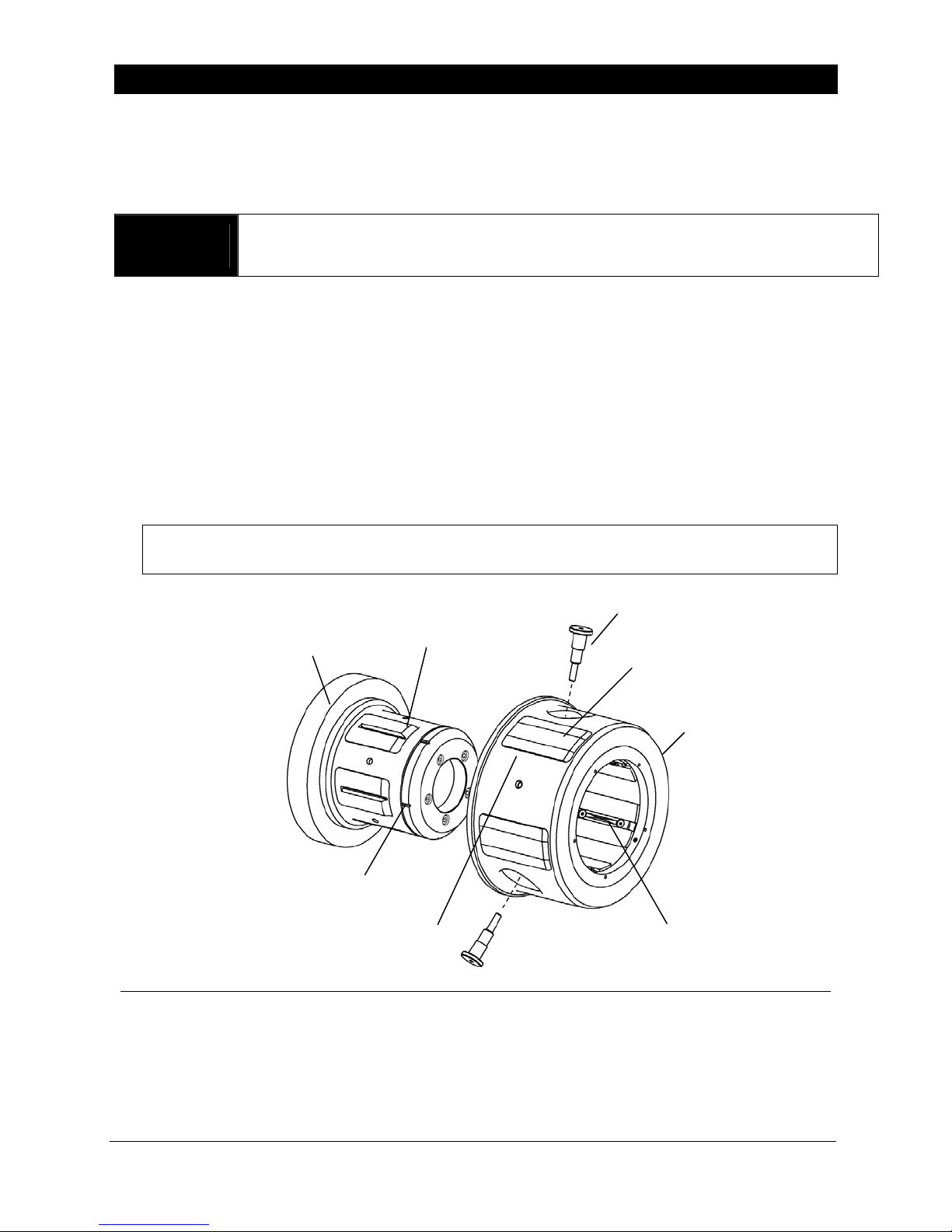
1. Ensure that chuck lugs are completely retracted.
2. Align center of any adapter lug with the center slot on any chuck lug.
3. Slide the adapter onto the chuck body, using the alignment reference notch on the chuck
body as a guide. There is a corresponding "key" (ridge) on the underside of each
adapter lug that slides into the slot on top of each chuck body lug.
4. When the adapter contacts the back flange of the chuck, hand-tighten the two locking
pins until the adapter is secure.
Note: The 6"-8" adapter uses two setscrews instead of locking pins. (3/16 hex drive)
If the locking pins/setscrews do not seat in locking pin holes, ensure that the
adapter lug keys are properly aligned on the chuck lugs.
Do not install the locking pin/setscrews in the threaded insert.
It is not threaded all the way through the adapter body.
LOCKING PIN / SETSCREW
2 PLCS
6" TORQUE CHUCK
LOCKING PIN HOLE
5 PLCS
DAPTER LUGS
5 PLCS
DAPTER BODY
ALIGNMENT REFERENCE NOTCH
5 PLCS
THREADED INSERT
(LIFTING SCREW HOLE)
LUG KEY
5 PLCS
Operation
When properly installed, the Raptor Series Adapter will function like the chuck. Please refer
to your Tidland Operation and Maintenance Manual for Raptor Series Chuck operation
instructions.
• P/N 660289 – Tidland Raptor Series Torque Chuck Manual (3", 4" and 6" chucks)
Tidland Raptor Series Chuck Adapters 643236 1-800-426-1000
Installation, Operation and Maintenance
9
05/11 www.tidland.com
Page 10
6" ADAPTERS FOR TORQUE CHUCKS
Maintenance
The Adapter must be removed from the Torque Chuck for maintenance or for disassembly to
replace worn lugs or broken o-rings.
WARNING
Adapter weights range from 18-74 lbs. Use safe handling procedures. The adapter
is equipped with a 3/8"-16 threaded insert to accommodate a screw eye for lifting.
To Remove Adapter from Chuck
1.
Retract lugs. If lugs fail to retract, refer to Troubleshooting (page 16).
Loosen – do not remove – the locking pins.
2.
3. Slide adapter off chuck and remove to workbench.
To Disassemble Adapter
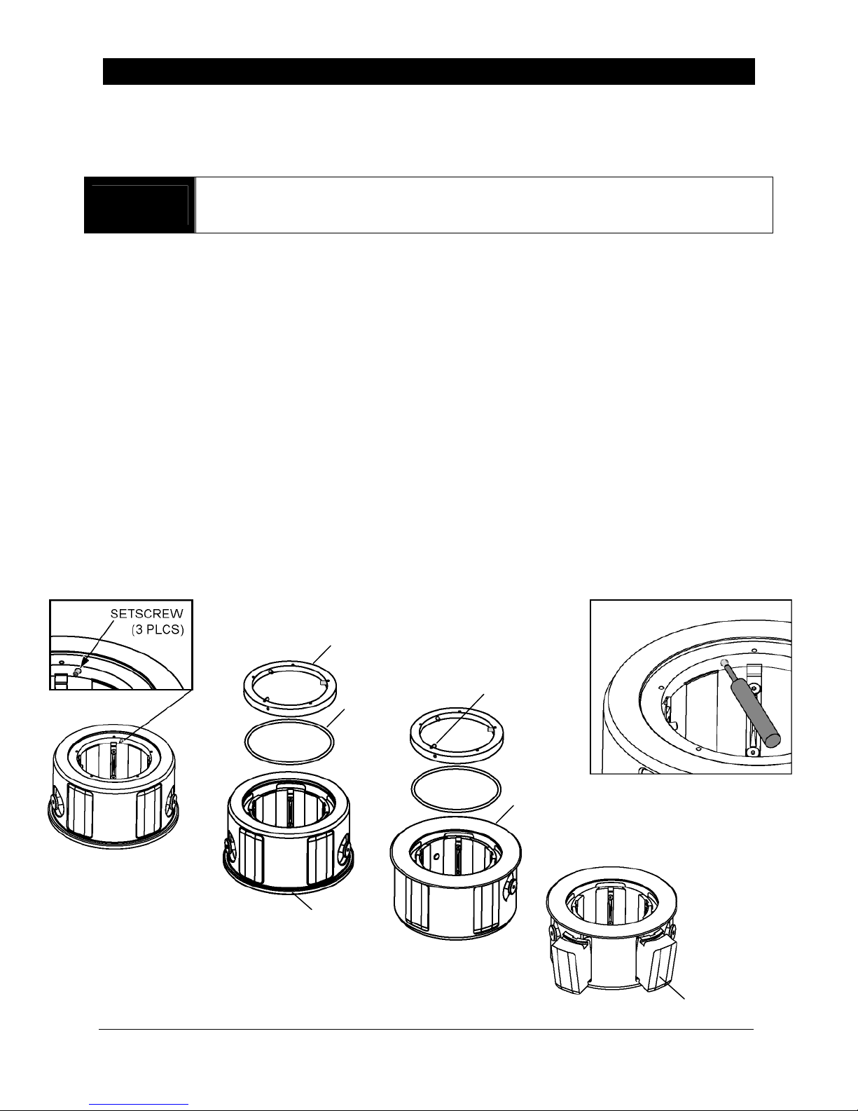
1.
Position adapter with flange against the workbench surface.
2. 6"-10" and 12" Adapters: Using a 1/8" hex drive wrench, loosen – but do not remove –
the three setscrews holding retainer ring in place.
6"-8" Adapters: Use a pin punch to drive out the five roll pins that hold the retainer in
place. To prevent damage to the adapter body, drive pins from the inside out. (Fig. 1)
3. Remove the retainer ring and the o-ring. Lugs are now loose on this end, but still
retained in the body.
4. For all adapter sizes: Turn adapter over and remove the other retainer ring and o-ring.
Lugs can now be removed.
5. Remove lugs from slots and inspect for wear.
6. Clean all lug surfaces, lug slots, o-rings, and inside of adapter body. Inspect o-ring for
cracks and replace if necessary.
Fig. 1
RETAINER RING
SETSCREWS
O-RING
(3 PLCS)
FLANGE
STEP 2
STEP 3
FLANGE
STEP 4
STEP 5
Tidland Raptor Series Chuck Adapters 643236 1-800-426-1000
Installation, Operation and Maintenance
10
05/11 www.tidland.com
LUG
Page 11
A
A
A
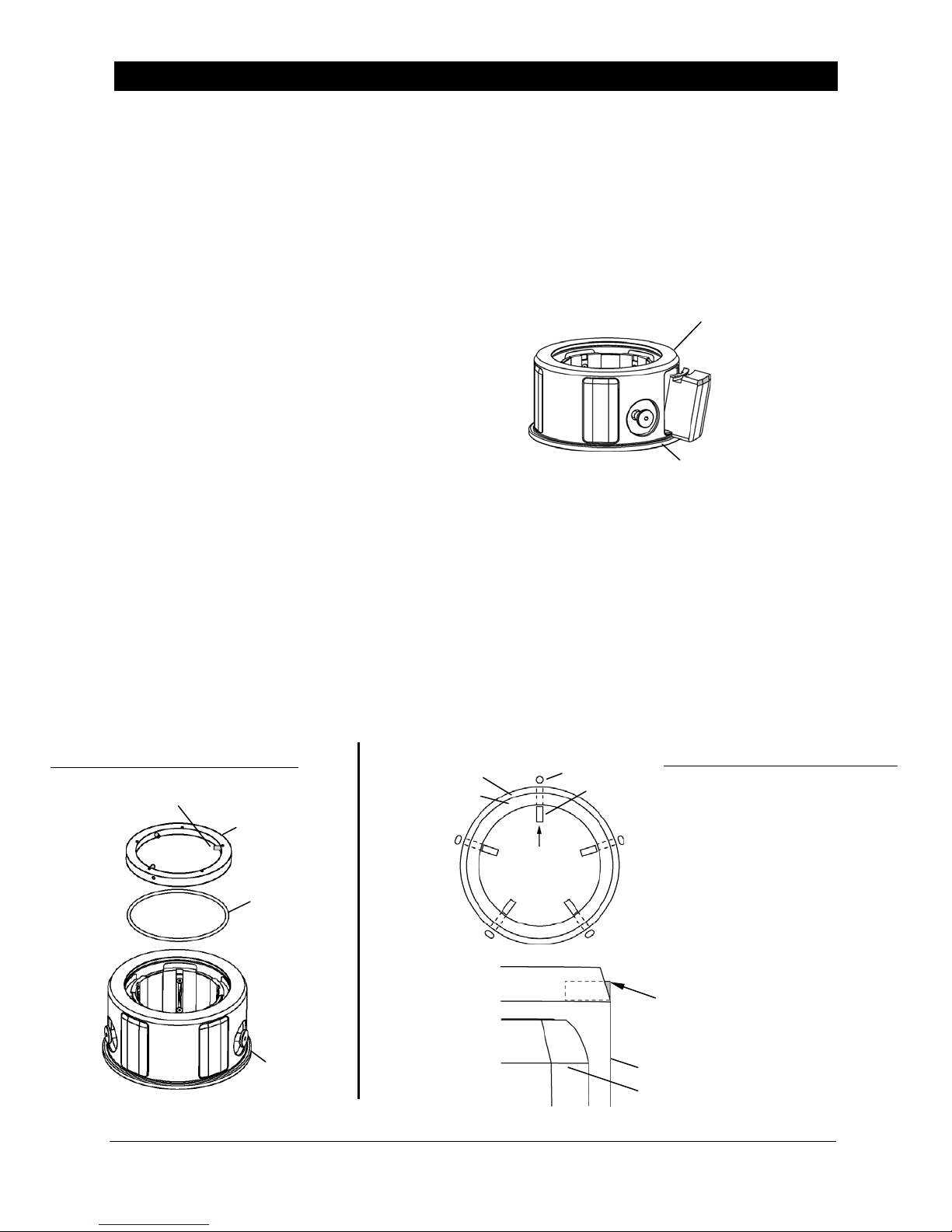
To Reassemble Adapter
Recommended: Clean dust and debris from chuck before reinstalling adapter. See
Operation and Maintenance manual for Tidland Raptor Series Torque Chucks.
• P/N 660289 – Tidland Raptor Series Torque Chuck Manual (3", 4" and 6" chucks)
Recommended: Lubricate lug slots and bottom and side surfaces of lugs before
reassembly. Use silicone dry film lubricant. The use of grease products will result in
contamination and allow dirt and dust to accumulate on chuck and adapter parts.
1. With the adapter flange against the
workbench surface, insert lugs into lug
slots so the outside face of the lug is flush
with the outside face of the adapter body.
2. Reinstall one of the o-rings, making sure that it fits in the grooves of all five lugs.
3. Reinstall one of the retainer rings. Make sure it seats completely over the lugs.
4. For 6"-10" and 12" Adapters: Apply a small amount of LOCTITE 242 to the setscrew
threads and tighten them until they just bottom out. (1/8" hex drive) Do not over tighten.
For 6"-8" Adapter: Use five roll pins, not setscrews. To prevent damage to the adapter
body, drive roll pins through the retainer ring from the inside out. Insert retainer ring and
align holes. Do not drive roll pins through threaded holes.
5. Turn the adapter over and reinstall the remaining o-ring and retainer ring. The flange end
of the adapter uses setscrews on all three sizes: 8", 10", 12".
6. Reinstall adapter on chuck using instructions on page 9.
6"-10", 12" ADAPTER
SETSCREW (3 PLCS)
6" ADAPTERS FOR TORQUE CHUCKS
ADAPTER BODY
RETAINER RING
RETAINER RING
TOP VIEW
O-RING
FLANGE
ROUND HOLE
ROLL PIN
DAPTER NOSE
FLANGE
6"-8" ADAPTER
1. Align retainer ring roll pin
holes with body roll pin holes.
2. Insert first roll pin starting
with the round hole.
3. Insert remaining 4 roll pins in
the oblong holes.
Note:
To prevent damage to the
adapter body, use a pin punch
and drive the roll pins from the
inside out.
ROLL PIN MUST NOT EXTEND
THROUGH TO THE OUTSIDE OF
DAPTER BODY.
DAPTER BODY
LUG
Tidland Raptor Series Chuck Adapters 643236 1-800-426-1000
Installation, Operation and Maintenance
11
05/11 www.tidland.com
Page 12
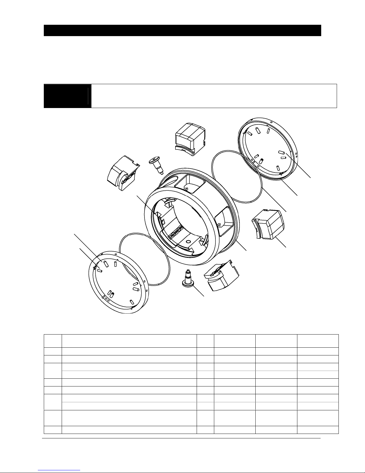
6" ADAPTERS FOR AIR POWERED LUG CHUCKS
Assembly Diagram and Parts List
These adapters are installed only onto the Tidland 6" Air Powered Lug Chuck to run core
size applications as listed below (+.010"/+.020"). Adapter installation can be performed
without removing the chuck from the machine.
WARNING
Adapter weights range from 18-74 lbs. Use safe handling procedures. The adapter
is equipped with a 3/8"-16 threaded insert to accommodate a screw eye for lifting.
6"-8" – Part No. 670787
6"-10" – Part No. 670093
6"-12" – Part No. 670100
8
5
6 *
4
6
7
1
2
3
• LUG APPEARANCE VARIES FOR EACH ADAPTER SIZE.
• THE 10" ADAPTER IS SHOWN HERE.
ITEM DESCRIPTION QTY
1 ADAPTER BODY 1 670788 670094 670101
2 LUG ASSEMBLY 5 670790 670096 670103
LOCKING PIN 2 – 643777 647032
3
STSCR 3/8-16UNC x 1" LG HALF DOG PT (GRADE 8) 2 622176 – –
4 LUG RETAINER RING 2 643776 643776 643776
5 O-RING (PARKER 2-361) 2 659906 659906 659906
STSCR 1/4UNC x .500" LG CONE PT 6 – 649727 649727
6
* STSCR 1/4UNC x .500" LG CONE PT 3 649727 – –
ROLL PIN 3/16" x 13/16" LG
7
FOR TOP RING OF 8" ADAPTER (NO SETSCREWS)
8 ALIGNMENT PIN 1 670098 670098 670098
5 657956 – –
8"
PART NO.
10"
PART NO.
12"
PART NO.
Tidland Raptor Series Chuck Adapters 643236 1-800-426-1000
Installation, Operation and Maintenance
12
05/11 www.tidland.com
Page 13
A
A
6" ADAPTERS FOR AIR POWERED LUG CHUCKS
Installation
• The locking pins keep the adapter from sliding off the chuck – they do not transfer torque.
Torque is transferred from chuck to adapter through lug keys on underside of adapter lugs.
• The 6”-8" adapter uses two setscrews instead of locking pins. (3/16 hex drive)
1. Ensure that chuck lugs are completely retracted.
2. Align center of any adapter lug with the center slot on any chuck lug.
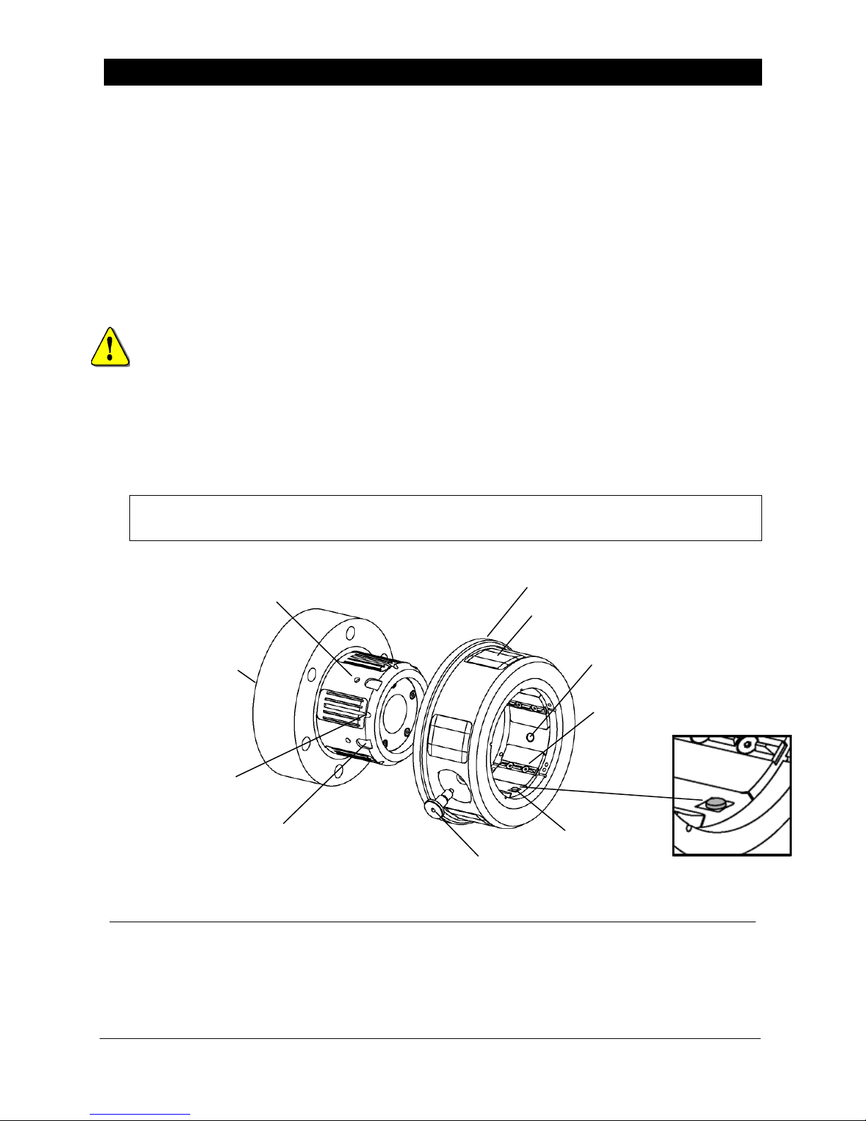
3. Slide the adapter onto the chuck body, using the alignment reference notch on the chuck
body as a guide. There is a corresponding "key" (ridge) on the underside of each
adapter lug that slides into the slot on top of each chuck body lug.
Note the alignment pin on the inside of the adapter. Unless this pin is aligned with
one of the wide slots in the chuck body, you will not be able to slide the adapter all the
way on. If necessary, rotate the adapter slightly on the chuck body until the alignment
pin is in the slot. If the adapter does not contact the back flange, the locking pins will not
engage properly when installed.
4. When the adapter contacts the back flange of the chuck, hand-tighten the two locking
pins until the adapter is secure.
Note: If the locking pins/setscrews do not seat in locking pin holes, ensure that the
adapter is properly aligned on the chuck body. Review Step 3 above.
Do not install the locking pin/setscrews in the threaded insert.
LOCKING PIN HOLE
6" AIR POWERED
LUG CHUCK
ALIGNMENT REFERENCE NOTCH
(ALIGN WITH LUG KEY)
5 PLCS
WIDE ALIGNMENT SLOT
(ALIGN WITH PIN)
Operation
When properly installed, the Raptor Series Adapter will function like the chuck. Please refer
to your Tidland Operation and Maintenance Manual for Raptor Series Chuck operation
instructions.
P/N 660290 – Tidland Raptor Series Air Powered Lug Chuck Manual (3" and 6" chucks)
It is not threaded all the way through the adapter body.
DAPTER BODY
5 PLCS
LOCKING PIN / SETSCREW
2 PLCS
DAPTER LUGS
5 PLCS
ALIGNMENT PIN
THREADED INSERT
(LIFTING SCREW HOLE)
LUG KEY
Tidland Raptor Series Chuck Adapters 643236 1-800-426-1000
Installation, Operation and Maintenance
13
05/11 www.tidland.com
Page 14
6" ADAPTERS FOR AIR POWERED LUG CHUCKS
Maintenance
WARNING
Adapter weights range from 18-74 lbs. Use safe handling procedures. The adapter
is equipped with a 3/8"-16 threaded insert to accommodate a screw eye for lifting.
To Remove Adapter from Chuck
1.
Retract lugs. If lugs fail to retract, refer to Troubleshooting (page 16).
2.
Loosen – do not remove – the locking pins.
3. Slide adapter off chuck and remove to workbench.
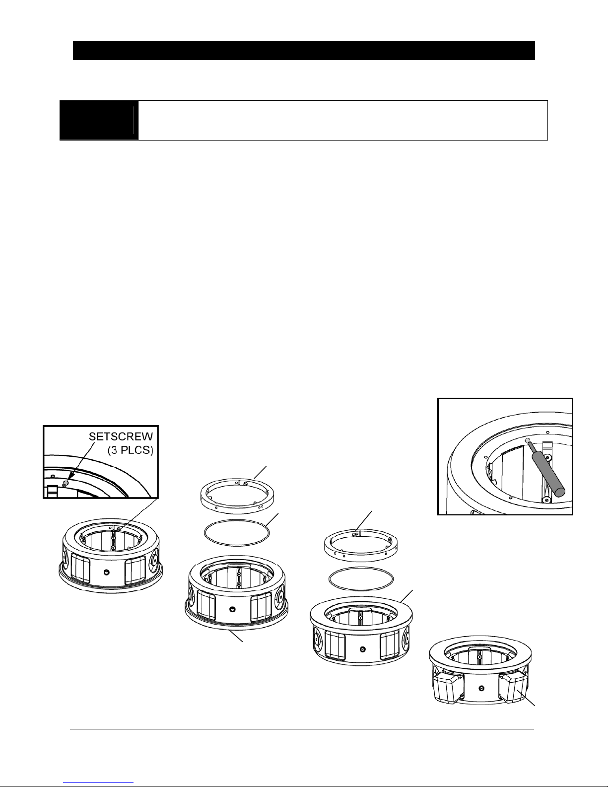
To Disassemble Adapter
1.
Position adapter with flange against the workbench surface.
2. 6"-10" and 12" Adapters: Using a 1/8" hex drive wrench, loosen – but do not remove –
the three setscrews holding retainer ring in place.
6"-8" Adapters: Use a pin punch to drive out the five roll pins that hold the retainer in
place. To prevent damage to the adapter body, drive pins from the inside out. (Fig. 1)
3. Remove the retainer ring and the o-ring. Lugs are now loose on this end, but still
retained in the body.
4. For all adapter sizes: Turn adapter over and remove the other retainer ring and o-ring.
Lugs can now be removed.
5. Remove lugs from slots and inspect for wear.
6. Clean all lug surfaces, lug slots, o-rings, and inside of adapter body. Inspect o-ring for
cracks and replace if necessary.
Fig. 1
RETAINER RING
SETSCREWS
O-RING
(3 PLCS)
FLANGE
STEP 2
STEP 3
FLANGE
STEP 4
STEP 5
Tidland Raptor Series Chuck Adapters 643236 1-800-426-1000
Installation, Operation and Maintenance
14
05/11 www.tidland.com
LUG
Page 15
A
A
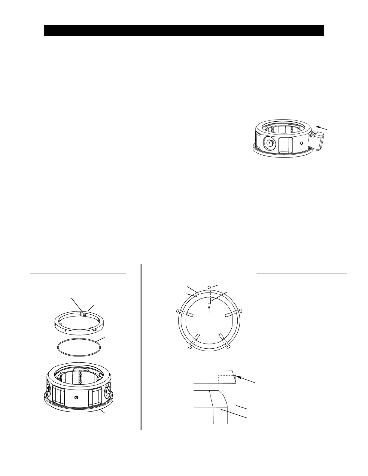
6" ADAPTERS FOR AIR POWERED LUG CHUCKS
To Reassemble Adapter
Recommended:
• Clean dust and debris from chuck before reinstalling adapter. See Operation and
Maintenance manual for Tidland Raptor Series Air Powered Lug Chucks.
• Lubricate lug slots and bottom and side surfaces of lugs before reassembly. Use silicone
dry film lubricant. The use of grease products will result in contamination and allow
dirt and dust to accumulate on chuck and adapter parts.
1. With the adapter flange against the workbench surface, insert
lugs into lug slots so the outside face of the lug is flush with the
outside face of the adapter body.
2. Reinstall one of the o-rings, making sure that it fits in the grooves of all five lugs.
3. Reinstall one of the retainer rings. Make sure it seats completely over the lugs.
4. For 6"-10" and 12" Adapters: Apply a small amount of LOCTITE 242 to the setscrew
threads and tighten them until they just bottom out. (1/8" hex drive) Do not over tighten.
For 6"-8" Adapter: Use five roll pins, not setscrews. To prevent damage to the adapter
body, drive roll pins through the retainer ring from the inside out. Insert retainer ring and
align holes. Do not drive roll pins through threaded holes.
5. Turn the adapter over and reinstall the remaining o-ring and retainer ring. The flange end
of the adapter uses setscrews on all three sizes: 8", 10", and 12".
6. Reinstall adapter on chuck using instructions on page 9.
6"-10", 12" ADAPTER
SETSCREW (3 PLCS)
RETAINER RING
O-RING
FLANGE
ADAPTER BODY
RETAINER RING
TOP VIEW
ROUND HOLE
ROLL PIN
LUG
6"-8" ADAPTER
1. Align retainer ring roll pin
holes with body roll pin holes.
2. Insert first roll pin starting
with the round hole.
3. Insert remaining 4 roll pins in
the oblong holes.
Note:
To prevent damage to the
adapter body, use a pin punch
and drive the roll pins from the
inside out.
ROLL PIN MUST NOT EXTEND
THROUGH TO THE OUTSIDE OF
DAPTER BODY.
DAPTER BODY
Tidland Raptor Series Chuck Adapters 643236 1-800-426-1000
Installation, Operation and Maintenance
15
05/11 www.tidland.com
Page 16

TROUBLESHOOTING RAPTOR SERIES ADAPTERS
Problem Possible Cause Recommended Solution
Adapter lugs don't retract
Adapter moving on chuck
Base chuck lugs still
activated by actuator
Torque Chucks: Rotate chuck backwards
until lugs retract.
Air Powered Chucks: Deflate chuck.
Lugs jammed with core
fibers
Broken rollers or lugs
inside base chuck body
Remove core. Disassemble and clean
adapter lugs.
Remove core. Disassemble and clean
chuck.
Broken o-ring(s) Remove core. Disassemble adapter and
replace broken parts.
Internal core damage
can create buildup of
Remove core. Disassemble and clean
chuck and adapter.
debris between core and
chuck body.
Locking pin/setscrew not
installed
Locking pin/setscrew not
installed correctly
Install locking pin/setscrew.
Check alignment of lug keys and ensure
that locking pin/setscrew is properly
seated.
Locking pin/setscrew
Replace locking pin/setscrew.
broken
Adapter locking pin/
setscrew doesn't seat
Adapter not aligned
properly on chuck
Check alignment of adapter lug keys with
corresponding lugs on chuck. Adapter
should slide on easily when chuck lugs
are fully deflated.
Adapter locking pin/
setscrew breaking off
Core will not fit onto
adapter
Locking pin/setscrew not
fully inserted below
surface of adapter body
Locking pin/setscrew not
fully inserted below
surface of adapter body
Check for proper alignment of locking
pin/setscrew. Ensure that it is fully
inserted and seated in locking pin hole.
Check for proper alignment of locking
pin/setscrew. Ensure that it is fully
inserted and seated in locking pin hole.
Wrong core size Check core size.
All rights reserved. No part of this publication may be reproduced, transmitted, transcribed, stored in a retrieval system,
or translated into any language in any form by any means without the written permission of Tidland Corporation.
Tidland Corporation Maxcess Europe Maxcess Asia
2305 SE 8
Camas, WA 98607 USA Kelkheim/Ts., Germany Orchard Towers
Phone: 1-800-426-1000 Phone: (49) 6195-7002-433 Singapore 238875
1-360-834-2345 Fax: (49) 6195-7002-933 Phone: (65) 9620-3883
Fax: 1-360-834-5865 E-mail: [email protected] Fax: (65) 6235-4818
E-mail: [email protected] E-mail: [email protected]
Web: www.tidland.com
©2011 Maxcess Rights reserved to amend technical details without notice 643236 Rev G May 2011
th
Avenue Fifestrasse 1, D-65779 300 Orchard Road No. 15-05
 Loading...