

Page 1

High Performance Ultrasonic Range Finders
MaxSonar Quick-Start Guide
This is provided to serve as an easy to use set
up guide for the LV‑MaxSonar‑EZ family of
ultrasonic sensors
measure the distance to nearby objects, and
then reports the information through one of
the three sensor outputs
MaxBotix Inc
which is designed to assist you in using your
MaxSonar sensor for the first time
This quick start guide was created using the
LV-MaxSonar-EZ1 MB1010 sensor
., is
.
This sensor uses sound to
.
excited to provide this guide
!
.
-
List of Commonly Used Equipment:
1. Power Supply
2. Multimeter
3. Wires
4. LV‑MaxSonar‑EZ1 (or one of the other MaxSonar products
5. Large flat target
(
218) 454-0766
–
such as a box
)
info@maxbotix.com
MAXBOTIX
(1)
Page 2

Determine the Power and Ground Inputs & Outputs
The following chart is provided as an easy reference guide for connecting our
MaxSonar products
.
Supply Power to the Sensor
1. Disconnect the power supply from any equipment
2. Turn ON the power supply; set the voltage to 5.0V DC (Volts Direct Current
3. Turn OFF the power supply
4. Connect the ground from your power supply to the GND pin on the
.
.
).
LV‑MaxSonar‑EZ1
5. Connect your power supply to +5 pin on the LV‑MaxSonar‑EZ1
6. Turn ON the power supply; verify that the voltage is between +2.5V and +5.5V
The LV‑MaxSonar‑EZ1 input power should be +5V DC. This system can operate from
+2.5V to +5.5V.
.
.
.
The current input should read ~3mA for +5V DC and ~2mA for +3.3V DC
.
(
218) 454-0766
info@maxbotix.com
MAXBOTIX
(2)
Page 3
Connect to the AN Output
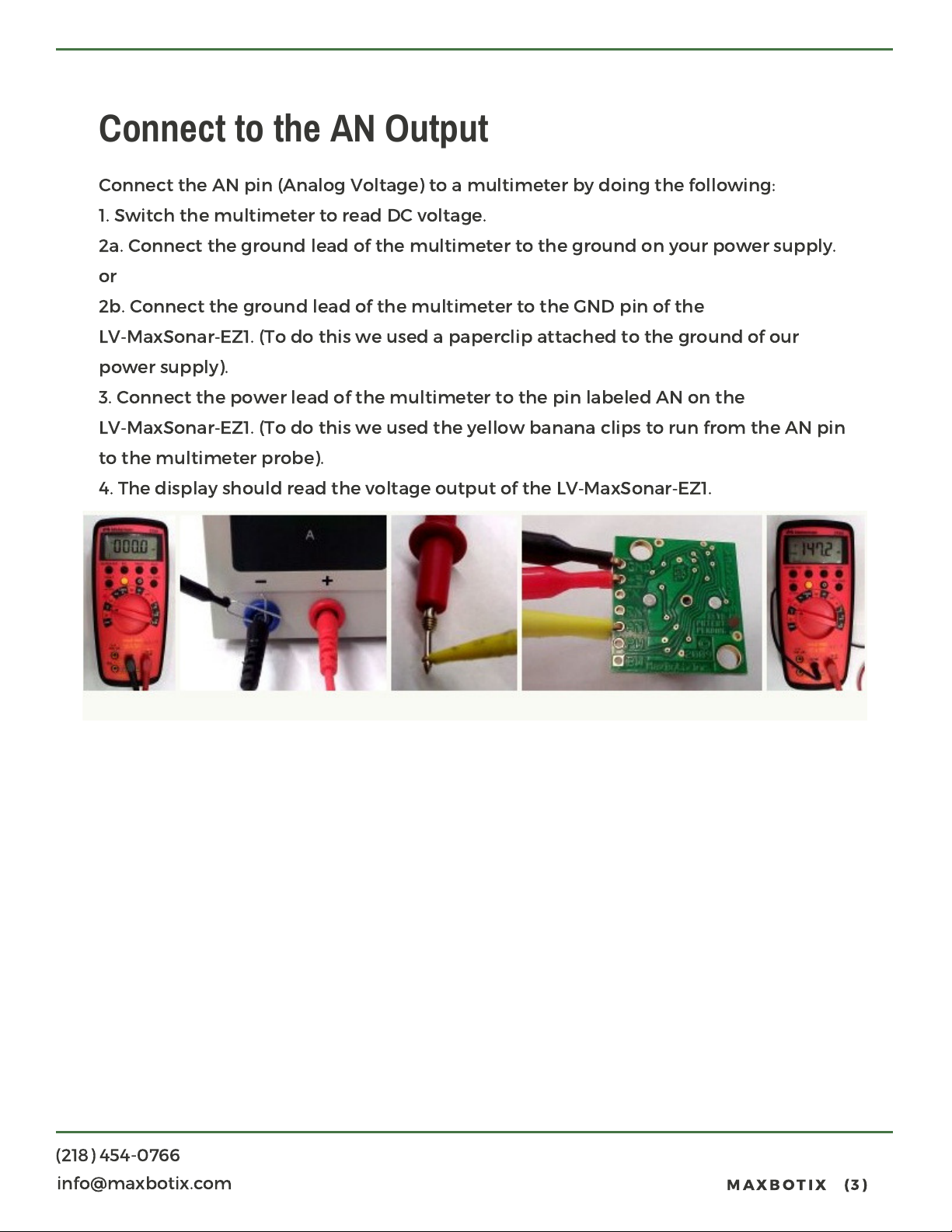
Connect the AN pin (Analog Voltage) to a multimeter by doing the following
1. Switch the multimeter to read DC voltage
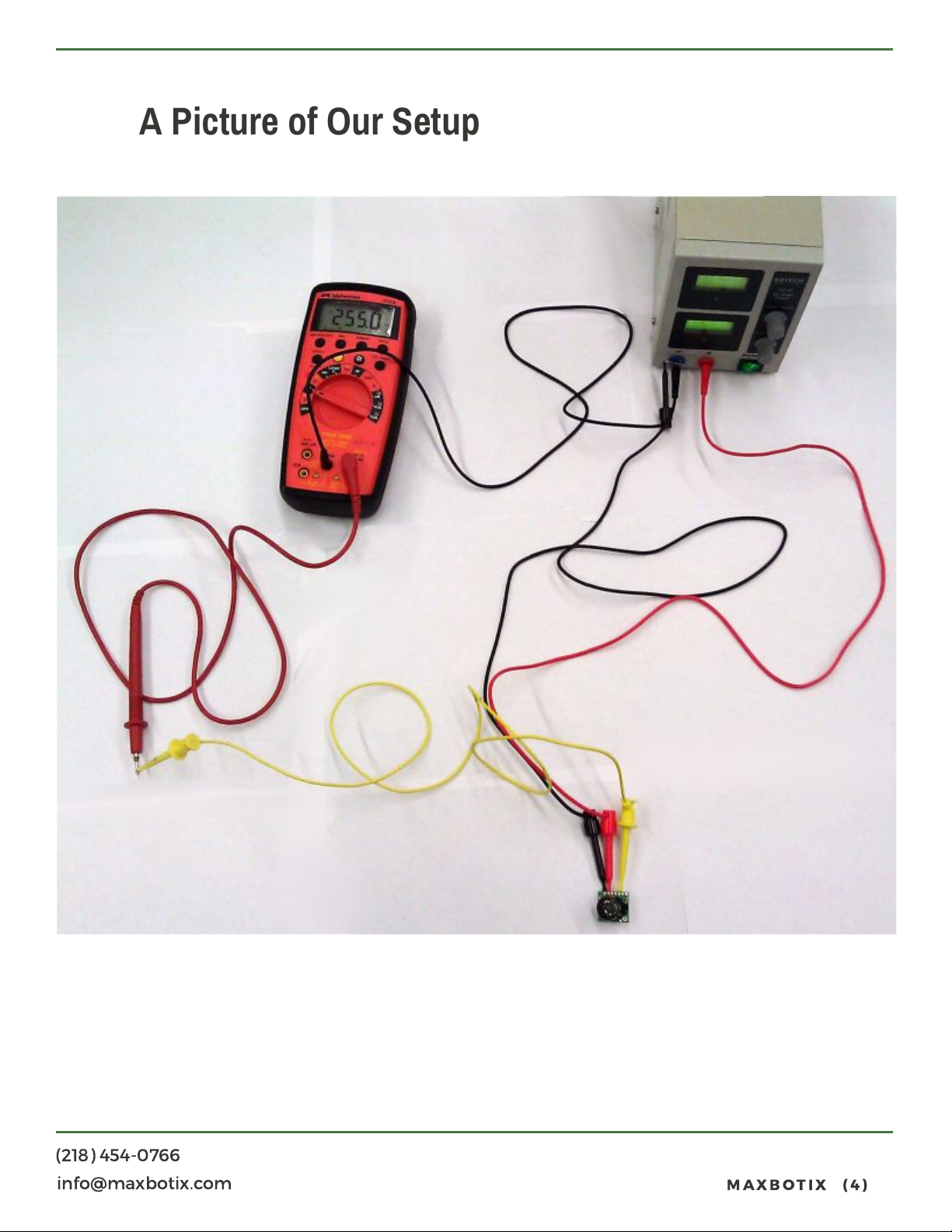
2a. Connect the ground lead of the multimeter to the ground on your power supply
or
2b. Connect the ground lead of the multimeter to the GND pin of the
LV‑MaxSonar‑EZ1
power supply
3. Connect the power lead of the multimeter to the pin labeled AN on the
LV‑MaxSonar‑EZ1
to the multimeter probe
4. The display should read the voltage output of the LV‑MaxSonar‑EZ1
).
. (To do
. (To do
this we used a paperclip attached to the ground of our
this we used the yellow banana clips to run from the AN pin
).
.
.
:
.
(
218) 454-0766
info@maxbotix.com
MAXBOTIX
(3)
Page 4
A Picture of Our Setup
(
218) 454-0766
info@maxbotix.com
MAXBOTIX
(4)
Page 5
Read the AN Output Using a Multimeter
A Brief Description of the AN pin
The analog voltage pin outputs a voltage which corresponds to the distance. The
further away an object is from the sensor the higher the output voltage becomes
which in turn will be measured by the multimeter. The sensor is designed to report
the range to the closest detectable object
.
.
Calculating the Voltage Scaling
Because the LV-MaxSonar-EZ1 output is scaled to the input power that is provided to
the sensor, it is important to know the voltage scaling before calculating the range
The formula for the voltage scaling on an LV‑MaxSonar‑EZ1 is
:
.
[(
Vcc/512
Vcc
Vi
=
Example 1: Say you have an input voltage of +5.0V the formula would read
[(5.0V/
) = Vi]
=
Supplied Voltage
Volts per inch (Scaling
512
) = 0.
009766V per inch
)
= 9.
766mV per inch
]
:
(
218) 454-0766
info@maxbotix.com
MAXBOTIX
(5)
Page 6
Calculating the Range
Once you know the voltage scaling it is easy to properly calculate the range
The range formula is
[(Vm/Vi) = Ri]
Vm
=
Measured Voltage
Vi
=
Volts per Inch (Scaling
Ri
=
Range in inches
Example 2: To get comfortable with this equation use a known distance by using a
ruler. Say the multimeter shows 292.98mV then you use the calculations as follows
[(
292.98mV/9.766mV
Example 3: To work backward and verify your calculation is correct use the inverse
formula
[(Ri x Vi) = Vm] [(30 x 9.
:
:
) = 30
766
)
inches
) =
292.98
]
]
.
:
(
218) 454-0766
info@maxbotix.com
MAXBOTIX
(6)
Page 7
Additional Considerations
Please note that if you are using a sensor from the HR-MaxSonar, XL-MaxSonar-EZ
XL-MaxSonar-AE, XL‑MaxSonar‑WR, or XL‑MaxSonar‑WRC series the voltage scaling
will not match that of the LV‑MaxSonar sensors. To find the voltage scaling of your
sensor reference the product datasheet
Analog Voltage scaling for all of our product lines can be seen in our Using Analog
Voltage (Pin 3) tutorial. This tutorial also includes examples for using the Analog
Voltage output, as well as integrating with a 10‑bit Analog Digital Converter
Please note the sensor resolution, for the LV-MaxSonar-EZ1 the resolution is one inch
The LV-MaxSonar-EZ will, in general, range objects from 0 to 6 inches as 6 inches
Which corresponds to 58.6mV when powered at +5V DC
The LV-MaxSonar-EZ provides range for objects up to 254 inches away. Sensor will
.
.
.
,
.
.
report the closest detectable reflection from an object as defined by the sensor
beam pattern. You may view the beam pattern for the LV-MaxSonar-EZ here
.
(
218) 454-0766
info@maxbotix.com
MAXBOTIX
(7)
Page 8
Connect the LV-MaxSonar-EZ to a Microcontroller
1. It is recommended that you first connect the LV-MaxSonar-EZ to either an
oscilloscope or a multimeter before you connect the LV-MaxSonar-EZ to a
microcontroller for the first time
2. Connect the microcontroller input pin to the desired LV-MaxSonar-EZ sensor
output pin
3. For the AN pin, the following code example is provided for reference: BasicX Code
Example
.
.
Read the AN pin (Analog Voltage) with a Microcontroller
1. Ensure proper microcontroller voltage scaling
2. Ensure proper voltage scaling of the LV-MaxSonar-EZ
3. Use the proper formula for calculating the distance from the voltage that is read
Reference the sensor datasheet
.
.
.
.
Please note: If you are using a microcontroller to read the AN output there is a strong
possibility that the microcontroller has internal voltage scaling
(
218) 454-0766
.
info@maxbotix.com
MAXBOTIX
(8)
 Loading...