

Page 1
TITOLO
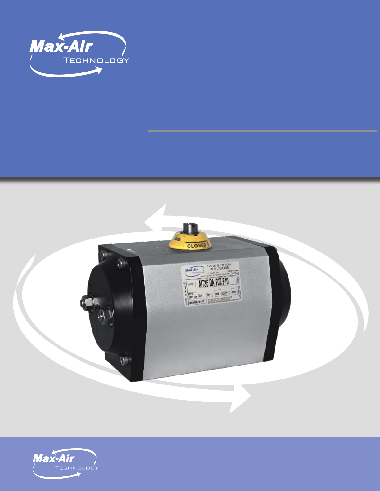
MT SERIES ACTUATORS
Aluminum rack and pinion
pneumatic actuators
Max-Air Technology, Inc. 751 Hoff Rd O’Fallon, Missouri 63366
Tel: +1.636.272.4934 Toll Free: 888.842.9998 Fax: 636.272.4937
www.maxairtech.com E-mail: info@maxairtech.com
1
Page 2
FEATURES & BENEFITS
COMPACT DESIGN
The MAX-AIR rack & pinion pneumatic actuator produces
linear torque output in a compact design utilizing the same
body and end caps for double-acting and spring-return
units.
NAMUR MOUNTING
Namur VDI/VDE 3845 and ISO 5211 dimensions on all
sizes. No special blocks are required to mount solenoid
valves, limit switches or positioners.
DEGREE OF TRAVEL
The standard angle of rotation is 90°. Additional travel
rotations through 180° are available. For sizes from MT08
through MT66, Max-Air actuators feature dual travel stops
that provide ± 10° stroke rotation on both the opening and
closing phases of the actuator stroke. 110° of travel in a
standard 90° actuator!
MULTIPLE OUTPUT SHAFTS
The female pinion drive is standard with a double-square
output drive, and optional with a double-D drive, keyed
drive and designs to meet your specific requirements.
HIGH-CYCLE BEARINGS
Shaft bearings isolate the pinion gear from the housing
and support the shaft for high-cycle applications. Many
competitive manufacturers do not provide this critical
feature.
RUGGED TOOTH DESIGN
The pinion teeth are engaged the full length and stroke of
the piston. The pinion height allows manual override without
needing to remove the indicator.
HIGH VISIBILITY POSITION INDICATION
External open/close indicator as standard, available for all
rotations.
HIGH CYCLE-LIFE WEAR PADS
Pistons incorporate double wear pads (skates) to separate
the rack from the actuator wall and serve as both guide and
wear bearings.
SAFE PRE-LOADED SPRING CARTRIDGES
Epoxy-coated special steel springs are pre-loaded with nonmetallic materials. The stainless steel end-cap fasteners
are extra long to allow for spring relaxation. All parts are
corrosion-resistant.
ALTERNATIVE OPERATING MEDIA
Air pressure operation from 2.8 to 10 Bar (40 to 150 PSI).
Water, nitrogen and compatible hydraulic fluids may also be
used to power the actuator.
STAINLESS STEEL FASTENERS
All external fasteners are corrosion-resistant stainless steel.
HONED BORE FOR HIGH CYCLE-LIFE
Extruded aluminum body is internally machined and honed
to exact specifications. Honing prevents dry spots from
forming within the actuator bore and therefore eliminates
premature seal failure —a critical aspect to long cycle-life.
All internal and external surfaces are hard anodized for
corrosion resistance, with all units permanently lubricated
at the factory.
TRACEABILITY
All units are externally marked with a progressive traceable
serial number.
QUALITY ASSURANCE
100% of all units are factory pressure and leak tested, and
individually boxed for shipment.
BEST WARRANTY IN THE INDUSTRY
Max-Air products are covered by our unlimited cycle-life
warranty. Contact your representative for more details.
ACCESSORIES
Max-Air offers a wide range of adapters for many different
types of valves—including butterfly valves, ball valves and
plug valves—as well as a variety of pneumatic and electric
automation accessories suitable for diverse industrial
environments.
Please call for details.
Introducing Lock Mesh™
Max-Air Technology’s high performance Teon ® infused stainless
steel mesh coating, introduced as our “Lock Mesh™” coating
combines the strength and corrosion resistance of stainless
steel with the technological advancements of infused PTFE.
2
Page 3
DOUBLE ACTING TORQUES
40 PSIG 60 PSIG 80 PSIG 100 PSIG 120 PSIG
MT04
MT12
MT08
MT16
MT17
MT21
MT26
MT31
MT36
MT41
MT46
MT51
MT56
MT61
MT66
MT71
MT76
*All torques in inch pounds (in-lbs)
40 60 80 100 120
62 94 125 156 187
110 147 207 259 295
137 206 275 344 412
180 270 360 450 540
250 375 500 625 750
375 562 750 937 1125
500 750 1000 1250 1500
800 1200 1600 2000 2400
1000 1500 2000 2500 3000
1562 2344 3125 3906 4687
2250 3375 4500 5625 6750
3000 4500 6000 7500 9000
4550 6825 9100 11375 13650
6000 9000 12000 15000 18000
11750 17625 23500 29375 35250
15750 23625 31500 39375 47250
START TO
OPEN
START TO
CLOSE
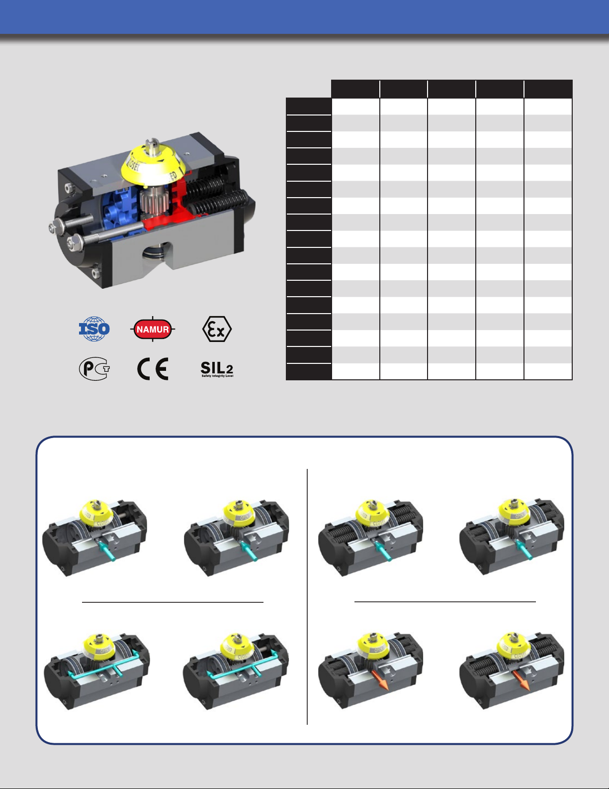
OPERATION REFERENCE DIAGRAM
SPRING RETURNDOUBLE ACTING
OPENING PHASE
AIR IN #4 = PISTONS OPEN
CLOSING PHASE
OPEN
CLOSED START TO
START TO
OPEN
AIR IN #4 = PISTONS OPEN (SPRINGS COMPRESS)
CLOSE
OPENING PHASE
CLOSING PHASE
OPEN
CLOSED
AIR IN #2 = PISTONS CLOSED
Double Acting Operation is also known as “Air to Open, Air to Close” or “Air to Air”.
3
AIR FAILURE = PISTONS CLOSE (SPRINGS RELAX)
Page 4

SPRING RETURN TORQUES MT12-MT41
POS.1
CLOSING TORQUE
POS. 2 OPENING TORQUE
(SPRING) 40 PSIG 60 PSIG 80 PSIG 100 PSIG 120 PSIG
#Springs Start End Start End Start End Start End Start End Start End
1+1 33 22 40 29 72 61 103 92 134 123 165 154
2+2 66 44 – – 50 28 81 59 112 90 143 121
MT12
3+3 99 66 – – – – 58 27 90 66 121 88
1+1 33 20 90 78 127 115 187 175 239 227 275 263
2+2 65 40 70 45 107 82 167 142 219 194 255 230
3+3 98 60 50 13 87 50 147 110 199 162 235 198
MT08
4+4 130 80 – – 67 17 127 77 179 129 215 165
5+5 163 100 – – – – 107 45 159 97 195 133
2+2 75 53 84 62 153 131 222 200 291 269 359 337
3+3 11 2 81 56 25 125 94 194 163 263 232 331 300
4+4 150 107 – – 99 56 168 125 237 194 305 262
MT16
5+5 187 134 – – 72 19 141 88 210 157 278 225
7+5 224 160 – – – – 115 51 184 120 252 188
2+2 93 64 11 6 87 206 177 296 267 386 357 476 447
3+3 139 96 84 41 174 131 264 221 354 3 11 444 401
4+4 185 128 – – 142 85 232 175 322 265 412 355
MT17
5+5 232 160 – – 110 38 200 128 290 218 380 308
7+5 278 192 – – – – 168 82 258 172 348 262
2+2 122 92 158 128 283 253 408 378 533 503 658 628
3+3 184 138 11 2 66 237 191 362 316 487 441 612 566
4+4 245 184 66 5 191 130 316 255 441 380 566 505
MT21
5+5 307 230 – – 145 68 270 193 395 318 520 443
7+5 369 278 – – 97 6 222 131 347 256 472 381
2+2 196 124 251 179 438 366 626 554 813 741 1001 929
3+3 294 185 190 81 377 268 565 456 752 643 940 831
4+4 392 247 – – 315 170 503 358 690 545 878 733
MT26
5+5 490 309 – – 253 72 441 260 628 447 816 635
7+5 588 372 – – – – 378 162 565 349 753 537
2+2 251 187 313 249 563 499 813 749 1063 999 1313 1249
3+3 376 280 220 124 470 374 720 624 970 874 1220 1124
4+4 502 374 – – 376 248 626 498 876 748 1126 998
MT31
5+5 627 467 – – 283 123 533 373 783 623 1033 873
7+5 753 560 – – – – 440 247 690 497 940 747
2+2 412 306 494 388 894 788 1294 1188 1694 1588 2094 1988
3+3 617 461 339 183 739 583 1139 983 1539 1383 1939 1783
4+4 824 614 – – 586 376 986 776 1396 1176 1786 1576
MT36
5+5 1029 767 – – 433 171 833 571 1233 971 1633 1371
7+5 1236 921 – – – – 679 364 1079 764 1479 1164
2+2 505 371 629 495 1129 995 1629 1495 2129 1995 2629 2495
3+3 757 566 444 243 944 743 1444 1243 1944 1743 2444 2243
4+4 1011 741 – – 759 289 1259 989 1759 1489 2259 1989
MT41
5+5 1263 929 – – 572 237 1072 737 1572 1237 2072 1737
7+5 1516 1113 – – – – 887 484 1387 984 1887 1484
*All torques in inch pounds (in-lbs). Spring Return Actuators are also known as “Air to Open, Spring to Close” or “Air to Spring”.
*Actuator drawings may be downloaded at www.maxairtech.com
4
Page 5

SPRING RETURN TORQUES MT46-MT76
POS.1
CLOSING TORQUE
POS. 2 OPENING TORQUE
(SPRING) 40 PSIG 60 PSIG 80 PSIG 100 PSIG 120 PSIG
#Springs Start End Start End Start End Start End Start End Start End
2+2 890 560 1002 672 1784 1454 2565 2235 3346 3016 4127 3797
3+3 1334 840 722 228 1504 1010 2285 1791 3066 2572 3847 3353
4+4 1779 1120 – – 1224 565 2005 1346 2786 2127 3567 2908
MT46
5+5 2224 1399 – – 945 120 1726 901 2507 1682 3288 2463
7+5 2669 1679 – – – – 1446 456 2227 1237 3008 2018
2+2 1101 869 1381 1149 2506 2274 3631 3399 4756 4524 5881 5649
3+3 1652 1304 946 598 2071 1723 3196 2848 4321 3973 5446 5098
4+4 2203 1738 512 47 1637 1172 2762 2297 3887 3422 5012 4547
MT51
5+5 2754 2173 – – 1202 621 2327 1749 3452 2871 4577 3996
7+5 3303 2607 – – 768 72 1893 1197 3018 2322 4143 3447
2+2 1487 1055 1945 1513 3445 3013 4945 4513 6445 6013 7945 7513
3+3 2231 1583 1417 769 2917 2269 4417 3769 5917 5269 7417 6769
4+4 2974 2111 889 26 2389 1526 3889 3026 5389 4526 6889 6026
MT56
5+5 3718 2638 – – 1862 782 3362 2282 4862 3782 6362 5282
7+5 4462 3166 – – 1334 38 2834 1538 4334 3038 5834 4538
2+2 2146 1711 2839 2404 5114 4679 7389 6954 9664 9229 11939 11504
3+3 3220 2566 1984 1330 4259 3605 6534 5880 8809 8155 11084 10430
4+4 4293 3422 1128 257 3403 2532 5678 4807 7953 7082 10228 9657
MT61
5+5 5366 4277 – – 2548 1459 4823 3734 7098 6009 9373 8284
7+5 6438 5133 – – 1692 387 3967 2662 6242 4937 8517 7212
2+2 2810 2084 3916 3190 6916 6190 9916 9190 12916 12190 15916 15190
3+3 4215 3126 2874 1785 5874 4785 8874 7785 11874 10785 14874 13785
4+4 5619 4269 1831 381 4831 3381 7831 6381 10831 9381 13831 12381
MT66
5+5 7024 5211 – – 3789 1976 6789 4976 9789 7976 12789 10976
7+5 8430 6252 – – – – 5748 3570 8748 6570 11748 9570
1+1 2123 1534 10216 9627 16091 15502 21966 21377 27841 27252 33716 33127
2+2 4247 3068 8682 7503 14557 13378 20432 19253 26307 25128 32182 31003
3+3 6370 4602 7148 5380 13023 11255 18898 17130 27773 23005 30648 28880
4+4 8493 6136 5614 3257 11489 9132 17364 15007 23239 20882 29114 26757
5+5 10617 7670 – – 9955 7008 15830 12883 21705 18758 27580 24633
MT71
6+6 12740 9204 – – 8421 4885 14296 10760 20171 16635 26046 22510
7+7 14863 10737 – – – – 12763 8637 18638 14512 24513 20387
8+8 16987 12271 – – – – 11229 6513 17104 12388 22979 18263
1+1 2843 1784 13966 12907 21841 20782 29716 28657 37591 36532 45466 44407
2+2 5686 3569 12181 10064 20056 17939 27931 25814 35806 33689 43681 41564
3+3 8530 5353 10397 7220 18272 15095 26147 22970 34022 30845 41897 38720
4+4 11373 7137 8613 4377 16488 12252 24363 20127 32238 28002 40113 35877
5+5 14216 8922 – – 14703 9409 22578 17284 30453 25159 38328 33034
MT76
6+6 17059 10706 – – 12919 6566 20794 14441 28669 22316 36544 30191
7+7 19902 12490 – – – – 19010 11598 26885 19473 34760 27348
8+8 22746 14275 – – – – 17225 8754 25100 16629 32975 24504
*All torques in inch pounds (in-lbs)
*Actuator drawings may be downloaded at www.maxairtech.com
5
Page 6

HOW TO ORDER
A
A - SPECIAL COATING
ENP = Electroless
Nickel Plated
LMC = LockMesh
Coated
EPOXY = Epoxy
Coated
Omit if N/A
*Note: 1) Not all combinations available, and special
solutions not shown are possible. Please call factory for
details. 2) Max-Air Technology reserves the right to change
or modify products without prior notice & without incurring
any obligation to make such changes on products previously
or subsequently sold.
Important: It is imperative that the air supply pressure
is properly veried when sizing actuators, and to ensure
all supply lines are properly sized to deliver adequate
volume to the actuator, for proper operation.
.
B
B - SPECIAL PINION
DD = Double-D
KYWY = Keyway
Omit if N/A
.
C = SERIES
MT
C D
SAMPLE PART NUMBERS
D = SIZE
04
12
08
16
17
21
26
31
36
41
46
51
56
61
66
71
76
.
E
E - CONFIGURATION
DA = Double-Acting
S2 = 2+2 Springs
S3 = 3+3 Springs
S4 = 4+4 Springs
S5 = 5+5 Springs
S7x5 = 7+5 Springs
F - MOUNTING
F04
F03-F05
F04-F07
F05-F07
F07-F10
F10-F12
F10-F14
F16
(UT SERIES ONLY)
F04/3.25
F12/3.25
5.00/3.25
.
F
.
G - OUTPUT DRIVE
CH11 = 11mm DSQ
CH14 = 14mm DSQ
CH17 = 17mm DSQ
CH22 = 22mm DSQ
CH27 = 27mm DSQ
CH36 = 36mm DSQ
CH46 = 46mm DSQ
.500x.375
.560x.375
.625x.438
.750x.500
.875x.625
1.181x.866
18x10mm
14x22mm
22x14mm
25x19mm
Call for keyway
Other options available
G
H - SPECIAL SEALS
SLT = Super Low Temp
LT = Low Temp
Standard Temp (Omit)
HT = Elevated Temp
.
H
MT26.S4.F05-F07.CH17
SIZE = 26
CONFIGURATION = 4+4 Springs
MOUNTING = F05-F07
OUTPUT DRIVE = 17mm DSQ
ACTUATOR REFERENCE TABLE
Drive (mm) Drive (in) Standard ISO Pattern Optional ISO Pattern
MT04
MT12
MT08
MT16
MT17
MT21
MT26
MT31
MT36
MT41
MT46
MT51
MT56
MT61
MT66
MT71
MT76
9 0.354 F03 -
11 0.433 F04 F03/F05
11 0.433 F03/F05 F04
14 0.551 F05/F07 F04/F07
14 0.551 F05/F07 -
17 0.670 F05/F07 -
17 0.670 F05/F07 -
17 0.670 F05/F07 -
22 0.866 F07/F10 -
22 0.866 F07/F10 -
22 0.866 F07/F10 -
27 1.063 F10/F12 -
27 1.063 F10/F12 -
36 1.417 F10/F14 F10/F12
36 1.417 F10/F14 F10/F12
46 1.811 F16 F14
46 1.811 F16 -
EPOXY.MT31.S5.F05-F07.CH17
SPECIAL COATING = EPOXY
SIZE = 31
CONFIGURATION = 5+5 Springs
MOUNTING = F05-F07
OUTPUT DRIVE = 17mm DSQ
6
Page 7

AIR CONSUMPTION / WEIGHTS / WARRANTY
Double Acting Spring Return
Weight (lbs) Air Consumption (cu-in) Weight (lbs) Air Consumption (cu-in)
MT04
MT12
MT08
MT16
MT17
MT21
MT26
MT31
MT36
MT41
MT46
MT51
MT56
MT61
MT66
MT71
MT76
*Note: Spring return weights consider actuator tted with max number of springs possible. Air consumption is normalized at standard temperature and pressure.
1.06 4.03 NA NA
2.00 13.50 2.18 8.00
2.76 15.26 3.00 6.10
3.52 25.60 3.94 11.20
4.22 34.30 4.75 15.60
5.17 44.40 6.00 18.10
7.1 5 68.70 8.30 30.00
9.13 88.90 10.74 40.60
14.60 153.10 17.80 75.00
17.20 190.60 20.90 100.00
24.20 275.00 29.90 115.60
35.30 425.00 42.00 181.30
44.10 565.50 53.80 256.30
61.50 881.30 83.10 343.80
84.50 1037.50 105.60 443.80
147.30 1694.00 182.90 600.00
179.90 1963.00 216.10 731.00
STANDARD WARRANTY INFORMATION
Max-Air Technology provides the following warranty regarding products manufactured by it. THE WARRANTY STATED HEREIN IS EXPRESSELY IN LIEU OF ALL OTHER
WARRANTIES AND REPRESENTATIONS, EXPRESSED OR INPLIED, OR STATUTORY, INCLUDING, WITHOUT LIMITATION, THE IMPLIED WARRANTY OF FITNESS FOR
A PARTICULAR PURPOSE. Max-Air Technology warrants its products to be free from defects in materials and workmanship when these products are used for the purpose for
which they were designed and manufactured. Max-Air Technology does not warrant its products against chemical or stress corrosion or against any other failure other than from
defects in materials or workmanship. The warranty period is for twelve (12) months from installation date or eighteen (18) months from shipment date, whichever date comes
first. Any claims regarding this warranty must be in writing and received by Max-Air Technology before the last effective date of the warranty period. Upon Max-Air Technology
receipt of a warranty claim, Max-Air Technology reserves the right to inspect the product(s) in question at either the field location or at Max-Air Technology Manufacturing plant.
If, after inspection of the product(s) in question, Max-Air Technology determines that the purchaser’s claim is covered by this warranty, Max-Air Technology’s sole liability and the
purchaser’s sole remedy under this warranty is limited to the refunding of the purchase price or repair or replacement thereof a Max-Air Technology option. Max-Air Technology will
not be liable for any repairs, labor, material or other expenses that are not specifically authorized in writing by Max-Air Technology, and in no event shall Max-Air Technology be
liable for any direct or consequential damages arising out of any defect from any cause whatsoever. If any Max-Air Technology product is modified or altered at any location other
than Max-Air Technology – St. Louis (Missouri) or Max-Air Technology – Sesto San Giovanni (Milan) ITALY without the express written authorization of Max-Air Technology are
not covered by this warranty. The warranty for such products shall be subject only to the warranty relief, if any, provided by the suppliers and/or manufacturers of such products.
UNLIMITED CYCLE LIFE WARRANTY
Max-Air Technology, Inc. provides the following unlimited cycle life warranty regarding products manufactured by Max-Air Technology, Inc. of O’Fallon, Missouri and Emme
Technology S.r.l. of Sesto San Giovanni, Italy, a.k.a. the “Max-Air Group”. This warranty includes all aluminum rotary rack and pinion actuators which are manufactured by the
Max-Air Group and brand labeled for marketing purposes for other companies and business entities, and applies only to those items which are clearly identified as Max-Air brand
labeled products. The warranty stated herein is expressly in lieu of all other warranties and representations, expressed or implied, or statutory, including, without limitation, the
implied warranty of fitness for a particular purpose. Max-Air Technology warrants it products to be free from defects in materials and workmanship when these products are
used for the purpose for which they were designed and manufactured. Max-Air Technology does not warrant its products against chemical or stress corrosion or against any
other failure other than from defects in materials or workmanship. The warranty period is for twelve (12) months from installation date or eighteen (18) months from shipment
date, whichever date comes first. Any claims regarding this warranty must be in writing and received by Max-Air Technology before the last effective date of the warranty period.
Upon receipt of a warranty claim, Max-Air Technology reserves the right to inspect the product(s) in question at either the field location or at a Max-Air designated facility. If,
after the inspection of the product(s) in question, Max-Air Technology determines that the purchaser’s claim is covered by this warranty, Max-Air Technology’s sole liability and
the purchaser’s sole remedy under this warranty is limited to the refunding of the purchase price or repair or replacement thereof, at the sole discretion of Max-Air Technology.
Max-Air Technology will not be liable for any repairs, labor, material, or other expenses that are not specifically authorized in writing by Max-Air Technology, and in no event shall
Max-Air Technology be liable for any direct or consequential damages arising out of any defect from any cause whatsoever. If any Max-Air Technology products are modified
or altered in any way, without the expressed written consent of Max-Air Technology, the products will not be covered by this warranty. Max-Air Technology further warrants
its aluminum rotary rack and pinion pneumatic actuator products to be free from seal failure for the life of the product when such product(s) are used for the purpose in which
they are designed. This warranty extension shall be known as the ‘Unlimited Cycle Life Warranty’ and provides that in the event of seal failure outside the standard warranty
time period, Max-Air Technology will inspect and repair the product(s) in question free of charge. If during the inspection, Max-Air Technology, or its authorized service repair
center, finds that failure was caused by the introduction of foreign debris into the internal operating mechanism of the pneumatic actuator, and/or finds that failure was caused
by end user modification, then the warranty extension shall be null and void. The unlimited cycle life warranty does not cover the freight charges to and from an authorized
Max-Air Technology service repair center, regardless if warranty coverage is applicable or not. Warranty coverage provides for replacement of all wear bearing parts, and other
components if necessary as determined by Max-Air Technology or its authorized service repair center. Max-Air Technology reserves the right to end this warranty extension at
anytime at its sole discretion, and without notification.
7
Page 8

MT04 EXPLODED VIEW
Blue = Items sold in the skates and
wear bearings repair kit
Red = Items sold in the o-ring repair kit
18
17
3
6
5
8
14
11
21
1
2
4
IMPORTANT SPECIAL FEATURE!
The MAX-AIR MT04 is designed so that standard NAMUR mount
solenoid valves can be connected horizontally. This is a MAX-AIR
EXCLUSIVE feature.
13
15
16
10
9
7
22
19
5
4
23
3
25
1
24
20
# DESCRIPTION MATERIALS
1 End Cap Bolts AISI 304 Stainless Steel
2 Left End Cap Die Cast Aluminum Epoxy Coated
6 Left Piston Anodized Aluminum
8 Actuator Body Extruded Aluminum (6063 or 6005)
9 Upper Pinion Washer Technopolymer
10 Pinion Snap Ring AISI 304 Stainless Steel
11 Pinion Nickel Plated Carbon Steel
16 Indicator Inserts Technopolymer
17 Indicator Technopolymer
18 Indicator Screw AISI 304 Stainless Steel
19 Right Piston Anodized Aluminum
20 Travel Stop AISI 304 Stainless Steel
21 Travel Stop AISI 304 Stainless Steel
22 Right End Cap Die Cast Aluminum Epoxy Coated
24 Travel Stop Nuts AISI 304 Stainless Steel
NOTE
The MT04 is the smallest actuator in our MT lineup. The MT04 is only
available in double-acting conguration, and Standard Buna Seals.
# DESCRIPTION MATERIALS
4 Piston Wear Bearing Technopolymer
7 Piston Skate Technopolymer
13 Upper Pinion Bearing Technopolymer
# DESCRIPTION MATERIALS
3 End Cap O-Ring BUNA-N
5 Piston O-Ring BUNA-N
14 Upper Pinion O-Ring BUNA-N
15 Lower Pinion O-Ring BUNA-N
23 Travel Stop Washers AISI 304 Stainless Steel
25 Travel Stop O-Rings BUNA-N
8
Page 9

MT04 & MT12 TECHNICAL DATA
.787
.205
.394
.315
.472
2x 1/8" NPT
4x #10-32x.315
.945
(NAMUR)
1.260
(NAMUR)
.157
M6x.470
4x #10-32x.315
.984
1.969
3.94
2.00
1.56
.98
2.75
.783
.43
.02
1.10
Beacon
Indicator
(Removable)
#10-32" UNFx.394
.354
.354
1.417
ISO F03
INCHES
IN
DIMENSIONS
3845
VDI/VDE
NAMUR
AND
3337
DIN-1521
ISO
O
T
DIMENSIONS
TECHNICAL DATA
MT04
M
I
H
A
B
C
D
F
L
MT04
MT12
*Only available in Double Acting conguration, and with Standard Buna-N Seals (-4°F to 176°F).
MT12
A B C D F I L M F05 F03/F04 DSQ ISO 5211
2.64 1.57 0.47 2.80 0.49 0.87 4.69 0.394
#10-32x.394
#10-32x.394 — F04
¼"-20x.394
11 mm
(0.433in)
9
F03/F05
Page 10

MT12 EXPLODED VIEW
Blue = Items sold in the skates and
wear bearings repair kit
Red = Items sold in the o-ring repair kit
18
2
1
5
3
6
7
8
14
11
10
13
12
17
16
9
7
19
5
3
2
1
15
# DESCRIPTION MATERIALS
1 End Cap Bolts AISI 304 Stainless Steel
2 Left End Cap Die Cast Aluminum Epoxy Coated
6 Left Piston Anodized Aluminum
8 Actuator Body Extruded Aluminum (6063 or 6005)
9 Upper Pinion Washer Technopolymer
10 Pinion Snap Ring AISI 304 Stainless Steel
11 Pinion Nickel Plated Carbon Steel
16 Open/Closed Indicator Technopolymer
17 Indicator Window Technopolymer
18 Indicator Snap Ring AISI 304 Stainless Steel
19 Travel Stop Piston Anodized Aluminum
# DESCRIPTION MATERIALS
7 Piston Skate Technopolymer
12 Lower Pinion Bearing Technopolymer
13 Upper Pinion Bearing Technopolymer
# DESCRIPTION MATERIALS
3 End Cap O-Ring BUNA-N
5 Piston O-Ring BUNA-N
14 Upper Pinion O-Ring BUNA-N
15 Lower Pinion O-Ring BUNA-N
SPECIAL NOTE
The second smallest actuator in our lineup, the MT12 actuator is designed without dual travel stop adjustments to save space, while at the same time
offered in both DA (double-acting) and SR (spring-return) congurations. Available only in Standard Buna-N Seals (-4°F to 176°F).
10
Page 11

MT08 - MT66 EXPLODED VIEW
1
2
3
6
Blue = Items sold in the skates and
wear bearings repair kit
18
Red = Items sold in the o-ring repair kit
17
7
4
5
14
8
11
12
15
# DESCRIPTION MATERIALS
1 End Cap Bolts AISI 304 Stainless Steel
2 Left End Cap Die Cast Aluminum Epoxy Coated
6 Left Piston Anodized Aluminum
8 Actuator Body Extruded Aluminum (6063 or 6005)
9 Upper Pinion Washer Technopolymer
10 Pinion Snap Ring AISI 304 Stainless Steel
11 Pinion Nickel Plated Carbon Steel
16 Open/Closed Indicator Technopolymer
17 Indicator Window Technopolymer
18 Indicator Snap Ring AISI 304 Stainless Steel
19 Travel Stop Piston Anodized Aluminum
20 Closed Travel Stop AISI 304 Stainless Steel
21 Open Travel Stop AISI 304 Stainless Steel
22 Travel Stop End Cap Die Cast Aluminum Epoxy Coated
24 Travel Stop Nuts AISI 304 Stainless Steel
16
10
9
19
13
5
4
7
21
22
20
3
1
# DESCRIPTION MATERIALS
4 Piston Wear Bearing Technopolymer
7 Piston Skate Technopolymer
12 Lower Pinion Bearing Technopolymer
13 Upper Pinion Bearing Technopolymer
# DESCRIPTION MATERIALS
3 End Cap O-Ring BUNA-N
5 Piston O-Ring BUNA-N
14 Upper Pinion O-Ring BUNA-N
15 Lower Pinion O-Ring BUNA-N
23 Travel Stop O-Rings BUNA-N
23
24
SERVICE CODE DESCRIPTION
Super Low Temperature SLT
Severe Cold LT
Standard STD
Elevated Temperature HT
For super low temperatures down to -67°F, special super low temperature seals and lubricant must
be used.
For temperatures below -4°F down to -49°F, special low temperature seals and lubricant must be
used.
Actuators come standard with BUNA-N seals, which are good for normal temperature ranges of -4°F
to 176°F.
For elevated temperatures up to 300°F, VITON® seals are available. Typical VITON® installations
are good for 300°F continuous and 350°F cyclic.
11
Page 12

MT08 - MT66 TECHNICAL DATA
1.18
K
E
G
J
F
A
45°
DSQ
B
A
H
90°
0.157 0.157
DETAIL C:
Top Pinion
C
D
I
A
X
W
SECTION A-A:
Valve Connection
ISO 5211 Flange
M
#10-32 x.315
0.56
1/4" NPT
C
B
L
#10-32 x.315
DETAIL B:
SV Connection
1.26
0.95
3.15
1.18
*Double-D and keyway drive options available. Contact Max-Air for details.
A B C D E F G H I L M J K W X DSQ ISO 5211
2.64 1.57 0.47 2.80 1.77 0.49 0.06 1.85 0.87 4.69 0.394
MT12
2.76 1.62 0.47 2.68 1.70 0.65 0.06 2.07 1.02 6.30 0.394
MT08
3.19 1.85 0.47 3.19 1.75 0.75 0.08 2.44 1.30 6.50 0.394
MT16
3.19 1.85 0.47 3.19 1.75 0.75 0.08 2.44 1.30 7.76 0.394 1.97
MT17
3.78 2.13 0.55 3.86 1.77 0.75 0.08 3.01 1.38 6.70 0.394 1.97
MT21
3.78 2.13 0.55 3.86 1.77 0.75 0.08 3.01 1.38 9.41 0.394 1.97
MT26
4.49 2.44 0.77 4.61 1.73 0.91 0.08 3.56 1.59 9.06 0.551 1.97
MT31
5.16 2.60 0.77 6.06 1.77 1.18 0.12 3.76 1.59 9.69 0.551 2.76
MT36
5.16 2.60 0.77 6.06 1.77 1.18 0.12 3.76 1.77 11.42 0.551 2.76
MT41
5.71 2.87 1.10 6.63 1.77 1.18 0.12 3.88 2.22 13.81 0.787 2.76
MT46
7.13 3.58 1.10 7.95 1.73 1.57 0.12 4.33 2.13 14.21 0.787 4.02
MT51
7.13 3.58 1.10 7.95 1.73 1.57 0.12 4.90 2.62 16.46 0.787 4.02
MT56
9.13 4.49 1.10 10.12 1.77 1.97 0.16 6.32 3.15 17.48 0.787 4.02
MT61
9.13 4.49 1.10 10.12 1.77 1.97 0.16 6.32 3.15 19.76 0.787 4.02
MT66
1.42 #10-32x.394 1.969
1.65 #10-32x.394 — — F04
1.42 #10-32x.315 1.969
1.65 #10-32x.315 — — F04
1.97
¼"-20x.394
1.65 #10-32x.394 F04/F07
¼"-20x.394
¼"-20x.512
¼"-20x.512
¼"-20x.512
5
/16"-18x.512
5
/16"-18x.512
5
/16"-18x.512
3
3
3
3
Note*: Dimensions subject to change without notice. Dimensions in inches unless otherwise noted.
/8"-16x.709
/8"-16x.709
/8"-16x.709
/8"-16x.709
2.756
2.756
2.756
2.756
2.756
4.016
4.016
4.016
4.921
4.921
4.921
5.512
4.921
5.512
¼"-20x.394
¼"-20x.394
5
/16"-18x.512
5
/16"-18x.512
5
/16"-18x.512
5
/16"-18x.512
5
/16"-18x.512
3
/8"-16x.709
3
/8"-16x.709
3
/8"-16x.709
½"-13x.787
½"-13x.787
½”-13x.787
5
/8"-11x.984
½”-13x.787
5
/8”-11x.984
Note: Envelope dimensions shown, see individual cutsheets for dimensional details.
11 mm
11 mm
14 mm
14 mm F05/F07
17 mm F05/F07
17 mm F05/F07
17 mm F05/F07
22 mm F07/F10
22 mm F07/F10
22 mm F07/F10
27 mm F10/F12
27 mm F10/F12
36 mm
36 mm
F03/F05
F03/F05
F05/F07
F10/F12
F10/F14
F10/F12
F10/F14
12
Page 13

MT71 - MT76 EXPLODED VIEW
26
23
21
1
2
6
3
27
18
17
16
27
Blue = Items sold in the skates and
wear bearings repair kit
Red = Items sold in the o-ring repair kit
19
5
4
22
1
4
5
8
14
9
11
# DESCRIPTION MATERIALS
1 End Cap Bolts AISI 304 Stainless Steel
2 Left End Cap Die Cast Aluminum Epoxy Coated
6 Left Piston Anodized Aluminum
8 Actuator Body Extruded Aluminum (6063 or 6005)
10 Pinion Snap Ring AISI 304 Stainless Steel
11 Pinion Nickel Plated Carbon Steel
16 Open/Closed Indicator Technopolymer
17 Indicator Window Technopolymer
18 Indicator Snap Ring AISI 304 Stainless Steel
19 Right Piston Anodized Aluminum
20 Travel Stop, Open AISI 304 Stainless Steel
21 Travel Stop, Closed AISI 304 Stainless Steel
22 Right End Cap Die Cast Aluminum Epoxy Coated
26 Travel Stop Nut AISI 304 Stainless Steel
27 Lifting Eyelets Forged Stainless Steel
7
25
15
10
Note*: Now available with bi-directional travel stops, +/-10° Adjustment.
3
23
# DESCRIPTION MATERIALS
4 Piston Wear Bearing Technopolymer
7 Piston Skates Technopolymer
9 Upper Pinion Bearing Technopolymer
25 Lower Pinion Bearing Technopolymer
# DESCRIPTION MATERIALS
3 End Cap O-Ring BUNA-N
5 Piston O-Ring BUNA-N
14 Upper Pinion O-Ring BUNA-N
15 Lower Pinion O-Ring BUNA-N
23 Travel Stop O-Rings BUNA-N
20
26
SERVICE CODE DESCRIPTION
Super Low Temperature SLT
Severe Cold LT
Standard STD
Elevated Temperature HT
For super low temperatures down to -67°F (-55°C), special super low temperature seals and
lubricant must be used.
For temperatures below -4°F (-20°C) down to -49°F (-45°C), special low temperature seals and
lubricant must be used.
Actuators come standard with BUNA-N seals, which are good for normal temperature ranges of -4°F
(-20°C) to 176°F (80°C).
For elevated temperatures up to 300°F, VITON® seals are available. Typical VITON® installations
are good for 300°F (149°C) continuous and 350°F (177°C) cyclic.
13
Page 14

MT71 & MT76 TECHNICAL DATA
J K
M
L
D
A
B
F
H
I
C
J K
M
L
D
A
B
F
H
I
C
MT71
*Double-D and keyway drive options available. Contact Max-Air for details.
A B C D E F G H I L M J K DSQ ISO 5211
12.99 6.50 1.10 12.99 2.17 2.45 0.20 6.22 4.13 22.83 1.417
MT71
12.99 6.50 1.10 12.99 2.17 2.45 0.20 6.22 5.51 26.69 1.417 6.496
MT76
MT76
5.512
6.496
5
/8”-11x1.260
3
/4”-10x1.260
3
/4”-10x1.260
46 mm
46 mm F16
F14
F16
*Double-D and keyway drive options available. Contact Max-Air for details.
14
Page 15

MATERIAL & COATING REFERENCE
Increased Corrosion Resistance
Aluminum:
Hard Anodized
(Standard)
Material / Coating
Silver-gray with a matte
appearance
Appearance
Good general corrosion
properties in most
“natural” environments
with pH from 4.5 to 8.5.
Good resistance to salt
air environments. The
coating is extremely
hard and resistant to
General Properties
abrasion.
Aluminum:
Anodized w/
Polyamide Epoxy
Coating
Black with a
medium gloss nish
This epoxy coating
is a relatively thick
coating which creates
a barrier against many
of the chemicals which
anodizing alone cannot
adequately resist. It
will resist more acidic
or basic environments
than anodizing alone.
Aluminum:
Electroless Nickel
Infused
Medium gloss
silver nish
Uniformly thick coating
with essentially
no porosity and a
reasonably high
hardness. The coating is
pure, tough, hard, and
resistant to many types
of corrosion media.
Aluminum: Teon
Infused SS Mesh
“Lock MeshTM”*
Coating
Dark Grey nish
This coating provides
complete surface
coverage and exhibits
excellent corrosion
resistance properties
in a wide variety of
applications. In addition,
it is FDA approved for
food contact.
Stainless Steel:
ASTM A351
Grade CF8M
Silver; low to medium
gloss unless polished
304 and 316 stainless
steel are the most
commonly used
alloys. Both have good
corrosion resistance
but 316 is generally
considered superior,
however more
expensive.
Lowest Cost Moderate Cost Moderately High Cost Moderately High Cost Highest Cost
Relative Cost
Good general corrosion
resistance, particularly
in salt or alkaline
Highly acidic or basic
environments
will break down the
coating.
Performance Limitations
*See Lock Mesh Product Bulletin 20130305-RO for technical details.
environments. Limited
resistance to acids.
Surface chalking will
occur when exposed
to UV radiation.
Also suitable for low
concentrations of
caustic washdown
solutions.
The coating will provide
enhanced corrosion
protection in very acidic
environments but will
not withstand attack
from strong alkaline
media. Also suitable
for low to medium
concentrations of
caustic washdown
solutions.
15
These coatings
are resistant to any
environment into which
an actuator would be
installed. Provided the
integrity of the surface
is intact, the coating can
resist a broad array of
chemical environments
at temperatures ranging
from sub- zero to 350°
F.
Although stainless steel
does offer enhanced
corrosion resistance,
it also is dramatically
higher in both cost
and weight. The weight
differential will often
necessitate the use
of special support
bracketry.
Corrosion resistance is
superior.
Page 16

TITOLO
The Best Way To Automate Your Process
Your nearest Max-Air dealer can be found at:
NORTH AMERICA
Max-Air Technology, Inc.
751 Hoff Rd
O’Fallon, Missouri 63366
United States of America
Tel: +1.636.272.4934
Toll Free: 888.842.9998
Fax: 636.272.4937
EUROPE
Emme Technology, Srl.
Via Di Vittorio, 307/27
20099 Sesto San Giovanni
Milan, Italy
Tel: +39.02.2626.2174
Fax: +39.02.2622.0777
16
Rev. May 6, 2015
R05062015
 Loading...