

Maxaero X-Star ST1 User Manual

i
Trademarks
Autel®, MaxaeroTM, X-MemoTM and X-StarTM are trademarks of Autel Aerial
Technology Co., Ltd., registered in China, the United States and other
countries. All other marks are trademarks or registered trademarks of their
respective holders.
Copyright Information
No part of this manual may be reproduced, stored in a retrieval system or
transmitted, in any form or by any means, electronic, mechanical,
pho
tocopying, recording, or otherwise, without the prior written permission of
Maxaero.
Disclaimer of Warranties and Limitation of Liabilities
All information, specifications and illustrations in this manual are based on
the latest information available at the time of printing. Maxaero reserves the
right to make changes at any time without notice. While information of this
manual has been carefully checked for accura
cy, no guarantee is given to
the completeness and correctness of the contents, including but not limited
to the product specifications, functions, and illustrations.
Use the products within the limits permitted by local laws and regulations. In
purchasing the products, the buyer/user agrees to bear full responsibilities of
the results of using this product. Maxaero will not be liable for any direct
damages or for any sp
ecial, incidental, or indirect damages or for any
economic consequential damages (including lost profits).
IMPORTANT:
Before operating or maintaining this unit, please read this
manual carefully, paying extra attention to the safety warnings and
precautions.

ii
Safety Information
For your own safety and the safety of others, and to prevent damage to the
product and other properties, it is important that the instructions and all
safety information presented throughout the product manuals be read and
understood by all persons operating, or coming into contact with, the
product.
IMPORTANT:
This product is not intended for use by children without adult
supervision. Do not use with incompatible components or alter this product
in any way inconsistent with the instructions provided by Maxaero.
z
Fly with an experienced pilot for the first flight is strongly recommended.
z
Fly in open and safe area; keep away from people and moving vehicles
especially when taking-off and landing.
z
Remove the batteries before assembly or when not in use.
z
Keep away from the moving and powered parts especially rotating
propellers.
z
Remove all propellers during configuration and setup.
z
Keep the small or electrical parts out of the reach of children.
z
Keep all the parts dry and clean.
z
Keep away from heat sources or humid and hostile environments.
z
Make a thorough preflight check before each flight.
z
Remove the propellers when testing the motors’ operation.
z
Make sure the batteries of all devices (aircraft, remote controller,
camera, and mobile) are fully charged.
z
Make sure the failsafe function of your remote controller is enabled
before take-off.
z
Do not fly in GPS mode when less than 6 satellite signals are received.
z
Keep away from electromagnetic interference.
z
Use with only authorized accessories approved or provided by Maxaero.

iii
About Battery Usage
The product is powered by a built-in Lithium-ion Polymer battery.
LiPo/Li-Ion batteries can be extremely hazardous and special attention is
required during usage. Read and follow all safety messages and instructions
presented to avoid personal injuries or property damages.
DANGER:
The built-in Lithium-ion Polymer battery is factory replaceable
only; incorrect replacement or tampering with the battery pack may cause an
explosion.
z
Do not use a damaged battery charger.
z
Do not disassemble or open, crush, bend or deform, puncture or shred.
z
Do not modify or remanufacture, attempt to insert foreign objects into
the battery, expose the battery to fire, explosion or other hazards.
z
Disconnect and remove the Li-Po battery from the aircraft after use to
prevent trickle discharge. During storage, make sure the battery charge
does not fall below 3V.
z
Stop using or charging the battery immediately whenever the battery
starts to swell, smoke or leak.
z
Only use the charging device that has been qualified with device per the
standard. Use of an unqualified battery or charger may present a risk of
fire, explosion, leakage, or other hazards.
z
The heavier the payload, the shorter the flight time will be as more
battery power may be consumed.
z
The battery recharging time varies depending on the remaining battery
capacity.
z
Battery life inevitably shortens over time.
z
Since over charging may shorten battery life, remove the battery or the
device from its charger once it is fully charged. Unplug the charger once
charging is complete.

iv
z
Leaving the product in extreme environments may reduce the capacity
and life of the battery. Always keep the battery within normal
temperatures.
z
Completely discharge the battery prior to disposal.
z
Dispose of the battery properly.
For Services and Support:
http://www.maxaero.com
0086-755-86147779 (China)
Support@maxaero.com
Or contact your local selling agent for technical assistance in all other
markets.

Contents
DISCLAIMER OF WARRANTIES AND LIMITATION OF LIABILITIES
............................... I
SAFETY INFORMATION
...................................................................................... II
ABOUT BATTERY USAGE
...................................................................................III
CHAPTER 1 USING THIS MANUAL
.................................................................... 1
1.1 C
ONVENTI ONS
......................................................................................... 1
1.1.1 B
OLD TEXT
......................................................................................... 1
1.1.2 T
ERMINOLOGY
.................................................................................... 1
1.1.3 N
OTES A ND IMPORTANT MESSAGES
........................................................... 1
1.1.4 H
YPERLINKS
....................................................................................... 2
1.1.5 P
ROCED URES
...................................................................................... 2
CHAPTER 2 GENERAL INTRODUCTION
............................................................. 3
2.1 IN T
HE BOX
............................................................................................ 3
2.2 A
IRCRAFT
.............................................................................................. 7
2.2.1 F
UNCTIONAL DESCRIPTION
...................................................................... 7
2.2.2 B
UILT-IN SMART FLIGHT SYSTEM
............................................................... 9
2.2.3 F
LIGHT
LED I
NDICATOR LIGHT
................................................................ 11
2.2.4 A
IRCRAFT BAT T ER Y
............................................................................. 12
2.2.5 3-
AXIS CAMERA GIMBAL
...................................................................... 16
2.2.6 C
AMERA
......................................................................................... 18
2.3 R
EMOTE CONTROLLER
............................................................................. 20
2.3.1 F
UNCTIONAL DESCRIPTION
.................................................................... 21
2.3.2 R
EMOTE CONTROLLER INDICATOR LIGHTS
................................................... 24
2.3.3 TECHNICAL SPECIFICATIONS................................................................ 26
CHAPTER 3 PRE/POST-FLIGHT OPERATIONS
................................................... 27
3.1 P
REPARING AIRCRAFT
.............................................................................. 27
3.1.1 R
EMOVING GIMBAL LOCK
..................................................................... 27
3.1.2 I
NSTALLING PROPELLERS
....................................................................... 28
3.1.3 C
HARGING FLIGHT BAT T ER Y
................................................................... 29
3.1.4 I
NSTALLING AND REMOVING THE BAT TE R Y
.................................................. 30
3.1.5 M
OUNTING THE CAMERA
..................................................................... 31

3.2 P
REPARING REMOTE CONTROLLER
............................................................... 32
3.2.1 RE-
PAIRING REMOTE CONTROLLER
........................................................... 33
3.3 P
REPARING MOBILE DEVICE
....................................................................... 34
3.3.1 I
NSTALLING MOBILE APP
...................................................................... 35
3.3.2 R
EGIST ERING USER ACCOUNT
................................................................ 35
3.3.3 E
STABLISHING
X-S
TA R WIFI NETWORK
...................................................... 35
3.3.4 RE-
PAIRING
X-S
TAR WIFI NETWORK
........................................................ 36
3.4 I
NSTALLING PC AID SUITE
......................................................................... 38
3.4.1 R
EGIST ER PC AID ACCOUNT
.................................................................. 38
CHAPTER 4 FLIGHT OPERATIONS
................................................................... 40
4.1 P
REFLIGHT CHECKLIST
.............................................................................. 40
4.2 C
ALIBRATING COMPASS
............................................................................ 41
4.3 R
EMOTE CONTROLLE R AND FLIGHT OPERATIONS
.............................................. 43
4.3.1 M
OTOR STAR T-UP AND TAKE-OFF
............................................................ 43
4.3.2 F
LIGHT ATTITUDE CONTROLS
.................................................................. 44
4.3.3 L
ANDING AND MOTOR SHUT-DOWN
........................................................ 47
4.3.4 O
PERATIONS OF SMART FLIGHT FEATURES
.................................................. 49
4.4 X-S
TAR MOBILE APP OPERATIONS
............................................................... 53
4.4.1 X-S
TAR MOBILE APP MAIN MENU
.......................................................... 53
4.4.2 C
AMERA OPERATIONS
......................................................................... 55
4.4.3 G
ROUND STATI ON OPERATIONS
.............................................................. 61
4.4.4 C
ONFIGURATION OPERATIONS
................................................................ 67
4.4.5 S
ETTINGS OPERATIONS
........................................................................ 77
4.5 PC A
ID OPERATIONS
............................................................................... 79
CHAPTER 5 MAINTENANCE AND SERVICE .............................................. 82
5.1 MAINTENANCE INSTRUCTIONS ................................................................ 82
5.2 TROUBLESHOOTING CHECKLIST ............................................................... 83
5.3 SERVICE PROCEDUR ES ........................................................................... 85
CHAPTER 6 WARRANTY ......................................................................... 87

1
Chapter 1 Using This Manual
This manual contains product usage instructions.
Some illustrations shown in this manual may contain optional modules or
accessories that are not included on your system. Contact your sales
representative for availability of other modules and optional accessories.
1.1 Conventions
The following conventions are used.
1.1.1 Bold Text
Bold emphasis is used to highlight selectable items such as
buttons and menu options.
Example:
z
Tap OK.
1.1.2 Terminology
The term “select” means highlighting a button or menu item and
tapping it to confirm the selection.
1.1.3 Notes and Important Messages
The following messages are used.
Notes
A
NOTE
provides helpful information such as additional
explanations, tips, and comments.
Important
IMPORTANT
indicates a situation which, if not avoided, may
result in property damages or personal injuries.

2
1.1.4 Hyperlinks
Hyperlinks, or links, that take you to other related articles,
procedures, and illustrations are available in electronic documents.
Blue colored text indicates a selectable hyperlink.
1.1.5 Procedures
An arrow icon indicates a procedure.
Example:
¾
To use the camera:
1 Tap the
Camera
button. The camera screen opens.
2 Focus the image to be captured in the view finder.
3 Tap the blue circle. The view finder now shows the
captured picture and auto-saves the taken photo.
3
Chapter 2 General Introduction
The X-Star is the new generation of smart unmanned aircraft system. It is
extremely easy to fly and reliable. Featuring the advanced built-in Smart
Flight System, a high-performance remote control, combined with a powerful
mobile app, the X-Star system allows safe and stable flight maneuvers both
manually and automatically. The stabilized 3-axis camera gimbal offers ideal
solutions for smooth aerial photographing and video recording, making the
system incredibly versatile and powerful.
This manual describes the construction and operation of the product, and
how it works to deliver flight maneuvers for ideal aerial photographing
solutions.
2.1 In The Box
The complete X-Star ST1 standard package comes with the following
items. Before using the system, check if everything is included.
NOTE:
The package may or may not contain the camera and the
camera accessories kit depending on the Gimbal system purchased.
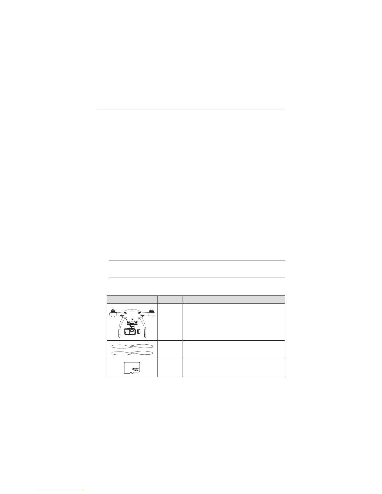
Table 2-1
Package Contents
Image Qty. Description
X1
Aircraft
Integrated with a 3-axis Gimbal and a
Camera (optional)
X4 Pair
Propeller
4 with red nut, 4 with white/black nut
X1
8GB MicroSD Card
Inserted in the Camera MicroSD card slot
8GB
4
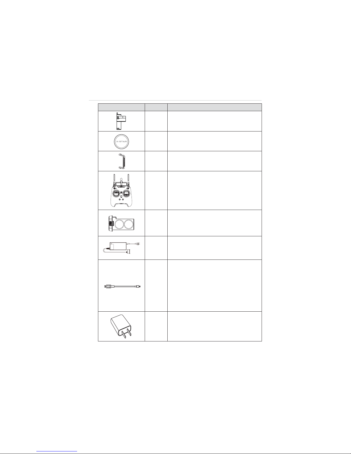
Image Qty. Description
X1
Gimbal Lock
Protects the Camera Gimbal when not in
use
X1
Lens Cap
Protects camera lens from dust and
scratches
X1
Gimbal Camera Securing Bracket
Secures the camera to the mount
X1
Remote Controller
Phone holder and 5000mAh Li-Ion battery
included
X1
Aircraft Battery
6400mAh Rechargeable Li-Po battery
Provides
ʈ
25 minutes of flight time if fully
charged.
X1
Aircraft Battery Charger
Connects the Aircraft Battery to the external
power port for AC/DC power supply
X1
Micro-USB Cable
z
Connects the Remote Control to the
USB Power Adapter for power supply;
z
Connects the Aircraft or the Remote
Control to the PC for firmware update or
configurations;
z
Connects the Camera Gimbal to the PC
for camera file transfer.
X1
USB Power Adapter
Connects to the external power port and
provides power supply to the Remote
Control through the Micro-USB Cable.
5
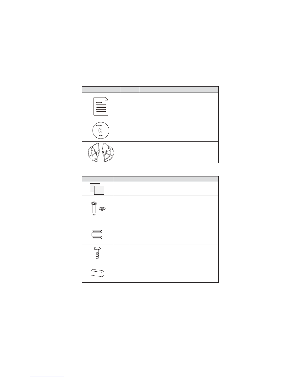
Image Qty. Description
X3
Manuals
z
User Manual
z
X-Star ST1 Quick Start Guide
z
Camera Mount Quick Start Guide (for
camera attached gimbals)
X1
CD
Includes PC Aid Program and User
Manual, etc.
Optional
Acc.
Propeller Guards
Surround the propellers and protect them
from damage. (4 in 1 set)
Aircraft Maintenance Kit
Image Qty. Description
X2
Indication Stickers
Helps pilots to identify the front side of the aircraft.
X2
Anti-drop Lock Pins
Fix the Camera Gimbal to the mounting rack
connected to the aircraft to avoid dropping.
2 pins mounted on deliver; 2 extra supplied for
maintenance use
X4
Vibration Absorber
Fixed in between the gimbal’s mounting rack and
the Gimbal to reduce vibrations and avoid
mechanical damage.
X11
Spare Screws
M3X5 (6pcs); M3X8 (5pcs)
X4
Rubber Pad
Stick to the 4 corners at the bottom of the landing
gear to support the aircraft when it is on the
ground, and when it is landing or taking off.
Autel Intelligent Technology Corp., Ltd.
All Rights Reserved
www.autel.com
PC Suite
Suitable for:
ವWindows 8
ವWindows 7
ವWindows Vista
:indows XP
6
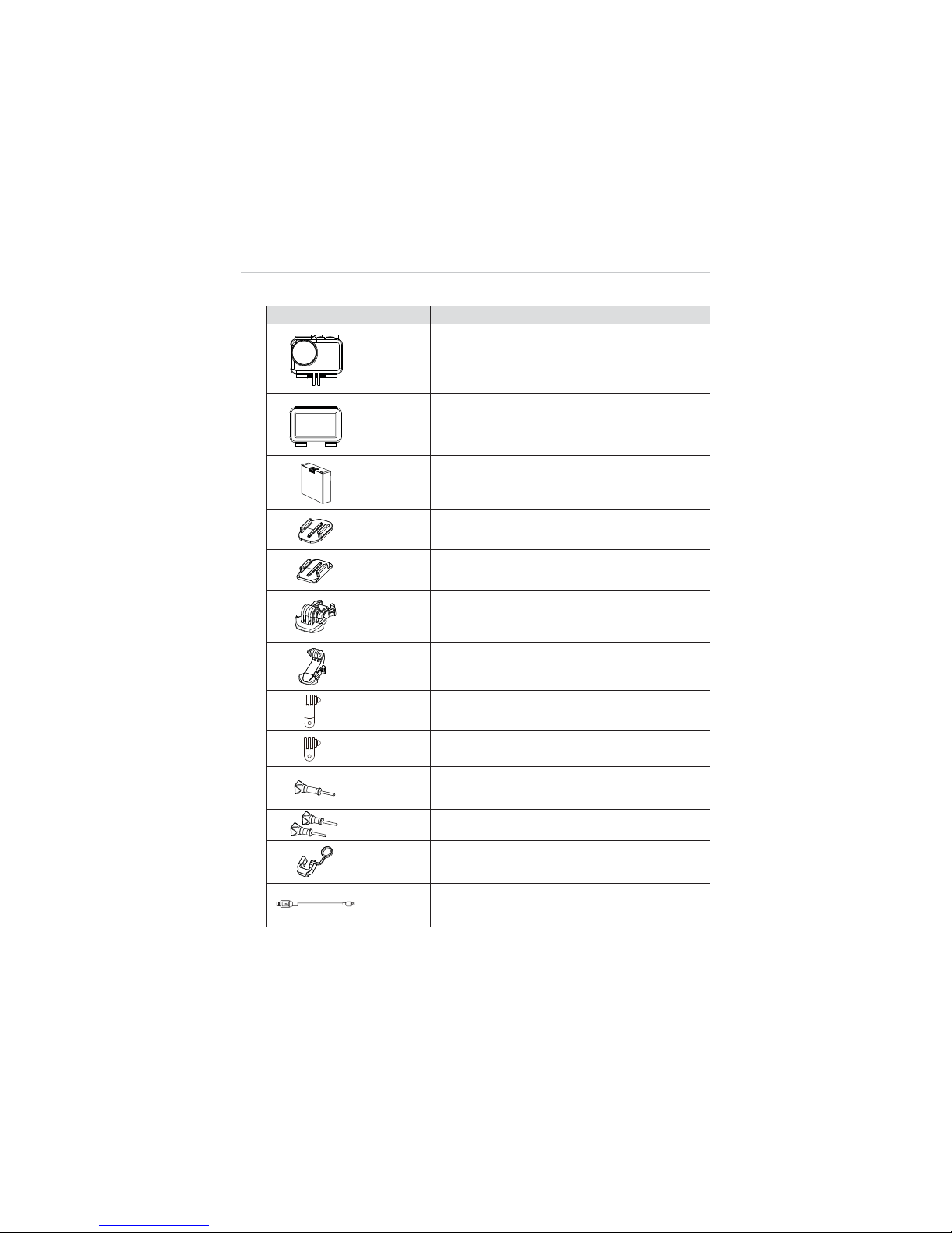
Camera Accessories Kit
Image Qty. Description
X1
Waterproof Housing
Allows underwater photographing.
X2
Backdoors
z
Opened (without cover, not waterproof)
z
Covered (with touchable screen protector)
X1
Camera Battery
940mAh Rechargeable Li-Po Battery installed on
delivery
X1
Flat Mount
X1
Curved Mount
X2
Short Connectors
X1
Long Connector
X1
90qC Rotate Connector (long)
X1
90qC Rotate Connector (short)
X1
Connecting Screw (long)
X2
Connecting Screws (short)
X1
Fixing Rubber
Prevents the Rotate Connector from slipping off.
X1
Mini USB Cable
Connects the Camera to the PC for file transfer.
7
2.2 Aircraft
The X-Star aircraft is a quadcopter with an integrated stabilized camera
gimba. The camera may or may not be supplied depending on the
gimbal model purchased. The Micro-USB port on the aircraft supports
convenient connection that allows easy flight configuration and system
update through the PC Aid Software.
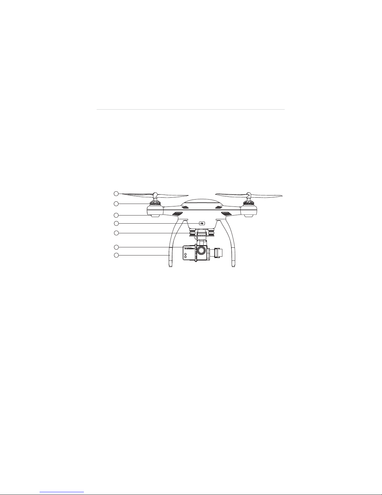
2.2.1 Functional Description
Figure 2-1
Front Side
1. Propeller – 9.4 x 4.3 inch
2. Motor
3. Front LED Indicator Light – helps to identify the aircraft nose
4. Micro-USB Port – allows communication between the Smart
Flight System and the PC Aid program through USB
connection
5. 3-axis Camera Gimbal
6. Camera
7. Front Sticker – helps to identify the aircraft nose
8
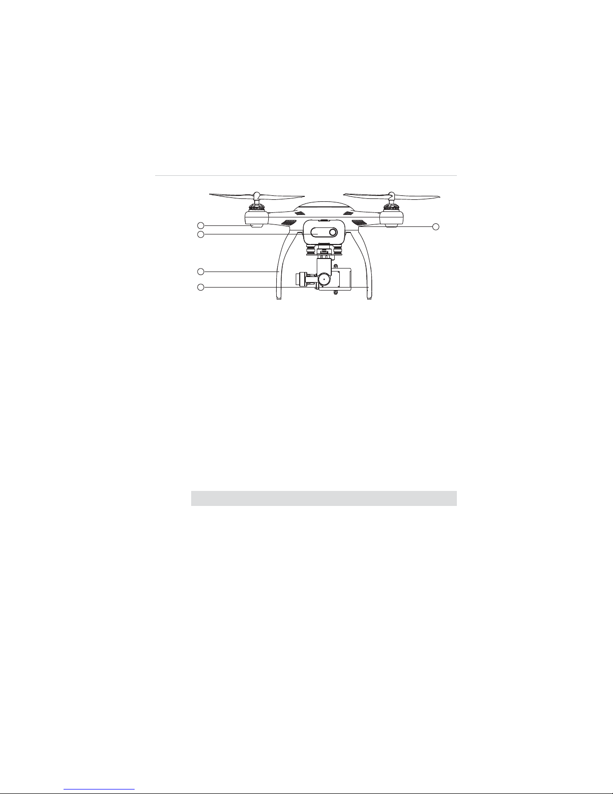
Figure 2-2 Rear Side
8. Rear LED Indicator Light – indicates flight status
9. Aircraft Battery
10. RC Pairing Button – prepares the aircraft to perform pairing
with the Remote Control, see 3.2.1 Re-pairing Remote
Controller on page 33 for detailed instructions
11. Landing Gear
12. Compass
Aircraft Specifications
Table 2-2 Aircraft Specifications
Item Descriptions
Max. Payload 0.8kg
Hover Precision Horizontal:
r
2m; Vertical: r1m;
Max. Yaw Rate 180
q
/s
Max. Inclination Angle GPS Mode: 30
q
; ATTI Mode: 30
q
Max. Ascent/Descent Speed Ascent: 6m/s; Descent: 2m/s
Max. Cruising Speed 12m/s
Diagonal Wheelbase 352mm

9
Item Descriptions
Propeller Size 9.4”x4.3”
WiFi Frequency 2.4GHz
Receiver Frequency 5.8GHz
Flight Modes
z
GPS
z
IOC
z
ATTI
z
Waypoint
Operating Environment Temperature0q
C~50qC(32qF~122qF)
Storage Temperature 0
q
C~45qC(32qF~113qF)
Weight (Battery & Propellers
included)
1.1kg
2.2.2 Built-in Smart Flight System
The X-Star features the Built-in Smart Flight System which
enables autopilot flight control that provides great ease of use and
stability. The Smart Flight System consists of various modules
such as the GPS receiver, the Compass and the Inertial
Measurement Unit (IMU). It works as the central computer of the
aircraft and supports various functions such as Intelligent
Orientation Control (IOC), Go Home, and Failsafe, etc.
Table 2-3 Smart Flight System Modules
Module Descriptions
IMU
An electronic device consists of a gyroscope,
accelerometer and magnetometer that measures flight
velocity, gravitational force and orientation.
Compass
Reads geomagnetic information and assists the GPS
receiver for accurate position calculation.
GPS Receiver
Receives GPS signals and determines the latitude and
longitude of the aircraft location.

10
Table 2-4 Smart Flight System Functions
Function Descriptions
IOC
Configures the aircraft to fly in the direction relative to
the home point or consistent to the initial aircraft
orientation, instead of its nose and tail.
Go Home
Commands the aircraft to return to and land on the
specified home point.
Failsafe
Enables the aircraft to take automatic protection
measure when communication with the remote control
is lost, to prevent damage or injuries.
NOTE:
A home point is usually memorized by the system each time as the
point where the aircraft takes off. The home point can also be repositioned
during flight. See 4.3.4 Operations of Smart Flight Features on page 49 for
details.
Table 2-5 Supported Flight Modes
Flight Modes Descriptions
GPS Mode
Stabilizes and holds the aircraft in position on stick
release when activated (requires at least 6 GPS satellite
signals)
, which offers more stable and smooth flight
maneuvers. It allows the safety features including Go
Home, IOC and Failsafe for safer flight experiences.
ATTI Mode
Stabilizes and holds the aircraft to the altitude on stick
release. The ATTI mode provides more agility in flight
controls with attitude and speed mixture. It allows the
safety features including Go Home, IOC and Failsafe for
safer flight experiences.
Manual Mode
Provides freer and more agile flight maneuvers
depending on 100% mechanical driving by controls of
the command sticks.
This mode is only recommended for experienced pilots,
and is disabled by default. It can be activated through
flight configurations with the PC Aid or X-Star Mobile
App.

11
2.2.3 Flight LED Indicator Light
The LED Indicator Lights on the aircraft can be found at both the
front and rear sides. The Front Indicators are mainly used for
helping pilots to identify the position of the aircraft nose, and the
Rear Indicators are used for showing the current flight status of
the aircraft.
The LED Indicator Lights will light up when the aircraft is turned on.
The table below describes the definitions of the LED Indicator
Light status.
Ș - Indicates solid light;
Ȗ – Indicates flashing light;
R – Indicates red colored light;
G – Indicates green colored light;
Y – Indicates yellow colored light
Example: “
R-
Ș
Ș
” sta
nds for
RED SOLID
light.
Table 2-6 Definitions of Flight LED Indicator Light Status
LED Indicator Status Descriptions
R-Ș(Front LEDs)
Light up when the motors start spinning
after the aircraft is powered on, indicating
the position of the aircraft nose.
G-Ȗ(Rear LEDs)
Displayed when in GPS Flight Mode. This
mode can be activated only when more
than 6 GPS satellites are found.
Y-Ȗ(Rear LEDs)
Displayed when in non-GPS Flight mode,
or when less than 6 GPS satellites are
found.
R-Ȗ-Slow
(Rear LEDs)
Displayed when communication with the
remote controller is lost.

12
LED Indicator Status Descriptions
R-
Ȗ
Ȗ
-Quick
(Rear LEDs)
Light up when battery voltage is less than
20%.
Y-Ȗ(Front & Rear LEDs)
Indicates compass calibration is required.
See 4.2
Calibrating Compass
on page
41 for detailed instructions.
Y-Ș(Rear LEDs)
Displayed during the 1
st
step of compass
calibration.
G-Ș(Rear LEDs)
Displayed during the 2
nd
step of compass
calibration.
R-Ȗ(Front & Rear LEDs)
Indicates hardware problems possibly
caused by:
z
IMU deviation or abnormal
z
Compass error
z
Remote Controller recalibration
required
See 5.2
Troubleshooting Checklist
on page 83 for detailed information.
2.2.4 Aircraft Battery
The Aircraft Battery is a rechargeable Li-Po Battery with the
capacity of 6400mAh specially designed for the X-Star aircraft. It
can only be charged by the charger supplied with the X-Star
package, and can provide sufficient power for about 25 minutes of
continuous flight if fully charged.
The Aircraft Battery features several smart functionalities for
charge-discharge management that improves the battery’s
longevity.

13
Table 2-7 Aircraft Battery Features
Feature Descriptions
Balancing
Balances the voltage of each battery cell to
prevent overcharging or over-discharging.
Communication
Retrieves and transfers battery info, including
battery level, current, voltage, battery life, and
temperature to the aircraft and the controller.
Charging Temperature
Detection
Stops battery charging when environment
temperature is out of allowed range.
Low Battery Protection
Activates alarm when battery level is less than
20%.
LED Capacity Indicator Indicates current battery level.
Overcharging &
Over-discharging
Protection
z
Automatically stops charging when battery
voltage reaches 12.8V to prevent damage.
z
Automatically stops discharging when
battery voltage reaches 8.4V to prevent
damage.
Short Circuit Protection
z
Cuts off power supply when a short circuit
occurs to prevent damage.
z
All LED lights on the battery front panel will
flash green w
hen a short circuit is
detected.
Power Saving
Turns the battery off automatically after 10
minutes of inactivity.
14
Aircraft Battery Specifications
Table 2-8 Aircraft Battery Specifications
Item
Descriptions
Battery Type
Rechargeable Li-Po Battery
Capacity
6400mAh
Battery Voltage
11.1V
Charging
Environment Temperature
0
q
C~40qC(32qF~104qF)
Discharging
Environment Temperature
-20
q
C~60qC(-4qF~140qF)
Storage Temperature & Humidity Temp: -10
q
C~45qC(14qF~113qF);
Humidity: 5~70%
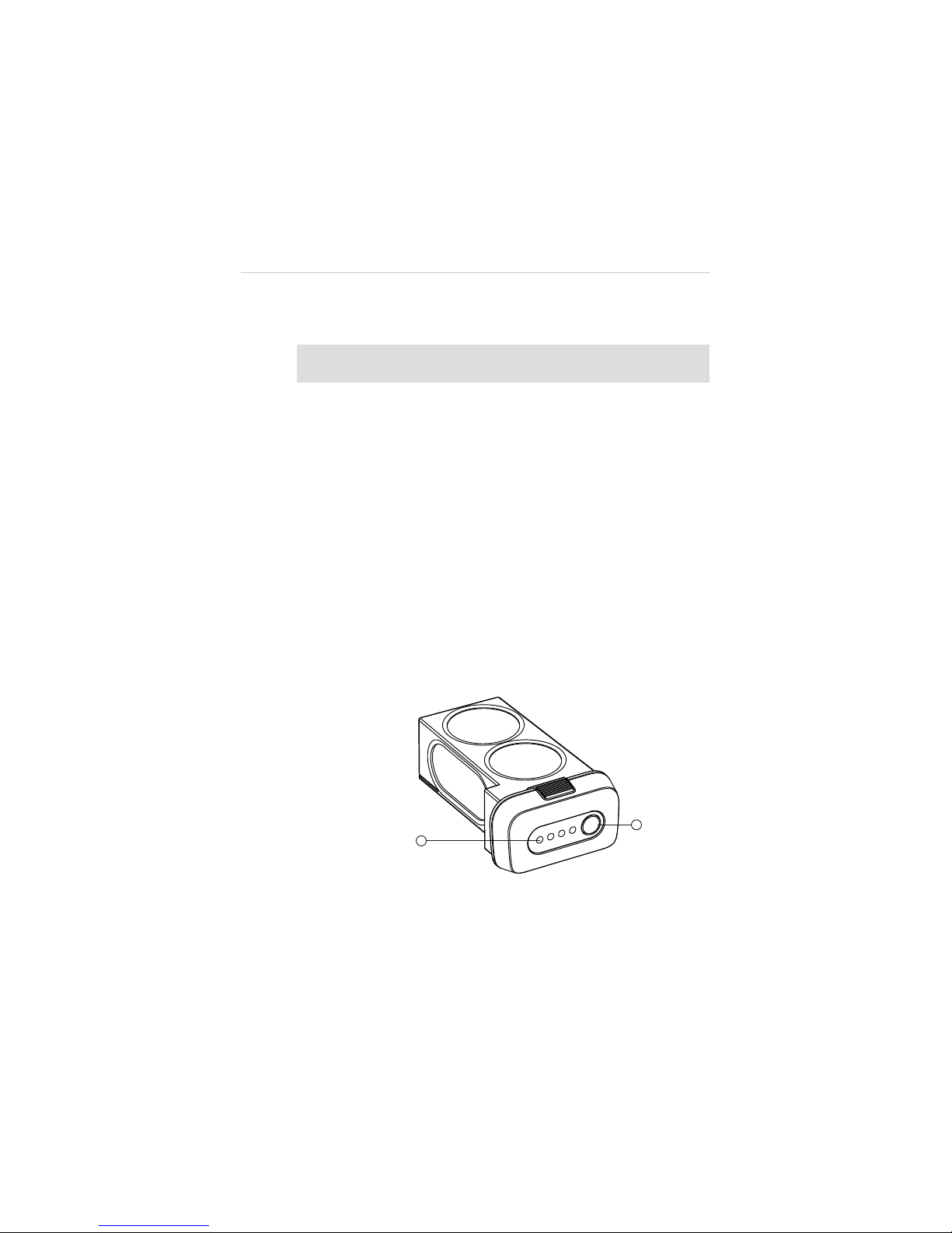
Functional Descriptions
The Aircraft Battery front panel contains 4 LED Capacity Indicator
Lights and 1 Power Button.
Figure 2-3 Aircraft Battery

15
1. Capacity Indicator Lights
2. Power Button – allows you to check the battery level and turn
on/off the battery
A. To turn on the battery and power up the aircraft, long
press the Power Button for 3 seconds. The Capacity
Indicator Lights will illuminate and indicate the current
battery level. (See Table 2-9 on page 15 for details.)
B. To turn off the battery, long press the Power Button for 3
seconds.
C. To check the current battery level when the battery is
powered off, short press the Power Button once, and
the Capacity Indicator Lights will illuminate and indicate
the current battery level.
The table below describes the specific battery levels indicated by
the Capacity Indicator Lights during discharging process.
Table 2-9
Capacity Indicator Status while Discharging
Ș
- Indicates solid green light; Ȗ- Indicates flashing green light
Indicator Status Battery Level
90%~100%
75%~89%
60%~75%
50%~60%
40%~50%
25%~40%
15%~25%
0%~15%
See 3.1.3 Charging Flight Battery on page 29 for more
details.
16
2.2.5 3-axis Camera Gimbal
The 3-axis Camera Gimbal mounted to the aircraft is specially
designed to allow smooth aerial photographing to minimize
camera vibration or shake.
It is powered through the Aircraft Battery, and therefore it is turned
on at the same time with the aircraft. A self-test is performed each
time the Gimbal starts up.
The X-Star system is compatible with more than one gimbal model.
Depending on the specific gimbal model purchased, the gimbal
may or may not have a camera mounted, and the camera, if
supplied, may or may not be detachable.
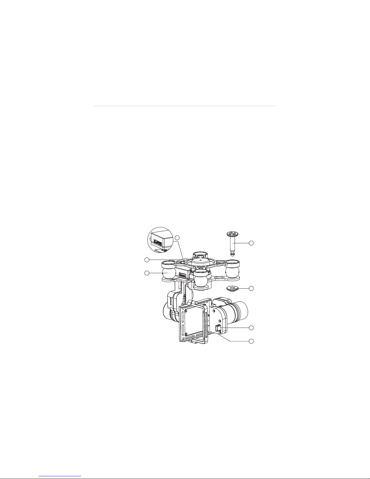
Figure 2-4
Standard 3-axis Camera Gimbal Sample
'
(

17
1. Mounting Rack
2. Vibration Absorber
3. Anti-drop Lock Pin
A. Press the pin through the hole at the corner of the
gimbal’s mounting rack with the Vibration Absorber in
between;
B. Press the stud from the bottom up to lock the pin.
4. Aircraft Communication Port
5. Camera Connector
6. Micro-USB Port – connects to the PC using the Micro-USB
cable supplied for camera file transfer. Do not disconnect the
camera from the gimbal while transferring.
Camera Gimbal Specifications
Table 2-10
Camera Gimbal Specifications
Item Descriptions
Operating Current
340mA@12V (Camera Off)
600mA@12V (Camera On)
Operating
Environment Temperature
0
q
C~45qC
Control Accuracy
Tilt/Roll:
r
0.02
q
Yaw:
r
0.03
q
Controllable Range
Pitch: 0
q
~90q(-130~+45°)
Maximum Angular Velocity
90
q
/s (r150°/S)
NOTE:
The Camera Gimbal comes with a gimbal lock attached
which protects the gimbal from incidental rotation to avoid damage.
Remove the clamp before powering up the aircraft (see
Figure 3-1
on page 27
).
18
The 3-axis Camera Gimbal for X-Star supports 2 working
modes:
1. FPV Mode – synchronizes the camera gimbal movements
with the aircraft to provide a real time video piloting
experience from a first-person view.
2. Non-FPV Mode – enables stabilized camera tilting control for
creative aerial photography.
See 4.4.4 Configuration Operations on page 67 for detailed
configuration instructions.
2.2.6 Camera
The Camera mounted to the Aircraft is stabilized by the 3-axis
Camera Gimbal. Depending on the gimbal’s working mode applied,
it enables both real time FPV piloting control and smooth aerial
photographing and video recording based on the pilot’s needs.
See 3-axis Camera Gimbal on page 16 for more information.
The Camera has a built-in Li-Po battery, which can be charged
either by the Aircraft Battery when mounted to the gimbal on the
aircraft, or by connecting to the PC using the Mini USB Cable
supplied.
Turn on the camera before powering up the aircraft.
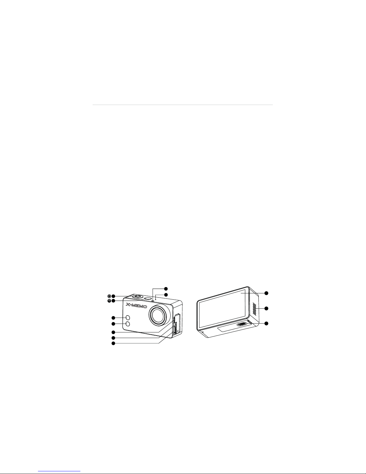
Figure 2-5
Camera 6-Side View
mode

19
1. Shutter/Select Button 2. Power/Mode Button
3. WiFi Status Light (blue) 4. Camera Status Light (red)
5. Micro HDMI Port 6. MicroSD Card Slot
7. Mini USB Port 8. LED Status Light
9. Microphone 10. Touch Screen
11. Audio Speaker 12. Battery Compartment Lock
Table 2-11
Camera Functional Descriptions
Name Description
1. Shutter/Select
Button
Press this button to:
A. Take photos or videos
B. Make selections on menus
2. Power/Mode Button
A. Press this button once to turn on the
camera.
B. Press and hold for 3 seconds to turn off
the camera.
C. When the camera is powered on,
pressing this button allows you to switch
among the camera
Modes
, the
Playback
and the
Setting
options in
sequence.
3. WiFi Status Light
(blue)
Indicates the WiFi communication status.
4. Camera Status
Light (red)
Indicates the working status of the camera
when taking photos or videos.
5. Micro HDMI Port
Connects the camera to a compatible
computer monitor, digital television, or video
projector for high definition video file transfer.
6. MicroSD Card Slot
Stores camera files.
7. Mini USB Port
Connects to and communicates with the
gimbal or the PC for file transfer.
8. LED Status Light
Synchronizes with the Camera and WiFi
Status lights for convenient identification.

20
Name Description
9. Microphone
Records sound when taking videos.
10. Touch Screen
Works as the display monitor featuring
intuitive touch control.
11. Audio Speaker
Makes alert sounds and plays audios.
12. Battery
Compartment Lock
Locks or unlocks the Battery Compartment.
Contains a 940mAh rechargeable Li-Po
battery.
NOTE:
The camera lens is covered by a lens cap on delivery to protect the
camera lens from dust and scratches. Remove the lens cap before use.
Camera Specifications
Table 2-12
Camera Specifications
Item Descriptions
Operating Environment Temperature -10qC~50qC(14qF~122qF)
Effective Pixels 12MP
HD Recording Resolution 1080P/60fps
Max. Recording Field of View 160
q
NOTE:
Refer to the supplied camera manual for more operation instructions.
2.3 Remote Controller
The X-Star Remote Controller enables wireless communication with the
Aircraft through a 5.8GHz radio frequency band. The maximum working
range of the Remote Controller through RF signal in an open area is
about 400m when set as CE compliant, or about 800m when set as
FCC compliant.
21
The built-in 2.4GHz WiFi module on the Remote Controller allows
self-generated WiFi network connection for real time flight and video
data transmission between the aircraft and the mobile device enabling
convenient controls of aerial photographing and remote piloting.
NOTE:
The X-Star WiFi Network is only established when the aircraft,
the Remote Controller and the mobile device are properly connected
through WiFi connection. See 3.3.3 Establishing X-Star WiFi Network
on page 35 for detailed instructions.
2.3.1 Functional Description
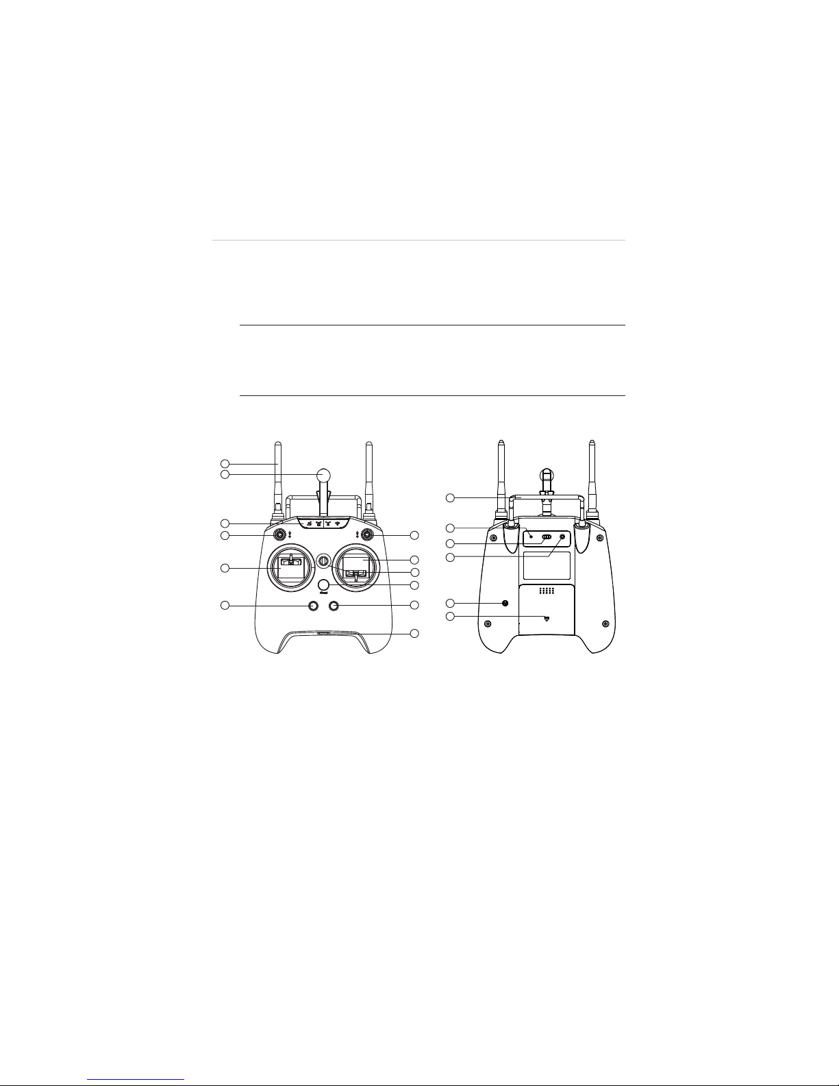
Figure 2-6
Remote Controller Front and Rear View
1. WiFi & RF Antennas 2. Mobile Holder
3. Indicator Light Panel 4. Smart Control Switch
5. Flight Mode Switch 6. Left Command Stick
7. Right Command Stick 8. Strap Hole
9. Power Button 10. Take-off Button
11. Landing Button 12. Micro USB Port
Re-Pair WiFi CE/FCC

22
13. Support Stand 14. Re-pair Hole
15. WiFi Switch 16. CE/FCC Control Screw
17. Buzzer 18. Battery Compartment
Table 2-13
Remote Controller Functional Descriptions
Name Description
1. WiFi & RF Antennas
z
The 5.8GHz RF signal antenna
communicates with and transmits control
signals to the aircraft.
z
The 2.4GHz WiFi antenna receives and
transfers flight data and camera data to
the X-Star Mobile App.
2. Mobile Holder
Holds the mobile device with the X-Star
Mobile App installed with up to 90
q
adjustable viewing angle for optimum
visibility.
3. Indicator Light Panel
Indicates different status of:
z
GPS satellite signal strength
z
Aircraft battery level
z
RF remote control signal strength
z
WiFi communication
See 2.3.2 Remote Controller Indicator Lights
on page 24 for detailed information.
4. Smart Control Switch
Switch to activate the Smart Flight function
of IOC or Go Home controls.
5. Flight Mode Switch
Switch to change flight modes:
Up: GPS Mode
Middle & Down: ATTI Mode

23
Name Description
6. Left Command Stick
Set by default:
Throttle Up and Down: ascends and
descends
Rudder Left and Right: yaws left and yaws
right
7. Right Command
Stick
Set by default:
Elevator Up and Down: forward and
backward
Aileron Left and Right: left and right
8. Strap Hole Attaches to a neck strap for easy portability.
9. Power Button
Long press for 3 seconds to turn on/off the
remote controller, a quick buzz can be heard
at the same time.
The power button shows solid green light
when the remote controller is turned on. See
2.3.2 Remote Controller Indicator Lights on
page 24 for detailed information.
10. Take-off Button
When the motors start up, pressing this
button for 3 seconds commands the aircraft
to take off and hover at an altitude of 2m.
A buzz sound can be heard at the same time
when activated.
11. Landing Button
Pressing this button for 3 seconds
commands the aircraft to land. A buzz sound
can be heard at the same time when
activated.
12. Micro USB Port
Connects the remote controller to the PC
through the Micro USB Cable supplied for
battery charging, firmware update or RC
configurations.
13. Support Stand
Holds up the remote controller at a 40
degree angle.
 Loading...