

MANUALE UTENTE - INSTALLATORE PER CLIMATIZZATORE PORTATILE
IT
PORTABLE AIR CONDITIONER USER’S – INSTALLER’S MANUAL
EN
MODELLI / MODELS
N-P35A2, P35A2
Questo manuale è stato creato per scopo informativo. La ditta declina ogni responsabilità per i risultati di una progettazione o di una installazione
basata sulle spiegazioni e le specifiche tecniche riportate in questo manuale. E’ inoltre vietata la riproduzione anche parziale sotto qualsiasi forma
dei testi e delle figure contenute in questo manuale.
This manual has been created for informative purposes. The company declines any responsibility for the
results of projects or installations based on
the explanations and the technical specifications provided in this manual. It is besides forbidden the reproduction under any form of the texts and of
the figures contained in this manual.
1
Serie / Series / Serie / Serie / Série
MANUALE UTENTE-INSTALLATORE
USER’S-INSTALLER’S MANUAL
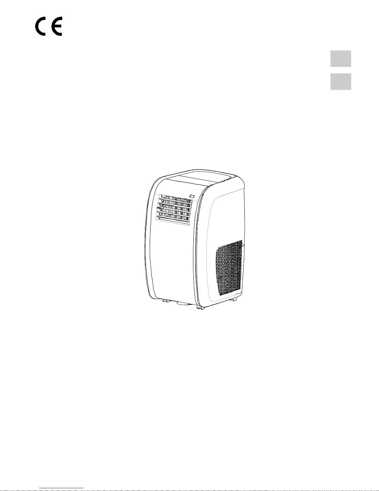
CLIMATIZZATORE PORTATILE
PORTABLE AIR CONDITIONER
Emissione / Issue
01 - 2013
Catalogo / Catalogue / Catálogo / Katalog / Catalogue
MUI14008D0001-00
Sostituise / Supersedes
-
I prodotti elettrici ed elettronici di eventuale scarto non dovranno essere disposti con i
normali rifiuti domestici, ma smaltiti a norma di legge RAEE in base alle direttive Europee
2002/96/CE e suc-cessive modifiche 2003/108/CE, informandosi presso il Comune di
residenza o presso il rivenditore nel caso in cui il prodotto venga sostituito con uno analogo.
Possible electrical or electronic rejected devices/products should not be located together with
normal domestic waste, but disposed according to the current WEEE law in compliance with
the 2002/96/EC European Directive and with the 2003/108/EC following amendments.
Should you decide to replace this product with a new one, please, address your loca
l
A
dministration or your reseller.

2
INDICE
■ INFORMAZIONI SULLA SICUREZZA ...........................................................................................3
■ TELECOMANDO............................................................................................................................ 4
■ DESCRIZIONE DEI COMPONENTI DELL’APPARECCHIO..........................................................8
■ PANNELLO DI CONTROLLO DELL’APPARECCHIO ..................................................................8
■ INDICATORI DEL DISPLAY LCD ..................................................................................................8
■ FUNZIONI DEL PANNELLO DI CONTROLLO .............................................................................. 8
■ ISTRUZIONI PER L’UTILIZZO .......................................................................................................9
■ ISTRUZIONI PER L’INSTALLAZIONE......................................................................................... 10
■ ASSISTENZA E MANUTENZIONE .............................................................................................. 16
■ MALFUNZIONAMENTI................................................................................................................. 17
ANNESSO .......................................................................................................................................33
■ SCHEMA ELETTRICO .................................................................................................................33
ITALIANO

3
■ INFORMAZIONI SULLA SICUREZZA
1. Il portatile funziona con alimentazione 220V-240V AC / 50 Hz, la capacità dell’interruttore del circuito è 16A .
2. Usare una presa adatta e non collegata ad altre apparecchiature elettriche.
3. Non posizionare l’apparecchio nei seguenti luoghi:
- vicino ad una fonte di calore;
- in un’area dove è facile che dell’olio schizzi;
- in un’area esposta direttamente alla luce solare;
- in un’area dove è facile che dell’acqua schizzi;
- vicino ad un bagno, ad una doccia, ad una piscina;
- in una serra.
4. Non infilare le vostre dita o qualsiasi altro oggetto all’interno delle bocche d’uscita dell’aria: fare attenzione in
particolare ai bambini.
5. Controllare sempre che l’apparecchio lavori in condizioni appropriate.
6. Assicurarsi che l’unità non sia alimentata prima di pulirla.
7. Non collegare la macchina ad una presa multipla
8. Se la macchina viene coperta c’è il rischio che si crei un incendio.
9. Se un componente della macchina è danneggiato deve essere sostituito con un componente appropriato fornito dal
produttore, in quanto sono richiesti componenti specifici.
ATTENZIONE!
Se il cavo di alimentazione si danneggia contattare il personale qualificato ed autorizzato a fare questa riparazione.

4
■ TELECOMANDO
◊ Introduction of function buttons on the remote controller
① Tasto ON/OFF, consente di spegnere e accendere il condizionatore.
② Tasto MODE permette di selezionare la modalità di funzionamento: AUTO - COOL- DRY -
FAN - HEAT.
③, ④ Tasti di regolazione (-/+) consentono di regolare la temperatura ambiente interna ed il
timer: "+" ne imposta l'aumento, "-" ne imposta la diminuzione.
⑤ Tasto FAN permette di selezionare la velocità della ventilazione: Auto, Bassa (
), Bassa –
Media (
), Media ( ), Media – Alta ( ), Alta ( ).
Auto
⑥ Tasto SWING
, per attivare/disattivare il movimento automatico del deflettore d'aria.
⑦ Tasto HEALTH / SAVE per impostare la funzione di purificazione aria.
⑧ Tasto SWING
, per attivare o disattivare la funzione oscillazione sinistra & destra del
deflettore d‘aria. (questa funzione non disponibile in questo modello.)
⑨ Tasto X-FAN consente di avviare / arrestare il ventilatore interno, questa funzione si utilizza
per asciugare i componenti dell'unità interna.
⑩ Tasto TEMP permette di visualizzare sul display dell’unità la temperatura di set point o
ambiente.
⑪ Tasto TIMER consente di impostare l’orario di accensione / spegnimento in automatico.
⑫ Tasto TURBO attiva/disattiva la modalità di raffreddamento e riscaldamento rapido.
⑬ Tasto SLEEP, usato per impostare/cancellare la modalità SLEEP, indipendentemente dal
modo in cui sta operando il condizionatore.
⑭ Tasto LIGHT per accendere o spegnere il display dell’unità.
FAN
AUTO
O
P
E
R
HEALTH
AIR
FILTER
TURBO
ON/OFF
X-FAN
HOUR
HUMIDITY
ON/OFF
MODE
FAN
X-FAN
TURBO
TEMP
TIMER
SLEEP
LIGHT
2
11
7
10
13
9
43
12
8
6
14
5
1
◊ Name and functions of the display indicators
: Indicatore modalità automatica
: Indicatore modalità di raffreddamento
: Indicatore modalità di deumidificazione
: Indicatore modalità modalità di ventilazione
: Indicatore modalità di riscaldamento
: Indicatore modalità SLEEP
: Indicatore modalità TIMER ON-OFF
: Indicatore modalità temperature ambiente
: Indicatore funzione LIGHT
: Indicatore modalità funzione LOCK
: Indicatore oscillazione deflettore di aria
: LED conferma trasmissione segnale.
FAN
: Indicatore modalità velocità di ventilazione
: Indicatore modalità di temperatura di impostazione
: Icona oscillazione sinistra & destra, premere il tasto per selezionare la funzione
SWING, il deflettore dell’aria si muoverà verso sinistra & destra ed il display visualizza
,
ripremedo lo stesso tasto l’icona
scompare dal display e la funzione si disattiva.
DISPLAY
FAN
AUTO
O
P
E
R
HEALTH
AIR
FILTER
TURBO
ON/OFF
X-FAN
HOUR
HUMIDITY

5
◊ Come inserire/sostituire le batterie
Usare due batterie alcaline 1,5 V tipo AAA.
(1) Rimuovere il coperchio delle batterie facendolo scivolare nella direzione della freccia.
Rimuovere le batterie vecchie e inserire le nuove facendo attenzione ad allineare
correttamente le polarità (+) e (-).
(2) Chiudere il coperchio delle batterie facendolo scivolare nella sua posizione.
Note:
- Non mettere insieme batterie nuove con vecchie o batterie di tipo differente. Ciò può
essere causa di malfunzionamento.
- Se non si usa il telecomando per un lungo periodo, le batterie devono essere tolte per
evitare danni causati da eventuali perdite.
- Le batterie vanno sostituite quando non si riceve alcun "bip" dall’unità interna o se
l’indicatore di trasmissione sul telecomando non si accende.
- Posizionare il telecomando nell’apposito supporto fissato a muro (per assicurare la
trasmissione corretta del segnale).
◊ Come utilizzare il telecomando per far funzionare l’unità
● ACCENSIONE SPEGNIMENTO DELL’UNITÀ
Premere il tasto
per accendere o spegnere l’unità.
● IMPOSTAZIONE DELLA MODALITÀ DI FUNZIONAMENTO
Premendo più volte il tasto Mode è possibile cambiare la modalità di funzionamento dell’unità. Sul display compare
l’indicazione della modalità di funzionamento selezionato:
→ → → →
: funzionamento completamente automatico
: funzione raffreddamento
: funzione deumidificazione
: funzionamento solo ventilazione
: funzione riscaldamento
Con la scelta della modalità AUTO ’’
’’, l’unità può operare in RAFFREDDAMENTO ‘’ ’’ ed in RISCALDAMENTO
‘’
’’ in base alla differenza di temperatura esistente tra la temperatura ambiente e la temperatura selezionata sul
telecomando.
Quando viene scelta la modalità di raffreddamento, l’unità funziona con set di temperatura libero, abbassando la
temperatura in ambiente.
Quando viene scelto la modalità di deumidificazione, l’unità funziona, con set di temperatura libero, abbassando così
progressivamente la temperatura e l’umidità in ambiente. Nella modalità di deumidificazione il tasto FAN non è
utilizzabile.
Quando viene scelto il programma di riscaldamento, l’unità funziona, con set di temperatura libero, alzando la
temperatura in ambiente. Quando viene scelta la modalità di ventilazione FAN ‘’
’’, l’unità funziona senza set di
temperatura, ventilando l’aria dell’ambiente.
IMPORTANTE!
♦ Il ventilatore dell’unità si ferma al raggiungimento del valore di temperatura impostato per poi riattivarsi
automaticamente alla velocità minima per evitare fenomeni di stratificazione dell’aria in prossimità
dell’apparecchio.
♦ Selezionando la funzione RAFFREDDAMENTO, DEUMIDIFICAZIONE, il ventilatore potrebbe non
avviarsi subito perché presente la funzione ANTI-RISCALDAMENTO. Selezionando la funzione
riscaldamento, il ventilatore potrebbe non avviarsi subito perché presente la funzione ANTIRAFFREDDAMENTO.
● IMPOSTAZIONE DELLA VENTILAZIONE
Premendo più volte il tasto FAN è possibile impostare la velocità del ventilatore tra le tre disponibili, oppure attivare la
funzione AUTO. Sul display compare la modalità di funzionamento:

6
Auto
Velocità Auto, Velocità Bassa ( ), Velocità Bassa-Media ( ), Velocità Media ( ), Velocità Media-Alta ( ),
Velocità Alta (
).
● IMPOSTAZIONE DEL DEFLETTORE
Per ottenere una distribuzione ottimale dell’aria, regolare la posizione del deflettore motorizzato avendo cura che il
flusso d’aria non investa direttamente le persone. Per il deflettore motorizzato agire nella modalità seguente:
Premendo il tasto
è possibile selezionare l’angolo di oscillazione come indicato sotto:
OF
F
Note: Questo telecomando è universale. Se il comando non viene inviato all’unità, essa attiva l’oscillazione del
deflettore come
.
Il simbolo
indica che il deflettore oscilla come:
● Funzione HEALTH | SAVE
Questo tasto
HEALTH | SAVE
è usato per attivare/disattivare la modalità di depurazione aria/risparmio energetico
quando il condizionatore è in funzione.
- Premendo la parte destra del tasto, sul telecomando si visualizza la scritta SE dopodiché, l’unità entra in modalità
‘’SAVE’’
(risparmio energetico).
- Ripremendo il tasto, la modalità viene annullata.
Nota: non disponibile in questa unità.
● Impostazione oscillazione
♦
Premere il tasto per attivare o disattivare la funzione oscillazione sinistra & destra. (questa funzione non
disponibile in questo modello.)
Nota: Questa funzione non’è comunque disponibile per questa unità.
● FUNZIONE X-FAN
Se il tasto
X-FAN
viene premuto durante il funzionamento di
RAFFREDDAMENTO
o
DEUMIDIFICAZIONE
, il display
visualizza l'indicatore
ed il ventilatore interno continua a girare per altri 10 minuti per asciugare l’interno dell’unità,
anche se essa è stata spenta.
Al momento dell’accensione dell’unità, la funzione
X-FAN OFF
è l’impostazione predefinita di fabbrica.
X-FAN
è
disattiva nel funzionamento in modalità
AUTO, VENTILAZIONE o RISCALDAMENTO.
● FUNZIONE TEMP
Tasto TEMP permette di visualizzare sul display dell’unità la temperatura di impostazione, ambiente interna e
ambiente esterna.
Note: La temperatura ambiente esterna viene visualizzata sul display solamente per alcuni modelli.
●
IMPOSTAZIONE DEL TIMER
Utilizzare il tasto TIMER per impostare la programmazione oraria e quindi l’accensione e lo spegnimento del
condizionatore.
- Come impostare TIMER ON
Premere il tasto TIMER per impostare la programmazione oraria dell’accensione del condizionatore.
1) Premere il tasto TIMER, la scritta "HOUR ON" comincia a lampeggiare, dopodiché usare i tasti ''+'' e ''-'' per
impostare l’ora desiderata per l’accensione programmata del condizionatore:
- Premere il tasto ''+'' o ''-'' una volta per aumentare o diminuire l’orario di 1 minuto.
- Premere il tasto ''+'' o ''-'' per una durata di 2 secondi per aumentare o diminuire l’orario di 10 minuti.
Nota: Se non regolate l'orario entro 10 secondi dopo aver premuto il tasto TIMER, il telecomando abbandonerà
automaticamente la modalità TIMER ON.
2) Per confermare l'orario desiderato, premere il tasto TIMER. Un “suono” può essere sentito, e la scritta “HOUR ON”
smette di lampeggiare.
- Come cancellare TIMER ON
Premere di nuovo il tasto TIMER, "un suono" può essere sentito dopodiché l'indicatore sparisce, e la modalità TIMER
ON verrà cancellata.

7
Nota: È analogo per impostare la modalità TIMER OFF per spegnere automaticamente il condizionatore all'ora
impostata.
● MODALITÀ TURBO
- La modalità TURBO è usata per avviare o arrestare il raffreddamento e il riscaldamento rapido a massima velocità di
impostazione.
- In questa modalità TURBO, si possono regolare la direzione del flusso d'aria e il timer. Se si desidera uscire dalla
modalità TURBO, è sufficiente premere un tasto qualsiasi tra - TURBO, MODE, FAN o ON/OFF, il display ritorna alla
modalità originale.
● MODALITÀ SLEEP
La modalità "SLEEP" può essere impostata nel funzionamento di riscaldamento o di raffreddamento.
Questa funzione è utile per un ambiente più confortevole quando si va a dormire.
Nella modalità SLEEP:
- La velocità del ventilatore viene impostata sulla bassa.
- La temperatura impostata aumenta (diminuisce) di 1°C se il condizionatore funziona in modalità di raffreddamento
(riscaldamento). Quando la temperatura impostata varia con 2°C la macchina mantiene la temperatura fino all’ottava
ora di funzionamento in modalità “SLEEP”, per poi spegnersi automaticamente.
● FUNZIONE LIGHT
Premere il tasto
LIGHT
per accendere la luce del display e si mostra l’indicatore LIGHT
. Premere nuovamente per
spegnerlo dopodiché l’indicazione
scompare dal display.
● FUNZIONE LOCK
Premendo contemporaneamente i tasti "+" e "-", il telecomando bloccherà l’ultima operazione impostata.
Tutti i tasti di comando vengono disattivati, incluso il tasto di accensione / spegnimento ON/OFF. Premendo
nuovamente i due tasti "+" e "-", si riattiveranno le funzioni dei tasti.
● Commutazione tra °C e °F
Premendo contemporaneamente i due tasti "MODE" e "-" ad unità spenta, si potrà scegliere se visualizzare la
temperatura in °C o °F.
8
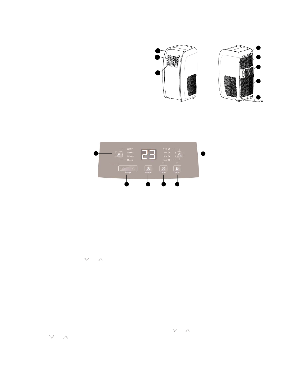
■ DESCRIZIONE DEI COMPONENTI DELL’APPARECCHIO
n Pannello di controllo;
o Uscita aria;
p
Ricevitore per segnale telecomando;
q
Maniglia per il trasporto;
r Griglia ingresso aria superiore;
s Uscita aria calda;
t Griglia ingresso aria inferiore;
u Cavo di alimentazione elettrica
NOTA: tutte le immagini sono soltanto un esempio
illustrativo utile alla spiegazione e possono essere
lievemente diverse dall’apparecchio che avete
acquistato.
Vista anteriore
1
2
3
Vista posteriore
4
5
6
7
8
■ PANNELLO DI CONTROLLO DELL’APPARECCHIO
L'unità può essere controllata dal pannello di comandi dell'apparecchio o con il telecomando.
NOTA: le immagini in questo manuale sono soltanto un esempio illustrativo utile alla spiegazione e possono essere
lievemente diverse dall’unità che avete acquistato (a seconda del modello) mentre le relative funzioni sono le stesse.
■ INDICATORI DEL DISPLAY LCD
13
3
65
2
■ FUNZIONI DEL PANNELLO DI CONTROLLO
n Tasto Power:
Tasto Accensione/Spegnimento
o Tasto MODE
Premere questo tasto per selezionare la modalità di funzionamento appropriata:
COOL Î DRY Î FAN Î HEAT
COOL: Modalità raffreddamento;
DRY: Modalità Deumidificazione;
Fan: Modalità ventilazione;
HEAT: Modalità riscaldamento
p Tasti di regolazione " " e " ":
Questi tasti vengono usati in modalità di raffreddamento o riscaldamento per impostare (incrementare/decrementare)
la temperatura desiderata (incrementi/decrementi ad ogni pressione 1°C(°F) nell’intervallo (16°C - 30°C / 61°F - 86°F).
q Tasto Fan:
Premere il tasto FAN per selezionare la velocità di ventilazione desiderata:
LOW Î MED Î TURBO Î AUTO
LOW: Velocità bassa;
MED: Velocità medea
TURBO: Velocità massima
AUTO: Velocità automatica
r Tasto Timer:
Premere il tasto Timer per impostare la funzione Timer. Usare il tasto "
" o " " per regolare l’ora del Timer. Premere
il tasto "
" o " " per aumentare o diminuire l'impostazione del tempo di 0.5 ore. L’intervallo di programmazione è
0,5~24 ore. Dopo aver completato l’impostazione del timer, il display visualizza la temperatura per 5 secondi. Se
l’impostazione è attiva, l’indicatore superiore rimarrà acceso, altrimenti, esso scomparirà dal display.
9
Per programmare lo spegnimento della macchina seguire la stessa procedura ma a macchina accesa. Per annullare
la modalità Timer, premere di nuovo lo stesso tasto.
s Tasto Sleep:
Premere il tasto SLEEP per attivare la modalità SLEEP. In raffreddamento, dopo l’attivazione della funzione SLEEP,
la temperatura di impostazione aumenta di 2°C dopo 2 ore poi rimane stabile per tutto il tempo di operazione. In
riscaldamento, dopo l’attivazione della funzione SLEEP, la temperatura di impostazione diminuisce di 2°C dopo 2 ore,
dopodiché rimane stabile per tutto il tempo di operazione. La funzione SLEEP non è disponibile in modalità AUTO,
Deumidificazione e Ventilazione. Se l’impostazione SLEEP è valida, l’indicatore superiore rimane acceso, altrimenti,
esso scomparirà dal display.
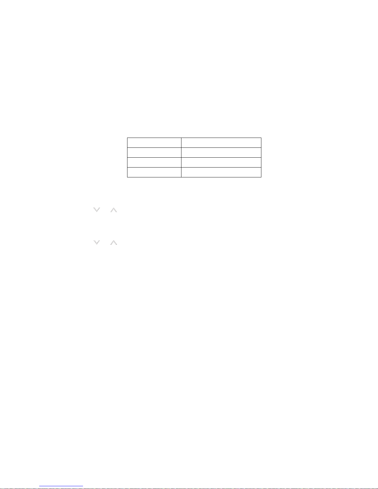
■ ISTRUZIONI PER L’UTILIZZO
◊ Condizioni operative
Condizioni di temperatura ambiente richieste per il funzionamento del condizionatore.
Modalità Temperatura interna °C/°F
Raffreddamento 16°C ~ 35°C / 61°F ~ 95°F
Deumidificazione 16°C ~ 35°C / 61°F ~ 95°F
Riscaldamento 10°C ~ 27°C / 50°F ~ 80.6°F
◊ Modalità di funzionamento
● Modalità di raffreddamento
1) Premere il tasto “MODE” finché s’illumina il LED “COOL”.
2) Premere il tasto "
" o " " per selezionare la temperatura desiderata (16°C ~ 30°C / 61°F ~ 86°F).
3) Premere “FAN” per scegliere la velocità del ventilatore.
● Modalità di riscaldamento
1) Premere il tasto “MODE” finché s’illumina il LED “HEAT”.
2) Premere il tasto "
" o " " per selezionare la temperatura desiderata (16°C ~ 30°C/61°F ~ 86°F).
3) Premere "FAN" per scegliere la velocità del ventilatore.
● Modalità di deumidificazione
1) Premere il tasto “MODE” finché s’illumina il LED “DRY”.
2) La velocità di ventilazione e la temperatura d’impostazione non possono essere aggiustate in questa modalità. Il
ventilatore girerà alla velocità bassa.
3) Tenere finestre e porte chiuse per avere i migliori risultati.
4) Non installare il tubo di scarico aria sulla finestra.
● Modalità di ventilazione
1) Premere il tasto “MODE” finché s’illumina il LED “FAN”.
2) Premere "FAN" per scegliere la velocità del ventilatore.
3) Non installare il tubo di scarico aria sulla finestra.
● Funzione TIMER
- Impostazione del TIMER per l’accensione:
- Premere il tasto "TIMER" quando il condizionatore è spento. Selezionare l’orario di accensione automatica del
condizionatore. Sulla finestra di controllo del display comparirà la scritta "ON".
- L’orario impostabile per le operazioni va da 00:00 a 24:00.
- Impostazione del TIMER per lo spegnimento:
- Premere il tasto "TIMER" quando il condizionatore è acceso. Selezionare l’orario di spegnimento del condizionatore.
- Sul display del pannello di controllo comparirà la scritta "OFF". L’orario impostabile per le operazioni va da 00:00 a
24:00.
10
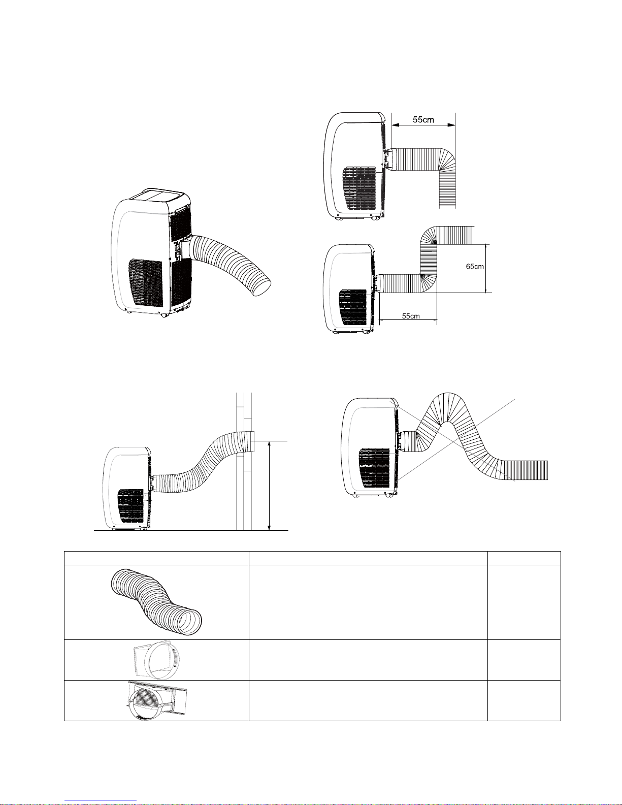
■ ISTRUZIONI PER L’INSTALLAZIONE
Accessori e installazione del tubo di scarico dell'aria calda
- Se si deve piegare il tubo, è necessario installarlo
considerando le seguenti dimensioni sotto.
- La lunghezza del tubo deve essere compresa tra 50 e
150cm. Il tubo di scarico aria calda deve essere più corto
possibile.
- Quando si installa il tubo di scarico aria, esso deve
essere collocato in modo che sia più piatto. No estendere
o collegare il tubo con un altro tubo di scarico per evitare
malfunzionamenti.
- La figura qui sotto mostra come installare correttamente
l'unità (se viene installata al muro, l'altezza dovrebbe
essere di circa 40-100cm dal pavimento).
100cm
- La figura qui sotto mostra un esempio di installazione
non corretta (Un tubo troppo piegato può essere causa di
malfunzionamenti dell'unità).
◊ Accessori
COMPONENTI DESCRIZIONE Q.tà
Tubo scarico aria di lunghezza 50-150cm. 1 set
Estremità frontale tubo plastica 1 pc
Adattatore finestra tubo di scarico 1 pc

11
◊ Installazione dell’unità
● Collocazione
- Collocare l'apparecchio su una superficie piana e stabile per minimizzare
rumore e vibrazione. Assicurarsi che la sua posizione sia stabile.
- L'apparecchio è dotato di rotelle permettendo di spostarlo facilmente, le
rotelle devono scorrere soltanto su superfici lisce e piane. Si consiglia di
fare attenzione in caso di spostamento su tappeti. Non spostare
l'apparecchio su ostacoli.
- Selezionare una posizione adeguata permettendo di accedere facilmente
a una presa elettrica.
- Non appoggiare oggetti sulle griglie di ingresso/uscita dell'aria.
- Lasciare almeno 50cm di distanza dalla parete, per migliorare l’efficienza
di condizionamento.
min.
min.
Fig. 4
● Installazione in una doppia finestra a ghigliottina appesa
1) Fissaggio riparo al pannello finestra
Spingere saldamente il riparo rete anti-insetti per assicurare l’inserzione
delle quattro proiezioni nei fori del kit pannello per finestra.
2. Tagliare il nastro di gomma (tipo adesivo) A fino alla lunghezza
adeguata, quindi fissarlo al telaio della finestra.
Nastro di gomma A
(tipo adesivo)
3. Fissare il kit pannello per finestra al telaio della finestra.
- Se la larghezza interna della finestra è compresa tra 22 "(559 mm) e
24"(609 mm).
Aggiustare la lunghezza del kit in base alla larghezza della finestra,
accorciare il kit regolabile, se la larghezza della finestra è inferiore di 22
pollici / 559mm.
Aprire la finestra a ghigliottina e posizionare il cursore del kit sul telaio della
finestra.
Tagliare
Coperchio di scarico
K
i
t
p
an
ne
l
l
o
f
i
ne
s
t
r
a
P
a
n
n
e
l
l
o
r
e
g
o
l
a
b
i
l
e
1) Rimuovere il pannello di regolazione dal kit pannello per finestra, e tagliare
pannello finestra alla stessa larghezza della finestra.
2) Aprire la finestra a ghigliottina e posizionare il kit pannello per finestra sul
telaio della finestra.
3) Fissare il kit pannello per finestra alla ghigliottina della finestra con 2 viti.
Kit pannello per finestra
22"~ 24 "
Telaio finestra
- Se la larghezza interna della finestra è compresa tra 24"(609mm) e
36.8"(934mm).
1) Aprire la finestra a ghigliottina e posizionare il kit pannello per finestra sul
telaio della finestra.
(2) Far scorrere il pannello di regolazione in modo da adattarlo alla
larghezza del telaio della finestra.
3) Fissare il kit pannello per finestra al telaio della finestra con 3 viti.
Pannello di regolazione
24"~36.8"

12
- Se la larghezza interna della finestra è compresa tra 36.8"(934mm) e
48"(1219mm).
(1) Fissare il pannello di estensione al pannello di regolazione.
(2) Aprire la finestra a ghigliottina e posizionare il kit pannello per finestra
sul telaio della finestra.
(3) Far scorrere i pannelli di regolazione e quello di estensione in modo da
adattarli alla larghezza del telaio della finestra.
(4) Fissare il kit pannello per finestra al telaio della finestra con 4 viti.
Pannello di estensi one
36.8"~48"
4. Tagliare il nastro adesivo di gomma (A) fino alla lunghezza
adeguata, poi fissarlo al kit pannello per finestra.
5. Fissare saldamente il telaio della finestra contro il kit pannello per
finestra.
6. Tagliare il nastro di gomma fino alla lunghezza adeguata, quindi
fissarlo all’apertura tra la parte interna e la parte superiore del telaio
della finestra.
Nastro di gomma A
(tipo adesivo)
7. Fissare un supporto con vite.
Supporto
● Installazione in una finestra scorrevole a ghigliottina
1) Fissaggio griglia di protezione al pannello finestra
Spingere saldamente la griglia di protezione (anti-insetti) per assicurare
l’inserzione delle quattro proiezioni nei fori del pannello finestra.
Pr oiezione
2. Tagliare il nastro di gomma (tipo adesivo) A fino alla lunghezza
adeguata, quindi fissarlo al telaio della finestra.
Nastro di gomma A
(tipo adesivo)
3. Fissare il kit per finestra al telaio della finestra.
- Se l’altezza interna della finestra è compresa tra 22"(559mm) e
24"(609mm).
Aggiustare la lunghezza del kit in base alla larghezza della finestra,
accorciare il kit regolabile, se la larghezza della finestra è inferiore di
22’’(559mm).
(1) Rimuovere il pannello di regolazione dal kit pannello per finestra, e
tagliare il pannello finestra alla stessa altezza della finestra.
(2) Aprire la finestra a ghigliottina e posizionare il kit pannello per finestra
sul telaio della finestra.
(3) Fissare il kit pannello per finestra allo ghigliottina della finestra con 2 viti.
Tagliare
Coperchio di scarico
K
i
t
p
a
n
n
e
l
l
o
f
i
n
e
s
t
r
a
P
a
n
n
e
l
l
o
r
e
g
o
l
a
b
i
l
e
Pannello per finest ra
22"~24"

13
- Se l’altezza interna della finestra è compresa tra 24"(609mm) e
36.8"(934mm).
(1) Aprire la finestra a ghigliottina e posizionare il kit pannello per finestra
sul telaio della finestra.
(2) Far scorrere il pannello di regolazione in modo da adattarlo alla
larghezza del telaio della finestra.
(3) Fissare il kit pannello per finestra al telaio della finestra con 3 viti.
Pannello di re go l azi o ne
24"~36.8"
- Se l’altezza interna della finestra è compresa tra 36.8"(934mm) e
48"(1219mm).
(1) Fissare il pannello di estensione al pannello di regolazione.
(2) Aprire la finestra a ghigliottina e posizionare il kit pannello per finestra
sul telaio della finestra.
(3) Far scorrere i pannelli di regolazione e estensione in modo da adattarli
all’altezza del telaio della finestra.
(4) Fissare il kit pannello per finestra allo telaio della finestra con 4 viti.
pannello di estensione
36.8"~48"
- Se l’altezza interna della finestra è compresa tra 36.8"(934mm) e
64"(1625mm).
(1) Aprire la finestra a ghigliottina e posizionare il kit pannello per finestra
sul telaio della finestra.
(2) Far scorrere il pannelli di regolazione in modo da adattarlo all’altezza del
telaio della finestra.
(3) Fissare il kit pannello per finestra allo telaio della finestra con 4 viti.
3
6
.
5
"
~
6
4
"
Supporto cursore finestra
4. Tagliare i nastri di gomma A e B fino alla lunghezza adeguata, quindi
fissarli al kit pannello per finestra.
5. Chiudere saldamente il kit pannello per finestra contro il telaio della
finestra.
6. Tagliare il nastro di gomma fino alla lunghezza adeguata, quindi
fissarlo all’apertura tra la parte esterna e la parte superiore dei lati
della finestra.
Nastro di
gomma A
7. Fissare una staffa con vite.
Supporto
● Installazione dell’adattatore
Puntare la parte superiore dell’adattatore verso quella (inferiore), fissarli
insieme, spingere bene il fermaglio alla scanalatura.
Fermaglio
● Connessione del tubo di scarico aria all’adattatore
Puntare l'apertura del tubo di scarico alla bocca del clip posteriore, girare
il tubo di scarico aria in senso antiorario nella clip posteriore.
Tubo
Clip posteriore

14
● Connessione del tubo di scarico aria al giunto 1
Puntare l’apertura del tubo alla bocca del giunto 1, girare il tubo in senso
antiorario nel giunto 1.
Tubo
Giunto 1
● Connessione dei pannelli posteriore 1 e posteriore 2
Fissare il pannello regolabile alla scanalatura di scorrimento del pannello
posteriore 1, mettere il pannello regolabile nel pannello posteriore e farlo
scorrere al suo interno, poi connettere il pannello posteriore 2 e fissare i
pannelli posteriori 1 e 2 con viti. Aggiustare la distanza tra i pannelli
posteriori 1 e 2 a seconda dell’altezza necessaria per l’installazione.
Vite
Scanalatura scorrevole del pannello posteriore
Pannello regolabile
La lunghezza dei pannelli posteriori 1 e 2 può essere regolata a secondo
delle esigenze dell'utilizzatore. Allentare le viti di fissaggio del pannello
posteriore 1, pannello posteriore 2 e pannello regolabile per spostare il
pannello posteriore 2 ed il pannello regolabile (può scorrere facilmente
nella scanalatura di scorrimento dei pannelli posteriori 1 e 2) alla
lunghezza desiderata, e quindi fissare i pannelli posteriori 1 e 2 con viti.
Vite
Lunghezza può essere regolata
in base alle esigenze dell'utilizzatore
Pannello posteriore 1
Pannello
posteriore 2
Vite
Pannello regolabile
a scorrimento nella
scanalatura della
piastra posteriore 1 e
la piastra posteriore 2
● Installazione della griglia di protezione
Puntare la griglia di protezione all’uscita dell’aria del pannello posteriore 1
e poi spingere il fermaglio della griglia di protezione all’interno per fissare il
pannello posteriore 1.
Fermaglio griglia di
protezione
Vite
● Installazione del sotto-assieme tubo di scarico aria al pannello posteriore
Puntare l’adattatore del sotto-assieme tubo di scarico aria all’uscita dell’aria del pannello posteriore 1 e poi spingere
saldamente il fermaglio dell’adattatore nella scanalatura della griglia di protezione.
Vite
Vite
Fermaglio griglia di protezione
Clip posteriore
● Installazione del tubo di scarico
Il tubo di scarico dell’aria e l’adattatore devono essere installati o rimossi in funzione della modalità operativa.
Raffreddamento
,
Riscaldamento (con pompa di calore
)
Installare il tubo di scarico aria
Ventilazione, Deumidificazione o Riscaldamento (con resistenza elettrica
)
Non installare il tubo di scarico aria
● Installare il tubo di scarico dell’aria come indicato sotto.

15
● Installazione diaframma (uscita aria)
Quando l'apparecchio non viene utilizzato, premere il fermaglio della griglia di protezione per separarla dalla piastra
posteriore 1 e tirarla verso l'esterno per poter rimuoverla. Il diaframma (uscita aria) è situato nella scanalatura di
scorrimento della piastra posteriore 1, spostare il diaframma (uscita aria) per chiudere l'uscita dell'aria.
Diaframma (uscita aria)
Fermaglio della griglia di protezioneotective
Viti
Filtro 2
Tenere il fermaglio del filtro 2 per estrarlo dalla sua posizione.
Fermaglio filtro 2
filtro 2
● Installazione dei ganci per il cavo
Spingere il fermaglio dalla parte sopra del pannello posteriore, montare il primo gancio verso il basso nella
scanalatura del fermaglio superiore; spingere il fermaglio dalla parte inferiore del pannello posteriore, montare il
secondo gancio verso l'alto nella scanalatura del fermaglio inferiore.
Gancio per cavo
Fermaglio
● Installazione del supporto telecomando:
Installare il supporto del telecomando come indicato qui sotto in figura.
Supporto telecomando
Scanalatura

16
● Installazione del tubo di scarico acqua condensa (come indicato nella figura sottostante):
Nota: Il tubo di scarico acqua condensa deve essere installato prima dell’utilizzo dell’apparecchio altrimenti l’acqua
condensa fuoriesce dall'unità e cause errori di funzionamento dell’unità.
1. Togliere il tappo di drenaggio dall’attacco di drenaggio.
A. Attacco drenaggio
B. Tappo di drenaggi
o
A
B
2. Fissare la clampa del tubo di scarico al pannello posteriore dell’apparecchio con le viti fornite vicino all’attacco di
drenaggio. (vedi figura sotto)
A. Attacco drenaggio.
B. Fissare la clampa del tubo
di drenaggio con le vite fornite.
A
B
3. Collegare una delle estremità del tubo di scarico condensa con clip all’attacco di drenaggio.
4. Inserire il tappo di gomma nell'altra estremità del tubo di scarico e fissarlo con clip. Vedi il grafico del tubo di
scarico condensa.
5. Aggiustare il tubo di drenaggio nella clampa del tubo di drenaggio.
A. Tappo in gomma
B. Attacco di drenaggio
C. Tubo drenaggio
D. Clips tubo drenaggio
E. Clampa tubo drenaggio
A
B
C
E
D
■ ASSISTENZA E MANUTENZIONE
• Maneggio dell’apparecchio
L’unità è dotata di rotelle alla base per spostarla in modo facile nella stanza
in caso di necessità.
ATTENZIONE
Prima di effettuare le operazioni di manutenzione sul portatile, spegnerlo e
staccare la spina dell’alimentazione elettrica dalla presa.
1. Filtro dell’aria
Pulire il filtro dell’aria almeno ogni due settimane. La presenza di polvere
riduce l’efficienza del ventilatore.
• Rimozione del filtro
Togliere il supporto del filtro ed estrarre il filtro dell’aria completamente.
• Pulizia del filtro
Immergere delicatamente il filtro in acqua calda (circa 40°C/104°F) dove sia
stato aggiunto un detergente delicato. Risciacquare il filtro e lasciarlo
asciugare all’ombra.
Griglia ingresso aria
Supporto filtro aria

17
• Montaggio del filtro
Montare il filtro dell’aria.
CAUTELA: Non far funzionare l’apparecchio senza filtro, per evitare che esso si ostruisca e quindi le prestazioni si
abbassano.
2. Involucro esterno
- Per la pulizia dell’involucro esterno, utilizzare un panno morbido inumidito con detergente neutro. Concludere la
pulizia con un panno pulito e asciutto.
3. In caso di inutilizzo prolungato dell’apparecchio
- Svuotare l’acqua condensa presente all’interno della macchina.
- Far funzionare l'apparecchio per mezza giornata in modalità ventilazione in una stanza calda per asciugare le parti
interne dell'apparecchio ed evitare la formazione di muffa.
- Spegnere l’unità e disconnettere l’alimentazione.
- Accertarsi che il cavo di alimentazione elettrica sia avvolto per bene e fissato.
- Togliere le batterie dal telecomando.
- Togliere il filtro dell’aria, pulirlo e reinstallarlo.
- Scollegare il tubo di scarico, proteggerlo per bene e coprire l’apertura della finestra (parete) con l’adattatore.
■ MALFUNZIONAMENTI
ERRORI CAUSE POSSIBILI SOLUZIONI
1. L’unità non parte quando viene
premuto il tasto POWER (ON/OFF)
1. L’alimentazione elettrica non è
collegato bene.
2. La spina del cavo alimentazione
non è inserita bene.
3. Errore linea o presa elettrica.
4. Fusibile danneggiato.
1. Collegare bene l’alimentazione elettrica.
1. Collegare bene il cavo di alimentazione.
2. Sostituire la presa oppure il cavo di
alimentazione elettrica.
3. Contattare il centro di assistenza per la
sostituzione del fusibile.
L’apparecchio non raffredda bene:
1. La temperature interna è inferiore
della temperature impostata.
2. Evaporatore ghiacciato.
1. Cioè normale.
2. L’unità è in fase di sbrinamento, al termine
di questa fase l’unità riprende il
funzionamento nella modalità impostata.
Non esce dall’unità aria fresca nel
funzionamento in modalità di
deumidificazione.
1. Evaporatore ghiacciato.
1. L’unità è in fase di sbrinamento, dopo questo
periodo l’unità riprende il funzionamento nella
modalità impostata.
Il LED visualizza il codice "E5".
1. Protezione da sovracorrente
basso voltaggio.
Staccare l’alimentazione e riattaccarla dopo
10 minuti, accendere l’unità, contattare il
centro assistenza nel caso in cui il codice "E5"
compare ancora sul display.
Il LED visualizza il codice "H8" Vaschetta di acqua è piena.
1. Svuotare la vaschetta di raccolta condensa.
Se l’errore persiste, si prega di contattare il
centro di assistenza.
Il LED visualizza il codice "F1". Errore sensore temperatura interna.
Verificare se il sensore temperatura interna è
connesso correttamente
Il LED visualizza il codice "F2".
Errore sensore temperatura
evaporatore
Verificare se il sensore temp. evaporatore è
connesso correttamente.
Il LED visualizza il codice "F4".
1. Sensore di temperature batteria
condensante allentato;
2. Parti della scheda di controllo in
corto circuito;
3. Sensore temperature batteria
condensante danneggiato.
4. Scheda di controllo principale
difettosa.
1. Staccare e riattaccare il sensore di
temperatura,
2. Controllare il circuito del controller.
3. Sostituire il sensore di temperatura.
4. Sostituire la scheda di controllo principale.

18

19
CONTENTS
■ SAFETY INFORMATION.............................................................................................................. 19
■ REMOTE CONTROLLER.............................................................................................................20
■ PARTS IDENTIFICATION ...........................................................................................................24
■ AIR CONDITIONER CONTROL PANEL ...................................................................................... 24
■ LCD DISPLAY INDICATORS....................................................................................................... 24
■ OPERATING INSTRUCTIONS..................................................................................................... 25
■ INSTALLATION INSTRUCTIONS................................................................................................ 26
■ CARE AND MAINTENANCE........................................................................................................31
■ TROUBLESHOOTING.................................................................................................................. 32
ANNESSO/ ANNEX.........................................................................................................................33
■ WIRING DIAGRAM....................................................................................................................... 33
ENGLISH

20
■ SAFETY INFORMATION
1. The unit runs at 220V – 240V AC/50Hz power, the switch power capacity is 16 A.
2. Use a suitable electrical socket, and be aware not to share it with other electric appliances.
3. Do not use the unit in the following locations:
- near sources of fire;
- in an area where oil is likely to splash;
- in an area exposed to direct sunlight;
- near a bath, a shower or a swimming-pool;
- in a green house.
4. Never insert your fingers or any foreign object into the air outlet: take special care to warn children about these
dangers.
5. Store always the unit upright in order to maintain the compressor in a proper condition.
6. Be sure to unplug the unit before cleaning.
7. The heater must not be located immediately below a socket.
8. If the appliance is covered, there is the risk of overheating.
9. If a component of this appliance is damaged, it must be replaced by a repair shop appointed by the manufacturer,
because special tools are required.
CAUTION!
If the supply cord is damaged, it must be replaced by the manufacturer or by one of its service agents or by a similarly
qualified person in order to avoid any hazard.

21
■ REMOTE CONTROLLER
◊ Introduction of function buttons on the remote controller
① ON/OFF key to turn the air conditioner on and off.
② MODE key to select the operating mode: AUTO - COOL- DRY - FAN - HEAT:
③, ④ ADJUSTING (-/+) keys to adjust ambient temperature and the timer: "+" increasing, "-"
decreasing.
⑤ FAN key to set the fan speed in the sequence that goes from Auto, Low (
), Low-Medium
speed (
), Medium speed ( ), Medium-High speed ( ), High speed ( ).
Auto
⑥ SWING key used to set swing angle.
⑦ HEALTH / SAVE key to set HEALTH function for air cleaning.
⑧
key used to start or stop left & right swing function.
Note: This function is not available for this unit.
⑨ X-FAN key press it to begin/stop indoor fan which is used to dry the components.
⑩ TEMP key, press it to show the set point temperature on the unit’s display.
⑪ TIMER selection buttons. Press it to set auto-off/auto-on timer.
⑫ TURBO key used to enable/disable the rapid cooling or heating mode.
⑬SLEEP key to set/cancel the Sleep mode regardless of the operating mode of the conditioner.
⑭ LIGHT key used to turn on or off the unit’s display.
FAN
AUTO
O
P
E
R
HEALTH
AIR
FILTER
TURBO
ON/OFF
X-FAN
HOUR
HUMIDITY
ON/OFF
MODE
FAN
X-FAN
TURBO
TEMP
TIMER
SLEEP
LIGHT
2
11
7
10
13
9
43
12
8
6
14
5
1
◊ Name and functions of the display indicators
: AUTO mode indicator
: COOL mode indicator
: DRY mode indicator
: FAN mode indicator
: HEAT mode indicator
: SLEEP mode indicator
: TIMER ON-OFF mode indicator
: TEMP indicator
: LIGHT mode indicator
: LOCK indicator
: Air deflector indicator
: Signal sent confirmation LED
FAN
: Fan Speed indicator
: Temperature display indicator
: Left & right swing icon is displayed when pressing the left & right swing button.
Press this button again to clear the display.
DISPLAY
FAN
AUTO
O
P
E
R
HEALTH
AIR
FILTER
TURBO
ON/OFF
X-FAN
HOUR
HUMIDITY
◊ How to insert the batteries
Use two new alkaline type batteries with AAA 1,5V.
(1) Slide down the cover of the battery compartment.
Remove the used batteries and insert new ones correctly.
(2) Reattach the cover by sliding it back into its position.
Notes
♦ Do not use old batteries or different type batteries. Such a use may cause remote control
wrong functioning.
♦ If you do not use the remote control more than two weeks, remove the batteries.
Damages may be caused by possible leakages.
♦ Replace batteries when no "beep" is received from the indoor unit or if the transmission
indicator on the remote controller fails to light.

22
◊ How to use the remote control to operate the unit
● SWITCHING THE UNIT ON AND OFF
Press the
key to switch the unit on or off.
● SETTING THE OPERATING MODE
By pressing the Mode key several times it is possible to change the unit operating mode. The selected operating
mode symbol appears on the display.
→ → → →
: automatic mode
: cooling mode
: dehumidification mode
: fan only mode
: heating mode
When the automatic programme AUTO is selected, the unit may operate in COOLING or HEATING mode depending
on the temperature difference in place between the ambient temperature and the temperature selected on the remote
control. When the cooling mode
is selected, the unit operates with a free temperature setting, lowering the ambient
temperature. When the dehumidification mode
is selected, the unit operates with a free temperature setting,
progressively lowering the ambient temperature and humidity. When the dehumidification mode is in operation, the
FAN button cannot be used. When the heating mode
is selected, the unit operates with a free temperature setting,
raising the ambient temperature. When the fan mode
is selected, the unit operates without temperature settings,
simply blowing air through the environment
.
IMPORTANT!
♦ The unit fan stops when the set temperature is reached and is then automatically reactivated at minimum
speed to prevent air stratification phenomena in the vicinity of the appliance.
♦ When the COOLING, DEHUMIDIFICATION mode is selected, the fan may not start up straight away
because the ANTI-HEATING mode is present. When the HEATING mode is selected, the fan may not start
up straight away because the ANTI-COOLING mode is present.
● SETTING THE FAN
By pressing the FAN key several times it is possible to adjust the fan speed between the three available speeds, or to
activate the AUTO mode. The operating mode appears on the display:
Auto
Auto, Low ( ), Low-Medium speed ( ), Medium speed ( ), Medium-High speed ( ), High speed ( ).
● SETTING THE LOUVER
In order to obtain optimal air distribution, adjust the motorised louver, making sure that the air flow is not directly
pointed at anyone. For the motorised louver, proceed as follows:
By pressing the
key it is possible to select swing angle, which circularly changes as below.
OF
F
Note: This remoter is universal. If any command , or is sent out, the unit will carry out the command as .
This symbol
indicates the guide louver swings as:
● HEALTH | SAVE
Press HEALTH part of this button to turn on or off HEALTH function.
Pressing SAVE part of this button SE is displayed and the unit goes into SAVE operation mode. Press SAVE part of
the button again to cancel SAVE function. During SAVE operation, the temperature and fan speed is not adjustable.
Note: This function is not available for this unit.
●
Function
♦ Press
button to start or stop left & right swing function. The remote controller defaults to simple swing condition.
(This function is not applicable for some models).

23
Note: This function is not available for this unit.
● X-FAN FUNCTION
Pressing X-FAN button in COOL or DRY mode, the icon
is displayed and the indoor fan will continue operation for
10 minutes in order to dry the indoor unit even though you have turned off the unit.
After energization, X-FAN OFF is defaulted. X-FAN is not available in AUTO, FAN or HEAT mode.
● TEMP FUNCTION
Press TEMP key to show the set point temperature, indoor ambient temperature and outdoor ambient temperature on
the unit’s display.
Note: Outdoor ambient temperature is only displayed for some models.
● TIMER MODE SETTING
Push the buttons TIMER to set the timer programming as wished in order to switch on and off the air conditioner at the
desired time.
- How to set TIMER ON
TIMER button can be used to set the timer programming as wished in order to switch on the appliance at your desired
time.
1) Press TIMER button at unit ON "HOUR ON" flashes on the LCD, then you can press the ''+'' or ''-'' buttons to select
your desired time for appliance on.
♦ Press the ''+'' / ''-'' button once to increase or decrease the time setting by 1 minute.
♦ Press the key ''+'' / ''-'' for 2 seconds to increase/decrease the time setting by 10 minutes.
Note: If you don't set the time in 10 seconds after you press TIMER ON button, the remote controller will exit the
TIMER ON mode automatically.
2) When your desired time displayed on LCD, press the TIMER button and confirm it, a beep can be heard and then
the TIMER indicator "HOUR ON" the indoor unit stops flashing.
- How to cancel TIMER ON
Press the TIMER button again, a "beep" can be heard and the indicator disappears, the TIMER ON mode has been
cancelled.
Note: It is similar to set TIMER OFF; you can make the appliance switch off automatically at your desired time.
● TURBO MODE SETTING:
♦ TURBO mode is used to start or stop fast cooling and heating at high fan speed.
♦ In Turbo mode, you can set airflow direction or timer. If you want to exit from TURBO mode, press any - TURBO,
MODE, FAN or ON/OFF button, the display will return to the original mode.
● SLEEP MODE SETTING
SLEEP mode can be set in COOLING or HEATING operation mode. This function gives you a more comfortable
environment for sleep.
In SLEEP mode,
♦ Fan speed is automatically set at low speed.
♦ Press the "SLEEP" button to set the unit to the sleep mode. The SLEEP indicator will light up on the display. The
temperature increases/decrease in cooling/heating mode operation by 1°C at set intervals. After reaching 2°C the unit
maintains this temperature through to the eighth hour (8 hours) of operation in the "SLEEP" mode and then switches
off automatically.
● LIGHT FUNCTION
Press LIGHT button to turn on the display's light and press this button again to turn off the display's light. If the light is
turned on, is displayed. If the light is turned off,
disappears.
● LOCK FUNCTION
Press the ''+'' and ''-'' keys at the same time to block the last setting operation by the remote controller.
All the keys disabled, including the ON/OFF key. Press the ''+'' and ''-'' keys again to enable the buttons functions.
● °C / °F FUNCTION
Press the ''MODE'' and ''-'' buttons at the same time with the unit off to choose the display of temperature in °C and °F.

24
■ PARTS IDENTIFICATION
n Control panel
o Air outlet
p Remote control receptor
q Carrying Handle
r Upper air inlet grille
s Heat air exhaust vent
t Lower air inlet grille
u Power cord
NOTE: The illustrations are for explanation purposes
only. The actual shape of the machine you purchased
may be slightly different.
Front view
1
2
3
Rear view
4
5
6
7
8
■ AIR CONDITIONER CONTROL PANEL
The unit can be controlled by the unit control panel alone or via the remote controller.
NOTE: the following illustration is for explanation purposes only: the actual shape of the control panel of the unit you
purchased may be slightly different (the working functions are the same).
■ LCD DISPLAY INDICATORS
13
3
65
2
■ Buttons functions on the control panel
n Power button:
Press once to start and press once more to stop the unit.
o Mode button:
Press this button to change the operation mode in order of: COOL Î DRY Î FAN Î HEAT
p Adjustment button " " e " ":
In "COOL" or "HEAT" mode, press "
" once, the temperature. will decrease 1°C(°F).
Press the button "
" once, the temperature will increase 1°C(°F). The temperature can be selected from
16°C(61°F)~30°C(86°F).
q Fan button:
Press the button to change the operation fan in order of LOW Î MED Î TURBO Î AUTO
r Timer button:
Press timer button of enter into timer setting mode. Under this mode, press "
" or " " button to adjust the timer
setting. Timer setting will increase or decrease 0.5 hour by pressing "
" or " " button within 10 hours. After timer is
finished, the unit will display temperature if there’s no operation for 5s. If timer function is started up, the upper
indicator will keep the display status. Others, it won’t be displayed. Under timer modes, press timer button again to
cancel timer mode.
s Sleep button:
Press sleep button to enter into sleep mode. If the controller operates at cooling mode,
after sleep mode is started up, preset temperature will increase by 2°C within 2 hours and then the unit twill operate at
this temperature all the time. While, if the controller operates at heating mode, after sleep mode is started up, preset
temperature will decrease by 2°C within 2 hours and then the unit will operates at this temperature all the time. Sleep
function is nor available for fan mode, drying mode and auto mode. If sleep function is started up, the upper indicator
will keep the display status. Others, it won’t be displayed.

25
■ OPERATING INSTRUCTIONS
◊ Operation conditions
The air conditioner must be operated within the temperature range indicated below.
Operating mode Room temperature °C / °F
Cool 16°C ~ 35°C / 61°F ~ 95°F
Dry 16°C ~ 35°C / 61°F ~ 95°F
Heat 10°C ~ 27°C / 50°F ~ 80.6°F
◊ Operating modes
● COOL mode
1) Press the "MODE" button until the "COOL" indicator lights.
2) Press the buttons "
" or " " to select your desired room temperature: the temperature ranges from 16°C/61°F to
30°C/86°F.
3) Press the "FAN" button to choose the fan speed.
● HEAT mosde
1) Press the "MODE" button until the "HEAT" indicator lights.
2) Press the "
" or " " button to select your desired room temperature: the temperature ranges from 16°C/61°F to
30°C/86°F.
3) Press the "FAN" button to choose the desired fan speed.
● DRY mode
1) Press the "MODE" button until the "DRY" indicator lights.
2) Under this mode, you cannot select a fan speed or adjust the temperature: the fan motor operates at LOW speed.
3) Keep windows and doors closed for the best dehumidifying effect.
4)- Do not put the duct to window.
● FAN mode
1) Press the "MODE" button until the "FAN" indicator light comes on.
2) Press the "FAN" button to choose the fan speed. The temperature cannot be adjusted.
3) Do not put the duct to window.
● TIMER operation
Setting the timer on:
- Press the "TIMER ON" or "TIMER OFF" button when the air conditioner is off. Select the unit’s starting time. The
Operation Panel Window will display "ON".
- The starting time is adjustable from 00:00 to 24:00.
Setting the timer off:
- Press the "TIMER OFF" button when the air conditioner is on. Select the unit’s switch off time. The Operation Panel
Window will display "OFF".
- The switch off time is adjustable from 00:00 to 24:00.

26
■ INSTALLATION INSTRUCTIONS
◊ Accessories and installation of heat exhaust hose
- If the pipe are to be bent, please install it by following
dimension.
- Length range of exhaust pipe should be 50~150cm.
It is recommended to use it with shortest length.
- When installing, exhaust pipe should be as flat as
possible.
- Don't prolong the pipe or connect it with other exhaust
pipe, or it would cause abnormal operation.
- Correct installation is as shown in figure (When
installing it on wall, height of hall should be about 40 100cm from floor).
-Wrong installation is shown in following figure (If the
pipe is bent too much, it would easily cause malfunction.)
◊ Accessories
PARTS PARTS NAME QUANTITY
Exhaust hose with 50-150cm. 1 set
Front plastic end pipe 1 pc
Window Exhaust Adaptor 1 pc

27
◊ Unit installation
● Location
1. The air conditioner should be placed on a firm foundation to reduce
noise and vibrations. As for a safe and secure positioning, place the unit
on a smooth, level floor strong enough to support the unit.
2. The unit has casters to aid its displacement, but it should be rolled only
on smooth, flat surfaces. Use caution when rolling on carpet surfaces. Do
not attempt to roll the unit over objects.
3. The unit must be placed within the reach of a properly grounded
socket.
4. Never place any obstacles around the air inlets/outlets of the unit.
5. Allow at least 12 inches (50cm) of space from the wall for an efficient
air-conditioning.
min.
min.
● Installation in a double-hung sash window
1) Attach the guard combined above to the window panel
Push the insect guard net firmly to ensure that its four projections fit into
the holes in the window panel.
Projection
2. Cut the foam seal (adhesive type) to the proper length and attach
it to the window stool
Foam seal A
(adhesive typ
e
3. Attach the window panel slider kit to the window stool.
- If the inner width of the window is between 22" (559mm) and 24"
(609mm) inclusive.
Adjust the length of the window panel slider kit according to the width of
the window; shorten the adjustable panel window kit if the width of the
window is less than 22 inches/559cm.
Open the window sash and place the window panel slider kit on the
window stool.
Cut
1) Remove the adjustment panel from the window panel, and cut the
window panel to the same width as the window.
(2) Open the window sash and place the window panel on the window
stool.
(3) Secure the window panel to the window stool with 2 screws
.
Window pane
l
22"~ 24"
Window stool
- If the inner width of the window is between 24" (609mm) and 36.8"
(934mm) inclusive.
(1) Open the window sash and place the window panel on the window
stool.
(2) Slide the adjustment panel to fit the window frame width.
(3) Secure the window panel to the stool with 3 screws.
Adjustment panel
24"~36.8"

28
- If the inner width of the window is between 36.8" (934mm) and 48"
(1219mm) inclusive.
(1) Attach the extension panel to the adjustment panel.
(2) Open the window sash and place the window panel on the window
stool.
(3) Slide the adjustment and extension panels to fit the window frame
width.
(4) Secure the window panel to the window stool with 4 screws.
Extension panel
36.8"~48"
4. Cut the foam seal (adhesive type) to the proper length and attach
it on the top of the window panel.
5. Close the window sash securely against the window.
6. Cut the foam seal to an appropriate length and seal the open gap
between the top window sash and the outer window sash.
Foam sealA
(adhesive type)
7. Attach a bracket with the screw.
Bracket
● Installation in a sliding sash window
1. Attach the guard combined above to the window panel
Push the insect guard net firmly to ensure that its four projections fit into
the holes in the window panel.
Projection
2. Cut the foam seal A (adhesive type) to the proper length and
attach it to the window frame.
Foam seal A
(adehesive type)
3. Attach the window slider kit to the window stool.
If the inner height of the window is between 22"(559mm) and 24"(609mm)
inclusive.
The window panel cannot be installed in windows less than 22"(559mm)
high, as you will be unable to shut the exhaust cover.
(1) Remove the adjustment panel from the window panel, and cut the
window panel to the same height as the window.
(2) Open the window sash and place the window panel on the window
frame.
(3) Secure the window panel to the window frame with 2 screws.
Cut
Window
panel
22"~24"

29
- If the inner height of the window is between 24" (609mm) and 36.8"
(934mm) inclusive.
(1) Open the window sash and place the window panel on the window
frame.
(2) Slide the adjustment panel to fit the window frame height.
(3) Secure the window panel to the window frame with 3 screws.
A
djustment
panel
24"~36.8"
- If the inner height of the window is between 36.8" (934mm) and 48"
(1219mm) inclusive.
(1) Attach the extension panel to the adjustment panel.
(2) Open the window sash and place the window panel on the window
frame.
(3) Slide the adjustment and extension panels to fit the window frame
height.
(4) Secure the window panel to the window frame with 4 screws.
Extension panel
36.8"~48"
- If the inner height of the window is between 36.5" (927mm) and 64"
(1625mm) inclusive.
(1) Open the window sash and place the window panel on the window
frame.
(2) Slide the adjustment panel to t the window frame height.
(3) Secure the window panel to the window frame with 4 large wood
screws.
36.5"~64
"
Window slider
bracket
4. Cut the foam seal (adhesive type) A to the proper length and
attach it on the top of the window.
5. Close the sliding sash securely against the window.
Foam seal A
(adhesive type)
6. Cut the foam seal to an appropriate length and seal the open gap
between the top window sash and the outer window sash.
Foam seal
7. Attach a bracket with the screw.
● Install rear clip
Aim the rear clip(upper) at the rear clip(lower), fix them together, press
the clasp forcibly in to the groove.
clasp

30
● Install the hose at the rear clip
Aim the opening of hose at the round mouth of rear clip, rotate the hose
anticlockwise into the rear clip.
House
Rear clip
● Install the hose at the joint 1
Aim the opening of hose at the round mouth of joint 1, rotate the hose
anticlockwise into the joint 1.
House
Joint 1
● Connect rear plate 1 and rear plate 2
Fix the adjustable plate at the sliding groove of rear plate 1, put the
adjustable plate into the rear plate to enable the adjustable plate slide
inside the rear plate, then connect the rear plate 2 and fix the rear plate 1
and 2 with screw. Adjust the distance between rear plate 1 and rear plate
2 according to the required installation height.
Vite
sliding groove of rear plate
adjustable plate
The length of rear plate 1 and rear plate 2 can be adjusted according to
user’s requirement. Loosen the screws fixing the rear plate 1, rear plate 2
and adjustable plate to move the rear plate 2 and adjustable plate (can
slide freely in the sliding groove of rear plate 1 and rear plate 2) to the
required length, and then fix the rear plate 1 and rear plate 2 with screws.
screw
This length can be adjusted according
to user’s requirement
rear plate 1
rear plate 2
screw
adjustable plate
(can slide in the
sliding groove of
rear plate 1 and
rear plate 2)
● Install protective grille
Aim the protective grille at the air outlet of rear plate 1 and then press the
clasp of protective grille inwards to fasten the rear plate 1.
clasp of protective
grille
screw
● Install the exhaust hose sub-assy at the rear plate
Aim the rear clip of exhaust hose sub-assy at the air outlet of rear plate 1 and then press the clasp of rear clip into the
groove of protective grille firmly.
screw
screw
clasp of protective grille
rear clip

31
● Exhaust hose installation
The exhaust hose and adaptor must be installed or removed in accordance with the usage mode.
COOL, HEAT(heat pump type) or AUTO mode Install the exhaust hose
FAN, DEHUMIDIFY or HEAT(electrical heat type) mode Remove the exhaust hose
● Install the flexible Exhaust hose as depicted in Figures below
■ CARE AND MAINTENANCE
IMPORTANT:
1) Be sure to unplug the unit before cleaning or servicing.
2) Do not use gasoline, thinner or other chemicals to clean the unit.
3) Do not wash the unit directly under a tap or using a hose: it may cause electrical
danger.
4) If the power cord is damaged, it should be repaired by the manufacturer or one of its
agents.
1. Air filter
- Clean the air filter at least once every two weeks to prevent reduced fan operation
because of dust.
-Air filter removal
Grasp the filter tab, pull the filter out then up: then, remove the screw on the side air
intake grille, and pull the filter out (Fig. 23).
- Air filter cleaning
Wash the air filter by immersing it gently in warm water (about 40°C/104°F) with a
neutral detergent. Rinse the filter and dry it in a shady place.
Air inlet grille
Filter supporter
- Mounting
Replace the air filters.
CAUTION: DO NOT operate the appliance without a filter because dirt and lint will clog it and reduce performance.
2. Unit enclosure
- Use a lint-free cloth soaked with neutral detergent to clean the unit enclosure. Dry the unit by a dry clean cloth.
3. Unit’s idle for a long time
- When you plan to leave this unit unused for a long time, drean all the water in the bottom tray outside through the
drain hose
- Keep the appliance running on FAN mode for half a day in a warm room to dry the appliance inside and prevent
mould forming.
- Stop the appliance and unplug it, wrap the cord and bundle it with the tape. Remove the batteries from the remote
controller.
- Clean the air filter and reinstall it.
- Disconnect the exhaust hose, keep it safety, and cover the window (wall) hole with the adaptor cap.

32
■ TROUBLESHOOTING
TROUBLES POSSIBLE CAUSES SUGGESTED REMEDIES
The unit does not start when the
on/off button is pressed.
1. The power supply is not connected
well.
2. The power plug is not inserted tightly.
3. There is the malfunction of power plug
or socket.
4. The fuse is broken.
1. Connect the power supply well.
2. Insert the power plug tightly.
3. Replace the power plug or socket.
4. Ask for the maintenance man to
replace the fuse.
The cooling is not enough.
1. The room temp. is lower than the set
temp.
2. The evaporator frosts.
1. This is the normal phenomenon.
2. Unit is running in defrosting
operation, it will resume running in
original operation after defrosting.
Although it was set the DRY
mode, there is no cool wind.
1. The evaporator frosts.
1. Unit is running in defrosting
operation, it will resume running in
original operation after defrosting.
The LED displays "E". 1. Low voltage over current protection.
Cut off power supply, after 10
minutes, turn on the unit, if "E5" still
be displays, please inform the
maintenance man to maintain.
The LED displays"H8". The water tank gets full.
1. Pour out water in the tank
2. f the malfunction still exists, please
inform the maintenance man to
maintain.
The LED displays "F1".
Malfunction of evaporator temperature
sensor.
Check if indoor room temperature
sensor is connected properly
The LED displays "F2".
Malfunction of evaporator temperature
sensor
Check if the evaporator temperature
is connected properly.
The LED displays "F4".
1. The wiring terminal between outdoor
condenser temperature sensor and
controller was loosened or poorly
contacted;
2. There’s short circuit due to the trip-over
of the parts on controller;
3.Outdoor condenser temperature sensor
was damaged;
4. Main board was broken.
1. Remove the temperature sensor,
then re-insert it to make it stable.
2. Check the circuit on the controller.
3. Replace the temperature sensor.
4. Replace the main board after
repair.

33
ANNESSO/ ANNEX
■ SCHEMA ELETTRICO / WIRING DIAGRAM
ROOM TEMP.SENSOR
PIPE TEMP. SENSOR
WATER MOTOR
RECEIVER
WATER
ROOM
COMP. MOTOR
FAN MOTOR
TUBE
OUTTUBE
YEGN
PE
BU
RD
WH
BK
YE
BN
SENSORE TEMPERATURA INTERNA
SENSORE TEMPERATURA TUBO BATTERIA
MOTORE ACQUA
RICEVITORE
ACQUA
INTERNA
MOTORE COMPRESSORE
MOTORE VENTILATORE
TUBO
TUBO ESTERNO
GIALLO/VERDE
PROTEZIONE
BLU
ROSSO
BIANCO
NERO
GIALLO
MARRONE
 Loading...