

A I R C O N D I T I O N I N G
TECHNICAL MANUAL
Serie/Series/Serie/Série/ Serie
Emissione/Issue/misión
Émission/ Ausgabe
MI26A MI35A MI53A
08.18
Catalogo/Catalogue/Catálogo/Brochure/ Katalog
Sostituisce/Supersedes/Remplaza
Remplace/ Ersetzt
MTE01111F0520-00
-
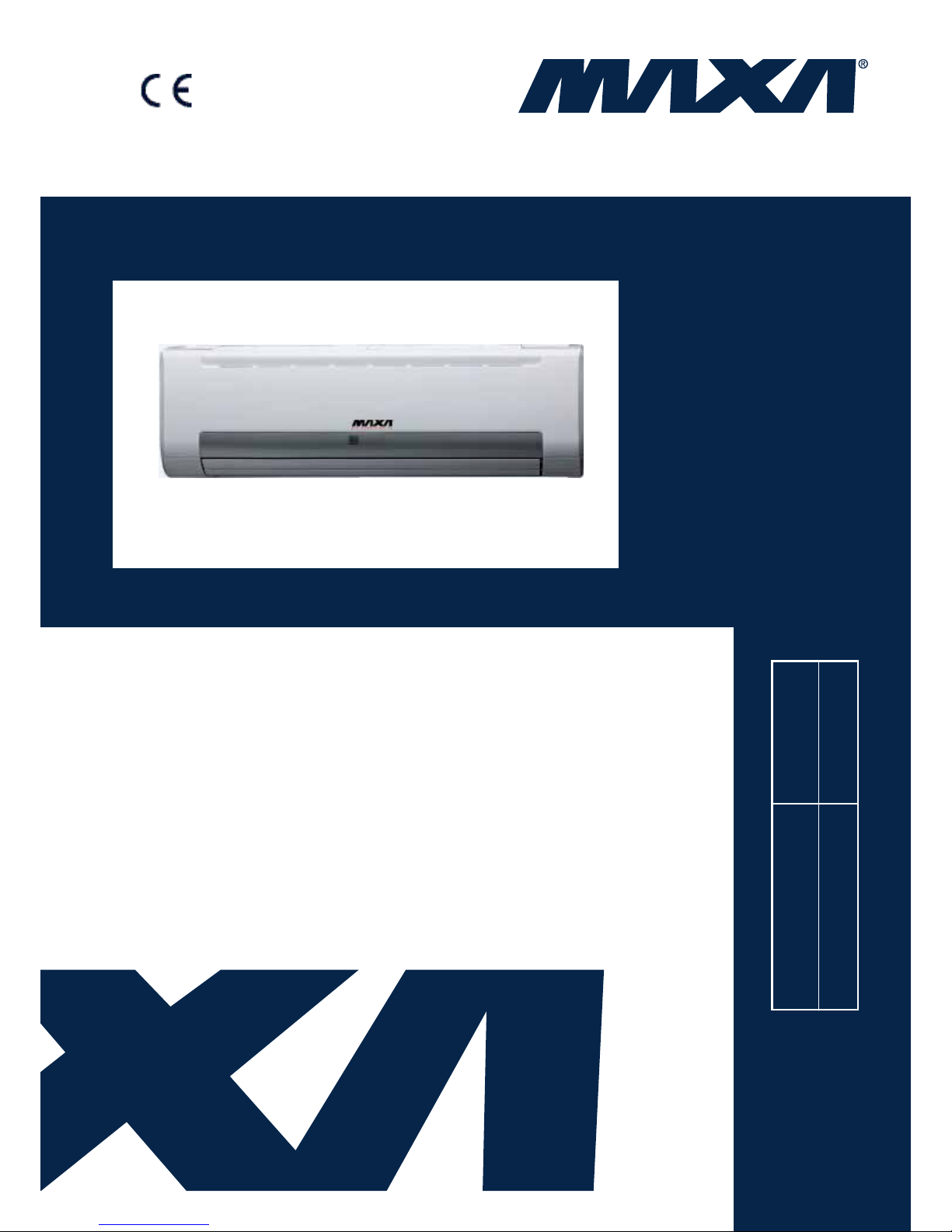
HYDRONIC HIGH WALL
D18

Hydronic Highwall
Contents
1. Introduction ......................................................................... 2
2. Nomenclature .............................................................. 2
3. Product Schedule ....................................................... 3
4. External Appearance .................................................. 3
5. Features....................................................................... 4
6. Specifications ............................................................. 5
7. Dimension ................................................................... 7
8. Service Spaces ........................................................... 7
9. Wiring Diagrams ......................................................... 8
10. Capacity Tables ........................................................ 9
11. Sound Levels .......................................................... 13
12. Exploded View ........................................................ 14
13. Installation ............................................................... 16
14. Controller ................................................................ 29
Hydronic Highwall
2 Introduction
1. Introduction
Fan coil unit is a kind of compound device which assemble fan and heat-exchang coil together. Fan coil with
fresh air supply system is a main type of center air-conditioner syste m, so it is an important compo nent of AC
devices. Fan coil unit has concealed type and exposed type. A cooling (heating) supply system usually
consists of fan coil termin als an d c hilled water system (heat ed w at er system).
Maxa fan coil is designed and manufactured on the base of advanced technology, and utilize qualified
galvanized iron as material. Due to its supper-thin design, it has such advantages: beautiful outlook, space
saving, easy installation, etc. And the most obvious advantage is that it can decrease the outlet air Tempdifference as low as possible to make room more comfortable, as well as don’t decrease cooling capacity
output. For the large air flow v olume design, it can increase r oom ventilati on frequency, supply more flesh air,
and balance room te mperature distribution. Bene fiting fro m adopt ion of adv an ced mat eria l and t echno lo gy, it
can effectively decrease t he running no ise and keep running smoothly. With the advantages above, it can be
widely applied in market, hospital, office build ing, hotel, airport, etc.
2. Nomenclature
M I – 26 A
Cooling capacity (2,6 kW)
Chilled Water Fan Coil Unit
Maxa
Hydronic Highwall
Product Schedule 3
3. Product Schedule
Model Type
Air volume
(CFM)
Power supply
MI35A
Wall mounted
250
220~240V-1Ph-50Hz MI35A 400
MI53A 500
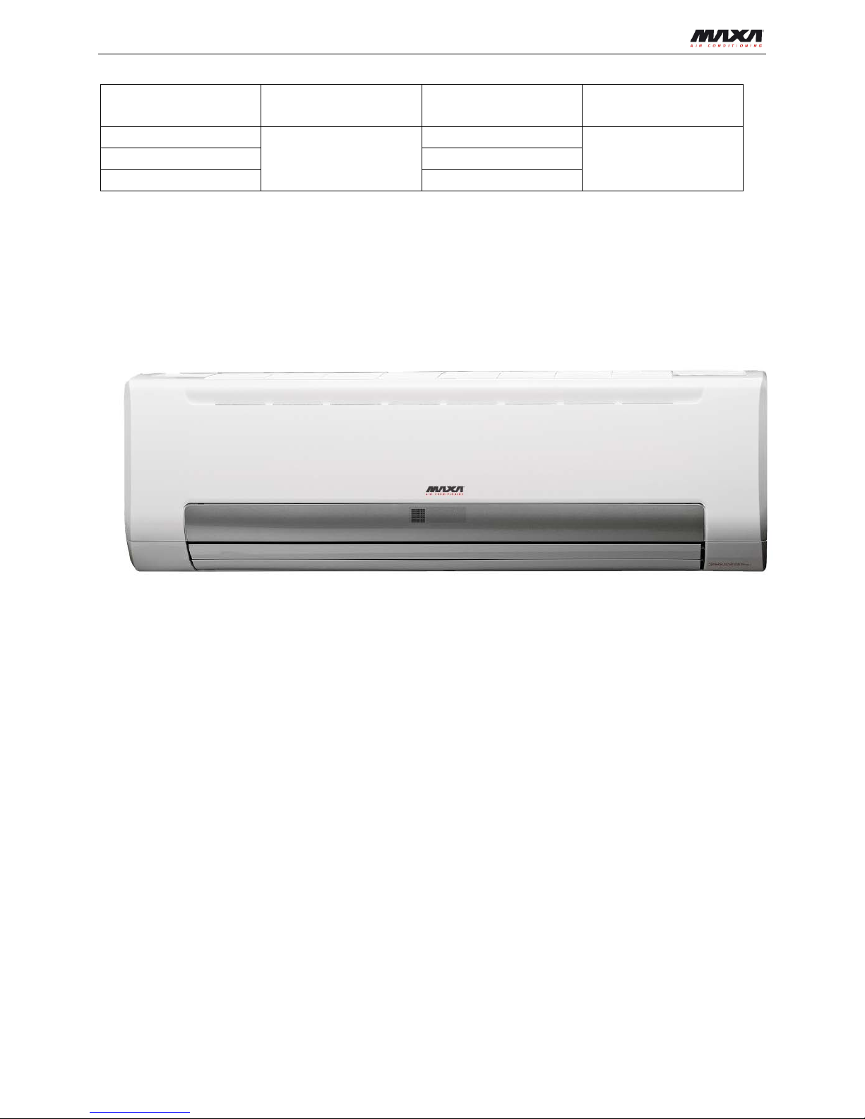
4. External Appearance
Hydronic Highwall
4 Features
5. Features
New panel supplies more choic e f or cust oms.
Multi-connection outlet pipe method: left/right/rear, more flexible for inst allation.
Wind direction adjustment can be in horizontal and vertica l way for auto swing louver
Built-in 3-way electromagnetic valve.
Easy maintenance has been r ealized as the front panel can be r emoved for easy access.
Remote controller with LCD di splay is standard, wired contr oller and central controller ar e opt ional.
Four-speed motor with super high speed reserved for mor e choice.
Right piping
Left piping
Right back piping
Left back piping
Horizontal a
ir deflector
Vertical air deflector
Hydronic Highwall
Specifications 5
6. Specifications
Model
MI26A MI35A
Air flow
H/M/L m3/h 425/360/320 680/580/510
H/M/L CFM 250/210/190 400/340/300
Cooling
Capacity H/M/L kW 2.63/2.41/2.16 3.28/2.83/2.41
Water flow rate H l/h 452 564
Water pressure drop H kPa 29.4 43.5
Heating
Capacity H/M/L kW 3.36/3.1/2.79 4.37/3.73/3.17
Water pressure drop H kPa 27.3 40.8
Power supply
V/ph/Hz
220-240/1/50
Power input
H W 24 40
Sound pressure
level H/M/L dB(A) 30/24/20 37/31/26
Fan motor
Type Low noise 4-speed fan motor
Quantity 1
Fan
Type Cross-flow fan
Quantity 1
Coil
Row 2
Max. Working pressure Mpa 1.6
Diameter mm Φ7
Body
Dimensions W×H×D mm 915×230×290
Net weight kg 13 13.3
Packing W×H×D mm 1020×315×390
Gross weight kg 16.3 16.7
Pipe
connection
Water inlet/outlet pipe Inch G3/4"
Drain pipe mm ODΦ20
Controller
R51/E (standard)
Note:
1. H: high speed; M: medium speed; L: low speed
2. Cooling Conditions: entering water 7°C, temperature rise 5°C, entering air temperat ure 27°C DB,19°CWB.
Heating Conditions: entering water 50°C, enter air temperature 20°C, the same water flow as the cooling conditions.
3. Noise is tested in semi-anechoic test room.

Hydronic Highwall
6 Specifications
Specifications
Model
MI42A
Air flow
H/M/L m3/h 850/720/640
H/M/L CFM 500/420/380
Cooling
Capacity H/M/L kW 4.25/3.85/3.32
Water flow rate H l/h 731
Water pressure drop H kPa 31.8
Heatin
g
Capacity H/M/L kW 5.81/5.17/4.43
Water pressure drop H kPa 30.2
Power supply
V/ph/Hz
220-240/1/50
Power input
H W 50
Sound pressure level
H/M/L dB(A) 39/33/28
Fan motor
Type Low noise 4-speed fan motor
Quantity 1
Fan
Type Cross-flow fan
Quantity 1
Coil
Row 2
Max. Working pressure Mpa 1.6
Diameter mm Φ7
Body
Dimensions W×H×D mm 1072×230×315
Net weight kg 15.8
Packing W×H×D mm 1180×315×415
Gross weight kg 19.4
Pipe
connection
Water inlet/outlet pipe Inch G3/4"
Drain pipe mm ODΦ20
Controller
R51/E (standard)
Note:
1. H: high speed; M: medium s peed; L: low speed
2. Cooling Conditions: entering water 7°C, temperature rise 5°C, entering air temperat ure 27°C DB,19°CWB.
Heating Conditions: entering water 50°C, enter air temperature 20°C, the same water flow as the cooling conditions.
3. Noise is tested in semi-anechoic test room.
Hydronic Highwall
Dimensioni
7
7. Dimensioni
MI26A MI35A
MI53A
Hydronic Highwall
8 Wiring Diagrams
8. Wiring Diagrams
Hydronic Highwall
Capacity Tables 9
10. Capacity Tables
Cooling Capacity:
Remark: EWT: Enter Water Temp. (℃); Δt: Temperature Difference (℃)
DB: Dry Bulb Temp. (℃); WB: Wet Bulb Temp. (℃);
TC: Total Cooling Capacity (kW); SC: Sensible Cooling Capacity (kW);
WF: Water Flow (m
3
/h); WPD: Water Pressure Drop (kPa)
MI26A
EWT Δt
Air inlet condition
DB:21 WB:15
DB:26.7 WB:19.4
DB:27 WB:19
DB:29 WB:21
DB:33 WB:25
TC
SC
WF
WPD
TC
SC
WF
WPD
TC
SC
WF
WPD
TC
SC
WF
WPD
TC
SC
WF
WPD
5
3
2.17
1.58
0.62
55.8
3.35
2.02
0.96
132.6
3.28
2.11
0.94
127.2
3.67
1.92
1.05
158.7
4.93
2.39
1.41
287.4 4 2.05
1.49
0.44
27.8
3.22
1.96
0.69
68.9
3.17
2.05
0.68
66.7
3.52
1.86
0.76
82.4
4.78
2.32
1.03
151.9 5 1.89
1.43
0.33
15.2
3.08
1.89
0.53
40.4
3.02
1.98
0.52
38.8
3.39
2.93
0.58
48.7
4.63
2.28
0.80
91.1
6
1.73
1.37
0.25
8.8
2.94
1.84
0.42
25.6
2.89
1.91
0.41
24.6
3.24
1.72
0.46
30.9
4.52
2.20
0.65
60.2
7
1.55
1.28
0.19
5.2
2.80
1.75
0.34
17.0
2.74
1.85
0.34
16.2
3.10
1.65
0.38
20.8
4.36
2.13
0.54
41.3 6 3
1.97
1.49
0.56
45.6
3.16
1.94
0.91
118.0
3.09
2.02
0.89
112.7
3.48
1.84
1.00
143.0
4.74
2.32
1.36
265.7 4 1.83
1.42
0.39
22.1
3.04
1.87
0.65
61.2
2.96
1.95
0.64
58.3
3.34
1.78
0.72
74.1
4.59
2.24
0.99
140.0
5
1.69
1.35
0.29
12.1
2.89
1.80
0.50
35.5
2.83
1.90
0.49
34.1
3.21
1.71
0.55
43.7
4.44
2.16
0.76
83.8
6
1.51
1.29
0.22
6.8
2.75
1.75
0.39
22.3
2.69
1.83
0.39
21.3
3.05
1.63
0.44
27.4
4.33
2.09
0.62
55.2 7 1.33
1.20
0.16
3.8
2.61
1.67
0.32
14.7
2.54
1.78
0.31
14.0
2.91
1.56
0.36
18.4
4.17
2.05
0.51
37.8 7 3
1.76
1.40
0.50
36.5
2.95
1.84
0.85
102.9
2.89
1.94
0.83
98.5
3.28
1.75
0.94
126.6
4.52
2.20
1.29
240.8
4
1.61
1.34
0.35
17.3
2.83
1.78
0.61
53.2
2.76
1.87
0.59
50.4
3.15
1.69
0.68
65.7
4.40
2.16
0.95
128.7
5
1.46
1.28
0.25
9.0
2.69
1.72
0.46
30.7
2.63
1.81
0.45
29.4
2.99
1.62
0.52
38.1
4.25
2.09
0.73
76.8 6 1.28
1.21
0.18
4.9
2.55
1.67
0.36
19.1
2.50
1.75
0.36
18.5
2.86
1.55
0.41
24.1
4.14
2.01
0.59
50.5 7 1.11
1.11
0.14
2.7
2.41
1.59
0.30
12.6
2.33
1.69
0.29
11.8
2.71
1.48
0.33
15.9
3.98
1.94
0.49
34.4
8
3
1.54
1.32
0.44
28.0
2.75
1.76
0.79
89.4
2.69
1.85
0.77
85.2
3.08
1.65
0.88
111.8
4.33
2.13
1.24
221.0
4
1.39
1.28
0.30
12.8
2.63
1.70
0.57
45.9
2.55
1.81
0.55
43.2
2.93
1.60
0.63
57.0
4.17
2.05
0.90
115.7 5 1.23
1.20
0.21
6.4
2.50
1.63
0.43
26.5
2.42
1.73
0.42
24.9
2.80
1.54
0.48
33.4
4.06
1.97
0.70
70.1 6 1.10
1.10
0.16
3.6
2.33
1.58
0.33
16.1
2.29
1.67
0.33
15.5
2.66
1.46
0.38
21.0
3.91
1.94
0.56
45.1
7
0.96
0.96
0.12
2.0
2.20
1.51
0.27
10.5
2.13
1.61
0.26
9.8
2.49
1.40
0.31
13.5
3.77
1.86
0.46
30.9
9
3
1.32
1.25
0.38
20.5
2.56
1.69
0.73
77.2
2.49
1.77
0.71
73.0
2.87
1.57
0.82
97.4
4.14
2.05
1.19
202.0 4 1.20
1.20
0.26
9.5
2.41
1.62
0.52
38.7
2.34
1.72
0.50
36.4
2.72
1.51
0.59
49.3
3.98
1.97
0.86
105.5 5 1.10
1.07
0.19
5.2
2.28
1.56
0.39
22.2
2.21
1.66
0.38
20.8
2.59
1.45
0.45
28.6
3.87
1.90
0.67
63.7
6
0.97
0.97
0.14
2.8
2.13
1.50
0.31
13.4
2.06
1.61
0.29
12.5
2.46
1.38
0.35
17.8
3.71
1.86
0.53
40.6
7
0.79
0.79
0.10
1.4
1.97
1.43
0.24
8.4
1.91
1.53
0.23
7.9
2.28
1.32
0.28
11.3
3.58
1.79
0.44
27.8
10
3
1.16
1.16
0.33
15.9
2.35
1.60
0.67
64.9
2.25
1.70
0.65
59.8
2.67
1.49
0.77
84.3
3.95
1.94
1.13
183.9 4 1.07
1.07
0.23
7.6
2.20
1.54
0.47
32.2
2.13
1.65
0.46
30.0
2.52
1.43
0.54
42.0
3.78
1.90
0.81
95.1
5
0.95
0.95
0.16
3.9
2.06
1.49
0.35
18.0
1.97
1.59
0.34
16.5
2.38
1.37
0.41
24.1
3.67
1.83
0.63
57.1
6
0.82
0.82
0.12
2.0
1.92
1.42
0.27
10.8
1.83
1.53
0.26
9.9
2.23
1.30
0.32
14.6
3.51
1.78
0.50
36.3 7 0.52
0.52
0.06
0.6
1.75
1.36
0.21
6.6
1.67
1.48
0.20
6.0
2.08
1.23
0.26
9.4
3.35
1.71
0.41
24.4
11
3
1.02
1.02
0.29
12.4
2.12
1.53
0.61
52.9
2.04
1.62
0.59
49.2
2.46
1.41
0.70
71.2
3.72
1.86
1.07
163.7
4
0.94
0.94
0.20
5.8
1.98
1.47
0.43
26.2
1.91
1.56
0.41
24.1
2.32
1.35
0.50
35.7
3.57
1.81
0.77
84.7
5
0.81
0.81
0.14
2.8
1.83
1.42
0.32
14.3
1.75
1.53
0.30
13.0
2.17
1.29
0.37
20.0
3.46
1.75
0.59
50.8 6 0.65
0.65
0.09
1.2
1.67
1.36
0.24
8.2
1.61
1.46
0.23
7.6
2.01
1.22
0.29
11.9
3.30
1.70
0.47
32.1 7 0.44
0.44
0.05
0.4
1.49
1.31
0.18
4.8
1.43
1.43
0.18
4.5
1.85
1.15
0.23
7.4
3.15
1.63
0.39
21.5
12
3
0.90
0.90
0.26
9.6
1.89
1.45
0.54
42.3
1.80
1.57
0.52
38.4
2.23
1.33
0.64
58.8
3.51
1.79
1.01
145.8
4
0.80
0.80
0.17
4.2
1.75
1.40
0.38
20.4
1.67
1.51
0.36
18.4
2.10
1.27
0.45
29.3
3.37
1.73
0.72
75.3 5 0.69
0.69
0.12
2.0
1.60
1.35
0.28
10.9
1.52
1.46
0.26
9.8
1.95
1.21
0.33
16.1
3.24
1.67
0.56
44.5 6 0.41
0.41
0.06
0.5
1.42
1.31
0.20
6.0
1.41
1.38
0.20
5.9
1.78
1.15
0.26
9.4
3.08
1.62
0.44
28.0
7
0.34
0.34
0.04
0.3
1.26
1.26
0.15
3.4
1.30
1.30
0.16
3.7
1.62
1.08
0.20
5.7
2.93
1.56
0.36
18.6
13
3
0.78
0.78
0.22
7.1
1.65
1.39
0.47
32.3
1.56
1.51
0.45
28.7
2.01
1.26
0.58
47.8
3.29
1.72
0.94
127.8 4 0.66
0.66
0.14
2.9
1.51
1.34
0.33
15.2
1.46
1.43
0.31
14.2
1.87
1.20
0.40
23.2
3.15
1.65
0.68
65.9 5 0.48
0.48
0.08
1.0
1.35
1.32
0.23
7.8
1.37
1.37
0.23
7.9
1.72
1.14
0.30
12.6
3.01
1.59
0.52
38.5
6
0.32
0.32
0.05
0.3
1.23
1.23
0.18
4.5
1.27
1.27
0.18
4.8
1.55
1.08
0.22
7.1
2.85
1.55
0.41
24.0
7
0.24
0.24
0.03
0.1
1.12
1.12
0.14
2.7
1.17
1.17
0.14
3.0
1.36
1.02
0.17
4.0
2.71
1.48
0.33
15.9

Hydronic Highwall
10 Capacity Tables
Cooling capacity table
MI35A
EWT Δt
Air inlet condition
DB:21 WB:15 DB:26.7 WB:19.4 DB:27 WB:19 DB:29 WB:21 DB:33 WB:25
TC SC WF WPD TC SC WF WPD TC SC WF WPD TC SC WF WPD TC SC WF WPD
5
3 2.71 1.97 0.78 82.6 4.18 2.52 1.20 196.2 4.09 2.63 1.17 188.3 4.57 2.40 1.31 234.8 6.15 2.98 1.76 425.2
4 2.55 1.86 0.55 41.1 4.02 2.44 0.86 102.0 3.95 2.55 0.85 98.7 4.39 2.32 0.94 121.9 5.96 2.89 1.28 224.7
5 2.36 1.78 0.41 22.5 3.84 2.36 0.66 59.7 3.77 2.47 0.65 57.4 4.22 3.65 0.73 72.1 5.77 2.84 0.99 134.8
6 2.15 1.70 0.31 13.0 3.67 2.29 0.53 37.9 3.60 2.39 0.52 36.4 4.04 2.15 0.58 45.8 5.63 2.75 0.81 89.1
7 1.93 1.60 0.24 7.7 3.49 2.18 0.43 25.2 3.41 2.30 0.42 24.0 3.87 2.06 0.48 30.8 5.44 2.65 0.67 61.1
6
3 2.45 1.86 0.70 67.5 3.94 2.42 1.13 174.6 3.85 2.52 1.10 166.7 4.34 2.29 1.24 211.6 5.92 2.89 1.70 393.1
4 2.28 1.77 0.49 32.7 3.79 2.33 0.81 90.6 3.70 2.44 0.79 86.3 4.17 2.22 0.90 109.6 5.73 2.79 1.23 207.2
5 2.10 1.68 0.36 17.9 3.60 2.25 0.62 52.5 3.53 2.37 0.61 50.4 4.00 2.13 0.69 64.7 5.54 2.70 0.95 124.0
6 1.89 1.61 0.27 10.0 3.43 2.18 0.49 33.1 3.35 2.28 0.48 31.5 3.80 2.04 0.54 40.6 5.40 2.60 0.77 81.7
7 1.66 1.50 0.20 5.7 3.25 2.08 0.40 21.8 3.17 2.22 0.39 20.7 3.63 1.95 0.45 27.2 5.21 2.56 0.64 55.9
7
3 2.19 1.74 0.63 53.9 3.68 2.30 1.06 152.3 3.60 2.42 1.03 145.7 4.08 2.18 1.17 187.4 5.63 2.75 1.61 356.3
4 2.01 1.68 0.43 25.6 3.53 2.22 0.76 78.8 3.44 2.34 0.74 74.6 3.92 2.11 0.84 97.3 5.49 2.70 1.18 190.4
5 1.82 1.60 0.31 13.4 3.35 2.14 0.58 45.4 3.28 2.26 0.56 43.5 3.73 2.02 0.64 56.4 5.30 2.60 0.91 113.6
6 1.60 1.51 0.23 7.2 3.18 2.08 0.46 28.3 3.12 2.18 0.45 27.3 3.56 1.93 0.51 35.7 5.16 2.51 0.74 74.7
7 1.39 1.39 0.17 4.0 3.01 1.98 0.37 18.6 2.91 2.11 0.36 17.4 3.37 1.85 0.41 23.5 4.97 2.41 0.61 51.0
8
3 1.92 1.65 0.55 41.5 3.43 2.20 0.98 132.3 3.35 2.30 0.96 126.1 3.84 2.06 1.10 165.5 5.40 2.65 1.55 327.0
4 1.73 1.60 0.37 19.0 3.28 2.13 0.71 68.0 3.18 2.25 0.68 63.9 3.65 2.00 0.79 84.3 5.21 2.56 1.12 171.2
5 1.53 1.50 0.26 9.5 3.11 2.04 0.54 39.2 3.02 2.16 0.52 36.9 3.50 1.92 0.60 49.5 5.06 2.46 0.87 103.7
6 1.38 1.38 0.20 5.3 2.91 1.97 0.42 23.8 2.85 2.08 0.41 22.9 3.32 1.83 0.48 31.0 4.88 2.41 0.70 66.7
7 1.20 1.20 0.15 3.0 2.74 1.88 0.34 15.5 2.66 2.01 0.33 14.5 3.11 1.75 0.38 19.9 4.70 2.32 0.58 45.7
9
3 1.64 1.56 0.47 30.3 3.19 2.10 0.91 114.3 3.10 2.21 0.89 107.9 3.58 1.96 1.03 144.2 5.16 2.56 1.48 298.9
4 1.49 1.49 0.32 14.0 3.01 2.03 0.65 57.2 2.92 2.14 0.63 53.9 3.40 1.89 0.73 73.0 4.97 2.46 1.07 156.0
5
1.38
1.33
0.24
7.7
2.85
1.94
0.49
32.8
2.76
2.07
0.47
30.8
3.23
1.80
0.56
42.3
4.83
2.37
0.83
94.2
6 1.21 1.21 0.17 4.1 2.66 1.87 0.38 19.9 2.57 2.00 0.37 18.5 3.06 1.72 0.44 26.3 4.62 2.31 0.66 60.0
7 0.98 0.98 0.12 2.0 2.46 1.78 0.30 12.5 2.38 1.91 0.29 11.6 2.85 1.64 0.35 16.7 4.47 2.23 0.55 41.2
10
3 1.45 1.45 0.42 23.6 2.93 1.99 0.84 96.1 2.81 2.13 0.80 88.5 3.33 1.86 0.96 124.7 4.92 2.41 1.41 272.1
4 1.33 1.33 0.29 11.2 2.75 1.92 0.59 47.6 2.65 2.05 0.57 44.4 3.14 1.78 0.67 62.2 4.72 2.37 1.01 140.7
5 1.19 1.19 0.20 5.7 2.57 1.86 0.44 26.6 2.46 1.99 0.42 24.4 2.97 1.70 0.51 35.7 4.57 2.28 0.79 84.5
6 1.02 1.02 0.15 2.9 2.39 1.77 0.34 16.0 2.28 1.91 0.33 14.6 2.78 1.62 0.40 21.7 4.37 2.22 0.63 53.7
7 0.65 0.65 0.08 0.9 2.18 1.70 0.27 9.8 2.08 1.84 0.26 8.9 2.60 1.54 0.32 13.9 4.18 2.13 0.51 36.0
11
3 1.28 1.28 0.37 18.3 2.64 1.90 0.76 78.3 2.55 2.03 0.73 72.8 3.06 1.76 0.88 105.3 4.64 2.32 1.33 242.1
4 1.17 1.17 0.25 8.6 2.48 1.84 0.53 38.7 2.38 1.95 0.51 35.7 2.89 1.68 0.62 52.8 4.45 2.26 0.96 125.3
5 1.01 1.01 0.17 4.1 2.29 1.77 0.39 21.1 2.18 1.90 0.38 19.2 2.70 1.60 0.46 29.5 4.31 2.18 0.74 75.2
6 0.80 0.80 0.12 1.8 2.08 1.69 0.30 12.2 2.00 1.82 0.29 11.3 2.51 1.52 0.36 17.7 4.11 2.13 0.59 47.5
7 0.54 0.54 0.07 0.6 1.86 1.63 0.23 7.1 1.79 1.79 0.22 6.6 2.31 1.43 0.28 11.0 3.92 2.04 0.48 31.8
12
3 1.13 1.13 0.32 14.3 2.36 1.81 0.68 62.7 2.25 1.95 0.64 56.8 2.78 1.66 0.80 87.0 4.38 2.23 1.26 215.7
4 0.99 0.99 0.21 6.2 2.19 1.75 0.47 30.2 2.08 1.89 0.45 27.3 2.62 1.59 0.56 43.3 4.20 2.16 0.90 111.3
5
0.86
0.86
0.15
3.0
2.00
1.69
0.34
16.1
1.89
1.83
0.33
14.5
2.43
1.51
0.42
23.8
4.04
2.08
0.69
65.9
6 0.52 0.52 0.07 0.7 1.77 1.63 0.25 8.8 1.76 1.72 0.25 8.7 2.22 1.43 0.32 13.9 3.84 2.03 0.55 41.5
7 0.43 0.43 0.05 0.4 1.57 1.57 0.19 5.1 1.62 1.62 0.20 5.4 2.02 1.34 0.25 8.4 3.65 1.95 0.45 27.5
13
3 0.97 0.97 0.28 10.6 2.06 1.73 0.59 47.8 1.95 1.88 0.56 42.5 2.51 1.57 0.72 70.7 4.10 2.14 1.18 189.1
4 0.83 0.83 0.18 4.3 1.89 1.67 0.41 22.5 1.82 1.79 0.39 21.0 2.33 1.49 0.50 34.3 3.93 2.06 0.84 97.5
5 0.60 0.60 0.10 1.4 1.68 1.65 0.29 11.5 1.70 1.70 0.29 11.7 2.14 1.42 0.37 18.6 3.75 1.98 0.65 57.0
6 0.40 0.40 0.06 0.4 1.53 1.53 0.22 6.6 1.59 1.59 0.23 7.1 1.94 1.34 0.28 10.5 3.56 1.93 0.51 35.6
7 0.29 0.29 0.04 0.2 1.40 1.40 0.17 4.0 1.46 1.46 0.18 4.4 1.69 1.27 0.21 5.9 3.37 1.85 0.41 23.5
Hydronic Highwall
Capacity Tables 11
Cooling capacity table
MI53A
EWT Δt
Air inlet condition
DB:21 WB:15 DB:26.7 WB:19.4 DB:27 WB:19 DB:29 WB:21 DB:33 WB:25
TC SC WF WPD TC SC WF WPD TC SC WF WPD TC SC WF WPD TC SC WF WPD
5
3 3.51 2.55 1.01 60.4 5.42 3.26 1.55 143.4 5.30 3.40 1.52 137.6 5.92 3.11 1.70 171.6 7.97 3.86 2.29 310.8
4 3.31 2.41 0.71 30.1 5.21 3.16 1.12 74.6 5.12 3.31 1.10 72.1 5.69 3.01 1.22 89.1 7.73 3.74 1.66 164.3
5 3.05 2.31 0.53 16.4 4.98 3.05 0.86 43.7 4.88 3.20 0.84 42.0 5.47 4.73 0.94 52.7 7.48 3.68 1.29 98.6
6 2.79 2.21 0.40 9.5 4.76 2.97 0.68 27.7 4.67 3.09 0.67 26.6 5.23 2.78 0.75 33.5 7.30 3.56 1.05 65.1
7 2.50 2.07 0.31 5.6 4.53 2.83 0.56 18.4 4.42 2.99 0.54 17.6 5.01 2.67 0.62 22.6 7.05 3.43 0.87 44.7
6
3 3.18 2.40 0.91 49.4 5.11 3.13 1.46 127.6 4.99 3.27 1.43 121.9 5.62 2.97 1.61 154.7 7.67 3.74 2.20 287.4
4 2.95 2.29 0.63 23.9 4.91 3.02 1.05 66.2 4.79 3.16 1.03 63.1 5.40 2.87 1.16 80.1 7.42 3.62 1.60 151.5
5 2.72 2.18 0.47 13.1 4.67 2.91 0.80 38.3 4.58 3.07 0.79 36.9 5.18 2.76 0.89 47.3 7.18 3.50 1.23 90.6
6 2.45 2.09 0.35 7.3 4.45 2.83 0.64 24.2 4.34 2.95 0.62 23.0 4.92 2.64 0.71 29.7 6.99 3.37 1.00 59.8
7 2.15 1.94 0.26 4.2 4.21 2.70 0.52 15.9 4.11 2.87 0.50 15.2 4.70 2.53 0.58 19.9 6.75 3.31 0.83 40.9
7
3 2.84 2.26 0.81 39.4 4.77 2.98 1.37 111.3 4.67 3.13 1.34 106.5 5.29 2.82 1.52 137.0 7.30 3.56 2.09 260.5
4 2.61 2.17 0.56 18.7 4.58 2.88 0.98 57.6 4.45 3.03 0.96 54.5 5.08 2.73 1.09 71.1 7.11 3.50 1.53 139.2
5 2.35 2.07 0.41 9.8 4.34 2.77 0.75 33.2 4.25 2.93 0.73 31.8 4.84 2.62 0.83 41.2 6.87 3.37 1.18 83.1
6 2.07 1.96 0.30 5.3 4.12 2.69 0.59 20.7 4.04 2.82 0.58 20.0 4.62 2.50 0.66 26.1 6.68 3.25 0.96 54.6
7 1.80 1.80 0.22 2.9 3.89 2.57 0.48 13.6 3.77 2.74 0.46 12.7 4.37 2.40 0.54 17.2 6.44 3.13 0.79 37.2
8
3 2.49 2.14 0.71 30.3 4.45 2.85 1.27 96.7 4.34 2.99 1.24 92.2 4.97 2.67 1.43 121.0 6.99 3.43 2.00 239.0
4 2.24 2.07 0.48 13.9 4.25 2.75 0.91 49.7 4.12 2.92 0.89 46.7 4.73 2.59 1.02 61.7 6.75 3.31 1.45 125.2
5 1.99 1.94 0.34 7.0 4.04 2.64 0.69 28.7 3.91 2.80 0.67 27.0 4.53 2.48 0.78 36.2 6.56 3.19 1.13 75.8
6 1.78 1.78 0.26 3.9 3.77 2.56 0.54 17.4 3.70 2.70 0.53 16.7 4.31 2.37 0.62 22.7 6.32 3.13 0.91 48.8
7 1.56 1.56 0.19 2.2 3.55 2.44 0.44 11.3 3.44 2.61 0.42 10.6 4.03 2.27 0.50 14.6 6.10 3.01 0.75 33.4
9
3 2.13 2.02 0.61 22.1 4.13 2.72 1.18 83.6 4.02 2.86 1.15 78.9 4.64 2.54 1.33 105.4 6.68 3.31 1.92 218.5
4 1.93 1.93 0.42 10.3 3.90 2.62 0.84 41.8 3.78 2.77 0.81 39.4 4.40 2.45 0.95 53.3 6.44 3.19 1.38 114.1
5
1.78
1.73
0.31
5.6
3.69
2.51
0.64
24.0
3.58
2.68
0.61
22.5
4.19
2.34
0.72
30.9
6.26
3.07
1.08
68.9
6 1.56 1.56 0.22 3.0 3.45 2.42 0.49 14.5 3.32 2.59 0.48 13.5 3.97 2.23 0.57 19.2 5.99 3.00 0.86 43.9
7 1.28 1.28 0.16 1.5 3.19 2.31 0.39 9.1 3.08 2.48 0.38 8.5 3.69 2.13 0.45 12.2 5.79 2.89 0.71 30.1
10
3 1.88 1.88 0.54 17.2 3.79 2.58 1.09 70.2 3.64 2.75 1.04 64.7 4.32 2.40 1.24 91.2 6.38 3.13 1.83 198.9
4 1.72 1.72 0.37 8.2 3.56 2.48 0.76 34.8 3.43 2.66 0.74 32.4 4.07 2.31 0.87 45.5 6.11 3.07 1.31 102.8
5 1.54 1.54 0.26 4.2 3.32 2.40 0.57 19.5 3.18 2.58 0.55 17.8 3.85 2.21 0.66 26.1 5.92 2.96 1.02 61.8
6 1.32 1.32 0.19 2.1 3.10 2.30 0.44 11.7 2.96 2.48 0.42 10.7 3.60 2.10 0.52 15.8 5.67 2.88 0.81 39.3
7 0.84 0.84 0.10 0.6 2.83 2.20 0.35 7.2 2.69 2.39 0.33 6.5 3.37 1.99 0.41 10.2 5.42 2.76 0.67 26.3
11
3 1.66 1.66 0.47 13.4 3.42 2.47 0.98 57.3 3.30 2.62 0.95 53.2 3.97 2.28 1.14 77.0 6.02 3.01 1.72 177.0
4 1.51 1.51 0.33 6.3 3.21 2.38 0.69 28.3 3.08 2.53 0.66 26.1 3.75 2.18 0.81 38.6 5.77 2.93 1.24 91.6
5 1.31 1.31 0.23 3.0 2.96 2.29 0.51 15.4 2.83 2.47 0.49 14.1 3.50 2.08 0.60 21.6 5.59 2.83 0.96 55.0
6 1.04 1.04 0.15 1.3 2.70 2.20 0.39 8.9 2.59 2.35 0.37 8.2 3.25 1.97 0.47 12.9 5.33 2.75 0.76 34.7
7 0.71 0.71 0.09 0.4 2.40 2.12 0.30 5.2 2.32 2.32 0.28 4.8 2.99 1.86 0.37 8.0 5.08 2.64 0.62 23.2
12
3 1.46 1.46 0.42 10.4 3.06 2.35 0.88 45.8 2.91 2.53 0.84 41.5 3.61 2.15 1.03 63.6 5.68 2.89 1.63 157.7
4 1.29 1.29 0.28 4.6 2.83 2.27 0.61 22.1 2.69 2.45 0.58 19.9 3.39 2.05 0.73 31.6 5.44 2.80 1.17 81.4
5
1.11
1.11
0.19
2.2
2.59
2.19
0.45
11.8
2.45
2.37
0.42
10.6
3.15
1.96
0.54
17.4
5.23
2.70
0.90
48.2
6 0.67 0.67 0.10 0.5 2.30 2.12 0.33 6.5 2.28 2.23 0.33 6.3 2.88 1.85 0.41 10.2 4.98 2.62 0.71 30.3
7 0.55 0.55 0.07 0.3 2.04 2.04 0.25 3.7 2.10 2.10 0.26 4.0 2.62 1.74 0.32 6.2 4.73 2.52 0.58 20.1
13
3 1.26 1.26 0.36 7.7 2.67 2.24 0.77 35.0 2.52 2.43 0.72 31.1 3.25 2.03 0.93 51.7 5.32 2.78 1.52 138.3
4 1.07 1.07 0.23 3.2 2.45 2.16 0.53 16.5 2.36 2.32 0.51 15.3 3.02 1.93 0.65 25.0 5.09 2.67 1.09 71.3
5 0.77 0.77 0.13 1.1 2.18 2.13 0.38 8.4 2.21 2.21 0.38 8.6 2.78 1.84 0.48 13.6 4.86 2.57 0.84 41.6
6 0.52 0.52 0.07 0.3 1.99 1.99 0.28 4.8 2.05 2.05 0.29 5.2 2.51 1.74 0.36 7.7 4.61 2.50 0.66 26.0
7 0.38 0.38 0.05 0.1 1.82 1.82 0.22 3.0 1.89 1.89 0.23 3.2 2.20 1.64 0.27 4.3 4.37 2.40 0.54 17.2

Hydronic Highwall
12 Capacity Tables
Cooling capacity modification coefficient table:
Speed
MI26A
MI35A
MI42A
TC SC TC SC TC SC
High 1 1 1 1 1 1
Mid
0.92
0.9
0.86
0.83
0.91
0.86
Low
0.82
0.8
0.73
0.7
0.78
0.75
Heating Capacity:
Remark:
Δt: Temperature Difference (℃) ; TH: Total Heating Capacity (kW);
WF: Water Flow (m
3
/h); WPD: Water Pressure Drop (kPa)
MI26A
Δt
Air inlet temp. (20℃ DB)
Water in let temp. (℃)
35 40 45 50 55 60 65 70
TH WF WPD TH WF WPD TH WF WPD TH WF WPD TH WF WPD TH WF WPD TH WF WPD TH WF WPD
10
1.15
0.10
1.2 1.80
0.15
2.8 2.49
0.21
5.4 3.14
0.27
8.7 3.80
0.33
12.6 4.46
0.38
17.5 5.11
0.44
22.9 5.75
0.49
29.0
8
1.27
0.14
2.2 1.98
0.21
5.4 2.65
0.28
9.6 3.31
0.36
15.0 3.94
0.42
21.3 4.58
0.49
28.8 5.23
0.56
37.4 5.87
0.63
47.2
6
1.47
0.21
5.3 2.14
0.31
11.2 2.78
0.40
18.8 3.45
0.49
29.0 4.10
0.59
41.0 4.74
0.68
54.9 5.35
0.77
69.7 6.03
0.86
88.6
MI35A
Δt
Air inlet temp. (20℃ DB)
Water in let temp. (℃)
35 40 45 50 55 60 65 70
TH WF WPD TH WF WPD TH WF WPD TH WF WPD TH WF WPD TH WF WPD TH WF WPD TH WF WPD
10
1.49
0.13
2.1 2.34
0.20
5.1 3.25
0.28
9.7 4.10
0.35
15.5 4.95
0.43
22.7 5.82
0.50
31.3 6.66
0.57
41.0 7.50
0.65
52.0
8
1.66
0.18
4.0 2.58
0.28
9.6 3.46
0.37
17.3 4.31
0.46
26.8 5.14
0.55
38.2 5.98
0.64
51.6 6.82
0.73
67.1 7.66
0.82
84.7
6
1.92
0.28
9.5 2.80
0.40
20.1 3.62
0.52
33.7 4.50
0.65
52.0 5.35
0.77
73.5 6.19
0.89
98.4 6.98
1.00
124.9 7.87
1.13
158.9
MI42A
Δt
Air inlet temp. (20℃ DB)
Water in let temp. (℃)
35 40 45 50 55 60 65 70
TH WF WPD TH WF WPD TH WF WPD TH WF WPD TH WF WPD TH WF WPD TH WF WPD TH WF WPD
10
1.99
0.17
1.6 3.13
0.27
3.9 4.33
0.37
7.5 5.46
0.47
11.9 6.60
0.57
17.4 7.76
0.67
24.1 8.88
0.76
31.5
10.00
0.86
40.0
8
2.21
0.24
3.1 3.44
0.37
7.4 4.61
0.50
13.3 5.75
0.62
20.7 6.85
0.74
29.4 7.97
0.86
39.7 9.09
0.98
51.7
10.21
1.10
65.1
6
2.56
0.37
7.3 3.73
0.53
15.4 4.83
0.69
25.9 6.00
0.86
40.0 7.13
1.02
56.5 8.25
1.18
75.7 9.30
1.33
96.1
10.49
1.50
122.3
Heating capacity modification coefficient table :
Speed
MI26A
MI35A
MI42A
TH TH TH
High 1 1
1
Mid
0.92
0.85
0.89
Low
0.83
0.73
0.76

Hydronic Highwall
Sound Levels 13
Altitude modification coefficient table:
Altitude (m)
TC
SC
TH
500
0.98
0.95
0.95
1000
0.97
0.91
0.91
1500
0.95
0.86
0.86
2000
0.94
0.82
0.82
2500
0.93
0.78
0.78
3000
0.91
0.74
0.7
11. Sound Levels
Test condition
Unit Number Model
Sound pressure level under three speeds of fan (dB(A))
H M L
1 MI26A 30 24 20
3 MI35A 37 31 26
4 MI53A 39 33 28

Hydronic Highwall
14 Ex ploded V iew
12. Exploded View
MI26A MI35A
No. Part Name Quantity
No. Part Name Quantity
1 Filter 2 14 Louver 1
2 Evaporator I 1 15 Panel dalle 1
3 Evaporator II 1 16 Panel 1
4 Evaporator Ⅲ 1 17 Panel frame ass'y 1
5 Coil temp sensor 1 18 Stepper motor 2
6 Evaporate connect board 1 19 Screw cover 3
7 Display board ass'y 1 20 Pipe clamp 1
8 Motor 1 21 Drainage pan 1
9 Base pan assembly 1 22 Bearing base 1
10 Motor spud 2 23 Evaporator left clapboard 1
11 E-part box ass'y 1 24 W ater inlet pip e ass'y 1
11.1 Dial code switch box cover 1 25 Water outlet pipe ass'y 1
11.2 Electric control box seat 1 26 Three-way valve 1
11.3 E-Part box cover 1 27 Control wire for 3-Ways valve 1
11.4 Electric control box soleplate 1 28 Outlet screw pipe ass'y 1
11.5 Electric control box side board ass'y 1 29 Inlet screw pipe ass'y 1
11.6 Dial code switch board ass'y 1 30 Discharge valve 1
11.7 Main controller ass'y 1 31 Cross fan 1
11.8 Transformer 1 32 Base pan holder 1
11.9 Wire joint 1 33 Formaldehyde killer 1
11.10 Wire joint, 3p 1 34 Room Temperature Sensor Ass'y 1
11.11 Motor capacitor 1 35 Network matching wire 1
12 Air outlet frame mount ass'y 1 36 Remote controller 1
13 Louver board 1 37 Remote controller holder ass'y 1

Hydronic Highwall
Exploded View 15
MI53A
No. Part Name Quantity
No. Part Name Quantity
1 Filter 2 14 Air outlet frame mount ass'y 1
2 Evaporator I 1 15 Louver board 1
3 Evaporator II 1 16 Louver 1
4 Evaporator Ⅲ 1 17 Panel dalle 1
5 Coil temp sensor 1 18 Panel 1
6 Evaporate connect board 1 19 Stepper motor 2
7 Cross fan 1 20 Screw cover 3
8 Display board ass'y 1 21 Pipe clamp 1
9 Motor 1 22 Drainage pan 1
10 Base pan assembly 1 23 Bearing base 1
11 Motor spud 2 24 Water inlet pipe ass'y 1
12 Panel frame ass'y 1 25 Water outlet pip e ass'y 1
13 E-part box ass'y 1 26 Three-way valve 1
13.1 Dial code switch box cover 1 27 Control wire for 3-Ways valve 1
13.2 Electric control box seat 1 28 Outlet screw pipe ass'y 1
13.3 E-Part box cover 1 29 Inlet screw pipe ass'y 1
13.4 Electric control box soleplate 1 30 Discharge valve 1
13.5 Electric control box side board ass'y
1 31 Evaporator left clapboard 1
13.6 Dial code switch board ass'y 1 32 Base pan holder 1
13.7 Main controller ass'y 1 33 Formaldehyde killer 1
13.8 Transformer 1 34 Room Temperature Sensor Ass'y
1
13.9 Motor capacitor 1 35 Network matching wire 1
13.10 Wire joint, 3p 1 36 Remote controller 1
13.11 Wire joint 1 37 Remote controller holder ass'y 1

Hydronic Highwall
16 Installation
13. Installation
13.1 Precautions
Be sure to be in conformity with the local, national and international laws and regulations.
Read "PRECAUTIONS" c ar ef ul ly before installation.
The following precautions include important safty it ems. O bserve them and never forget.
Keep the installation manual in a handy place for future refere nce.
Before out from factory, FAN COIL UNIT ( AIR UNITS) has passed Fan Co il Overpressure Resi stant Test,
Statically and Dynamically Balanced Adjustment, Noise Test, Air (cool) Volume Test, Electric Property
Test, Outline Quality Detection.
The safety precautions listed here are divided into two categories. In either case, important safety
information is listed which mu st be r ead carefully.
Warning: Failure to observe a warning may result in death.
Caution: Failure to observe a caution may resu lt in injury or damage to the equipment.
After completing the installation, make sure that the unit operates properly during the start-up operation.
Please instruct the custo mer on how to operate the unit and keep it maintained.
Warning:
Be sure only trained and qualified service personnel to install, repair or service the equipment.
Improper installation, repair, and maintenance may result in electric shocks, short-circuit, leaks, fire or
other damage to the equipme nt .
Install according to the installation instructions strictly.
If installation is defective, it will cause water leakage, electrical shock and fire.
When installing the unit in a small room, take measures against to keep refrigerant concentration
from exceeding allowable safety limits in the event of refrigerant leakage.
Contact the place of purchase for more information. Excessive refrigerant in a closed ambient can lead
to oxygen deficiency.
Use the attached accessories parts and specified parts for installation.
Otherwise, it will cause the s et t o fall, w at er leakage, electrical shock and fire.
The appliance must be installed 2.3m above floor.
The appliance shall not be installed in the laundry.
Before obtaining access to terminals, all supply circuits must be disconnected.
The appliance must be positioned so that the plug is accessible.
The enclosure of the appliance shall be marked by word, or by symbols, with the direction of the
fluid flow.
For electrical work, follow the local national wiring standard, regulation the installation
instructions. An independent circuit and single outlet must be used.
If electrical circuit capacity is not enough or defect in electr i cal w ork, it will cause electrical shock fire.
Use the specified cable and connect tightly and clamp the cable so that no external force will be
acted on the terminal.
If connection or fixing is not per fe ct , it will cause heat-up or fire at t he connection.
Wiring routing must be properly arranged so that control board cover is fixed properly.
If control board cover is not fixed perfectly, it will cause heat-up at connection point of terminal, fire or
electrical shock.
If the supply cord is damaged, it must be replaced by the manufacture or its service agent or a
similarly qualified person in order to avoid a hazard.
An all-pole disconnection switch having a contact separation of at least 3mm in all poles should
be connected in fixed wiring.

Hydronic Highwall
Installation 17
When carrying out piping connection, take care not to let air substances go into refrigeration
cycle.
Otherwise, it will cause lower capacity, abnormal high pr essure in the refrigeration cy cl e.
Do not modify the length of the power supply cord or use of extension cord, and do not share
the single outlet with other electrical appliances.
Otherwise, it will cause fire or electrical shock.
If the water leaks during installation, ventilate the area immediately.
After completing the installation work, check that the water does not leak.
The cool water in the unit is not lower than 3 ℃, hot wat er is not higher than 70℃. Water in the unit must
clean, air quality must meet t o the standard of PH=6.5~7.5.
Caution:
Ground the air conditioner.
Do not connect the ground wire to gas or wat er pipes , lightnin g rod or te lephone gr ound wire.I ncompl ete
grounding may result in elect r ic shocks.
Be sure to install an earth leakage breaker.
Failure to install an earth lea kage br eaker may result in electric shocks.
Connect the outdoor unit wires, and then connect the indoor unit wires.
You are not allowed to connect the air conditioner with the power source until wiring and piping the air
conditioner is done.
While following the installation instructions, install drain piping in order to ensure proper
drainage and insulate piping in order to prevent condensation.
Improper drain piping may result in water leakage and property damage.
Install the indoor and outdoor units, power supply wiring and connecting wires at least 1 meter
away from televisions or radios in order to prevent image interference or noise.
Depending on the radio w aves, a distance of 1 meter may not b e sufficient enough to elimin ate the noise.
This appliance is not intended for use by persons (including children) with reduced
physical,sensory or mental capabilities, or lack of experience and knowledge, unless they have
been given supervision or instruction concerning use of the appliance by a person responsible
for their safety.
Don't install the air conditioner in the following locations:
There is petrolatum existing.
There is salty air surrounding (ne ar the coast).
There is caustic gas (the sul fid e, for example) existing in t he air (near a hot spring).
The Volt vibrates violently (in the factor ies).
In buses or cabinets.
In kitchen where it is full of oil gas.
There is strong electroma gnet ic w ave existing.
There are inflammable ma terials or gas.
There is acid or alkaline liqui d evaporating.
Other special conditions.

Hydronic Highwall
18 Installation
13.2 Accessory
Name Shape Quantity Function
1. Screw ST3.9x25 for installation board
3 Secure the installation board
2. Plastic expanded tube
3
3. Wrapping tape
1
4. Drain pipe
1
5. Wall conduit cover
1
6. Remote controller
(including operation manual)
1
7. Frame
1 Hold the remote controller
8. Mounting screw (ST2.9 x 10-C-H)
2 Insulation the holder of remote controller
9. Alkaline dry batteries (AM4)
2
10. Owner's manual
1
11. Installation manual
1
12. seel gasket
4 For connecting water pipe
13.3 Remote controller installation
Never throw or beat the contr oller.
Before installation, operate the remote controller t o det ermine its location in a recept i on r ange.
Keep the remote controller at least 1m apart fro m the nearest TV set or ster eoequipment. ( it is necessary
to prevent image disturba nc es or noise interferences.)
Do not install the remote controller in a place exposed to direct sunlight or close to a heating source,
such as a stove.
Note that the positive and negative poles are right positions whe n loading batteries.
This information is subject to change s due t o technological improv em ent without further notices.

Hydronic Highwall
Installation 19
13.4 Indoor unit installation
13.4.1 Installation place
Installation in t he followi ng places may c ause trouble . If it is unavoidable, please consult with t he local de aler.
A place f ul l of m achine oil.
A salin e pla c e such as coast.
A place f ul l of s ul fide gas such as hot-spring r esor t .
Places where there are high frequency machines such as wireless equipment, welding machine, and
medical facility.
A place t her e i s no c ombustive gases and volati le matter.
A place of special environmental conditions.
Indoor unit installation place
A place w her e is no obstacle near the inlet and outlet area.
A place w hi c h can bear the indoor unit.
A place w hi c h is c onvenient to maintenance.
A place w hi c h pr ovides the space around the indoor unit as required r ight i n t he diagram.
There is strong electroma gnet ic w ave existing.
A place w hi c h is far from heat, steam and infla m mable gas.
13.4.2 Drilling a hole and mounting installation board
Installation Board and Its Direction (unit: mm)
MI26A/MI35A type MI42A type
Fix the installation board.
Install the installation board horizontally on structural parts on the wall with the spaces provided around
the plate.
In case of brick, concrete or similar type walls, make 5mm dia. holes on the wall. Insert clip anchors for
Remote
controller
CANCEL
LOCK
SET TEMPERATURE(°C)
AUTO
COOL
DRY
HEAT
FAN
HIGH
MED
LOW
TE M P
MODE
SWING TIMER
RESET
ON/OFF
FAN
SPEED
VENT
ECO NO MI C
RUN NI NG
Remote controller
holder
Mounting screw B
ST2.9x10-C-H
460
25
290
915
mounting board of indoor unit
the shape of indoor unit
730
316
1070
36
mounting board of indoor unit
the shape of indoor unit

Hydronic Highwall
20 Installation
appropriate mounting screws.
Fix the installation board on t he w all.
Right installation
False installation
Drilling a hole
Determine the pipe hole position using t he instal lation board, and drill th e pipe hole (N95mm) s o it slants
slightly downward.
Always use a wall hole condu it w hen piercing metal lath, ply w ood or metal plate.
13.4.3 Connective and drain pipe installation
Drain pipe installation
Run the drain hose sloping dow nward. Do not install the dr ai n hose as illustrated below.
When connection extended drain hose, i nsulate the connecting par t of extended drain hose with a shield
pipe.
Connection pipe installation
mounting
board
of indoor unit
horizontal line
Tow Screw
Tow Screw
mounting
board
ofindoorunit
horizontal line
mounting
board
of indoor unit
horizontal line
Do not form a rise
Do not put the hose
end into water
Shield pipe
Wall
Drain hose
Extended drain hose

Hydronic Highwall
Installation 21
For the left-hand and rear-left-hand piping, install the piping as shown. Bend the connective pipe to be
laid at 43mm height or less from the wall.
Fix the end of the connectiv e pipe. (Re fer to Tightening Connection in WATER PIPING INST ALLATION)
Cautions:
Connect the indoor unit first, then the outdoor unit. Bend and arrange t he pipe carefully.
Do not allow the piping to let out fro m the back of the indoor unit .
Be careful not to let the drain hose slack.
Insulate both of the auxiliary piping.
Banding the drain hose under t he auxiliary pipe.
Piping and bandaging
Wind the connective cable, drain hose and wiring with tape securely, evenly as shown below.
Because the condensed water from rear of the indoor unit is gathered in Pond Box and is piped out of
room. Do not put anything else in the box.
13.4.4 Indoor unit installation
Pass the piping through the hol e in the w all.
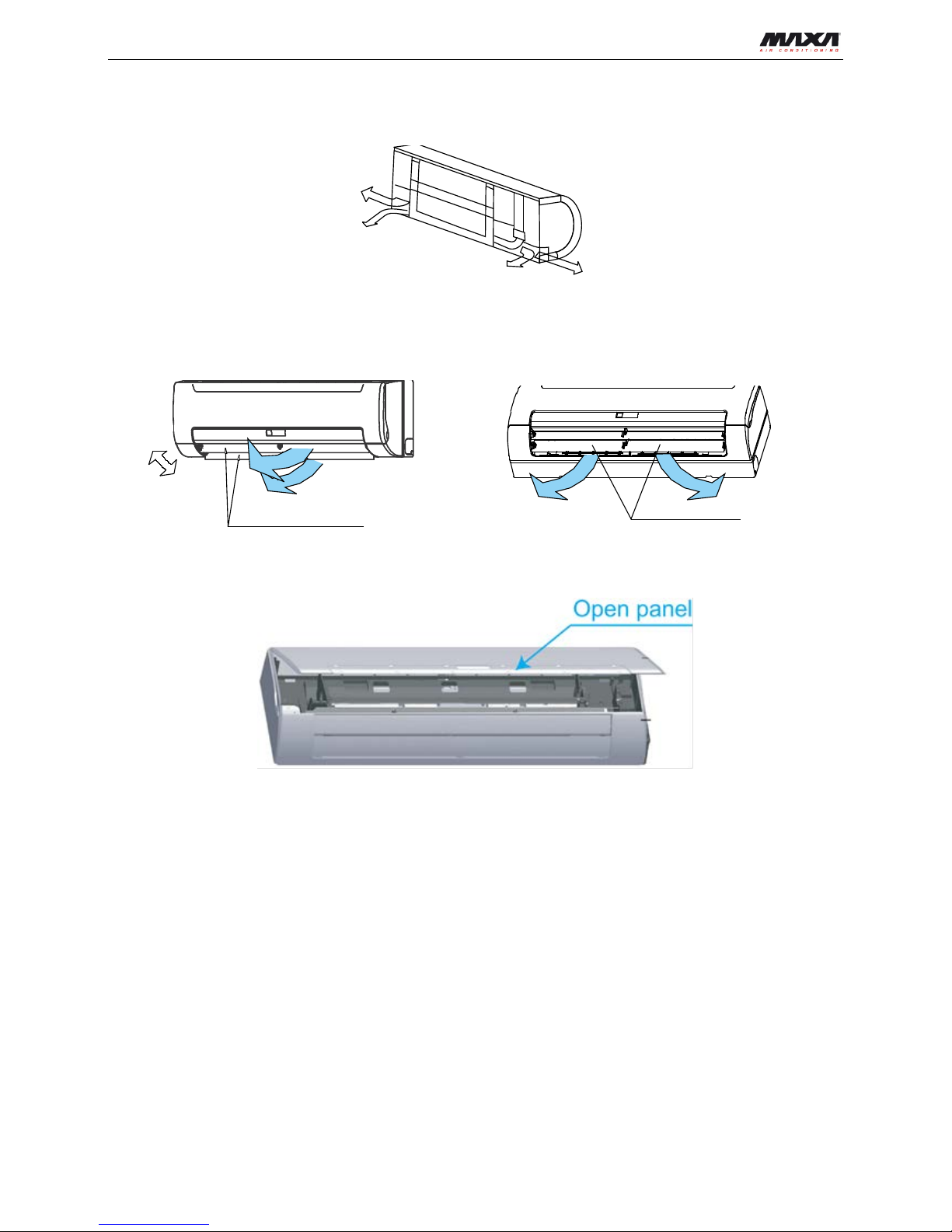
Put the claw at the back of the indoor unit on the hook of the installation board, move the Indoor Unit
from side to side to see that it is secur ely hooked.
Piping can easily lift the indoor unit by the cushioning material between the i ndoor unit an d the wall. Get
Right piping
Left piping
Right back piping
Left back piping
.
.
.
.
.
.
.
.
.
.
.
.
.
.
.
.
.
.
.
.
.
.
.
.
.
.
.
.
.
.
.
.
.
.
.
.
.
.
.
.
.
.
.
.
.
.
.
.
.
.
.
.
.
.
.
.
.
.
.
.
.
.
.
.
.
.
.
.
.
.
.
.
.
.
.
.
.
.
.
.
.
.
.
.
.
.
.
.
.
.
.
.
.
.
.
.
.
.
.
.
.
.
.
.
.
.
.
.
.
.
.
.
.
.
.
.
.
.
.
.
.
.
.
.
.
.
.
.
.
.
.
.
.
.
.
.
.
.
.
.
.
.
.
.
.
.
.
.
.
.
.
.
.
.
.
.
.
.
.
34
Indoor unit outline
Connective pipe
Connective
cable
Drain hose
Connective
pipe
Pipe room
Pond box
Wrapping belt
Indoor unit
.
.
.
.
.
.
.
.
.
.
.
.
.
.
.
.
.
.
.
.
.
.
.
.
.
.
.
.
.
.
.
.
.
.
.
.
.
.
.
.
.
.
.
. .
.

Hydronic Highwall
22 Installation
it out after finish piping.
Push the lower part of the Indoor Unit up to t he wall, and then move the Indoor Unit fro m side to side, up
and down to check if it is hooked securely.
13.5 Water pipe installation
Connection of the water pipe sho uld be done by professiona ls. Double-span should be use d when connecting
pipes of Indoor Unit.
At the first debugging, complet ely expel air from coils via expelling valve.
13.6 Wiring chart
The wiring diagram please refers to chapter 8.
Cautions:
The reserved function is indicat ed in broken line table, users can select it when necessary.
An all-pole disconnection device which has at least 3mm separation distance in all pole and a residual
current device (RCD) with the rating of above 10mA shall be incorporated in the fixed wiring according
to the national rule.
The appliance shall be installe d in a c cor dance with national wiring regulations.
Take out the faceplate, and then dismantle the display cover
Individual connect the power cord and signal line, adjust the dial switch.
hook
Cushioning
material
3-way valve
(4.ports)
discharge
valve
conector
faceplate
display cover plate

Hydronic Highwall
Installation 23
13.6.1 Terminal Board Diagram
Note: The air-conditio ner s can connect with Central Control Monitor (CCM). B efore operation, please wiring
correctly and set system address and network addre s s of indoor units.
Single phase indoor unit
Power supply 220-240V/1 ph/50Hz
Circuit breaker/fuse (A) 15/15
Indoor unit power wiring
Below 20m Twisted pairwire 2.5 mm
2
Below 50m Twisted pairwire 6 mm2
Ground wiring (mm2) 2.5
Please adopt the shielded t w ist ed-pair wire, and connect the shielded layer to E
The reserved wire control function is indicated in broken line table, users can purchase the wire controller
when necessary.
13.6.2 Network address setting
the wire holder of power
cord(three-position)
the wire holder of signal line
(five-position)
display cover plate
dial switch
INDOOR UNIT POWER
220-240V
~
50Hz
XT1
Y/G
DER
KCALB
L N
DER
KCALB
DER
KCALB
ETIHW
KCALB
EULB
1 2
X Y
E
DER
TO Timer
To Central Control Monitor
(CCM)COMM. BUS
XT3
DER
WIRE CONTROLLER
To wire controller
DISPLAY BOARD

Hydronic Highwall
24 Installation
Every air-conditioner in network has only one net work address to distinguish each other. Ad dress code of airconditioner in LAN is set by code switch on Network Inter fac e M odule (NIM), and the set range is 0-63.
Functions of anti-cold wind and anti-hot wind
13.7 Troubleshooting
ON
1
2
ON
1
2
ON
1
2
ON
1
2
SW1
ENC2
~
~
~
~
Toggle switch set
Network address
code
00~15
16~31
32~47
48-63
0
1
2
3
4
5
6
7
8
9
A
B
C
D
E
F
0
1
2
3
4
5
6
7
8
9
A
B
C
D
E
F
0
1
2
3
4
5
6
7
8
9
A
B
C
D
E
F
0
1
2
3
4
5
6
7
8
9
A
B
C
D
E
F
0
1
2
3
4
5
6
7
8
9
A
B
C
D
E
F
0
1
2
3
4
5
6
7
8
9
A
B
C
D
E
F
0
1
2
3
4
5
6
7
8
9
A
B
C
D
E
F
0
1
2
3
4
5
6
7
8
9
A
B
C
D
E
F
ON
1
2
ON
1
2
ON
1
2
ON
1
2
SW2
Toggle switch set
Function selection
Anti-cold wind OFF,
Anti-hot wind OFF
Anti-cold wind OFF,
Anti-hot wind ON
Anti-cold wind ON,
Anti-hot wind OFF
Anti-cold wind ON,
Anti-hot wind ON

Hydronic Highwall
Installation 25
Malfunction code Malfunction
EE
Water-level alarm malfunction
E2
T2 evaporator sensor malfunction
E3
T1 evaporator sensor malfunction
OK
OK
EE: Water-level alarm malfunction
Exist
OK
Water-level switch connecting
wire between switch and main
board gets loose
Reconnect and ensure
that the connection is
reliable.
There is something wrong
with the water-level sw itch
Exist
Replace switch
Chip fault, or chip foot sheds off, or chip is
inverted (correct mode is s emicircular bent
alignment)
Error
Reinstall chip, or install other chip
with same model on the faulty unit,
to check whether there is
something wrong with chip.
Mainboard error:
For example, getting wet
Replace mainboard
OK

Hydronic Highwall
26 Installation
OK
OK
E2: T2 evaporator sensor malfunction
Exist
OK
T2 Connecting wire between s ensor
and mainboard gets loose
Reconnect and ensure that the
connection is reliable.
Temperature sensor is short-
circuited or punctured
Exist
Replace sensor
Chip fault, or chip foot sheds off, or chip is
inverted (correct mode is semicircular bent
alignment)
Error
Reinstall chip, or insta ll other chip w ith same
model on the faulty unit, to check whether
there is something wrong with chip.
Mainboard error:
For example, getting wet
Replace mainboard
OK
OK
OK
E3: T1 evaporator sensor malfunction
Exist
OK
T1 Connecting wire between sensor
and mainboard gets loose
Reconnect and ensure that the
connection is reliable.
Temperature sensor is short-
circuited or punctured
Exist
Replace sensor
Chip fault, or chip foot sheds off, or chip is
inverted (correct mod e is semi circular bent
alignment)
Error
Reinstall chip, or install other chip
with same model on the faulty unit,
to check whether there is
something wrong with chip.
Mainboard error:
For example, getting wet
Replace mainboard
OK

Hydronic Highwall
Installation 27
13.7.1 Troubles and causes of air conditioner
If one of the following malfunctio ns occur, stop operation, shut off the power, and contact with your dealer.
The operation lamp is flashin g r api dly (twice every second)
This lamp is still flashing rapidly after turn off the pow er and t ur n on again.
Remote controller receives malfunction or the button does not work well.
A safet y device such as a fuse, a breaker frequently actuates.
Water leaks from indoor unit.
Other malfunctions.
Solution
Clean the heat exchanger.
Clean the air filter.
Eliminate all dirties and make air
smooth.
Close doors and windows.
Make curtains in order to shelter from
sunshine.
Reduce heat source.
AC cooling capacity reduces (normal).
Sympt
oms Causes
Unit does not start
Air flowing normally but
completely can't cooling
Low cooling effect
Low heating effect
Power failure.
Power switch is off.
Fuse of power switch may have burned.
Batteries of remote controller exhausted
or other problem of controller.
Temperature is not set correctly.
Indoor unit heat exchanger is dirty.
The air filter is dirty.
Inlet of indoor units is blocked.
Doors and windows are open
Sunlight directly shine.
Too much heat resource.
Outdoor temp. is too high.
Wait for the comeback of power.
Switch on the power.
Replace the fuse.
Replace the batteries or check the
controller.
Set the temperature properly.
Use heating device.
Close doors and windows.
Outdoor temperature is lower than 7 C .
Doors and windows not completely
closed.

Hydronic Highwall
28 Installation
13.7.2 Troubles and causes of remote controller
Before asking for serving or r epairing, check the following poi nt s .
Symptoms
Causes
The fan speed can not be
changed.
Check whether the MODE
indicated on the display is
"AUTO"
When the automatic mode is
selected, the air conditioner will
automatically change the fan
speed.
The remote controller signal is
not transmitted even when
the ON/OFF button is pushed.
Check whether the batteries
in the remote controller are
exhausted.
The power supply is off.
No receiving tone sounds
from the indoor unit even
when the ON/OFF button is
pressed.
Check whether the signal
transmitter of the remote
controller is properly directed
to the infrared signal receiver
of the indoor unit when the
ON/OFF button is pressed.
Directly transmit the signal transmitter of
the remote controller to the
infrared signal receiver of the
indoor unit, and then repeatly
push the ON/OFF button twice.
The indication on the display
disappears after a lapse of
time.
Check whether the timer
operation has come to an
end when the TIMER OFF
is indicated on the display.
The air conditioner operation will
stop up to the set time
The TIMER ON indicator
goes off after a lapse of
certain time.
Check whether the timer
operation is started when
the TIMER ON is indicated
on the display.
Up to the set time, the
air conditioner will automatically
start and the appropriate
indicator will go off.
The TEMP. indicator does
not come on.
Check whether the MODE
indicated on the display is
FAN ONLY
The temperature cannot be set during
FAN mode.
Solution
Protection against hot wind in
cooling mode.
Reduce the temperature of inlet in
cooling mode rise the temperature of
inlet in heating mode.
Protection against cold wind in
heating mode.

Hydronic Highwall
Controller 29
14. Controller
14.1 Standard Controller : Remote Controller R51/E
14.1.1 Specifications
Model R51/E
Rated Voltage 3.0V
Lowest Voltage of CPU Emitting Signal 2.0V
Reaching Distance 8m (when using 3.0 voltage, it can get 11m)
Environment Temperature Range -5℃~60℃
14.1.2 Performance Features
1. Operating Mode: COOL、HEAT、DRY、FAN and AUTO.
2. Timer Setting Function i n 24 hour s.
3. Indoor Temperature Se t t ing Ra nge : 17℃~30℃.
4. LCD display for all functions.
5. Compatible with the former R11.
14.1.3 Function Buttons Introduction
1. TEMP DOWN Button: Push the TEMP DOWN button to decrease t he indoor temperature sett ing or t o
adjust the timer in a counter-clockwise direction.
2. MODLE SELECT Button: Each time you push the button, a mode is selected in a sequ ence that goes
from AUTO, COOL, DRY, HE A T and FAN as the following figure indicates:
3. SWING Button: Push this switch button to change the louver angle.

Hydronic Highwall
30 Controller
4. RESET Button: When the RESET button is pushed, all of the current settings are cancelled a nd t he
control will return to the initial settings.
5. ECONOMIC RUNNING Button: Push this button to go into the Energy-Saving operation mode.
6. LOCK Button: Push this button to lock in all the current settings. To release settings, push aga in.
7. CANCEL Button: Push this button to cancel the TIMER settings.
8. TIMER Button: This but t on is used to preset the time ON (st ar t to operate) and the time OFF (turn off
the operation)
9. ON/OFF Button: Push this but t on t o s t ar t t he unit operation. Push the button again to stop the unit
operation.
10. FAN SPEED Button: This button is used for setting fan speed in the sequence that goes fr om AUTO,
LOW, MED to HIGH, and then bac k to Auto.
11. TEMP UP Button: Push this button to increase the indoor temperature setting or t o adjust t he t imer in a
counter-clockwise direction.
12. VENT Button: Pus h this button to set the ventilating mode. The ventilating m ode w ill operate in the
following sequence:
14.1.4 Indicators Introduction
1. TRANSMISSION Indicator: This indicator lights when remote controller transmits signals to indoor unit.
2. MODE Display: Shows the current operation mode - AUTO, COOL, DRY or HE AT. HE AT on ly av ailab le
for heat pump model.
3. HEAT PUMP ONLY- LOCK display is displayed by pushing the LOCK button. Push the LOCK button
again to clear display.
4. TIMER Display: This display area shows the settings of TIMER. That is, if only the starting time of
operation is set, it will display the TI M ER ON. If only the turning off time of operation is set, it will display
the TIMER OFF. If both operation s are set , it will sho w TIMER ON OFF which indicates y ou hav e chosen
to set both the starting time and o ff ti me.
5. FAN Display: When the FAN button is pushed, this signal ind icat or lights.
6. Digital Display Area: This area will show the temperat ure, and if in the TIME R mode, it will show the ON
and OFF settings of the TIM ER.
NOTE: All items are shown in the Fig for the purpose of clear presentation, But during the actual operation
only the relative functional item s ar e shown on the display panel.
14.1.5 Operational Guidelines
14.1.5.1 Operating the Remote Controller
Display Panel
AUTO
COOL
DRY
HEAT
1 6
2
3 4
5
FAN
HIGH
MED
LOW

Hydronic Highwall
Controller 31
Install / Replace Batteries: The Remote Controller uses t w o alkaline dry batteries(R03/Ir03X2).
1. To install batteries, slide back the cover of the battery compartment and install the batteries according to
the directions (+and -) shown on the Remote Controller.
2. To replace the old batteries , use t he same method as mentioned above.
Note :
1. When replacing batteries, do not use old batteries or a different type battery. This may cause the remote
controller to malfunction.
2. If you do not use the remote controller for several weeks remove the batteries. Otherwise battery leakage
may damage the remote controller.
3. The average battery life under normal use is about 6 months.
4. Replace the batteries when ther e is no answering beep from the indoor unit or if the Tran smission Indicator
light fails to appear.
14.1.5.2 Automatic Operation
When the Air Conditioner is ready for use, switch on the power and the OPERATION indicator lamp on the
display panel of the indoor unit st ar ts flashing.
1. Use the MODE select button t o select AUTO.
2. Push the TEMP button to set the desired room temperature. The most comfortable temperature settings
are between 21℃ to 28℃.
3. Push the ON/OFF button to start the air conditioner. The OPERATION lamp on the display panel of the
indoor unit lights. The operating mode of AUTO FAN SPEED is automatically set and there are no
indicators shown on the display panel of the remote controller.
4. Push the ON/OFF butto n again to stop the unit.
Note :
1. In the AUTO mode, the air conditioner can logically choose the mode of COOL, FAN, HEAT and DRY by
sensing the difference between the actual ambient room temperature and the set temperature on the
remote controller..
2. If the AUTO mode is not comfortable for you , the desired mode can be selected manually.
14.1.5.3 COOL, HEAT, and FAN ONLY Operation
1. If the AUTO mode is not comfortable, you may manually override the settings by using COOL, DRY,
HEAT(HEAT PUMP units only), or FAN ONLY modes.
2. Push the TEMP button to set the desired room temperature. When in COOLING mode, the most
comfortable settings are 21℃ or above. When in HEATING mode, t he most c omfortabl e settings are 2 8℃
or below.
3. Push the FAN SPEED to select t he FA N mode of AUTO, HIGH, MED or LOW.
4. Push the ON/OFF butt on. The operation lamp l ights and the air conditio ner st arts to run according to your
settings.
5. Push the ON/OFF butto n again to stop.
Note :
The FAN ONLY mode cannot be used to control the temperature. While in this mode, only steps 1、3 and 4
may be performed.
14.1.5.4 Dry Operation
1. Push the MODE button t o select DRY.
2. Push the TEMP button to set the desired temperature from 21℃ to 28℃.
3. Push the ON/OFF butt on. The operat ion la mp l ight s and the air conditioner star ts to run in th e D RY mode.
4. Push the ON/OFF button again to stop the unit.
Note :
Due to the difference of the set temperat ure of the unit and the act ual indoor temperature, t he Air Conditioner

Hydronic Highwall
32 Controller
when in DRY mode will automatically operate many ti mes w ithout running the COOL and F AN mo de.
14.1.5.5 Time Operation
PUSH TIMER button to set the on and off times of the unit.
1. To set the STARTING time.
1.1 Please push the CANCEL butt on to cancel any former settings.
1.2 Push the TIMER button. The remote controller will show the TIMER and the signal "h" is shown on the
display panel. The control is now r eady to reset the TIMER ON to st ar t the operation.
1.3 Push the TEMP button ( or ) to set desired unit START time .
1.4 After setting the TIMER there will be a one-half second delay before the remote controller transmits the
signal to the Air Conditioner. Then, after approximately another 2 seconds, the set temperature will reappear on the digital display.
2. To set the STOPPING time.
2.1 Please press the CANCEL but t on to cancel any former settings.
2.2 Push the TIMER button and the remote controller will show the last set time for the START operation
and the signal "h" will be shown on the display panel. You are now ready to re-adjust the TIMER OFF to
stop the operation.
2.3 Push the TEMP button to cancel the TIMER ON setting. The d igital area will show "00".
2.4 Push the TIMER button and the remot e controller will show the last set time for t he STOP operation and
the signal "h" will be shown on the display panel. You are now ready to reset the time of the STOP
operation.
2.5 Push the TEMP button ( or ) to set the time you want to stop the operation.
2.6 After setting the TIMER there will be a one-half second delay before the remote controller transmits the
signals to the Air Conditioner. Then after approximately another 2 seconds, the set temperature will reappear on the digital display.
3. Set the STARTING & STOPPING time
3.1 Please press the CANCEL but t on to cancel any former settings.
3.2 Push the TIMER button and the remote controller will show the last setting time for START operation
and the signal "h" will be shown on the display panel. You are now ready to readjust the TIMER ON to
start the operation.
3.3 Push the TEMP button ( or ) to set the time you want to start the operati on.
3.4 Push the TIMER button and the remot e controller will show the last set tim e for STOP operation and the
signal "h" will be shown on the display panel. Y ou are now ready to reset the time of the STOP oper ation.
3.5 Push the TEMP button ( or ) to set the time you want to stop the operation.
3.6 After setting the TIMER there will be a one-half second delay before the remote controller transmits the
signal to the Air Conditioner. Then, after approximately another 2 seconds ,the set temperature will reappear on the digital display.
Note :
1. Please reset the TIMER aft er cancelling the former time set tings.
2. The setting time is relative time. That is the time set is based on t he delay of the current time.
14.2 Optional Controller

Hydronic Highwall
Controller 33
14.2.1 Central Controller: WGC3

Hydronic Highwall
34 Controller

Hydronic Highwall
Controller 35
Liquid crystal matrix display description:
1. The liquid crystal matrix is composed of 4*64 grids, and each grid is co m posed of two blocks of
different sizes (as shown in t he above figure).
2. The matrix includes horizontal coordinates 00-15 on the upper side and vertical coordinat es 00+ , 16+,
32+ and 48+ on the left
Side, which indicate the addr ess of the indoor unit. The sum of the horizontal coordinate and t he
vertical coordinate of the grid is the address of the grid. Each grid cor r esponds to an indoor unit of this
address.
3. One grid is composed of two blocks of different sizes. The status
Indication table is as follow s:
Status
Object
Constantly on Slow blink
Fast blink
Big black block In-service Selected
Out of service
Small black block Power on
Fault of indoor unit Power off
LCD display description
1. Description of the standby page
1) The LCD displays the standby page, 60 air con ditioners are in service, of which 28 are powered on
and 32 off.
2) In the matrix, the big dots of (00, 16+) and (15,32+) are luminous, and the small dot s ar e not luminous.
It indicates the 32 air conditioner s with the addresses from 16 to 47 are powered off.
3) In the matrix, the big and small dots of (09, 48+) and (12, 48+) are not lumino us. I t indicates the four air
conditioners with the addr esses from 57 to 60 are outside the net w ork.
4) All other big and small dots in the matrix are luminous. It indicates all other a ir conditioners are in the
network and powered on.
5) The address of the air conditioner is sum of the coordinates. For example, t he addr ess of (09, 48+) is
09+48=57.
6) The centralized controller keypad is loc ked, and the centralized contro ll er communicates with the
computer normally.

Hydronic Highwall
36 Controller
Query page description
1) The LCD displays the query page, and the air co nditioner with the address o f 08 is being queried.
Mode of the air conditioner with the address 01 is: Cooling, str ong air, swing on, indoor tem per at ur e
22°C, set temperature 20°C, c ooling mode “lock”.
2) In the matrix, only the big and small black dots at ( 00, 00+) and (01, 00+) are lumin ous. I t indicates the
in-service and power-on status of the air conditioner s w it h t he addr esses of 00 and 01.
3) The centralized controller communicates with the computer nor ma lly .
Setting page description
1) The LCD displays the setting page, and qu er ie s the air conditioner with the ad dres s of 08. The mode of
the air conditioner with the addr ess 08 is: Cooling, strong air, swi ng on, i ndoor temperature 28°C, set
temperature 22°C, cooling .
2) In the matrix, only the big black dots from (08, 00+ ) to (16, 00+) are luminous. It indicates the air
conditioners with the addr esses from 08 to 16 are in service.
3) The centralized controller communic at es with the computer normally.
Fault page display descript ion
1) Query the air conditioner with the address o f 08 in the query page. The air conditi oner with the address
of 08 is faulty, and the fault code is 08. T he big black dot below (08, 0+) blin ks.
2) In the matrix, only the big and small black dots from (00, 00+) to (16, 15+) illu m inate. It indicates the in-
service status of the air condit i oners with the addresses o f 00 an d 01.
3) The centralized controller communic at es with the computer normally.


I dati riportati nella presente documentazione sono solamente
indicativi. Il costruttore si riserva la facoltà di apportare in qualsiasi
momento tutte le modifiche ritenute necessarie.
The data indicated in this manual are purely indicative. The
manufacturer reserves the right to modify the data whenever it is
considered necessary.
Via S. G. LAvoratore 24 (Loc. La Macia)
37040 Arcole
Verona - Italy
Tel. +39 - 045.76.36.585
Fax +39 - 045.76.36.551
www.maxa.it
e-mail: info@advantixspa.it
A I R C O N D I T I O N I N G
 Loading...