

Page 1
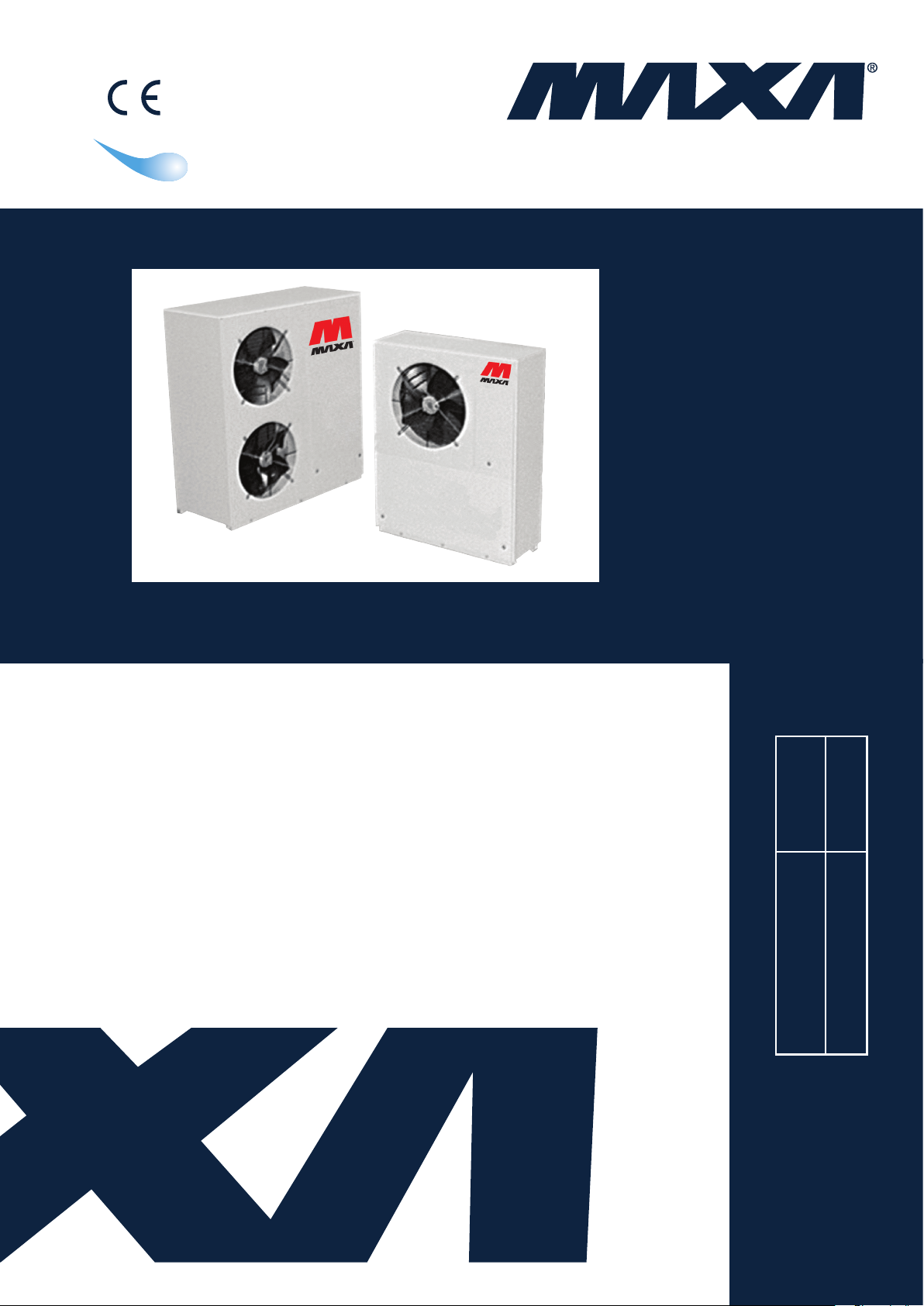
A I R C O N D I T I O N I N G
MANUALE TECNICO
R22
R407c
R410a
TECHNICAL MANUAL
MANUEL TECHNIQUE
TECHNISCHES HANDBUCH
REFRIGERATORI D’ACQUA E
POMPE DI CALORE ARIA/ACQUA
CON VENTILATORI ASSIALI,
COMPRESSORI ROTATIVI/SCROLL
E GRUPPO DI POMPAGGIO DA 4
kW A 20 KW
AIRCOOLED LIQUID
CHILLERS AND HEAT
PUMPS WITH AXIAL FANS,
ROTARY/SCROLL COMPRESSORS
AND PUMP SECTION
FROM 4 kW TO 20 kW
FLÜSSIGKEITSKÜHLER UND WÄRMEPUMPE LUFTGEKÜHLT,
MIT AXIALLÜFTERN, UMLAUFENDER/SCROLL VERDICHTERN UND
PUMPEN SEKTION
VON 4 kW BIS 20 kW
GROUPES DE PRODUCTION D’EAU
GLACÉE ET POMPES À CHALEUR À
CONDENSATION À AIR AVEC
VENTILATEURS AXIAUX,
COMPRESSEURS ROTATIF/SCROLL
ET GROUPE POMPAGE
DE 4 kW À 20 kW
06-09
09-07
Emissione/Edition/Au-
sgabeIssue
Sostituisce/Superseedes
Ersetzt/Remplace
HWAL-A 15÷81
MTE0111072004-01
Serie/Series/Serie/Série
Catalogo/Catalogue/Katalog/Brochure
A26
Page 2

HWAL-A 15÷81
2
Page 3

HWAL-A 15÷81
INDICE
Descrizione generale
•
• Versioni
• Caratteristiche costruttive
• Accessori forniti separatamente
•
Dati tecnici generali
• Dati elettrici
Rese in raffreddamento
•
• Rese in riscaldamento
•
Prevalenza utile pompa di circolazione
•
Coefcienti correttivi per fattori di
sporcamento
• Limiti di funzionamento
• Schema circuito frigorifero e idraulico
unità per solo raffreddamento
unità a pompa di calore
•
Utilizzo di miscele acqua/glicole etilenico
• Livelli di pressione sonora
•
Dimensioni di ingombro, pesi, spazi di
rispetto e collegamenti idraulici
• Schemi elettrici
•
Legenda schemi elettrici
• Consigli pratici per l’installazione
Pag.
10
11
11
12
13
14
16
18-19
20-21
22
23
INDEX
4
4
4
4
6
6
8
9
General description
•
Versions
•
Technical features
•
•
Separately supplied accessories
Technical data
•
Electrical data
•
Cooling capacity
•
Heating capacity
•
•
Circulation pump available static pressure
• Fouling factor corrections
Operating range
•
•
Refrigerant / hydraulic chiller circuit diagram
Pag.
4
4
4
4
6
6
8
9
10
11
11
circuit diagram
only cooling units
heat pump units
Operation with ethylene glycol mixtures
•
Sound pressure level
•
Dimensions, weights, clerances and
•
hydraulic connections
Electrical diagrams
•
Explanation of electrical diagrams
•
Installation recommendations
•
12
13
14
16
18-19
20-21
22
23
INDEX
•
Allgemeine Eingeschaften
•
Bauvarianten
• Konstruktionsmerkmale
• Lose mitgelieferten Zubehöre
•
Allgemeine technische Daten
• Elektrische Daten
• Kälteleistungen
• Heizleistungen
•
Externe statische Pressung der Umlaufpumpe
•
Korrekturkoefzienten für
Verschmutzungsfaktoren
• Einsatzbereich
• Wasser und Kältekreislaufschema
nur zu Kühlung Einheiten
Wärmepumpe Einheiten
•
Verwendung von
Wasser/Ethylenglikol-Mischungen
• Schalldruckpegel
•
Außenmaße, Gewichte, Raumbedarf
und hydraulische Anschlüsse
•
Schaltpläne
•
Schaltpläne Erklärung
• Hinweise zur Installation
Seite
10
11
11
12
13
15
17
18-19
20-21
22
23
INDEX
5
5
5
5
7
7
8
9
•
Description générale
Différentes versions
•
•
Caractéristiques
Accessoires fournis separement
•
•
Caractéristiques techniques générales
Caractéristiques électriques
•
Puissance frigorique
•
Puissance calorique
•
•
Pression utile de la pompe de circulation
•
Coefcients correcteurs pour
facteurs d’encrassements
• Limites de fonctionnement
Schemat du circuit hydraulique et frigorique
•
groupe de production d’eau glacée
unité à pompe à chaleur
Utilisation de la solution eau/glycol ethylenique
•
Niveaux de pression sonore
•
Encombrements, poids, espaces pour
•
entretien et raccordements hydrauliques
Diagrammes électriques
•
Explication de le diagrammes électriques
•
Conseils pratiques pour l’installation
•
Pag.
5
5
5
5
7
7
8
9
10
11
11
12
13
15
17
18-19
20-21
22
23
3
Page 4

HWAL-A 15÷81
DESCRIZIONE GENERALE
Refrigeratori d’acqua condensati ad aria con ventilatori assiali per
installazione esterna. La gamma comprende 10 modelli che coprono potenzialità frigorifere da 4 a 20 kW.
VERSIONI:
HWAL-A - solo raffreddamento con serbatoio e pompa
HWAL-A/WP - pompa di calore reversibile con serbatoio e
pompa
CARATTERISTICHE COSTRUTTIVE:
Struttura. A telaio portante, è realizzata in peraluman e lamiera zin-
cata ed è dotata, alla base, di supporti antivibranti in gomma. Viteria
in acciaio inox.
Compressori. Rotativo ermetico monofase (15÷25), Scroll ermetico monofase (31-41) e Scroll ermetico trifase (51÷81) completi di
protezione interna (klixon) e resistenza carter, ove il costruttore lo
preveda, montati su supporti antivibranti in gomma.
Ventilatori. Di tipo assiale a basso numero di giri e profilo alare
speciale, sono direttamente accoppiati a motori a rotore esterno con
grado di protezione IP44. Una rete antinfortunistica è posta sull’uscita dell’aria.
Condensatore. Costituito da una batteria alettata con tubi di rame
ed alette in alluminio, completo di vaschetta raccogli condensa per
la versione a pompa di calore.
Evaporatore. Del tipo a piastre saldobrasate in acciaio inox AISI
316, inserito all’interno del serbatoio.
Quadro elettrico. Include: sezionatore generale con dispositivo
bloccoporta, fusibili, filtro antidisturbo, teleruttore compressore e
teleruttore pompa (51÷81).
Microprocessore per la gestione automatica delle seguenti funzioni:
regolazione della temperatura dell’acqua, protezione antigelo, temporizzazione del compressore, reset allarmi, contatto cumulativo d’allarme per segnalazione remota, commutazione locale o remota del ciclo
raffreddamento/riscaldamento nelle pompe di calore, visualizzazione
su display per: ciclo di funzionamento (raffreddamento o riscaldamento), compressore richiesto/attivato, temperatura dell’acqua di ritorno
dell’impianto, set temperatura e differenziali impostati, codice allarmi.
Dispositivo elettronico proporzionale per l’attenuazione del livello
sonoro, ottenuta mediante regolazione in continuo della velocità di
rotazione dei ventilatori; tale dispositivo permette anche il funzionamento dell’unità in raffreddamento fino a temperature dell’aria
esterna di -20 °C.
GENERAL DESCRIPTION
Air cooled water chiller units, with axial fans for outdoor installation.
The range consists of 10 models covering a cooling capacity from 4
to 20 kW.
VERSIONS:
HWAL-A - cooling only with storage tank and pump
HWAL-A/WP - reversible heat pump with storage tank and
pump
TECHNICAL FEATURES:
Structure. With supporting frame, in peraluman, galvanized sheet and
with rubber shock absorbers on the frame. Stainless-steel screws.
Compressor. Rotary 1-phase (15÷25), 1-phase Scroll ermetic compressor (31-41) and 3-phase Scroll ermetic compressor (51÷81),
complete with overload protection (klixon) embedded in the motor
and crankcase, if needed, installed on rubber vibrations absorbing.
Fans. Axial fan type low ventilation and special wing profile, they are
directly coupled to external rotor motors with protection grade IP44,
and a safety fan guard fitted on discharge air flow.
Condenser. Copper tubes and aluminium finned coil, complete with
moisture drain pan in the heat pump version.
Evaporator. In AISI 316 stainless steel brazewelded plates type,
built-in the storage tank.
Electrical panel. Includes: main switch with door lock device, fuses,
lter for harmonic current, compressor contact and pump contact
(51÷81).
Microprocessor to control following functions: regulation of the
water temperature, antifreeze protection, compressor timing, alarm
reset, potential free contact for remote general alarm, local or
remote cooling / heating changeover (operating in heat pump),
visual system with digital display: running cycle (cooling or heating),
compressor delay relay/on, inlet water temperature, set point and
differential setting, alarm decodification.
Electronic proportional device to decrease the sound level, with a
continuous regulation of the fan speed. This device allows also the
cooling functioning of the unit by external temperature till -20°C.
Versione HWAL-A
Circuito frigorifero. Il circuito, realizzato in tubo di rame, include:
filtro disidratatore, valvola d’espansione e pressostato di alta a
riarmo manuale.
Circuito idraulico. Il circuito, realizzato in tubo di rame, include:
pressostato differenziale acqua, valvola di sfiato aria manuale,
serbatoio coibentato, circolatore (15÷41) o pompa (51÷81), valvola di sicurezza (3 bar), manometro, rubinetto di carico e scarico
impianto e vaso di espansione inserito all’interno del serbatoio.
Versione HWAL-A/WP
Circuito frigorifero. Il circuito, realizzato in tubo di rame, include:
filtro disidratatore bidirezionale, valvole d’espansione, valvole di
ritegno, valvola di inversione a quattro vie e pressostato di alta a
riarmo manuale.
Circuito idraulico. Il circuito, realizzato in tubo di rame, include:
pressostato differenziale acqua, valvola di sfiato aria manuale,
serbatoio coibentato, circolatore (15÷41) o pompa (51÷81), valvola di sicurezza (3 bar), manometro, rubinetto di carico e scarico
impianto e vaso di espansione inserito all’interno del serbatoio.
ACCESSORI FORNITI SEPARATAMENTE:
PB - Pressostato bassa pressione a riarmo manuale.
CR - Pannello comandi remoto da inserire in ambiente per il co-
mando a distanza dell’unità, con funzioni identiche a quello inserito
in macchina.
IS - Interfaccia seriale RS 485 per collegamento a sistemi di
controllo e di supervisione centralizzati.
RP - Reti protezione batteria in acciaio con trattamento di cataforesi e verniciatura.
HWAL-A Version
Refrigerant circuit. The circuit, in copper tubing, includes: dryer lter,
expansion valves and manual reset high pressure switch.
Water circuit. The circuit, in copper tubing, includes: water differential
pressure switch, manual air release valve, insulated tank, circulator
(15÷41) or pump (51÷81), safety valve (3 bar), gauge, plant charge
and discharge shut off valve and expansion vessel inserted in the
storage tank.
HWAL-A/WP Version
Refrigerant circuit. The circuit, in copper tubing, includes: bi-direc-
tional dryer lter, expansion valves, check valves, 4-ways reverse
valve, manual reset high pressure switch.
Water circuit. The circuit, in copper tubing, includes: water differential
pressure switch, manual air release valve, insulated tank, circulator
(15÷41) or pump (51÷81), safety valve (3 bar), gauge, plant charge
and discharge shut off valve and expansion vessel inserted in the
storage tank.
SEPARATELY SUPPLIED ACCESSORIES:
PB - Manual reset low pressure switch.
CR - Remote control panel to be inserted in the room for remote
control of the unit, with the same functions as that inserted in the
machine.
IS - RS 485 serial interface for connection to controls and centralized supervision systems.
RP - Coil protection guards in steel with cataphoresis treatment
and painting.
4
Page 5

HWAL-A 15÷81
ALLGEMEINE EIGENSCHAFTEN
Luftgekühl t e Fl ü s s i k eitskühler mit Axia l v e n t ilatoren für
Aussenaufstellung. Die Produktpalette besteht aus 10 Modellen, die
Kälteleistungsbereich von 4 bis 20 kW abdecken.
BAUVARIANTEN:
HWAL-A - nur zur Kühlung mit Speicher und Pumpe
HWAL-A/WP - reversibler Wärmepumpe mit Speicher und
Pumpe
KONSTRUKTIONSMERKMALE:
Struktur. Mit tragendem rahmen aus Peraluman, verzinktem Blech und
mit Gummi Schwingungsdämpfer auf dem Grundrahmen. Schrauben
aus Edelstahl.
Verdichter. Einphasischer Umlaufender (15÷25), 1-phasisch Scroll
hermetischer (31-41) und 3-phasisch Scroll hermetischer (51÷81),
komplett mit innerem Thermoschutzschalter (klixon) und Ölwannenheizung, wenn nötig; auf Dampfungshalterungen aus Gummi.
Ge b l ä s e . D ie Ax ia l g e b lä s e s in d di re k t mit e in em
Ei n ph as e ne le k tr om o to r g e k op pe l t u nd m i t in te rn e m
Thermoschutzschalter ausgestattet. Der Motor ist nach Schutzart
IP44 hergestellt, und die Gebläse sind zwecks Unfallverhütung mit
einem Schutzgitter auf der Luftausblasseite ausgestattet.
Kondensator. Gerippter Verflüssigerregister mit Aluminium
Lamellen und Kupferrohren, für die Wärmepumpe Version komplett
mit Kondensatbehälter.
Verdampfer. Plattenverdampfer aus rostfreiem Stahl AISI 316 in
dem Speicher eingebaut.
Schaltschrank. Einschliesslich Hauptschalter mit Türverriegelung,
sicherungen, Filter für harmonische Ströme, Verdichter Kontakt und
Pumpe Kontakt (51÷81).
Mikroprozessor für die Steuerung der folgenden Funktionen:
Wa ssert empera turre gelung , F rostschutz, Takt steuer ungen
der Kompresso ren, Alarm-Reset, Alar msammelko ntakt f ür
Fernmeldung und Umschalter Lokal oder Fernsteuerung vom
Kühl- oder Heizzyklus der Wärmepumpen. Displayanzeige für:
Betriebszyklus (Kühlen oder Heizen), Kompressor Stand by/On,
Wassertemperatur am Verdampfereingang, Einstellwert u.Differenz,
Alarmbeschreibung.
Elektronische proportionale Vorrichtung zur Schalldämpfung
mit einer modulanten Lüfter Drehzahlregelung. Diese Vorrichtung
ermöglicht den Kühlbetrieb der Einheit auch bei externer Temperatur
bis -20°C.
DESCRIPTION GÉNÉRALE
Groupe d’eau glacée à condensation à air avec ventilateurs axiaux
pour installation à l’extérieur. La gamme est composée de 10 modèles d’une puissance de 4 iusqu’à 20 kW.
DIFFÉRENTES VERSIONS:
HWAL-A - froid seul avec ballon tampon et pompe
HWAL-A/WP - pompe à chaleur réversible avec ballon tampon
et pompe
CARACTERISTIQUES:
Structure. À cadre portant, est réalisée en peraluman et en tôle
galvanisée et il est doué, à la base, de supports antivibratiles en
caoutchouc. Vis en acier inox.
Compresseur. Du type rotatif hermétique monophase (15÷25),
Scroll monophase (31-41) et Scroll triphase (51÷81) avec protection
thermique interne par klixon, si nécessaire réchauffeur de carter et
montés sur supports antivibrants en caoutchouc.
Ventilateurs. De type axial directement accouplées à un moteur
éléctrique monophase, avec protection thérmique interne par klixon.
La classe de protection du moteur est en IP44, at les ventilateurs
comprennent une grille de protection et de sécurité.
Condenseur. Batterie en tube de cuivre et ailettes d’aluminium,
complète de bac à condensats dans la version pompe à chaleur.
Évaporateur. À plaques soudo-brasées en acier inox AISI 316 inserée à l’interieur de l’unité.
Tableau électrique. Inclus: sectionneur général avec dispositif de blo-
cage de porte, fusibles, ltre pour courants harmoniques, télérupteur
compresseur et télérupteur pompe (51÷81).
Microprocesseur pour le contrôle des fonctions suivantes: régulation
de la température de l’eau, protection antigivre, temporisation des compresseurs, réarmement alarmes, boucles sèches pour signalisation des
alarmes à distance et commutation locale ou à distance du cycle refroidissement/chauffage dans les pompes à chaleur. Visualisation sur
écran pour: cycle de fonctionnement (refroidissement ou chauffage),
compresseur standby/on, température de l’eau d’entrée, consigne température et différentiel prévus, désignation des alarmes.
Dispositif électronique proportionnel pour l’atténuation du niveau
sonore, obtenue au moyen de régulation en continu de la vitesse de
rotation des ventilateurs. Cet dispositif permet aussi le fonctionnement de l’unité en refroidissement jusq’à des températures de l’air
extérieur de -20 °C.
HWAL-A bauvariante
Kältekreislauf. Kreislauf aus Kupferrohren mit Entfeuchtungsfilter, Ex-
pansionsventil und Hochdruckschalter mit manueller Rückstellung.
Wasserkreislauf. Wasserkreislauf aus Kupferrohren mit differentialem Wasserdruckschalter, manuellem Entlüfungsventil, Behälter mit
Isolierung, Umwälzpumpe (15÷41) oder Pumpe (51÷81), Sicherheitsventil (3 bar), Manometer, Anlage Druck und Abfluss mit Absperventile
und Ausdehnungsgefäß in dem Speicher eingebaut.
HWAL-A/WP bauvariante
Kältekreislauf. Kreislauf aus Kupferrohren mit zweiseitig gerichtetem
Entfeuchtungsfilter, Expansionsventil, Rückschlagventilen, 4-WegeUmschaltventil und Hochdruckschalter mit manueller Rückstellung.
Wasserkreislauf. Wasserkreislauf aus Kupferrohren mit differentialem Wasserdruckschalter, manuellem Entlüfungsventil, Behälter mit
Isolierung, Umwälzpumpe (15÷41) oder Pumpe (51÷81), Sicherheitsventil (3 bar), Manometer, Anlage Druck und abfluss mit absperventile
und Ausdehnungsgefäß in dem Speicher eingebaut.
LOSE MITGELIEFERTEN ZUBEHÖRE:
PB - Niedrigdruckschalter mit manuellem Reset.
CR - Fernbedienung, die am Standort installiert wird und von der
aus eine Fernsteuerung der Einheit möglich ist. Mit den gleichen
Funktionen wie das Gerät.
IS - Serielle Schnittstelle RS 485 für den Anschluss an Kontrolllsysteme oder zentrale Supervisor.
RP - Schutzgitter Verüssigerregister aus Stahl mit Kataphoresebehandlung und Lackierung.
Version HWAL-A
Circuit frigorique. Le circuit, réalisé en tuyau de cuivre, inclut: ltre
déshydrateur, soupape d’expansion et pressostat de haute pression
à réarmement manuel.
Circuit hydraulique. Le circuit, réalisé en tuyau de cuivre, inclut:
pressostat différentiel eau, purge d’air manuel, réservoir calorifugé,
circulateur (15÷41) ou pompe (51÷81), soupape de sûreté (3 bar),
manomètre, robinet de charge et décharge installation vase d’expansion inserée à l’interieur de l’unité.
Versions HWAL-A/WP
Circuit frigorique. Le circuit, réalisé en tuyau de cuivre, inclut:
ltre déshydrateur bi-directionnel, soupape d’expansion, soupape de
retenue, soupape d’inversion à quatre voies et pressostat de haute
pression à réarmement manuel.
Circuit hydraulique. Le circuit, réalisé en tuyau de cuivre, inclut:
pressostat différentiel eau, purge d’air manuel, réservoir calorifugé,
circulateur (15÷41) ou pompe (51÷81), soupape de sûreté (3 bar),
manomètre, robinet de charge et décharge installation et vase d’expansion inserée à l’interieur de l’unité.
ACCESSOIRES FOURNIS SEPAREMENT:
PB - Pressostat basse pression à réarmement manuel.
CR - Tableau de commandes à distance à insérer dans un envi-
ronnement pour la commande à distance de l’unité, avec fonctions
identiques à celles insérées dans la machine.
IS - Interface de série RS 485 pour branchement à système de
contrôle et de supervision centralisées.
RP - Réseaux de protection batterie en acier avec traitement
cataphorèse et vernissage.
5
Page 6
R410A
HWAL-A 15÷81
DATI TECNICI GENERALI
TECHNICAL DATA
MODELLO 15 18 21 25 31 41 51 61 71 81 MODELL
Raffreddamento: Cooling:
Resa nominale kW 4,2 5,1 6,4 7,5 8,6 10,4 12,2 15,3 18,6 20,5 Nominal capacity
Riscaldamento: Heating:
Resa nominale kW 5,0 6,0 8,0 8,7 10,3 12,4 14,8 18,8 21,9 24,4 Nominal capacity
Compressori: Compressor:
Numero n° 1 1 1 1 1 1 1 1 1 1 Number
Tipo < - - - - - - Rotary - - - - - - - > < - - - - - - - - - - - - - Scroll - - - - - - - - - - - - - > Type
Potenza ass. in raffreddamento
Potenza ass. in riscaldamento
Ventilatori: Fans:
Portata aria m³/s 0,97 0,97 0,89 0,89 0,82 0,82 1,94 1,78 1,78 1,64 Air ow
N° x Potenza installata n°x kW 1X0,14 1x0,14 1x0,14 1x0,14 1x0,14 1x0,14 2x0,14 2x0,14 2x0,14 2x0,14 N° x nominal input
Carica refrigerante: Refrigerant charge:
Versione solo raffreddamento kg 1,6 1,7 1,9 2,1 2,3 2,4 3,6 4,0 4,4 4,5 Cooling only
Versione a pompa di calore kg 1,8 1,9 2,1 2,3 2,4 2,5 4,1 4,5 4,9 5,0 Heat pump version
Pressione sonora (1) dB(A) 56 56 56 56 58 59 59 59 59 59 Sound pressure (1)
Pressione sonora (2) dB(A) 49 49 49 49 51 52 51 51 51 51 Sound pressure (2)
Carica olio: kg 0,4 0,4 0,6 0,6 0,7 1,0 1,6 1,6 1,6 1,6 Oil charge:
Circuito idraulico:
Portata acqua l/s 0,20 0,24 0,31 0,36 0,41 0,50 0,58 0,73 0,89 0,98 Water ow
Potenza nom. pompa kW 0,20 0,20 0,20 0,20 0,20 0,21 0,30 0,30 0,30 0,30 Pump nominal power
Prevalenza utile kPa 52 48 35 45 41 42 140 123 90 80 Available static pressure
Contenuto d’acqua serbatoio l < - - - - - -- - - - - - - - - 25 - - - - - - - - - - - - > < - - - - - - - - 50 - - - - - - - > Water volume capacity
Vaso d’espansione l 3,4 3,4 3,4 3,4 3,4 3,4 3,4 3,4 3,4 3,4 Expansion vessel
Attacchi idraulici ”G 3/4” 3/4” 3/4” 3/4” 3/4” 3/4” 1” 1” 1” 1” Water connections
kW 1,3 1,6 2,0 2,4 2,8 3,4 3,7 4,7 5,7 6,3 Cooling power input
kW 1,6 1,9 2,5 2,8 3,4 4,1 4,5 5,9 6,8 7,7 Heating power input
Water circuit:
Pesi * :
Peso di trasporto Kg 96 98 106 110 118 120 192 194 196 198 Transport weight
Peso in esercizio Kg 121 123 131 135 143 145 242 244 246 248 Operating weight
DATI ELETTRICI
Weight * :
ELECTRICAL DATA
MODELLI 15 18 21 25 31 41 51 61 71 81 MODELL
Massima potenza assorbita kW 1,9 2,3 2,8 2,9 3,7 4,1 4,8 5,6 6,6 7,3 Maximun absorbed power
Corrente max allo spunto A 39 43 62 62 79 86 58 61 78 106 Maximun starting current
Corrente massima assorbita A 7 9 11 13 15 19 12 13 15 17 Full load current
Pot. nomin. motore ventilatore
Corrente. nomin. motore ventilat.
Pot. nomin. motore pompa kW 0,20 0,20 0,20 0,20 0,20 0,21 0,30 0,30 0,30 0,30
Corrente. nomin. motore pompa
Alimentazione elettrica V/~/Hz <- - - - - - - - - 230/1/50 ±5% - - - - - - - - -> <- - - 400/3+N/50 ±5% - - ->
Alimentazioni ausiliari V/~/Hz <- - - - - - - - - - - - - - - - - - - - 230-24/1/50 ±5% - - - - - - - - - - - - - - - - - - - ->
Raffreddamento: temperatura aria esterna 35°C; temperatura acqua
ingresso/uscita evaporatore 12/7 °C.
Riscaldamento: temperatura aria esterna 7°C b.s., 6°C b.u.;
temp. acqua ingresso/uscita condensatore 40/45 °C.
* Pesi: per le unità a pompa di calore maggiorare il peso del 10%.
(1) Livello di pressione sonora rilevato in campo libero ad 1 m
dall'unità e 1.5 m dal suolo. Secondo la DIN 45635.
(2) Livello medio di pressione sonora in campo libero a 1 m
dall'unità, come definito dalla ISO 3744.
kW <- - - - - - - - - - - 1 x 0,14 - - - - - - - - - - -> <- - - - - - 2 x 0,14 - - - - ->
A <- - - - - - - - - - - 1 x 0,58 - - - - - - - - - - -> <- - - - - - 2 x 0,58 - - - - ->
A 0,84 0,84 0,84 0,84 0,84 0,98 2,5 2,5 2,5 2,5
Cooling: ambient air temperature 35°C;
evaporator water temperature in/out 12/7 °C.
Heating: ambient air temperature 7°C d.b., 6°C b.w.;
condenser water temperature in/out: 40/45°C.
* Weights: for heat pump unit increase the weight 10%.
(1) Sound pressure level measured in free eld condictions at 1 m from
the ground. According to DIN 45635.
(2) Average sound pressure level measured in free eld condictions at
1 m, as dened by ISO 3744.
Fan motor nomin. abs. power
Fan motor nomin. abs. current
Pump motor nomin. abs. power
Pump motor nomin. abs. current
Power supply
Control power supply
6
Page 7

HWAL-A 15÷81
R410A
ALLGEMEINE TECHNISCHE DATEN
CARACTERISTIQUES TECHNIQUES GENERALES
MODELL 15 18 21 25 31 41 51 61 71 81 MODÈLE
Kälteleistung: Refroidissement:
Nennleistung kW 4,2 5,1 6,4 7,5 8,6 10,4 12,2 15,3 18,6 20,5 Puissance nominale
Heizleistung: Chauffage:
Nennleistung kW 5,0 6,0 8,0 8,7 10,3 12,4 14,8 18,8 21,9 24,4 Puissance nominale
Verdichter: Compresseur:
Anzahl n° 1 1 1 1 1 1 1 1 1 1 Nombre
Typ < - - - - - - Rotary - - - - - - - > < - - - - - - - - - - - - - Scroll - - - - - - - - - - - - - > Type
Leist.-Aufn.Kühlb. kW 1,3 1,6 2,0 2,4 2,8 3,4 3,7 4,7 5,7 6,3 Puissance absorbée froid
Leist.-Aufn.Heizb. kW 1,6 1,9 2,5 2,8 3,4 4,1 4,5 5,9 6,8 7,7 Puissance absorbée chaud
Lüftern: Ventilateurs:
Luftmenge m³/s 0,97 0,97 0,89 0,89 0,82 0,82 1,94 1,78 1,78 1,64 Débit d'air
Luftleistung n°x kW 1X0,14 1x0,14 1x0,14 1x0,14 1x0,14 1x0,14 2x0,14 2x0,14 2x0,14 2x0,14 Puissance installée
Kältemittelfüllung: Charge refrigerant
Nur zur Kühlung kg 1,6 1,7 1,9 2,1 2,3 2,4 3,6 4,0 4,4 4,5 Version froid seul
Wärmepumpe-Ausf. kg 1,8 1,9 2,1 2,3 2,4 2,5 4,1 4,5 4,9 5,0 Version pompe à chaleur
Schalldruckpegel (1) dB(A) 56 56 56 56 58 59 59 59 59 59 Pression sonore (1)
Schalldruckpegel (2) dB(A) 49 49 49 49 51 52 51 51 51 51 Pression sonore (2)
Ölfüllung kg 0,4 0,4 0,6 0,6 0,7 1,0 1,6 1,6 1,6 1,6 Charge d'huile
Wasserkreislauf:
Wassermenge l/s 0,20 0,24 0,31 0,36 0,41 0,50 0,58 0,73 0,89 0,98 Débit d’eau
Pumpennleistung kW 0,20 0,20 0,20 0,20 0,20 0,21 0,30 0,30 0,30 0,30 Puissance nom. pompe
Ext. statische Pressung kPa 52 48 35 45 41 42 140 123 90 80 Pression utile
Speicherinhalt l < - - - - - -- - - - - - - - - 25 - - - - - - - - - - - - > < - - - - - - - - 50 - - - - - - - > Volume d’eau
Ausdehnungsgefäß l 3,4 3,4 3,4 3,4 3,4 3,4 3,4 3,4 3,4 3,4 Vase d’expansion
Wasseranschlüsse ”G 3/4” 3/4” 3/4” 3/4” 3/4” 3/4” 1” 1” 1” 1” Raccords hydrauliques
Circuit hydraulique:
Gewicht * :
Transportgewicht Kg 96 98 106 110 118 120 192 194 196 198 Poids d’expédition
Betriebsgewicht Kg 121 123 131 135 143 145 242 244 246 248 Poids en opération
ELEKTRISCHE DATEN
CARACTERISTIQUES ELECTRIQUES
Poids * :
MODELL 15 18 21 25 31 41 51 61 71 81 MODÈLE
Max. Leistungsaufnahme kW 1,9 2,3 2,8 2,9 3,7 4,1 4,8 5,6 6,6 7,3
Max. Anlaufstrom A 39 43 62 62 79 86 58 61 78 106
Max. Stromaufnahme A 7 9 11 13 15 19 12 13 15 17
Ventilatormotor-Nennleistung
Ventilatormotor-Nennstrom A <- - - - - - - - - - - 1 x 0,58 - - - - - - - - - - -> <- - - - - - 2 x 0,58 - - - - ->
Pumpenmotor-Nennleistung kW 0,20 0,20 0,20 0,20 0,20 0,21 0,30 0,30 0,30 0,30
Pumpenmotor-Nennstrom A 0,84 0,84 0,84 0,84 0,84 0,98 2,5 2,5 2,5 2,5
Stromversorgung V/~/Hz <- - - - - - - - - 230/1/50 ±5% - - - - - - - - -> <- - - 400/3+N/50 ±5% - - ->
Stromversorgung der Hilfseinricht
Kälteleistung: Umgebungstemperatur 35°C;
Kaltwasserein / austrittstemperatur am Verdampfer 12/7 °C.
Heizleistung: Umgebungstemperatur 7°C t.k.t., 6°C f.k.t.;
Kühlwasserein / austrittstemperatur am Verflüssiger 40/45 °C.
* Gewichts: für Wärmepumpen modelle erhöht sich das Gewicht um 10%.
(1) Messung in einem Meter Abstand gegenüber der
Verflüssigerseite, in einer Höhe von 1 m. Gebäß DIN 45635
(2) Mittlerer Schalldrunk in 1 m vor der Einheit in freien Feld, wie
von ISO 3744 angegeben.
kW <- - - - - - - - - - - 1 x 0,14 - - - - - - - - - - -> <- - - - - - 2 x 0,14 - - - - ->
V/~/Hz <- - - - - - - - - - - - - - - - - - - - 230-24/1/50 ±5% - - - - - - - - - - - - - - - - - - - ->
Froid : Température air extérieur 35°C;
Température eau entrée / sortie évaporateur 12/7°C.
Chaud: Température air extérieur : 7°C d.s., 6°C b.h.;
Température eau entrée sortie condenseur : 40/45°C.
* Poids: pour les unités en pompe à chaleur majorer le poids de 10%.
(1) Niveau de pression sonore mèsuré en champ libre à 1 m de l'unité.
Selon le normes DIN 45635.
(2) Niveau moyen de pression sonore en champ libre à 1 m de l'unité,
comme déni de ISO 3744.
Puissance absorbée max.
Intensité de démarrage max.
Intensité absorbée max.
Puissance nom.moteur ventilateur
Intensité nom. moteur ventilateur
Puissance nom.moteur pompe
Intensité nom. moteur pompe
Alimentation électrique
Control power supply
7
Page 8
R410A
HWAL-A 15÷81
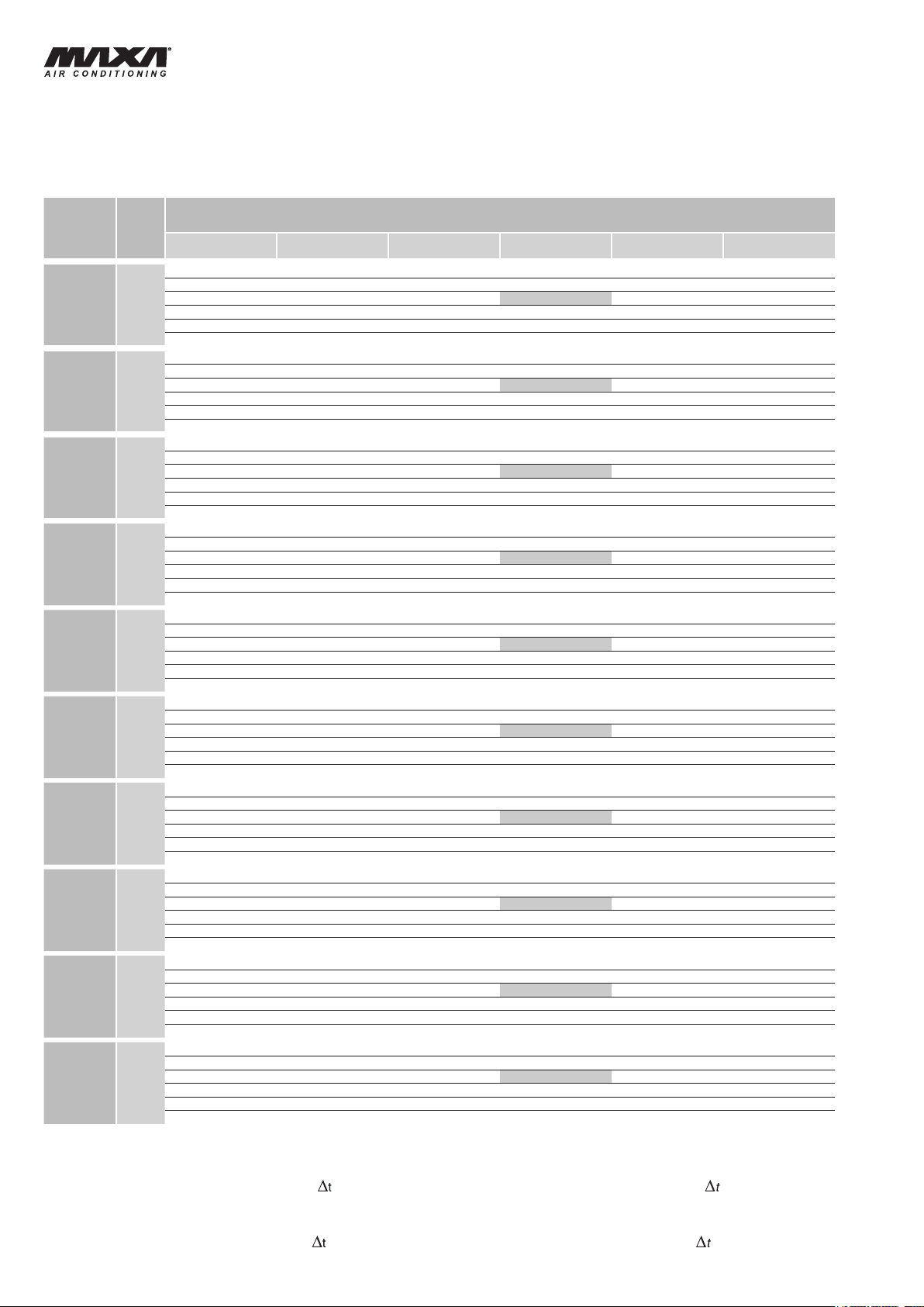
RESE IN RAFFREDDAMENTO
KÄLTELEISTUNGEN
MOD.
15
18
21
25
31
41
51
61
71
81
To (°C)
5
6
7
8
9
10
5
6
7
8
9
10
5
6
7
8
9
10
5
6
7
8
9
10
5
6
7
8
9
10
5
6
7
8
9
10
5
6
7
8
9
10
5
6
7
8
9
10
5
6
7
8
9
10
5
6
7
8
9
10
25 28 32 35 40 45
kWf kWe kWf kWe kWf kWe kWf kWe kWf kWe kWf kWe
4,4 1,2 4,3 1,3 4,1 1,3 3,9 1,4 3,6 1,6 3,4 1,8
4,6 1,2 4,4 1,3 4,2 1,3 4,1 1,4 3,8 1,6 3,5 1,8
4,8 1,3 4,6 1,3 4,4 1,3 4,2 1,4 3,9 1,6 3,6 1,8
4,9 1,3 4,7 1,3 4,5 1,4 4,3 1,5 4,0 1,6 3,7 1,8
5,0 1,3 4,9 1,4 4,7 1,4 4,5 1,5 4,2 1,6 3,9 1,8
5,6 1,3 5,0 1,4 4,8 1,4 4,6 1,5 4,3 1,7 4,0 1,8
5,4 1,5 5,2 1,6 5,0 1,6 4,8 1,7 4,4 1,9 4,1 2,1
5,6 1,5 5,4 1,6 5,1 1,6 4,9 1,7 4,6 1,9 4,2 2,1
5,8 1,5 5,6 1,6 5,3 1,6 5,1 1,7 4,7 1,9 4,3 2,2
5,9 1,5 5,7 1,6 5,5 1,6 5,3 1,8 4,9 2,0 4,5 2,2
6,0 1,6 5,9 1,6 5,7 1,7 5,4 1,8 5,0 2,0 4,7 2,2
6,8 1,6 6,1 1,7 5,9 1,7 5,6 1,8 5,2 2,0 4,9 2,2
6,8 1,8 6,5 1,9 6,2 2,0 6,0 2,1 5,6 2,4 5,1 2,6
7,0 1,8 6,8 2,0 6,4 2,0 6,2 2,1 5,7 2,4 5,3 2,6
7,2 1,9 7,0 2,0 6,7 2,0 6,4 2,1 5,9 2,4 5,4 2,7
7,5 1,9 7,2 2,0 6,9 2,0 6,6 2,2 6,1 2,4 5,7 2,7
7,6 1,9 7,5 2,0 7,1 2,0 6,8 2,2 6,3 2,4 5,9 2,7
8,6 1,9 7,7 2,0 7,4 2,1 7,0 2,2 6,5 2,5 6,1 2,7
7,9 2,1 7,7 2,3 7,3 2,3 7,0 2,5 6,5 2,8 6,0 3,1
8,2 2,2 7,9 2,3 7,5 2,4 7,2 2,5 6,7 2,8 6,2 3,1
8,5 2,2 8,2 2,4 7,8 2,4 7,5 2,5 6,9 2,8 6,4 3,2
8,7 2,2 8,4 2,4 8,1 2,4 7,8 2,6 7,2 2,9 6,6 3,2
8,9 2,3 8,7 2,4 8,3 2,4 8,0 2,6 7,4 2,9 6,9 3,2
10,0 2,3 9,0 2,4 8,6 2,5 8,2 2,6 7,7 2,9 7,2 3,2
9,1 2,5 8,8 2,6 8,4 2,7 8,1 2,9 7,5 3,2 6,9 3,6
9,4 2,5 9,1 2,7 8,6 2,7 8,3 2,9 7,7 3,3 7,1 3,6
9,7 2,6 9,4 2,7 8,9 2,7 8,6 2,9 8,0 3,3 7,3 3,7
10,0 2,6 9,7 2,7 9,2 2,8 8,9 3,0 8,3 3,3 7,6 3,7
10,2 2,6 10,0 2,8 9,5 2,8 9,2 3,0 8,5 3,4 7,9 3,7
11,5 2,6 10,3 2,8 9,9 2,8 9,4 3,0 8,8 3,4 8,2 3,7
11,0 3,0 10,6 3,2 10,1 3,2 9,7 3,5 9,0 3,9 8,3 4,4
11,4 3,0 11,0 3,2 10,5 3,3 10,0 3,5 9,3 3,9 8,6 4,4
11,8 3,1 11,4 3,3 10,8 3,3 10,4 3,5 9,6 4,0 8,9 4,4
12,1 3,1 11,7 3,3 11,2 3,3 10,8 3,6 10,0 4,0 9,2 4,4
12,3 3,2 12,1 3,3 11,5 3,4 11,1 3,6 10,3 4,0 9,6 4,5
13,9 3,2 12,5 3,4 11,9 3,4 11,4 3,7 10,6 4,1 9,9 4,5
12,9 3,3 12,5 3,6 11,9 3,6 11,4 3,9 10,6 4,4 9,8 4,9
13,3 3,4 12,9 3,6 12,3 3,7 11,8 3,9 10,9 4,4 10,0 4,9
13,8 3,5 13,3 3,7 12,7 3,7 12,2 4,0 11,3 4,4 10,4 4,9
14,2 3,5 13,7 3,7 13,1 3,8 12,6 4,0 11,7 4,5 10,8 5,0
14,4 3,6 14,2 3,8 13,5 3,8 13,0 4,1 12,1 4,5 11,2 5,0
16,3 3,6 14,6 3,8 14,0 3,8 13,4 4,1 12,5 4,6 11,6 5,0
16,2 4,2 15,6 4,5 14,9 4,5 14,3 4,9 13,3 5,5 12,2 6,1
16,7 4,3 16,2 4,5 15,4 4,6 14,8 4,9 13,7 5,5 12,6 6,2
17,3 4,3 16,7 4,6 15,9 4,6 15,3 5,0 14,2 5,6 13,0 6,2
17,8 4,4 17,2 4,6 16,4 4,7 15,8 5,1 14,7 5,6 13,6 6,2
18,1 4,5 17,8 4,7 17,0 4,7 16,3 5,1 15,1 5,7 14,1 6,3
20,5 4,5 18,4 4,7 17,6 4,8 16,8 5,2 15,6 5,8 14,6 6,3
19,7 5,0 19,0 5,3 18,1 5,5 17,4 5,9 16,2 6,6 14,9 7,4
20,3 5,1 19,7 5,5 18,7 5,5 18,0 5,9 16,7 6,6 15,3 7,4
21,0 5,2 20,3 5,5 19,3 5,6 18,6 6,0 17,2 6,7 15,8 7,5
21,7 5,2 20,9 5,6 20,0 5,7 19,2 6,1 17,9 6,7 16,5 7,5
22,0 5,3 21,7 5,7 20,6 5,7 19,9 6,1 18,4 6,8 17,1 7,6
24,9 5,4 22,3 5,7 21,4 5,8 20,4 6,2 19,0 6,9 17,7 7,6
21,7 5,5 21,0 5,9 19,9 6,0 19,2 6,4 17,8 7,3 16,4 8,1
22,4 5,6 21,7 6,0 20,6 6,1 19,8 6,5 18,4 7,3 16,9 8,1
23,2 5,7 22,4 6,1 21,3 6,1 20,5 6,6 19,0 7,4 17,5 8,2
23,9 5,8 23,1 6,1 22,0 6,2 21,2 6,7 19,7 7,4 18,2 8,3
24,2 5,9 23,9 6,2 22,7 6,3 21,9 6,7 20,3 7,5 18,9 8,3
27,4 5,9 24,6 6,2 23,5 6,3 22,5 6,8 21,0 7,6 19,6 8,4
COOLING CAPACITY
PUISSANCE FRIGORIFIQUE
TEMPERATURA ARIA ESTERNA °C / AMBIENT AIR TEMPERATURE °C
UMGEBUNGSTEMPERATUR °C / TEMPERATURE AIR EXTERIEUR °C
kWf: Potenzialità frigorifera (kW).
kWe: Potenza assorbita (kW).
To: Temperatura acqua in uscita evaporatore ( ingr./usc.=5 K).
kWf: Kälteleistung (kW).
kWe: Leistungsaufnahme (kW).
To: Wassertemperatur am Verdampferaustritt ( Ein/Austritt =5 K).
8
kWf: Cooling capacity (kW).
kWe: Power input (kW).
To: Evaporator leaving water temperature ( in./out =5 K).
kWf: Puissance frigorique (kW).
kWe: Puissance absorbée (kW).
To: Temperature sortie eau évaporateur ( entrée/sortie =5 K).
Page 9
HWAL-A 15÷81
R410A
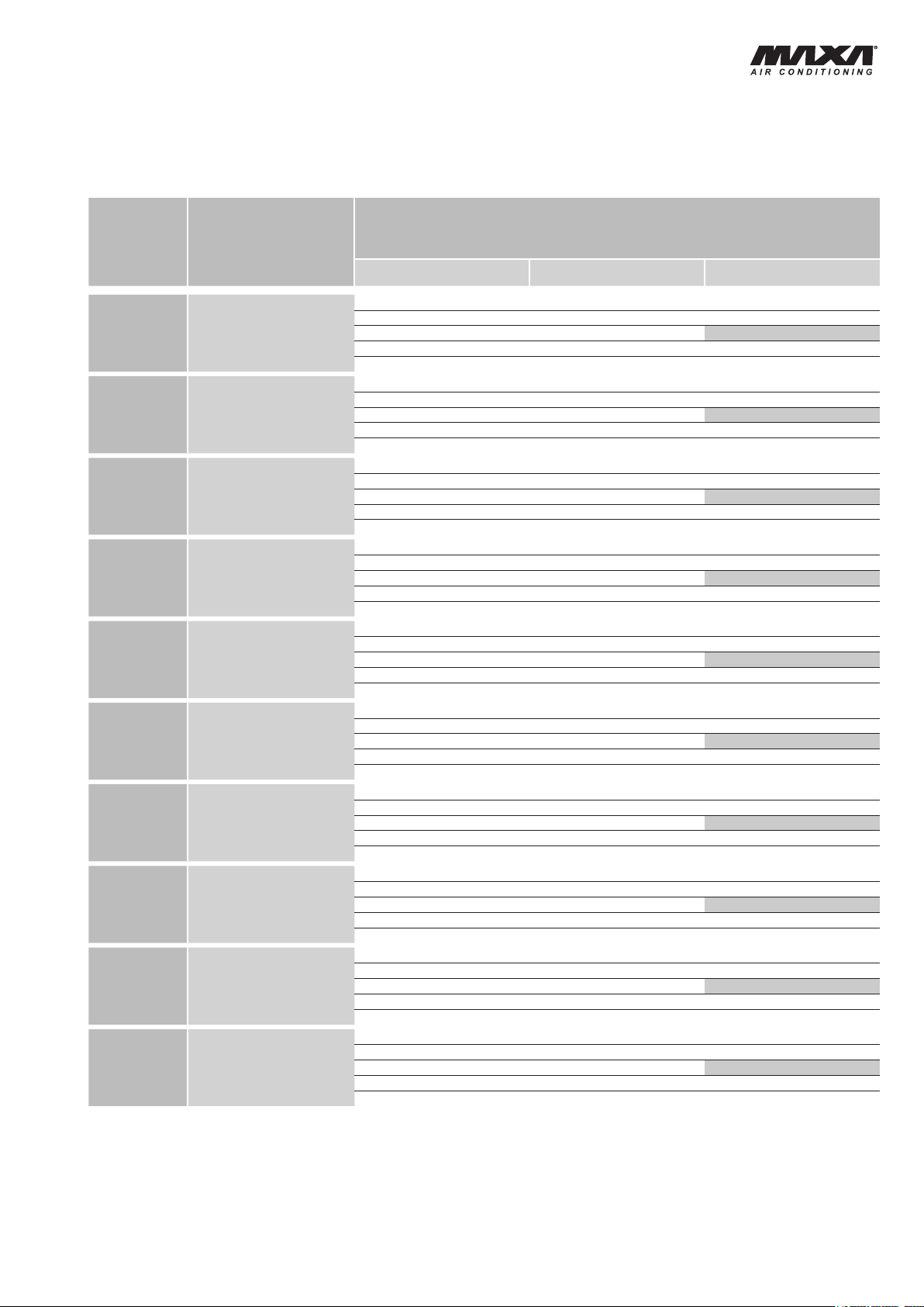
RESE IN RISCALDAMENTO
HEIZLEISTUNGEN
MOD.
Ta (°C) RH(%)
0 90
5 90 5,0 1,4 4,9 1,5 4,9 1,7
15
18
21
25
31
41
51
61
71
81
7 87 5,2 1,4 5,1 1,5 5,0 1,7
10 70 5,5 1,4 5,4 1,5 5,3 1,7
15 60
0 90
5 90 6,0 1,6 5,9 1,8 5,8 2,0
7 87
10 70
15 60
0 90
5 90 8,0 2,1 7,9 2,3 7,8 2,6
7 87 8,3 2,1 8,2 2,3 8,0 2,6
10 70 8,8 2,1 8,7 2,3 8,5 2,6
15 60
0 90
5 90 8,7 2,3 8,6 2,6 8,4 2,9
7 87 9,0 2,3 8,9 2,6 8,7 2,9
10 70 9,6 2,3 9,4 2,6 9,3 2,9
15 60
0 90
5 90 10,3 2,8 10,2 3,1 10,0 3,5
7 87 10,7 2,8 10,5 3,1 10,3 3,5
10 70 11,3 2,8 11,1 3,1 11,0 3,5
15 60
0 90
5 90 12,5 3,3 12,2 3,8 12,0 4,2
7 87 12,9 3,3 12,6 3,8 12,4 4,2
10 70 13,7 3,3 13,4 3,8 13,2 4,2
15 60
0 90
5 90 14,9 3,8 14,6 4,3 14,4 4,8
7 87 15,4 3,8 15,1 4,3 14,8 4,8
10 70 16,3 3,8 16,0 4,3 15,8 4,8
15 60
0 90
5 90 18,9 4,9 18,5 5,6 18,3 6,2
7 87
10 70 20,7 4,9 20,3 5,6 20,1 6,2
15 60
0 90
5 90 22,0 5,6 21,6 6,4 21,3 7,1
7 87 22,7 5,6 22,3 6,4 21,9 7,1
10 70 24,1 5,6 23,7 6,4 23,4 7,1
15 60
0 90
5 90 24,5 6,3 24,0 7,2 23,7 8,0
7 87
10 70
15 60
HEATING CAPACITY
PUISSANCE CALORIFIQUE
TEMPERATURA ACQUA INGRESSO/USCITA CONDENSATORE °C
CONDENSER INLET/OUTLET WATER TEMPERATURE °C
WASSERTEMPERATUR AM VERFLÜSSIGEREIN-AUSTRITT °C
TEMPERATURE DE L’EAU ENTREE/SORTIE AU CONDENSEUR °C
30/35 35/40 40/45
kWt kWe kWt kWe kWt kWe
4,5 1,4 4,4 1,5 4,4 1,7
6,0 1,4 5,9 1,5 5,8 1,7
5,4 1,6 5,3 1,8 5,2 2,0
6,2 1,6 6,1 1,8 6,0 2,0
6,6 1,6 6,5 1,8 6,4 2,0
7,2 1,6 7,1 1,8 7,0 2,0
7,2 2,1 7,1 2,3 7,0 2,6
9,7 2,1 9,5 2,3 9,3 2,6
7,9 2,3 7,7 2,6 7,6 2,9
10,5 2,3 10,3 2,6 10,2 2,9
9,3 2,8 9,1 3,1 9,0 3,5
12,4 2,8 12,2 3,1 12,0 3,5
11,2 3,3 11,0 3,8 10,8 4,2
15,0 3,3 14,7 3,8 14,5 4,2
13,4 3,8 13,1 4,3 12,9 4,8
17,9 3,8 17,5 4,3 17,3 4,8
17,0 4,9 16,6 5,6 16,4 6,2
19,5 4,9 19,2 5,6 18,8 6,2
22,7 4,9 22,2 5,6 22,0 6,2
19,8 5,6 19,4 6,4 19,1 7,1
26,4 5,6 25,9 6,4 25,6 7,1
22,1 6,3 21,6 7,2 21,2 8,0
25,3 6,3 24,9 7,2 24,4 8,0
26,9 6,3 26,4 7,2 26,0 8,0
29,4 6,3 28,9 7,2 28,5 8,0
Ta: Temperatura aria esterna a bulbo secco (°C).
RH: Umidità relativa aria esterna (%).
kWt: Potenzialità termica (kW).
kWe: Potenza assorbita (kW).
Ta: Externerlufttemperatur d.b. (°C).
RH: Relative Externerluftfeuchtigkeit (%).
kWt: Heizleistung (kW).
kWe: Leistungsaufnahme (kW).
Ta: Ambient air temperature dry bulb (°C).
RH: Ambient air relative humidity (%).
kWt: Heating capacity (kW).
kWe: Power input (kW).
Ta: Température air extérieure à bulbe sec (°C).
RH: Humidité relative à l'air extérieure (%).
kWt: Puissance termique (kW).
kWe: Puissance absorbée (kW).
9
Page 10
HWAL-A 15÷81
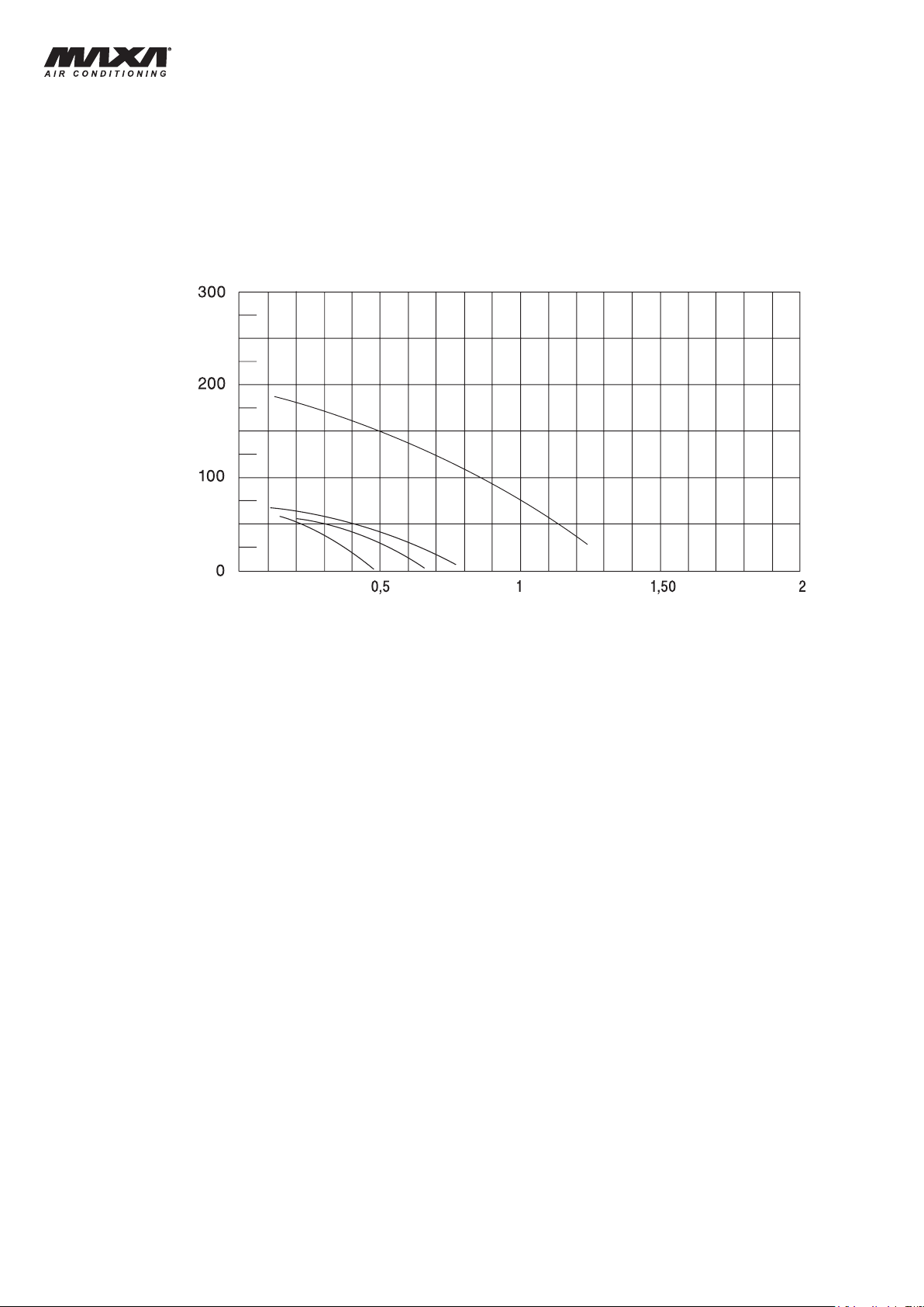
Prevalenza utile
Available static pressure
Externe statische Pressung
Pression utile disponible
(kPa)
Portata acqua / Water flow / Wasserdurchfluß / Débit d'eau
(l/s)
15-18-21
25-31
41
51-61-71-8
1
PREVALENZA UTILE POMPA DI
CIRCOLAZIONE
EXTERNE STATISCHE PRESSUNG
DER UMLAUFPUMPE
CIRCULATION PUMP
AVAILABLE STATIC PRESSURE
PRESSION UTILE DE LA POMPE
DE CIRCULATION
CALCOLO PREVALENZA UTILE POMPA
DI CIRCOLAZIONE
ESEMPIO:
Si supponga di voler ricavare la prevalenza utile della pompa su
un gruppo frigorifero HWAL-A 51 alle condizioni nominali (acqua
in/out 12/7 °C, aria esterna 35 °C):
Resa frigorifera: 12,2 kW;
Portata acqua : (12,2x860/5/3600)=0,58 l/s;
Prevalenza utile pompa: 140 kPa.
BERECHNUNG DER EXTERNEN STATISCHEN
PRESSUNG DER UMLAUFPUMPE
BEISPIEL:
Man nimmt an, man will die externe statische Pressung der Pumpe
in einen Kaltwassersatz HWAL-A 51 unter den Nennbedingungen
(Wasserein/austritt 12/7 °C, Umgebungstemperatur 35 °C)
berechnen:
Kälteleistung: 12,2 kW;
Wasserdurchfluß : (12,2x860/5/3600)=0,58 l/s;
Externe statische Pressung der Pumpe: 140 kPa.
CIRCULATION PUMP AVAILABLE HEAD
PRESSURE CALCULATION
EXAMPLE:
The available pump head pressure can be obtained as follows,
considering a HWAL-A 51 at the nominal conditions (water in/out
12/7 °C, ambient temperature 35 °C):
Cooling capacity: 12,2 kW;
Water ow : (12,2x860/5/3600)=0,58 l/s;
Pump available static pressure: 140 kPa.
CALCUL DE LA PRESSION DISPONIBLE DE LA
POMPE DE CIRCULATION
EXEMPLE:
On suppose vouloir déterminer la pression disponible de la pompe
à eau sur unité HWAL-A 51 aux conditions nominales (eau entrèe/
sortie 12/7 °C, air extérieur 35 °C):
Puissance frigorique: 12,2 kW;
Débit d’eau : (12,2x860/5/3600)=0,58 l/s;12,2x860/5/3600)=0,58 l/s;x860/5/3600)=0,58 l/s;
Pression utile pompe: 140 kPa.
10
Page 11
HWAL-A 15÷81
COEFFICIENTI CORRETTIVI PER FATTORI DI
FOULING FACTOR CORRECTIONS
SPORCAMENTO
KORREKTURKOEFFIZIENTEN FÜR
VERSCHMUTZUNGSFAKTOREN
Fattori di sporcamento evaporatore (m²°C/W)
Verschmutzungsfaktoren Verdampfer (m²°C/W)
f1 fp1
0 Piastre pulite / Clean plate exchanger 1 1 0
0,44 x 10
0,88 x 10
1,76 x 10
f1: fattori di correzione per la potenza resa;
fp1: fattori di correzione per la potenza assorbita dal compressore.
Le prestazioni delle unità indicate nelle tabelle vengono fornite per le
condizioni di scambiatore pulito (fattore di sporcamento = 0). Per valori
differenti del fattore d’incrostazione, le prestazioni fornite dovranno
essere corrette con i fattori indicati.
-4
-4
-4
0,98 0,99 0,44 x 10
0,96 0,99 0,88 x 10
0,93 0,98 1,76 x 10
COEFFICIENTS CORRECTEURS POUR
FACTEURS D’ENCRASSEMENTS
Evaporator fouling factors (m²°C/W)
Facteure d’encrassemente evaporateur (m²°C/W)
f1: capacity correction factors;
fp1: compressor power input correction factor.
Unit performances reported in the tables are given for the condition of
clean exchanger (fouling factor = 0). For different fouling factors values,
unit performances should be corrected with the correction factors shown
above.
Sauberer Wärmetauscher / Echangeur propre
-4
-4
-4
f1: Korrekturfaktoren für Kälteleistung bzw. Verflüssigerleistung;
fp1: Korrekturfaktoren für Leistungsaufnahme von dem Verdichter.
Die in der Tabelle angeführten Geräteleistungen sind für die Bedingung
eines sauberen Wärmetauschers angegeben (Verschmutzungfaktor = 0).
Bei unterschiedlichen Werten des Verschmutzungsfaktors müssen die
Leistungen mit den angegebenen Faktoren korrigiert werden.
LIMITI DI FUNZIONAMENTO
Temperatura acqua in ingresso °C
Temperatura acqua in uscita °C 5 15 30 50 Outlet water temperature
Salto termico acqua °C 3 9 3 10 Water thermal difference
Temperatura aria esterna °C -20 46 -10 20 Ambient air temperature
Minima temperatura dell’acqua
refrigerata con l’impiego di glicole
Max pressione di esercizio lato
acqua scambiatore
EINSATZBEREICH
Wassereintrittstemperatur °C
Wasseraustrittstemperatur °C 5 15 30 50 Température eau sortie
Wassertemperaturdifferenz °C 3 9 3 10 Ecart de température
Umgebungstemperatur °C -20 46 -10 20 Température air extérieur
Min. Temperatur des gekühlten
Wasser mit Verwendung von Glykol
Max. Betriebsdruck
Wärmetauscher- Wasser-Seite
kPa
Raffreddamento / Cooling Riscaldamento / Heating
min max min max
8 20 25 45
°C -8 ---
kPa
Kühlung / Refroidissement Heizung / Chauffage
min max min max
8 20 25 45
°C -8 ---
f1: Facteurs de correction pour la puissance rendue;
fp1:
Facteurs de correction pour la puissance absorbée du compresseur.
Les performances des unités indiquées dans les tableaux sont données
pour la condition d’échangeur propre (facteur d'encrassement = 0). Pour
des valeurs différentes du facteur d’encrassements, les performances
annoncées seront corrigées en utilisant les facteurs indiqués.
OPERATING RANGE
Inlet water temperature
Minimun chilled water outlet
temperature with glycol mixture
300
Max operating pressure heat
exchanger water side
LIMITES DE
FONCTIONNEMENT
Température eau entrée
Température minimum de l'eau glacée
avec glycol
300
Pression maximun d’utilisation
échangeur côte eau
11
Page 12
HWAL-A 15÷81
MC
CA
SPL
MV
SPH
VT
FD
TRGV
ST2
EW
PD
ST1
VSI
MP
ST
MN
VE
CAR
SC
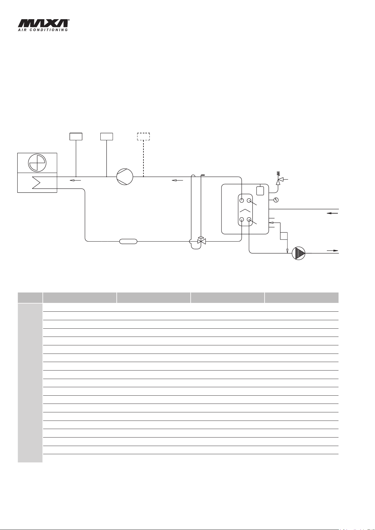
SCHEMA CIRCUITO FRIGORIFERO E IDRAULICO UNITA'
PER SOLO RAFFREDDAMENTO
HYDRAULISCHER ANSCHLUß UND KÄLTESCHEMA DER
KALTWASSERSÄTZE
REFRIGERANT AND HYDRAULIC CHILLER CIRCUIT
DIAGRAM
SCHEMAT DU CIRCUIT HYDRAULIQUE ET FRIGORIFIQUE
GROUPE DE PRODUCTION D’EAU GLACÉE
CA
CAR
EW
FD
MC
MN
MP
MV
PD
SC
SPH
SPL
ST
ST1
ST2
TRGV
VE
VSI
VT
DENOMINAZIONE DESIGNATION BEZEICHNUNG DESIGNATION
BATTERIA CONDENSANTE CONDENSING COIL VERFLUSSIGER/VERDAMPFER BATTERIE COND.
CARICO LOAD LAST CHARGE
EVAPORATORE
FILTRO DISIDRATATORE
COMPRESSORE
MANOMETRO ACQUA
ELETTROPOMPA
ELETTROVENTILATORE
PRESSOSTATO DIFFERENZIALE
SCARICO ACQUA WATER DRAIN WASSER ENTLADEN VIDANGE D'EAU
PRESSOSTATO ALTA MAN.
PRESSOSTATO BASSA AUT. (accessorio) LOW PRESS. SWITCH A.R. (accessory) NIEDERDRUCKSCHALT. AUT. (Zubehör)
SERBATOIO
SONDA DI LAVORO
SONDA ANTIGELO
TRASDUTTORE DI PRESSIONE
VASO DI ESPANSIONE
VALVOLA DI SICUREZZA 300 kPa
VALVOLA D'ESPANSIONE
EVAPORATOR
FILTER DRIER
COMPRESSOR
WATER GAUGE
ELECTRICAL PUMP
ELECTRIC FAN MOTOR
DIFFERENTIAL PRESSURE SWITCH
HIGH PRESS.SWITCH M.R.
STORAGE TANK
WORKING PROBE
ANTIFREEZE PROBE
PRESSURE TRANSDUCER
EXPANSION VESSEL
SAFETY WATER VALVE 300 kPa
EXPENSION VALVE
VERDAMPFER EVAPORATEUR
TROCKNERFILTER
VERDICHTER
WASSER MANOMETER
ELEKTRISCHE PUMPE
ELEKTROVENTILATOR
DIFFERENZDRUCKSCALTER
HOCHDRUCKSCHALTERMAN
SPEICHERBEHÄLTER
WASSERTEMP. -FÜHLER
FROSTSCHUTZFÜHLER
DRUCKGEBER
AUSDEHNUNGSGEFÄß
SICHERHEITSVENTIL 300 kPa
EXPANSIONSVENTIL
BENUTZERSEITE
FILTRE DESHYDRATEUR
COMPRESSEUR
MANOMÈTRE EAU
POMPE ELECTRIQUE
VANNE THERMOSTATIQUE
PRESSOSTAT DIFFERENTIEL
PRSS. HAUTE PRESS. MAN.
PRESS. BASSE PRESS. AUT. (accessoire)
BALLON TAMPON
SONDE DU TRAVAIL
SONDE ANTIGEL
TRANSDUCTEUR DE PRESS
VASE D’EXPANSION
VANNE DE SECURITEE EAU 300 kPa
SOUPAPE D'EXPANSION
12
Page 13
HWAL-A 15÷81
MC
CEC
SPL
MV
SPH
VT
FD
RCV
VT
CV
CV
TRGV
LR
VSI1
MP
EW
ST
ST2
PD
VE
ST1
MN
VSI
CAR
SC
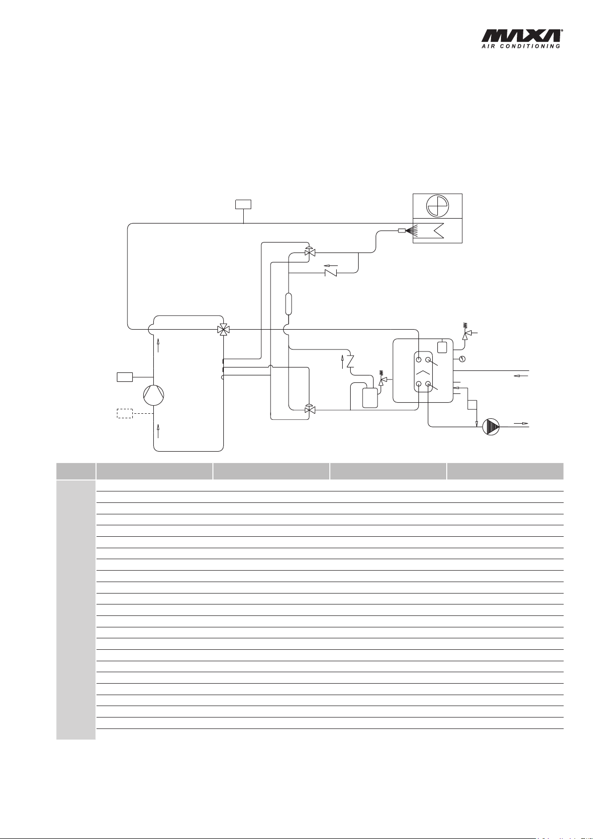
SCHEMA CIRCUITO FRIGORIFERO E IDRAULICO UNITA'
A POMPA DI CALORE
HYDRAULISCHER ANSCHLUß UND KÄLTESCHEMA DER
WÄRMEPUMPE VERSION
REFRIGERANT AND HYDRAULIC CIRCUIT DIAGRAM
UNIT IN HEAT PUMP VERSION
SCHEMAT DU CIRCUIT HYDRAULIQUE ET FRIGORIFIQUE
UNITÉ À POMPE À CHALEUR
CAR
CEC
CV
EW
FD
LR
MC
MN
MP
MV
PD
RCV
SC
SPH
SPL
ST
ST1
ST2
TRGV
VE
VSI
VSI1
VT
DENOMINAZIONE
CARICO
BATTERIA CONDENSANTE-EVAPORANTE
VALVOLA DI RITEGNO ONE WAY VALVE RÜCKSCHLAGVENTIL VANNE DE RETENTION
EVAPORATORE EVAPORATOR VERDAMPFER EVAPORATEUR
FILTRO DISIDRATATORE FILTER DRIER TROCKNERFILTER FILTRE DESHYDRATEUR
RICEVITORE DI LIQUIDO LIQUID RECEIVER FLÜSSIGKEITSSAMMLER RESERVOIR DE LIQUIDE
COMPRESSORE COMPRESSOR VERDICHTER COMPRESSEUR
MANOMETRO ACQUA WATER GAUGE WASSER MANOMETER MANOMÈTRE EAU
ELETTROPOMPA ELECTRICAL PUMP ELEKTRISCHE PUMPE POMPE ELECTRIQUE
ELETTROVENTILATORE ELECTRIC FAN MOTOR ELEKTROVENTILATOR ELECTROVENTILATEUR
PRESSOSTATO DIFFERENZIALE DIFFERENTIAL PRESSURE SWITCH DIFFERENZDRUCKSCALTER PRESSOSTAT DIFFERENTIEL
VALVOLA 4 VIE 4 WAY VALVE VIERWEGE-UMSCHALTVENTIL VANNE 4 VOIES
SCARICO ACQUA
PRESSOSTATO ALTA MAN. HIGH PRESS.SWITCH M.R. HOCHDRUCKSCHALTERMAN PRSS. HAUTE PRESS. MAN.
PRESSOSTATO BASSA AUT. (accessorio) LOW PRESS. SWITCH A.R. (accessory) NIEDERDRUCKSCHALT. AUT. (Zubehör)
SERBATOIO STORAGE TANK SPEICHERBEHÄLTER BALLON TAMPON
SONDA DI LAVORO WORKING PROBE WASSERTEMP. -
SONDA ANTIGELO ANTIFREEZE PROBE
TRASDUTTORE DI PRESSIONE PRESSURE TRANSDUCER DRUCKGEBER TRANSDUCTEUR DE PRESS
VASO DI ESPANSIONE EXPANSION VESSEL AUSDEHNUNGSGEFÄß VASE D’EXPANSION
VALVOLA DI SICUREZZA 300 kPa SAFETY VALVE 300 kPa SICHERHEITSVENTIL 300 kPa SOUPAPE DE SECURITE 300 kPa
VALVOLA DI SICUREZZA SAFETY VALVE SICHERHEITSVENTIL SOUPAPE DE SECURITE
VALVOLA D'ESPANSIONE EXPANSION VALVE EXPANSIONSVENTIL SOUPAPE D'EXPANSION
DESIGNATION
LOAD
CONDENSING-EVAPORATING COIL
WATER DRAIN
BEZEICHNUNG
LAST CHARGE
VERFLÜSSIGER/VERDAMPFERREGISTER BATTERIE CONDENSANTE-EVAPORANTE
FÜHLER
WASSER ENTALDEN VIDANGE D'EAU
FROSTSCHUTZFÜHLER BNUTZERSEITE
DESIGNATION
PRESS. BASSE PRESS. AUT. (accessoire)
SONDE DU TRAVAIL
SONDE ANTIGEL
13
Page 14

HWAL-A 15÷81
UTILIZZO DI MISCELE ACQUA/GLICOLE
ETILENICO
Il glicole etilenico miscelato all’acqua di circolazione viene
impiegato per prevenire la formazione di ghiaccio negli scambiatori
dei refrigeratori e nei serbatoi inseriti nei circuiti idraulici.
L’ impiego di miscele a basso punto di congelamento produce
una variazione delle principali caratteristiche termodinamiche
delle unità. I parametri che interessano, in quanto di impiego
comune, sono i seguenti:
- resa frigorifera
- potenza assorbita compressore
- portata della miscela
- prevalenza utile
Per semplicità si riassumono in una tabella i valori dei coefficienti
correttivi per le percentuali aggiuntive di glicole etilenico di uso
comune.
Percentuale di glicole etilenico in
peso (%)
Temp.di congelamento (°C)
Coefficiente correttivo resa frigorifera 1 0,975 0,95 0,93 0,91 0,88 Cooling capacity correction factor
Coeff.corr. potenza assorbita compressore 1 1,01 0,995 0,990 0,985 0,975 Compressor absorbed power corr. factor
Coefficiente correttivo portata miscela 1 1,01 1,04 1,08 1,14 1,20 Mixture ow correction factor
Coefficiente correttivo prevalenza utile
0 10 20 30 40 50
0 -4,5 -9,5 -15,5 -21,5 -32,5
1 0,96 0,95 0,92 0,84 0,78
OPERATION WITH ETHYLENE GLYCOL
MIXTURES
The use of ethylene glycol mixtures is intended to prevent freezing
in chillers heat exchanger and tanks.
The use of low freezing point mixtures causes a modication
in the thermodynamic properties of the units. The major
parameters affected by the use of glycol mixtures are the
following:
- cooling capacity
- compressor absorbed power
- mixture ow
- available static pressure
In the table below are reported the correction factors referred
to the most common ethylene glycol mixtures.
Ethylene glycol percent by weight
(%)
Freezing point ( °C)
Available static presseure correction factor
ESEMPIO DI CALCOLO
Si fornisce un esempio di calcolo per interpretare in maniera
corretta i coefficienti riportati in tabella.
Si supponga di dover operare su un refrigeratore d’acqua HWAL-A
51 le cui prestazioni alle condizioni nominali siano le seguenti:
Resa frigorifera: 12,2 kW
Potenza assorbita compressore: 3,7 kW
Portata acqua: 0,58 l/s
Prevalenza utile: 140 kPa
Con l’aggiunta del 20% di glicole tali grandezze assumeranno i
seguenti valori, facendo uso dei coefficienti riportati in tabella:
Resa frigorifera: 12,2 x 0,950 = 11,6 kW
Potenza assorbita compressore: 3,7 x 0,995 = 3,68 kW
Portata acqua: 0,58 x 1,04 = 0,60 l/s
Dalla curva delle perdite di carico si ricava la prevalenza utile
corrispondente al nuovo valore della portata (0,60 l/s ==> 137 kPa).
La prevalenza utile corretta relativa ad una miscela di glicole al
20% sarà dunque:
Prevalenza utile: 137 x 0,95 = 130 kPa.
CALCULATION EXAMPLE
An example can help to use properly the coefcients reported
in the table.
Suppose that a water chiller the HWAL-A 51 presents the following
performances at the nominal working conditions:
Cooling capacity: 12,2 kW
Compressor absorbed power: 3,7 kW
Water ow: 0,58 l/s
Available static pressure: 140 kPa
With 20% glycol mixture these parameters will change to the
following values, according to the correction factors:
Cooling capacity: 12,2 x 0,950 = 11,6 kW
Compressor absorbed power: 3,7 x 0,995 = 3,68 kW
Mixture ow: 0,58 x 1,04 = 0,60 l/s
From the available static pressure the value corresponding to
the new mixture ow (0,60 l/s ==>137 kPa) can be read.
The correct available static pressure corresponding to a 20%
glycol mixture will be:
Available static pressure: 137 x 0,95 = 130 kPa.
14
Page 15

HWAL-A 15÷81
VERWENDUNG VON
WASSER/ETHYLENGLIKOL-MISCHUNGEN
Die Verwendung von Ethylenglykol-Wassergemisch ist
empfohlen, um die Eisbildung an den Wärmetauschern und
Speichern der Kaltwassersätze zu vermeiden.
Die Verwendung von Mischungen mit niedrigem Gefrierpunkt
bewirkt eine Änderung der wichtigsten thermodynamischen
Betriebseigenschaften der Geräte. Die Parameter von besonderer
Bedeutung bei Verwendung dieser Mischungen sind folgende:
- Kälteleistung
- Verdichter Leistungsaufnahme
- Mischungsdurchfluß
- Ext. statische Pressung
In der unten stehenden Tabelle sind die Werte der
Korrekturkoeffizienten bezüglich der normalgebräuchlichen
Äthylenglykolmischungen dargestellt.
Glykol-Prozent pro
Gewicht (%)
Gefriertemperatur (°C)
Korr.-koeff. Kälteleistung 1 0,975 0,95 0,93 0,91 0,88 Coeff. corr. puissance frigorique
Korr.-koeff. Verdichter Leistungsaufnahme 1 1,01 0,995 0,990 0,985 0,975
Korr.-koeff. Mischungsdurchfluß 1 1,01 1,04 1,08 1,14 1,20 Coeff. correcteur débit solution
Korr.-koeff. Ext. statische Pressung
0 10 20 30 40 50
0 -4,5 -9,5 -15,5 -21,5 -32,5
1 0,96 0,95 0,92 0,84 0,78
UTILISATION DE LA SOLUTION EAU/GLYCOL
ETHYLENIQUE
Le glycol éthylènique mélangé à l’eau d’utilisation est employé pour
prévenir la formation de la glace dans les échangeurs et ballons
des groupes, insérés dans les circuits hydrauliques.
L’emploi de cette solution à bas point de congélation produit une
variation des principales caractéristiques thermodynamiques
de fonctionnement de la machine. Les paramètres affectés par
l’utilisation de glycol sont les suivants :
- puissance frigorique
- puissance absorbée compresseur
- débit de la solution
- Pression utile
A cet effet, sont récapitulés dans le tableau ci-dessous les
valeurs des coefcients de correction pour les pourcentages
d’ adjonction de gl ycol éth ylènique d’utilisation plus
commune.
Pourcentage de glycol en poids
(%)
Température de congélation (°C)
Coeff. corr. puissance absorbée compresseur
Coeff. corr. pression utile
BERECHNUNGSBEISPIEL
Ein Beispiel kann Ihnen helfen, um die oben stehenden
Koeffizienten korrekt zu interpretieren:
Man nehme an, man muß einen Kaltwassersatz HWAL-A 51
einsetzen, dessen Leistungen unter Nennbedingungen die
folgenden sind:
Kälteleistung: 12,2 kW
Verdichter Leistungsaufnahme: 3,7 kW
Wasserdurchfluß: 0,58 l/s
Ext. statische Pressung: 140 kPa
Mit einem Zusatz von 20% Glykol und unter Verwendung der oben
angeführten Koeffizienten, ändern sich diese Werte wie folgt:
Kälteleistung: 12,2 x 0,950 = 11,6 kW
Verdichter Leistungsaufnahme: 3,7 x 0,995 = 3,68 kW
Mischungsdurchfluß: 0,58 x 1,04 = 0,60 l/s
Von der Druckverlust-Kurve kann der dem neuen Durchflußwert
entsprechende Ext. statische Pressung (0,60 l/s ==> 137 kPa)
abgelesen werden.
Der korrekte Ext. statische Pressung bezüglich einer 20%
Glykolmischung wird also sein:
EXEMPLE DE CALCULATION
Pour utiliser correctement les coefcients indiqués dans le
tableau, voici un exemple pratique. On suppose vouloir intervenir
sur un groupe d’eau glacée HWAL-A 51 dont les conditions
nominales sont les suivantes :
Puissance frigorique : 12,2 kW
Puissance absorbée compresseur: 3,7 kW
Débit d’eau : 0,58 l/s
Pression utile: 140 kPa
En ajoutant 20 % de glycol, les valeurs se modieront en
utilisant les coefcients indiqués dans le tableau :
Puissance frigorique : 12,2 x 0,950 = 11,6 kW
Puissance absorbée compresseur: 3,7 x 0,995 = 3,68 kW
Débit solution : 0,58 x 1,04 = 0,60 l/s
Sur la courbe des pertes de charge on relève la pression utile:
correspondante au valeur nouveau de débit (0,60 l/s ==> 137
kPa).
La pression utile: correcte relative a un solution de glycol de 20
% sera donc :
Ext. statische Pressung: 137 x 0,95 = 130 kPa.
Pression utile: 137 x 0,95 = 130 kPa.
15
Page 16
HWAL-A 15÷81
LIVELLI DI PRESSIONE SONORA SOUND PRESSURE LEVEL
MOD.
15
18
21
25
31
41
51
61
71
81
MOD.
15
18
21
25
31
41
51
61
71
81
BANDE D’OTTAVA\OCTAVE BANDS (Hz)
63 125 250 500 1000 2000 4000 8000
(dB) (dB) (dB) (dB) (dB) (dB) (dB) (dB)
La Lb La Lb La Lb La Lb La Lb La Lb La Lb La Lb
57,7 47,7 50,8 46,2 50,3 45,8 49,8 48,3 47,8 43,8 46,3 40,8 42,8 41,3 45,8 44,8 53,7 50,8
58,0 48,0 51,0 46,5 50,5 46,0 50,0 48,5 48,0 44,0 46,5 41,0 43,0 41,5 46,0 45,0 53,9 51,0
58,0 49,0 51,0 47,0 51,0 46,0 50,5 49,0 48,5 44,5 46,5 41,5 43,0 42,0 46,0 45,5 54,2 51,5
59,0 49,0 51,0 47,0 52,0 46,5 51,0 49,5 49,5 45,5 47,0 42,5 43,0 42,0 46,0 45,5 54,7 52,0
60,5 60,5 66,5 62,0 60,5 58,5 53,5 50,0 50,5 44,0 49,0 44,5 47,5 43,5 46,5 45,5 58,4 54,8
54,0 51,0 56,0 50,5 54,0 50,0 59,0 46,0 51,5 47,5 47,0 44,0 46,0 43,5 47,0 46,0 58,7 52,6
54,5 51,0 56,0 50,5 54,5 50,5 59,5 46,5 52,0 47,0 47,5 44,0 47,0 44,0 47,5 47,0 59,2 52,9
55,0 51,5 56,3 51,0 54,6 51,0 59,7 47,0 52,1 47,5 47,5 44,5 47,0 44,0 47,0 47,0 59,3 53,2
55,0 52,0 56,3 51,0 54,6 51,5 59,7 47,0 52,2 48,0 47,5 44,5 47,0 44,0 47,0 47,0 59,3 53,4
55,5 52,5 56,7 51,5 54,9 52,0 59,8 47,1 52,2 48,5 47,5 44,7 47,3 44,3 47,3 47,3 59,4 53,7
BANDE D’OTTAVA\OCTAVE BANDS (Hz) TOTALE
63 125 250 500 1000 2000 4000 8000
(dB) (dB) (dB) (dB) (dB) (dB) (dB) (dB)
Lc Ld Lc Ld Lc Ld Lc Ld Lc Ld Lc Ld Lc Ld Lc Ld
57,8 49,3 50,3 49,7 51,8 48,7 54,3 50,2 49,8 47,7 45,8 43,7 42,8 41,7 45,5 45,0 55,5 52,9
58,0 49,5 50,5 50,0 52,0 49,0 54,5 50,5 50,0 48,0 46,0 44,0 43,0 42,0 45,5 45,0 55,7 53,2
58,5 49,5 51,0 50,0 52,0 50,0 55,0 50,5 50,0 48,0 46,5 44,0 43,0 42,5 45,5 45,5 55,9 53,4
58,5 50,0 51,0 50,5 53,0 50,0 55,0 51,0 50,5 48,5 47,0 45,0 43,0 42,5 46,0 45,5 56,2 53,8
60,7 51,7 52,2 52,7 54,3 50,7 56,3 52,2 51,7 49,0 48,5 45,5 44,0 43,5 46,5 46,5 57,5 54,6
56,0 52,0 55,5 51,0 55,5 51,0 56,0 52,5 51,0 49,5 49,5 45,5 45,0 46,0 47,0 47,0 57,6 55,2
56,5 52,0 55,5 51,5 56,0 51,0 56,0 53,0 53,5 49,7 49,5 45,5 45,5 47,0 47,0 47,0 58,3 55,6
56,0 53,0 56,0 52,0 56,0 51,5 56,5 53,5 53,5 50,0 50,0 46,0 46,0 46,5 47,0 47,5 58,6 55,9
56,0 53,0 56,0 51,5 56,0 51,5 56,5 54,0 54,0 50,0 50,0 46,0 46,5 46,0 47,0 47,0 58,8 55,9
56,5 53,5 56,5 52,0 56,5 52,0 57,1 54,1 54,1 50,1 50,2 46,2 46,7 46,3 47,3 47,3 59,1 56,1
TOTALE
TOTAL
dB(A)
La Lb
TOTAL
dB(A)
Lc Ld
L (a, b, c, d): valori di pressione sonora rilevati in
condizioni di campo libero con fono-
metro posizionato ad 1 m dall’unità e
1,5 m da terra, nei punti in figura.
Ld
Mod. 15 - 18 - 21 - 25 - 31- 41- 51 - 61 - 71 - 81
16
L (a, b, c, d): sound pressure level measured in
free eld conditions, at 1 m from
the unit et 1,5 m from the oor level,
in the point on the picture.
La
Lb
Lc
Page 17
HWAL-A 15÷81
SCHALLDRUCKPEGEL NIVEAUX DE PRESSION SONORE
MOD.
15
18
21
25
31
41
51
61
71
81
MOD.
15
18
21
25
31
41
51
61
71
81
OKTAVBÄNDER\BANDES D'OCTAVE (Hz)
63 125 250 500 1000 2000 4000 8000
(dB) (dB) (dB) (dB) (dB) (dB) (dB) (dB)
La Lb La Lb La Lb La Lb La Lb La Lb La Lb La Lb
57,7 47,7 50,8 46,2 50,3 45,8 49,8 48,3 47,8 43,8 46,3 40,8 42,8 41,3 45,8 44,8 53,7 50,8
58,0 48,0 51,0 46,5 50,5 46,0 50,0 48,5 48,0 44,0 46,5 41,0 43,0 41,5 46,0 45,0 53,9 51,0
58,0 49,0 51,0 47,0 51,0 46,0 50,5 49,0 48,5 44,5 46,5 41,5 43,0 42,0 46,0 45,5 54,2 51,5
59,0 49,0 51,0 47,0 52,0 46,5 51,0 49,5 49,5 45,5 47,0 42,5 43,0 42,0 46,0 45,5 54,7 52,0
60,5 60,5 66,5 62,0 60,5 58,5 53,5 50,0 50,5 44,0 49,0 44,5 47,5 43,5 46,5 45,5 58,4 54,8
54,0 51,0 56,0 50,5 54,0 50,0 59,0 46,0 51,5 47,5 47,0 44,0 46,0 43,5 47,0 46,0 58,7 52,6
54,5 51,0 56,0 50,5 54,5 50,5 59,5 46,5 52,0 47,0 47,5 44,0 47,0 44,0 47,5 47,0 59,2 52,9
55,0 51,5 56,3 51,0 54,6 51,0 59,7 47,0 52,1 47,5 47,5 44,5 47,0 44,0 47,0 47,0 59,3 53,2
55,0 52,0 56,3 51,0 54,6 51,5 59,7 47,0 52,2 48,0 47,5 44,5 47,0 44,0 47,0 47,0 59,3 53,4
55,5 52,5 56,7 51,5 54,9 52,0 59,8 47,1 52,2 48,5 47,5 44,7 47,3 44,3 47,3 47,3 59,4 53,7
OKTAVBÄNDER\BANDES D'OCTAVE (Hz) TOTAL
63 125 250 500 1000 2000 4000 8000
(dB) (dB) (dB) (dB) (dB) (dB) (dB) (dB)
Lc Ld Lc Ld Lc Ld Lc Ld Lc Ld Lc Ld Lc Ld Lc Ld
57,8 49,3 50,3 49,7 51,8 48,7 54,3 50,2 49,8 47,7 45,8 43,7 42,8 41,7 45,5 45,0 55,5 52,9
58,0 49,5 50,5 50,0 52,0 49,0 54,5 50,5 50,0 48,0 46,0 44,0 43,0 42,0 45,5 45,0 55,7 53,2
58,5 49,5 51,0 50,0 52,0 50,0 55,0 50,5 50,0 48,0 46,5 44,0 43,0 42,5 45,5 45,5 55,9 53,4
58,5 50,0 51,0 50,5 53,0 50,0 55,0 51,0 50,5 48,5 47,0 45,0 43,0 42,5 46,0 45,5 56,2 53,8
60,7 51,7 52,2 52,7 54,3 50,7 56,3 52,2 51,7 49,0 48,5 45,5 44,0 43,5 46,5 46,5 57,5 54,6
56,0 52,0 55,5 51,0 55,5 51,0 56,0 52,5 51,0 49,5 49,5 45,5 45,0 46,0 47,0 47,0 57,6 55,2
56,5 52,0 55,5 51,5 56,0 51,0 56,0 53,0 53,5 49,7 49,5 45,5 45,5 47,0 47,0 47,0 58,3 55,6
56,0 53,0 56,0 52,0 56,0 51,5 56,5 53,5 53,5 50,0 50,0 46,0 46,0 46,5 47,0 47,5 58,6 55,9
56,0 53,0 56,0 51,5 56,0 51,5 56,5 54,0 54,0 50,0 50,0 46,0 46,5 46,0 47,0 47,0 58,8 55,9
56,5 53,5 56,5 52,0 56,5 52,0 57,1 54,1 54,1 50,1 50,2 46,2 46,7 46,3 47,3 47,3 59,1 56,1
TOTAL
TOTALE
dB(A)
La Lb
TOTALE
dB(A)
Lc Ld
L (a, b, c, d): Die Werte des Schalldruckpegels
sind im Freifeld in 1,5 m Höhe im
Abstand von 1 m vom Gerät erfaßt
worden, wie unten abgebildet.
La
Ld
Lc
Mod. 15 - 18 - 21 - 25 - 31- 41- 51 - 61 - 71 - 81
L (a, b, c, d): Les valeurs de préssion sonore
sont relevés en champ libre avec
sonomètre positionné à 1 m de
l’unité et 1,5 m du sol, comme
desous indiqué
Lb
17
Page 18
HWAL-A 15÷81
1095
1065
500
415
9080
322 870 322 870
310
100
75
112
200 800
800
200
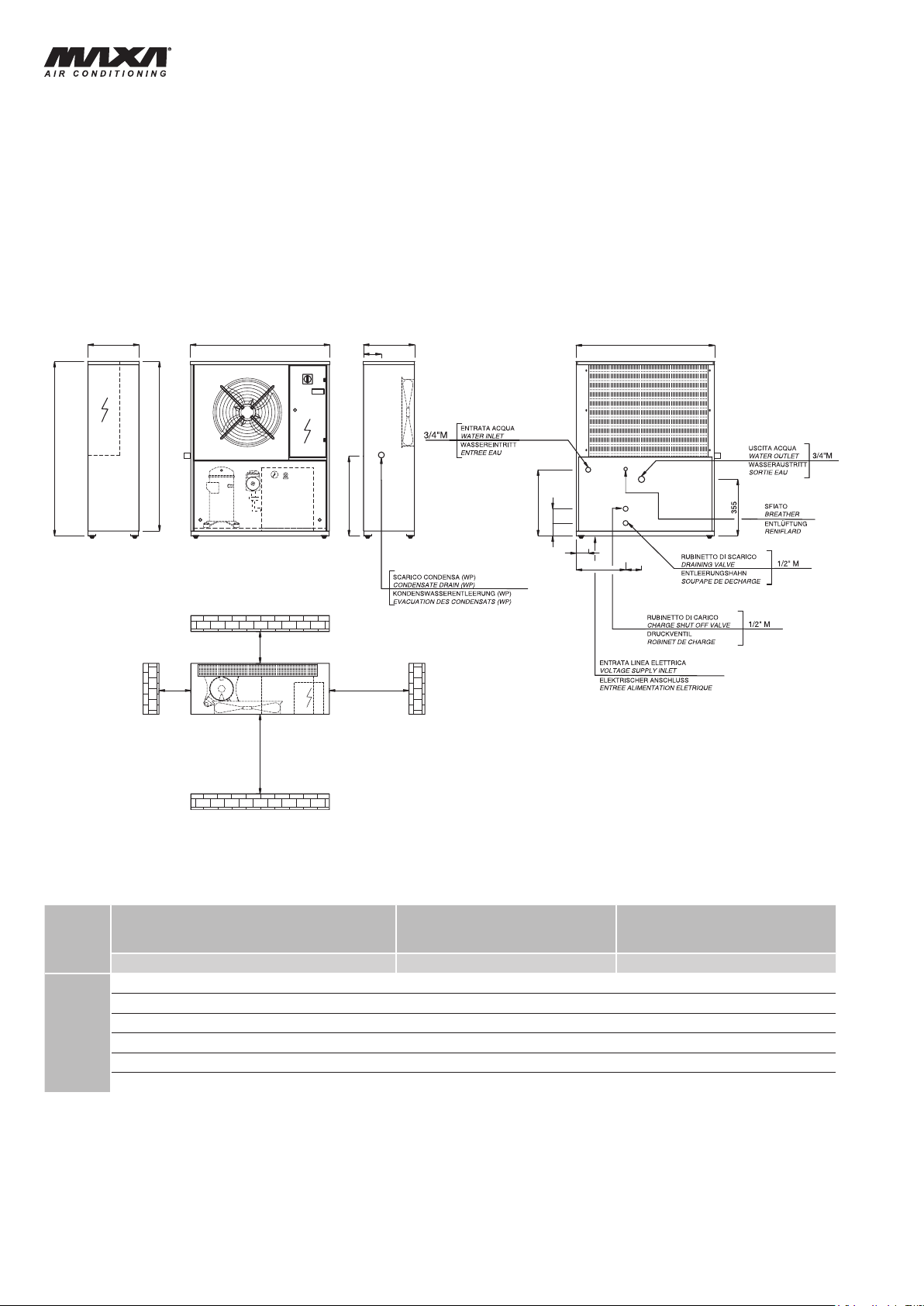
DIMENSIONI DI INGOMBRO, PESI, SPAZI DI
RISPETTO E COLLEGAMENTI IDRAULICI
AUSSENMAßE, GEWICHTE, RAUMBEDARF
UND HYDRAULISCHE ANSCHLÜßE
DIMENSIONS, WEIGHTS, CLEARANCES
AND HYDRAULIC CONNECTIONS
ENCOMBREMENTS, POIDS, ESPACES
POUR ENTRETIEN ET RACCORDEMENTS
HYDRAULIQUES
MOD.
Peso in funzione / Operating weight
Betriebsgewicht / Poids en fonction
(kg) Ø Ø
15
18
21
25
31
41
Per le unità a pompa di calore maggiorare il peso del 10%.
Für die Wärmepumpeausführungeinheiten muß das Gewicht
um 10% erhöht werden.
121
123 3/4" M 3/4" M
131 3/4" M 3/4" M
135 3/4" M 3/4" M
143 3/4" M 3/4" M
145 3/4" M 3/4" M
Entrata acqua / Water inlet
Wassereintritt / Entrée eau
3/4" M 3/4" M
For units in heat pump version increase the weight by 10%.
Pour les groupes à pompes à chaleur majorer le poids de 10%.
Uscita acqua / Water outlet
Wasseraustritt / Sortie eau
18
Page 19
HWAL-A 15÷81
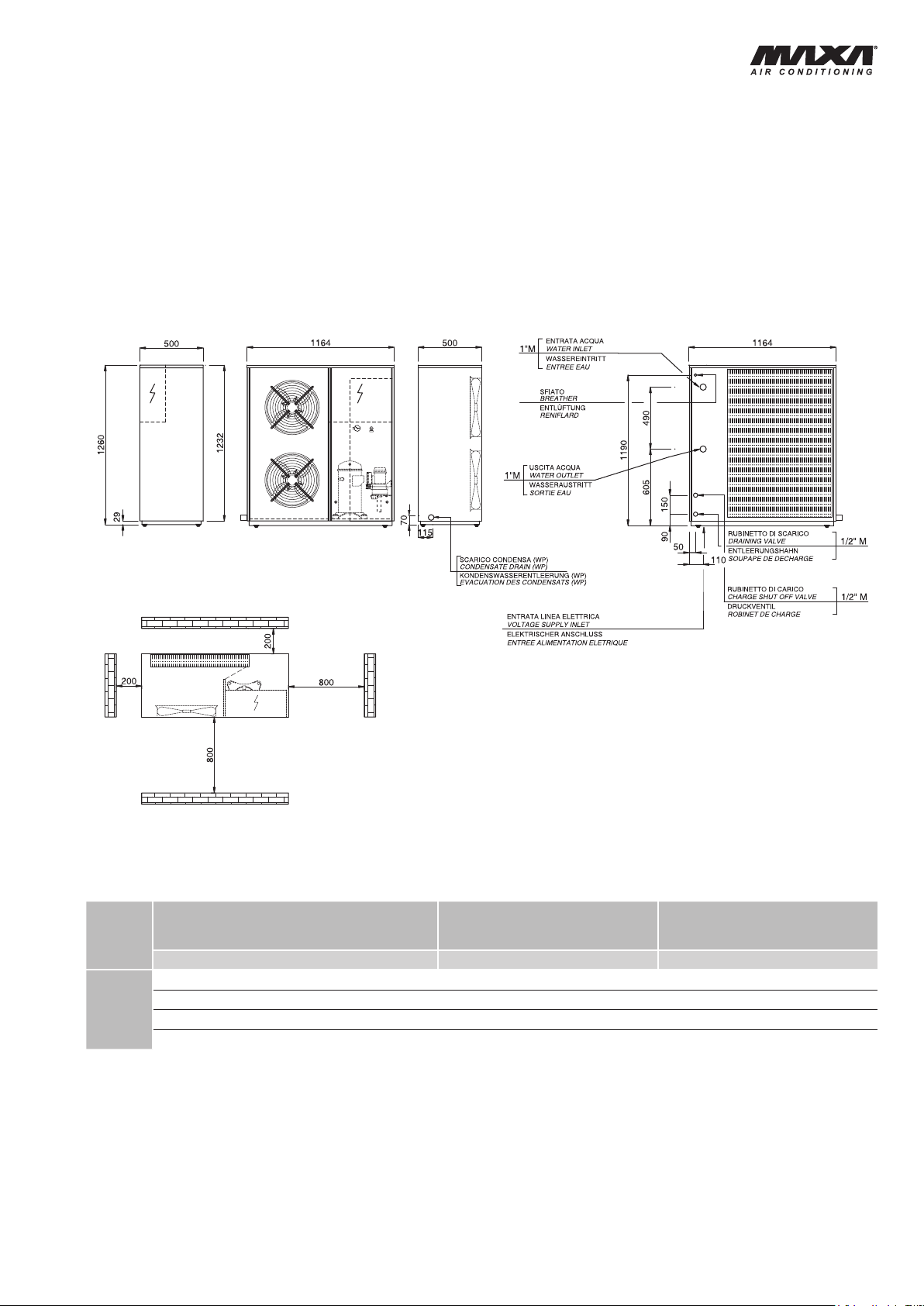
DIMENSIONI DI INGOMBRO, PESI, SPAZI DI
RISPETTO E COLLEGAMENTI IDRAULICI
AUSSENMAßE, GEWICHTE, RAUMBEDARF
UND HYDRAULISCHE ANSCHLÜßE
DIMENSIONS, WEIGHTS, CLEARANCES
AND HYDRAULIC CONNECTIONS
ENCOMBREMENTS, POIDS, ESPACES
POUR ENTRETIEN ET RACCORDEMENTS
HYDRAULIQUES
Peso in funzione / Operating weight
MOD.
51
61
71
81
Per le unità a pompa di calore maggiorare il peso del 10%.
Für die Wärmepumpeausführungeinheiten muß das Gewicht
um 10% erhöht werden.
Betriebsgewicht / Poids en fonction
(kg) Ø Ø
242
244
246
248
Entrata acqua / Water inlet
Wassereintritt / Entrée eau
1" M
1" M
1" M
1" M
For units in heat pump version increase the weight by 10%.
Pour les groupes à pompes à chaleur majorer le poids de 10%.
Uscita acqua / Water outlet
Wasseraustritt / Sortie eau
1" M
1" M
1" M
1" M
19
Page 20
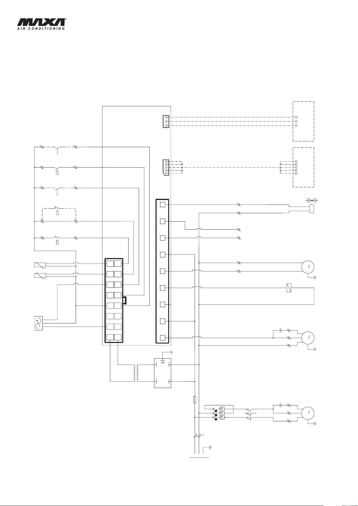
HWAL-A 15÷81
12V
230V
MULTI NETWORK
12~
12~
DO5
12=
5=
AO1 ID5
GND
ST 500
INTERFACE
KEYBOARD
REMOTE
ID4 ID3
AI4 AI3
ID2 ID1
AI2 AI1
TTL KEYB
2
4
3
1
N N N
D01
N
D02 Tk1 D04 D03
SR
MP
MV
TR
CMV
A2
KMC
A1
CE
ST2
ST1
E/I
SP.H
SP.L
SP.W
A3
FLC
YV.I
MC
QS
CMC
KMC
QMC
F1
1
3
2
4
5
6
3
4
12
56
34
12
1
MM
1
M
1
I >I >I >
X2:44
X2:N
X2:45
X2:17
X2:11
X2:00
X2:00
X2:15
X2:16
X2:12
X2:00
X2:00
X2:00
X2:34
X2:N
X2:90
X2:91
X2:S
X2:R
X2:C
X2:N
X2:36
230V/1/N/50HZ
PEN
L1
SCHEMA
ELETTRICO - MODELLI 15 ÷ 41
VERSIONI: HWAL-A - HWAL-A/WP
SCHALTPLAN
BAUVARIANTE:
- MODELLE 15 ÷ 41
HWAL-A - HWAL-A/WP
ELECTRICAL DIAGRAM - MODELS 15 ÷ 41
VERSION:
HWAL-A - HWAL-A/WP
DIAGRAMME ÉLECTRIQUE - MODEL 15 ÷ 41
VERSION: HWAL-A - HWAL-A/WP
- Legenda schema elettrico a pagina 22.
- Schaltplan Erklärung auf Seite 22.Schaltplan Erklärung auf Seite 22.
20
- Wiring diagram explanation on page 22.Wiring diagram explanation on page 22.
- Explication de le diagramme électrique à la page 22.Explication de le diagramme électrique à la page 22. 22.
Page 21
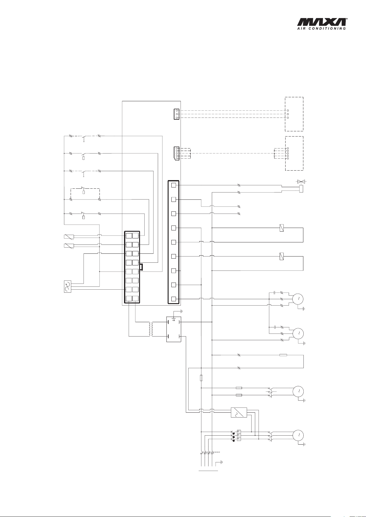
HWAL-A 15÷81
12V
230V
MULTI NETWORK
12~
12~
DO5
12=
5=
AO1 ID5
GND
ST 500
INTERFACE
KEYBOARD
REMOTE
ID4 ID3
AI4 AI3
ID2 ID1
AI2 AI1
TTL KEYB
2
4
3
1
L1
L3
L2
14
11
12
N N N
D01
N
D02 Tk1 D04 D03
SR
KMP
MP
MC
KMC
QS
QMC
FMP
MV1
MV2
F1
TR
CMV1
CMV2
A2
KMC
KMP
A1
CE
ST2
ST1
E/I
SP.H
SP.L
SP.W
A3
FLC
KF
RC
YV.I
4
231
6
5
4
2
357
468
3
1
1 2
6 5
M
3
1
M
M
M
1
1
I >I > I >
X2:1
X2:N
X2:44
X2:45
X2:N
X2:44
X2:N
X2:46
X2:17
X2:11
X2:00
X2:00
X2:15
X2:16
X2:12
X2:00
X2:00
X2:00
X2:34
X2:N
X2:90
X2:9
1
400V/3/N/50HZ
L1PEL2NL3
SCHEMA
ELETTRICO - MODELLI 51 ÷ 81
VERSIONI: HWAL-A - HWAL-A/WP
SCHALTPLAN
BAUVARIANTE:
- MODELLE 51 ÷ 81
HWAL-A - HWAL-A/WP
ELECTRICAL DIAGRAM - MODELS 51 ÷ 81
VERSION:
HWAL-A - HWAL-A/WP
DIAGRAMME ÉLECTRIQUE - MODEL 51 ÷ 81
VERSION:
HWAL-A - HWAL-A/WP
- Legenda schema elettrico a pagina 22.
- Schaltplan Erklärung auf Seite 22.Schaltplan Erklärung auf Seite 22.
- Wiring diagram explanation on page 22.Wiring diagram explanation on page 22.
- Explication de le diagramme électrique à la page 22.Explication de le diagramme électrique à la page 22. 22.
21
Page 22
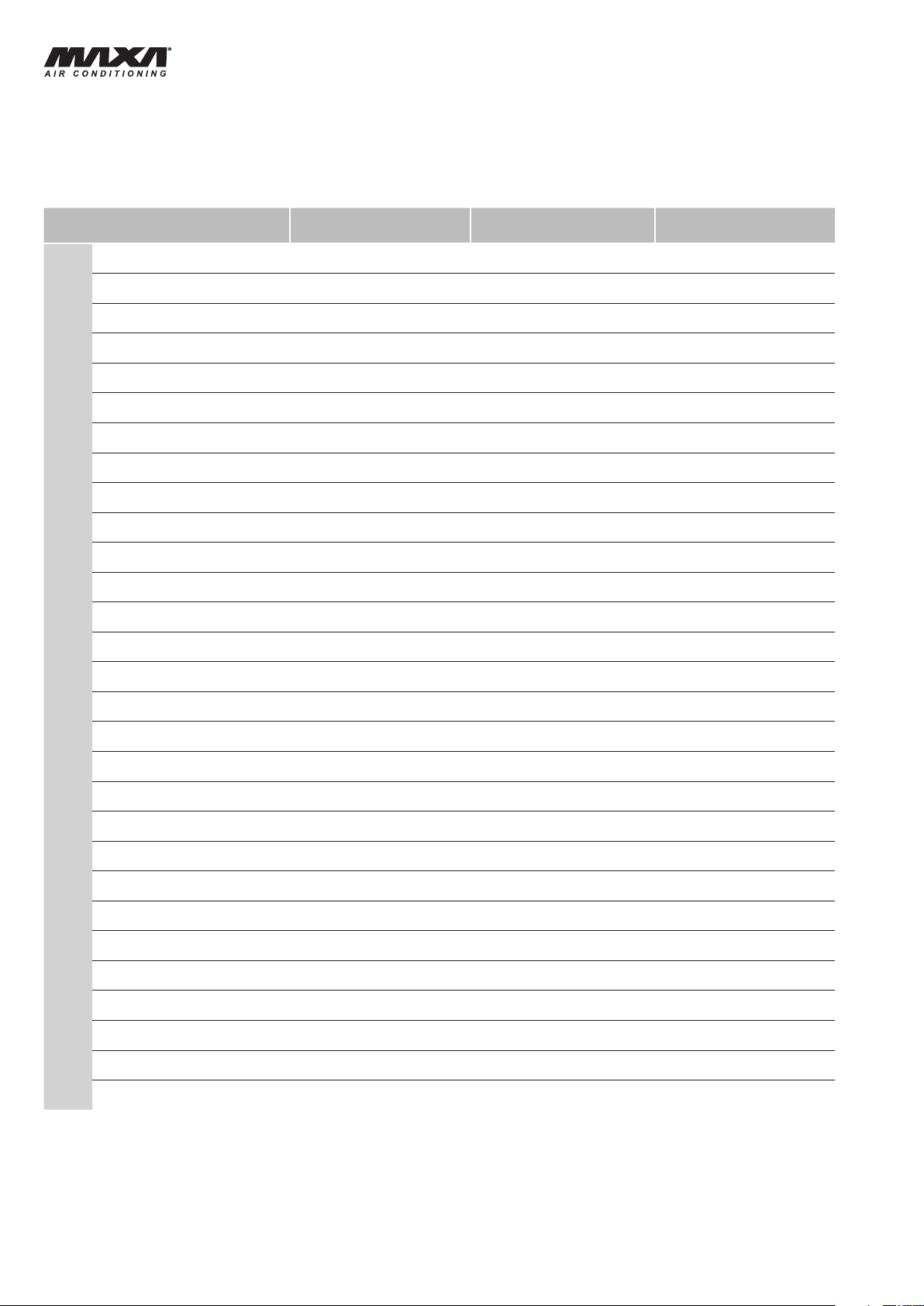
HWAL-A 15÷81
LEGENDA SCHEMI
ELETTRICI
SCHALTPLÄNE ERKLÄRUNG
DENOMINAZIONE DESIGNATION BEZEICHNUNG DESIGNATION
A1
A2
A3
CE
CMC
CMV1
CMV2
E/I
F1
FLC
FMP
Controllo elettronico Electronic control Elektronischer controller Commande életronique
Terminale remoto Remote terminal Fernbedienungstafel
Interfaccia seriale Serial interface Serielle schnittstelle Interface serie
Consenso esterno External interlock Externe zustimung Consentement ext.
Condensatore compressore Compressor condenser Kondensator Verdichter Condenseur compresseur
Condensatore ventilatore Fan condenser Kondensator gebläse Condenseur ventilateur
Condensatore ventilatore Fan condenser Kondensator gebläse Condenseur ventilateur
Commutatore
estate/inverno (WP)
Fusibile Fuse Sicherung Fusible
Filtro antidisturbo Filter for harmonic current Filter für harmonische Ströme
Fusibile pompa Pump fuse Sicherung pumpe Fusible du pompe
Summer/Winter
Changeover (WP)
ELECTRICAL DIAGRAMS EPLANATION
EXPLICATION DE LE DIAGRAMMES ÉLECTRIQUES
Tableau de controle
a distance
Umschalter
Sommer/Winter (WP)
Comm. Été/Hiver (WP)
Filtre pour courants harmoniques
KF
KMC
KMP
MC
MP
MV1
MV2
QMC
QS
RC
SPH
SPL
SPW
SR
ST1
ST2
Controllo sequenza fasi Control phase relay Phasenrelais Controle de phase
Teleruttore compressore Compressor contactor Verdichter Schutz
Teleruttore pompa Pump contactor Pumpen Schutz Telerupteur pompe
Compressore Compressor Verdichter Compresseur
Motore pompa Pump motor Pumpemotor Pompe
Motore ventilatore Fan motor Gebläse Ventilateurs
Motore ventilatore Fan motor Gebläse Ventilateurs
Salvamotore compressore Compressor overload
Sezionatore generale Main switch Hauptschalter Interrupteur general
Resistenza compressore
Pressostato alta pressione High pressure switch Hochdruckschalter
Pressostato bassa
pressione (accessorio)
Pressostato differenziale acqua
Sonda raziometrica 0-5 V. probe 0-5 V. Fühler 0-5 V. sonde
Sonda di lavoro Working probe Wassertemp.-fühler Sonde du travail
Sonda antigelo Antifreeze probe Frostschutzfühler Sonde antigel
Compressor crankcase
heater
Low pressure
switch (accessory)
Water different pressure
switch
Motorschutzschalter
verdichter
Kubelwannenheizung
Niederdruckschalter
(Zubehör)
Wasser-differenz
druckschalter
Telerupteur
compresseur
Sauf-motor compresseur
Resistence carter du
compresseur
Pressostat de haute
pression
Pressostat de basse
pression (accessoire)
Pressostat différentiel eau
TR
YVI
22
Trasformatore Control transformer Trafo Trasformateur
Valvola di inversione ciclo (WP) 4 way valve (WP) 4-wege-ventil (WP)
vanne d'inversion à
4 voies (WP)
Page 23

HWAL-A 15÷81
CONSIGLI PRATICI DI INSTALLAZIONE
Posizionamento:
- Osservare scrupolosamente gli spazi di rispetto indicati a catalogo.
- Verificare che non vi siano ostruzioni sull’aspirazione della batteria alettata
e sulla mandata dei ventilatori.
- Posizionare l’unità in modo da rendere minimo l’impatto ambientale (emissione
sonora, integrazione con le strutture presenti, ecc.).
Collegamenti elettrici:
-
Consultare sempre lo schema elettrico incluso nel quaderno tecnico, ove sono sempre
riportate tutte le istruzioni necessarie per effettuare i collegamenti elettrici.
- Dare tensione all’unità (chiudendo il sezionatore) almeno 12 ore prima
dell’avviamento per permettere l’alimentazione delle resistenze del carter,
ove presenti. Non togliere tensione alle resistenze del carter, ove presenti,
durante i brevi periodi di fermata dell’unità.
- Prima di aprire il sezionatore fermare l’unità agendo sugli appositi interruttori
di marcia, o in assenza sul comando a distanza.
- Prima di accedere alle parti interne dell’unità, togliere tensione aprendo il
sezionatore generale.
- E’ vivamente raccomandata l’installazione di un interruttore magnetotermico a
protezione della linea elettrica di alimentazione (a cura dell’installatore).
Collegamenti elettrici da effettuare:
- Cavo di potenza tripolare + neutro + terra; Consenso esterno; Riporto
allarme a distanza.
Collegamenti idraulici:
- Sfiatare accuratamente l’impianto idraulico, a pompa spenta, agendo sulla valvolina
di sfiato. Questa procedura è particolarmente importante in quanto anche piccole
bolle d’aria possono causare il congelamento dell’evaporatore.
- Scaricare l’impianto idrico durante le soste invernali o usare appropriate
miscele anticongelanti.
- Installare sempre un filtro a rete metallica sull'ingresso dell'unità a protezione
dello scambiatore a piastre.
- Realizzare il circuito idraulico includendo i componenti indicati negli schemi
raccomandati (valvole di sfiato, valvole di intercettazione, valvola di taratura,
giunti antivibranti, ecc.).
Avviamento e manutenzione:
- Attenersi scrupolosamente a quanto indicato nel manuale di uso e manutenzione.
Tali operazioni devono comunque essere effettuate da personale qualificato.
INSTALLATION RECOMMENDATIONS
Location:
- S t r i c tly al l o w c l earanc e s a s i n dica t e d i n t h e cata l o g u e .
- Ensure there are no obstructions on the air suction and discharge
side.
- Locate the unit in order to be compatible with environmental requirements
(sound level, integration into the site, etc.).
Electrical connections:
- Check the wiring diagram enclosed with the unit, in wich are always present
all the instructions necessary to the electrical connections.
- Supply the unit at least 12 hours before start-up, in order to turn crankcase
heaters, if available, on. Do not disconnect electrical supply during temporary
stop periods (i.e. week-ends).
- Before opening the main switch, stop the unit by acting on the suitable
running switches or, if lacking, on the remote control.
- Before servicing the inner components, disconnect electrical supply by
opening the main switch.
- The electrical supply line must be equipped with an automatic circuit breaker
(to be provided by the installer).
Electrical connections to be done:
- Three-wire power cable + neutral cable + ground cable; External interlock;
Remote alarm signalling.
Hydraulic connections:
- Carefully vent the system, with pump turned off, by acting on the vent valves.
this procedure is fundamental: little air bubbles can freeze the evaporator
causing the general failure of the system.
- Drain the system during seasonal stops (wintertime) or use proper mixtures
with low freezing point.
- Always install a metallic lter on the unit inlet in order to protect the plate
exchanger.
- Install the hydraulic circuit including all the components indicated in the
recommended hydraulic circuit diagrams (vent valves, balancing valve,
shut off valves exible connections, etc.).
Start up and maintenance operations:
- Strictly follow what reported in use and maintenance manual. All these
operations must be carried on by trained personnel only.
HINWEISE ZUR INSTALLATION
Aufstellung:
- Für ausreichende Be-und Entlüftung des Gerätes sorgen.
- Die Aufstellung des Gerätes ist so vorzunehmen das es allseitig erreichbar ist.
- Es ist darauf zu achten, daß es am Aufstellungsort integrierbar ist, das heißt
Beachtung der Schallentwicklung und die Integration in die vorhandenen
Strukturen.
Elektrische Anschlüsse:
- Beachten Sie die beigefügten Schaltpläne nach welchen der
Elektroanschluß vorzunehmen ist.
- Das Gerät ist mindestens 12 Stunden vor der Inbetriebnahme mit Spannung
zu versorgen, um die Kurbelwannenheizung des Verdichters, falls Verflügbar,
in Betrieb zu setzen. Die Stromversorgung der Kurbelwannenheizung,
falls Verflügbar, ist auch während der Stillstandszeit des Gerätes
sicherzustellen.
- Vor dem Öffnen der Sicherungen das Gerät ausschalten, durch Betätigung
des entsprechenden Hauptschalters, oder über die Fernbedienung.
- Vor dem Öffnen des Gerätes ist die Spannungsversorgung zu unterbrechen.
- Die Installation der Hauptsicherungen ist durch den Elektroinstallateur
vorzunehmen.
Auszuführende elektrische Anschlüsse:
- Anschlußkabel 5 Adern, 3 Phasen, Neutral, Schutzleiter; Externe
Bedieneinrichtung; Alarmfernmeldung.
Hydraulische Anschlüsse:
- Sorgfältig das hydraulische System bei abgeschalteten Pumpen entlüften.
Dieser Vorgang ist besonders wichtig, da auch kleine Luftblasen eine
Vereisung des Verdampfers bewirken können.
- Das hydraulische System ist während der Winterpause zu entleeren, oder
entsprechende Frostschutzmischung anzuwenden.
- Zum Schutz des Platten-Wärmetauschers ein Metallfilter bei Einheitseintritt
immer einbauen.
- Den hydraulischen Kreislauf unter Einbezeichung der in den empfohlenen
Diagrammen angegebenen Bestandteile (Entlüftungsventile, Absperrventile,
Ausgleichsventil, schwingungsdämpfende Kupplungen) schließen.
Inbetriebnahme und Wartung:
- Bitte strikt die Betriebs- und Wartungsanleitung befolgen. Alle darin
beschriebenen Arbeiten dürfen nur von Fachleuten ausgeführt werden.
CONSEILS PRATIQUES POUR L’INSTALLATION
Mise en place:
- Observer scrupuleusement les espaces pour l’entretien tels qu’indiqués
précédemment.
- Vérier qu’il n’existe aucune obstruction sur l’aspiration de l’air au travers
de la batterie ailettée et sur le refoulement des ventilateurs.
- Positionner l’unité de manière à n’affecter qu’au minimum l’environnement
(émission sonore, intégration sur le site, etc.).
Raccordements électriques:
- Consulter toujours le schéma électrique joint à la machine où sont
toujours reportées toutes les instructions nécessaires pour effectuer les
raccordements électriques.
-
Mettre la machine sous tension (en fermant le sectionneur) au moins 12 h avant
le démarrage pour permettre l’alimentation des résistances du carter ou il y à.
Ne pas supprimer l’alimentation aux résistances du carter, ou il y à, durant les
cours arrêts de la machine.
- Avant d’ouvrir le sectionneur arrêter l’unité en agissant sur les interrupteurs
prévus à cet effet ou bien sur la commande à distance.
- Avant d’accéder aux parties internes de l’unité, couper l’alimentation
électrique en ouvrant le sectionneur général.
- Il est vivement recommandé d’installer un disjoncteur magnéto-thermique en
protection de la ligne d’alimentation électrique (à la charge de l’installateur).
Raccordements électriques à effectuer:
- Câble de puissance tripolaire + neutre + terre; Contacts extérieurs; Report
à distance des alarmes.
Raccordements hydrauliques:
- Purger avec soin l’installation hydraulique, pompe hors service, en intervenant
sur les purgeurs. Cette procédure est particulièrement importante, car la
présence même de petites bulles d’air peut causer le gel de l’évaporateur.
- Vidanger l’installation hydraulique pendant l’hiver ou utiliser un mélange
antigel approprié.
- Installer toujours un ltre metallique à l'entrée du group au n de proteger
l'echangeur à plaques.
- Réaliser le circuit hydraulique en incluant tous les composants indiqués
dans les schémas relatifs (purgeurs, vannes d’arrêt, robinet d'équilibrage,
jonctions antivibratiles, etc.).
Mise en service et entretien:
-
Se tenir scrupuleusement à ce qui est indiqué dans le manuel d’utilisation et
d’entretien. Ces opérations seront toutefois effectuées par du personnel qualié.
23
Page 24

Via Gettuglio Mansoldo (Loc. La Macia)
A I R C O N D I T I O N I N G
37040 Arcole
Verona - Italy
Tel. +39 - 045.76.36.585 r.a.
Fax +39 - 045.76.36.551 r.a.
www.maxa.it
e-mail: [email protected]
I dati riportati nella presente documentazione sono solamente
indicativi. Il costruttore si riserva la facoltà di apportare in qualsiasi
momento tutte le modifiche ritenute necessarie.
Technische Änderungen die der Verbesserung und Optimierung
dienen, vorbehalten. Der Hersteller behält das Recht auf diese
Änderungen ohne Ankündigung vor.
The data indicated in this manual is purely indicative. The manufacturer reserves the right to modify the data whenever it is
considered necessary.
Les données reportées dans la présente documentation ne sont
qu' ndicatives. Le constructeur se réserve la faculté d'apporter à
tout moment toutes les modications qu'il jugera nécessaires.
 Loading...