

Page 1
TECHNICAL MANUAL 2013
SPLIT LIGHT MULTI DC INVERTER
MODELS
Indoor units Outdoor units
BDLM26A2 BD2M53A3
BDLM36A2 BD3M98A3
BDLM53A2
This manual has been created for informative purpose. The company declines every responsibility for the results of projecting or installation based on the explanations and the technical specifications
given in this manual. Is besides forbidden the reproduction under any form of the texts and of the figures contained in this manual.
Page 2

Serie / Series / Serie / Serie
TECHNICAL MANUAL
SPLIT LIGHT MULTI DC
Emissione / Issue
Ausgabe / Emission
03 - 2013
Catalogo / Catalogue / Katalog / Catalogue
Sostituise / Supersade
Ersetzt / Remplace
04 - 2011
MTE01028D2820-01
3
Page 3

INDICE
1. Specifics.....................................................................................................................................5
1.1 Indoor units specific.................................................................................................................. 5
1.2 Outdoor units specifics ............................................................................................................. 6
1.3 Noise criteria curve tables for both models ..............................................................................7
2. Outlines and dimensions ............................................................................................................ 7
2.1 Indoor unit ................................................................................................................................7
2.2 Outdoor unit .............................................................................................................................8
3. Refrigerant circuit ....................................................................................................................... 9
4. Electrical diagram.....................................................................................................................10
4.1 Indoor units ............................................................................................................................10
4.2 Outdoor unit ...........................................................................................................................11
5. Printed circuit ...........................................................................................................................12
5.1 Indoor units ............................................................................................................................12
5.2 Indoor units ............................................................................................................................13
6. Control functions ...................................................................................................................... 14
6.1. Temperature Parameters ...................................................................................................... 14
6.2. Basic functions ...................................................................................................................... 14
6.3. Others ................................................................................................................................... 14
6.4. Displayer ...............................................................................................................................15
7. Outdoor units Operation ........................................................................................................... 17
7.1. Temperature parameters....................................................................................................... 17
7.2. System basic function ........................................................................................................... 17
8. Troubleshooting .......................................................................................................................20
8.1. Malfunction Display of Indoor Unit.........................................................................................20
8.2. How to Check simply the main part....................................................................................... 21
8.3 Malfunction Display of Outdoor Units ..................................................................................... 26
8.4 Malfunction checking and elimination..................................................................................... 27
Appendix.....................................................................................................................................36
Appendix 1: Resistance Table of Ambient Temperature Sensor for Indoor and Outdoor Units(15K).......................... 36
Appendix 2: Resistance Table of Outdoor and Indoor Tube Temperature Sensors(20K) ........................................... 37
Appendix 3: Resistance Table of Outdoor Discharge Temperature Sensor(50K)........................................................ 38
4
Page 4

1. Specifics
1.1. Outdoor units specifics
Models
Power supply
Capacity
Power input kW 1,5(0,5~2,5) 2,15(0,6~4,5)
Cooling
Absorbed current A 6,8 10,9
S.E.E.R. W/W 5,60-A+ 5,10-A
Capacity
Power input kW 1,5(0,5~2,7) 2,28(0,8~3,9)
Heating
Absorbed current A 6,8 11,4
S.C.O.P. W/W 3,80-A 3,80-A
Compressor trademark
Compressor model QXA-B141zF030A QXAS-D23zX090B
Compressor type
Compressor oil
Comp. oil charge L
L.R.A.
Compressor RLA A 7,2
Compressor input
Compressor capacity
Comp. Overload protector 1NT11L-6233
Throttling method
Starting method
Working temp range °C
Condenser material Aluminum fin-copper tube
Rows-Fin Gap
Coil length (l) x height (H) x coil width (L) mm 851 x 660 x 38,1
Fan motor apeed rpm 880/700/500
Output of fan motor W
Fan Motor RLA A 0,56
Outdoor unit
Fan motor capacitor μF 4
Outdoor air flow volume m3/h 2600/2300/1600
Fan type-piece
Fan diameter mm
Defrosting method
Climate type
Isolation
Moisture protection
Permissible excessive operating pressure for the discharge side Mpa
Permissible excessive operating pressure for the suction side
Sound pressure level
Sound power level
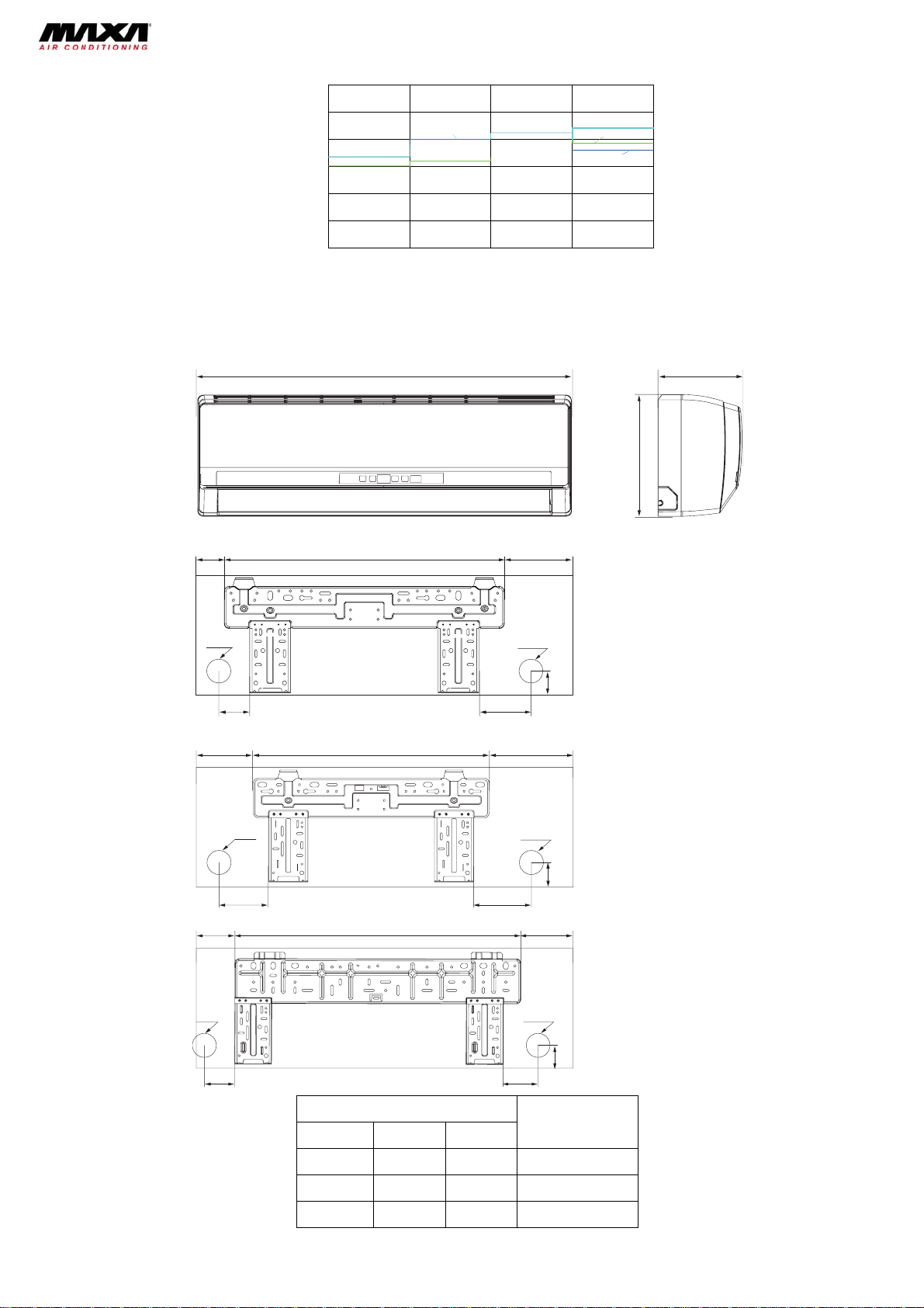
Outline dimension mm 963 x 700 x 396 1001 x 790 x 427
Packing dimension mm 1029 x 458 x 750 1083 x 488 x 855
Net / Gross weight kg 50/55 96/74
Refrigerant charge kg R410A / 1,40
Max. connection pipe length (for each indoor unit)
Difference in livel m 10 10
Gas additional charge g/m
pipe
Pipe out.
Connection
diameter
Operating temperature °C
Liquid
Gas Inch 3/8 1/2
V- Ph, Hz 230V 220 ~ 240V , 50Hz
kW 5,0(2,0~6,3) 7,0(2,0~10,0)
Btu/h 17,0(6,9~21,5) 24,2(6,8~34,1)
kW 5,6(2,5~6,6) 8,5(3,2~11,0)
Btu/h 19,1(8,5~22,6) 29,0(10,9~37,5)
ZHUHAI LANDA COMPRESSOR CO. LTD
W 1440
4320
Electronic expansion valve
mm 2-1.4
MPa 2,5
dB(A) 56/53/50 58/54/52
dB(A) 66/63/60 68/64/62
m ≤20 ≤20
Inch 1/4 1/4
BD2M53A3 BD3M98A3
DC inverter Rotary
RB68EP
0,39 0,95
11,5
2550
7250
Transducer starting
-15°C ≤ T ≤ 48°C
982,2 x 748 x 38,1
690/600/500
60
0,6
3,5
3300/2900/2400
Axial fan –1
520 552
Automatic defrost
T1
I
IP24
4,3
R410A / 2,2
1/4
3/8
-15 ~ 48
5
Page 5

0
[
]
1.2 Indoor units specifics
MODELS BDLM26A2 BDLM36A2 BDLM53A2
Power supply
Total capacity
Power input W 10 10
Cooling
Absorbed current A 0,04 0,04
Total capacity
Power input W 10 10
Heating
Absorbed current A 0,04 0,04
Air flow volume
Dehumidifying volume l/h 0,6
Fan motor speed (SH/M/L) (r/min) 1320/1200/1100/950 1280/1080/1000/920
Fan Motor Capacitor μF 1 1
Fan motor full load Amp (FLA) A 0,144 0,22
Output of fan motor W 10 20
Motor model FN10A-PG FN20J-PG
Fan type-piece
Diameter-Length mm Ø85 X 596 Ø92 X 645
Evaporator
Pipe diameter
Row-Fin gap mm 2-1,5 2-1,4
Indoor Coil
Coil length (l)xheight (H)xcoil width (L)
Swing motor model MP24AA
Output of swing motor W 1,5 1,5
Fuse
Indoor sound level (H/M/L) dB(A) 39/34/28 40/35/30
Dimension (W/D/H) mm 790X174X265 845X180X275
Dimension of package (W/D/H) mm 870x248X355 918x258X370
Net weight/Gross weight
Liquid pipe
Gas pipe (to indoor unit)
(SH/H/M/L)**
(m3/h)
V-Ph, Hz
kW 2.600 3.500
Btu/h 8,8 11,9
kW 2.800 3.800
Btu/h 9,5 12,9
500 630
Cross flow fan – 1
Aluminum fin-copper tube
mm Ø7
mm 581X267X25,4 690X267X25,4
A PCB 3,15A
kg 9/11 10/12,5
mm Ø6 Ø6
mm Ø9,52 Ø9,52
The data of specifications are subject to change without prior notice. Please refer to the actual data specified on the
nameplate of the unit.
220 ~ 240V ○,1, 50Hz
230V
1,4
5.300
18,0
55
0,3
5.800
19,7
55
0,3
850
1,8
1420/1250/1150/105
1,5
0,31
20
FN20V-PG
Ø98 X 710
2-1,4
715×304,8x25,4
MP28VB
2,0
43/40/35
940/200/298
1013X288X395
13/16
Ø6
Ø12,7
Note: Test conditions:
Standard condition
Dry bulb temp. °C Wet bulb temp. °C Dry bulb temp. °C Wet bulb temp. °C
Indoor side state Outdoor side state
Rated cooling 27 19 35 24
Max. cooling 32 23 48 26
Min. cooling 21 15 18 -
Rated heating 20 15 7 6
Max heating 27 - 24 18
Min. heating 20 15 -15 -16
3) Microphone at a distance of 1m from the unit.
Approximate calculation from Sound Pressure Level to Sound Power Level:
*1.0*1.0
LL
21
- Average Sound Pressure Level
L
: Sound pressure level of front test point.
1P
L
: Sound pressure level of side test point for indoor unit
2P
- Approximate Sound Power Lever
L =10*lg
p
LL =
+10.
pW
+
PP
LL .
21,PP
.
1010(*2/1
6
Page 6
1.3 Noise criteria curve tables for both models
60
50
40
30
Noice/dB(A)
20
10
0
Low Middle High Super High
Indoor Fan Motor Rotating Speed
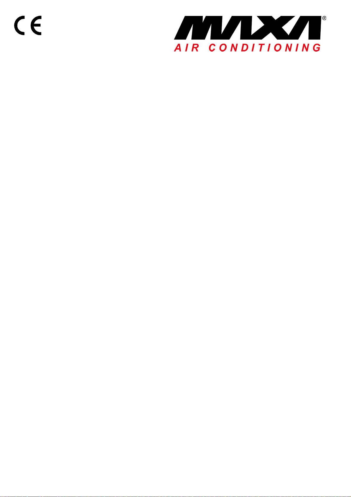
2. Outlines and dimensions
2.1 Indoor units
W
BDLM53A2
BDLM36A2
BDLM26A2
D
H
36
Φ55
Φ55
69
85
941506
BDLM26A2
09K Units
Φ55
40
8704
172542131
BDLM3A2
12K Units
Φ55
50
19469452
BDLM53A2
18K Units
Φ55
Φ55
61183
45
Dimension (mm)
Models
W H D
790 265 174 BDLM26A2
845 275 180 BDLM36A2
940 298 200 BDLM53A2
7
Page 7
8
92341
2.2 Outdoor units
a) BD2M53A3
560
700
396963
368
Unit:mm
b) BD3M98A3
924 370
1001
610
427
399
Unit:mm
790
8
Page 8
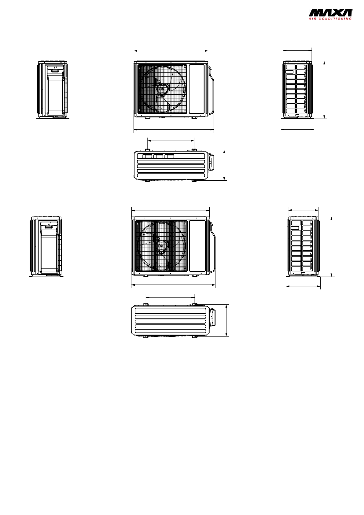
3. Refrigerant circuit
indoor
A heat exchanger
B heat exchanger
C heat exchanger
A3
B3
C3
filter
filter
filter
outdoor
filter
A
1
A2
B
1
B2
C
1
C2
outdoor heat exchanger
fan
4-way valve
SP
high pressure switch
Note: N ot available for 14K/1 8K
model
discharge silencer
discharge temperature
sensor
inverter comp resso r
gas -liquid separator
Note: N ot available for 1 4K/18K m od el
A1:A-unit electronic expansion valve A2:A-unit gas pipe temperature sensor A3:A-unit liquid pipe temperature sensor
B1:B-unit electronic expansion valve B2:B-unit gas pipe temperature sensor B3:B-unit liquid pipe temperature sensor
C1:C-unit electronic expansion valve C2:C-unit gas pipe temperature sensor C3:C-unit liquid pipe temperature sensor
D1:D-unit electronic expansion valve D2:D-unit gas pipe temperature sensor D3:D-unit liquid pipe temperature sensor
9
Page 9
4. Electrical diagram
4.1 Indoor units
BDLM26A2, BDLM36A2
TUBE
TEM.SENSOR
0
RT2
TUBE
CAP
JUMP
DISP1
RECEIVERAND
DISPLAY BOARD
DISP2
AP1
ROOM
TEM.SENSOR
0
RT1
ROOM
AP2
SWING-UD
M2
SWING
MOTOR
HEALTH-N
BU
COO L PLASMA
GENER ATOR
FAN
MOTOR
M1
PG
COM-OUT
HEALTH-L
PGF
AC-L
RD
N
1BU
3BK
2BN
4YEGN
EVAPORATOR
XT
N(1)
2
3
PE
OUTDOOR UNIT
BU
BK
BN
YEGN
BDLM53A2
NOTE:The parts with broken line is applicable
to the models with COOL PLASMA GENERATOR
TUBE
TEMP.SENSOR
0
RT2
TUBE
ROOM
TEMP.SENSOR
0
RT1
ROOM
CAP
AP2
JUMP
DISP1
DISP2
SWING-UD
FAN MOTOR
M1
PG
PGF
N
COM-OUT
AC-L
HEALTH-NHEALTH-L
1BU
3BK
2BN
XT
N(1)
2
3
4YEGN
PE
EVAPORATOR
BU
BK
BN
YEGN
OUTDOOR UNIT
M2
AP1
RECEIVER AND
DISPLAY BOARD
SWING
MOTOR
RD
COO L PLASMA
GENER ATOR
(optional)
BU
10
Page 10
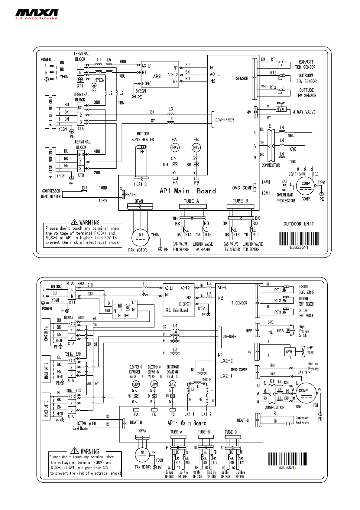
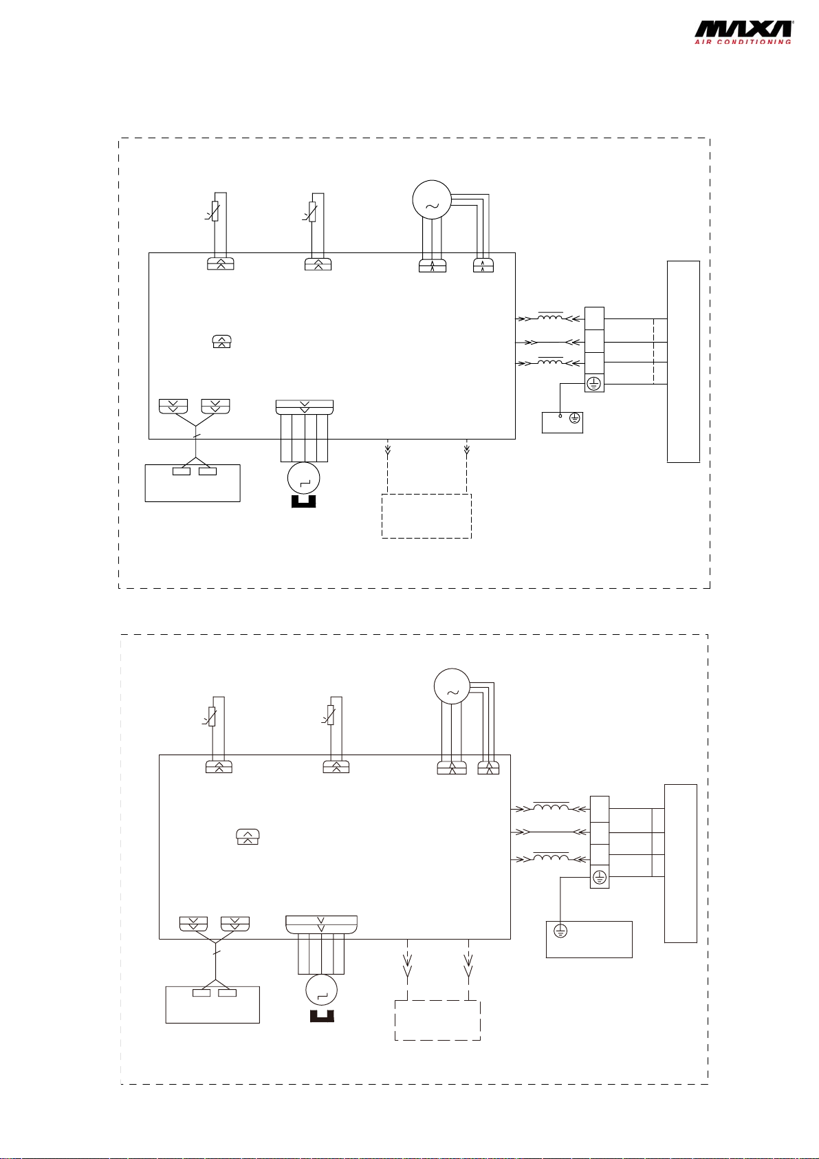
4.2 Outdoor unit
BD2M53A3
BD3M98A3
11
Page 11
r
r
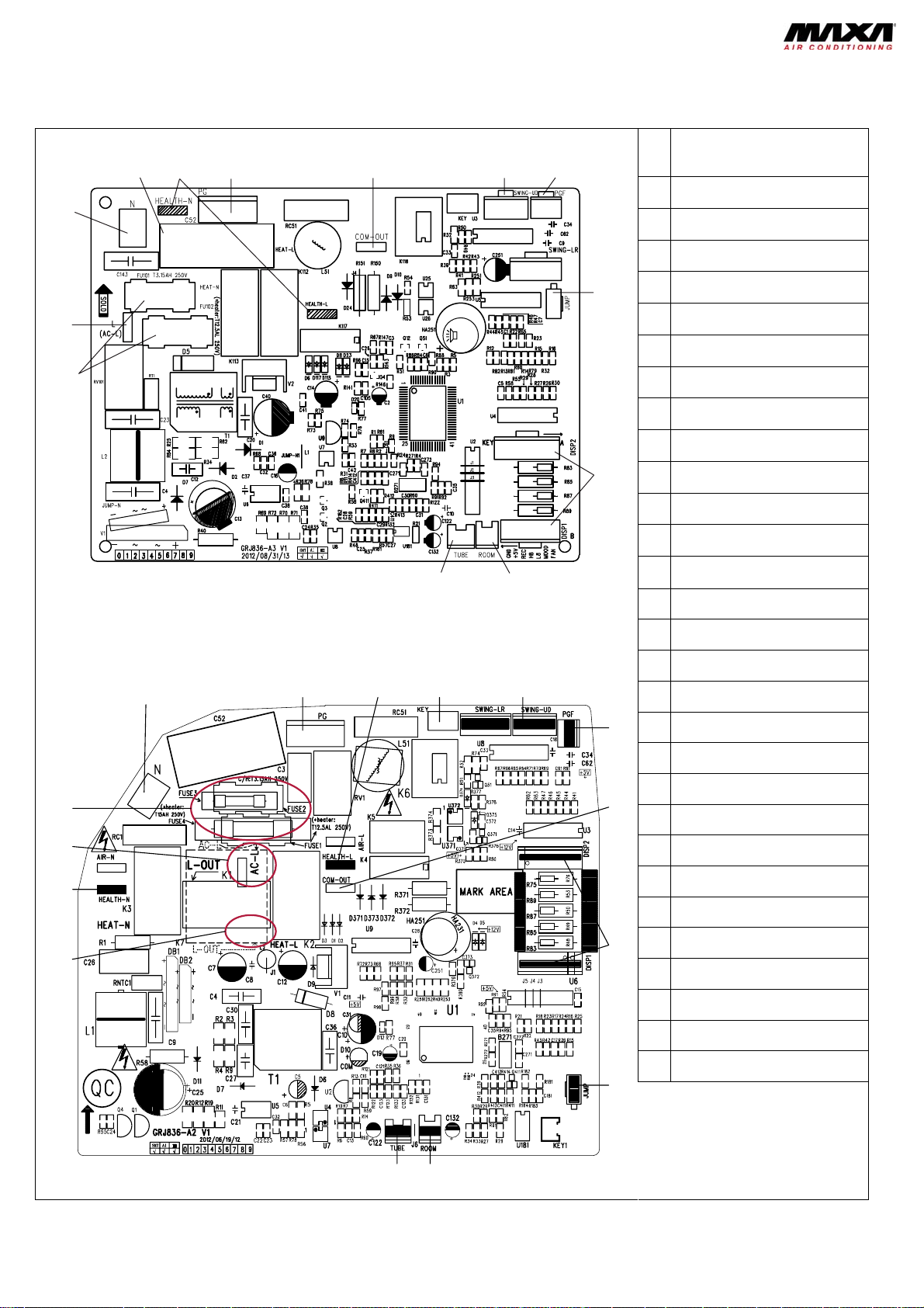
5. Printed circuits
5.1 Indoor units
Models: BDLM26A2, BDLM36A2
Top View
2
1
13
Model: BDLM53A2
Top View
1
853764
1112
234 5
9
10
No Part name
Power supply live wire connector
1
Power supply neutral wire
2
connector
Fan capacitor
3
Health function terminal
4
(optional)
5 Indoor fan wire terminal
Indoor and outdoor unit
6
communication wire terminal
Up & down swing control
7
terminal
Indoor fan feedback terminal
8
Jumper cap
9
Display panel terminal
10
Indoor ambient temperature
11
sensor
Indoor pipe temperature sensor
12
Protective tube
13
No Part name
1 Interface of neutral wire
2 Interface of PG motor
Interface of health function live
3
wire
6
4 Interface of auto button
5 Interface of up and down swing
6 Interface of PG feedback
15
14
13
12
1011
7
8
9
Interface of indoor and outdoor
7
unit communication
Interface of display
8
9 Interface of jumper cap
Interface of ambient temperature
10
senso
Interface of tube temperature
11
senso
Power supply interface of outdoor
12
live wire
Interface of heath function neutral
13
wire
14 Interface of live wire
15 Interface of fuse
12
Page 12
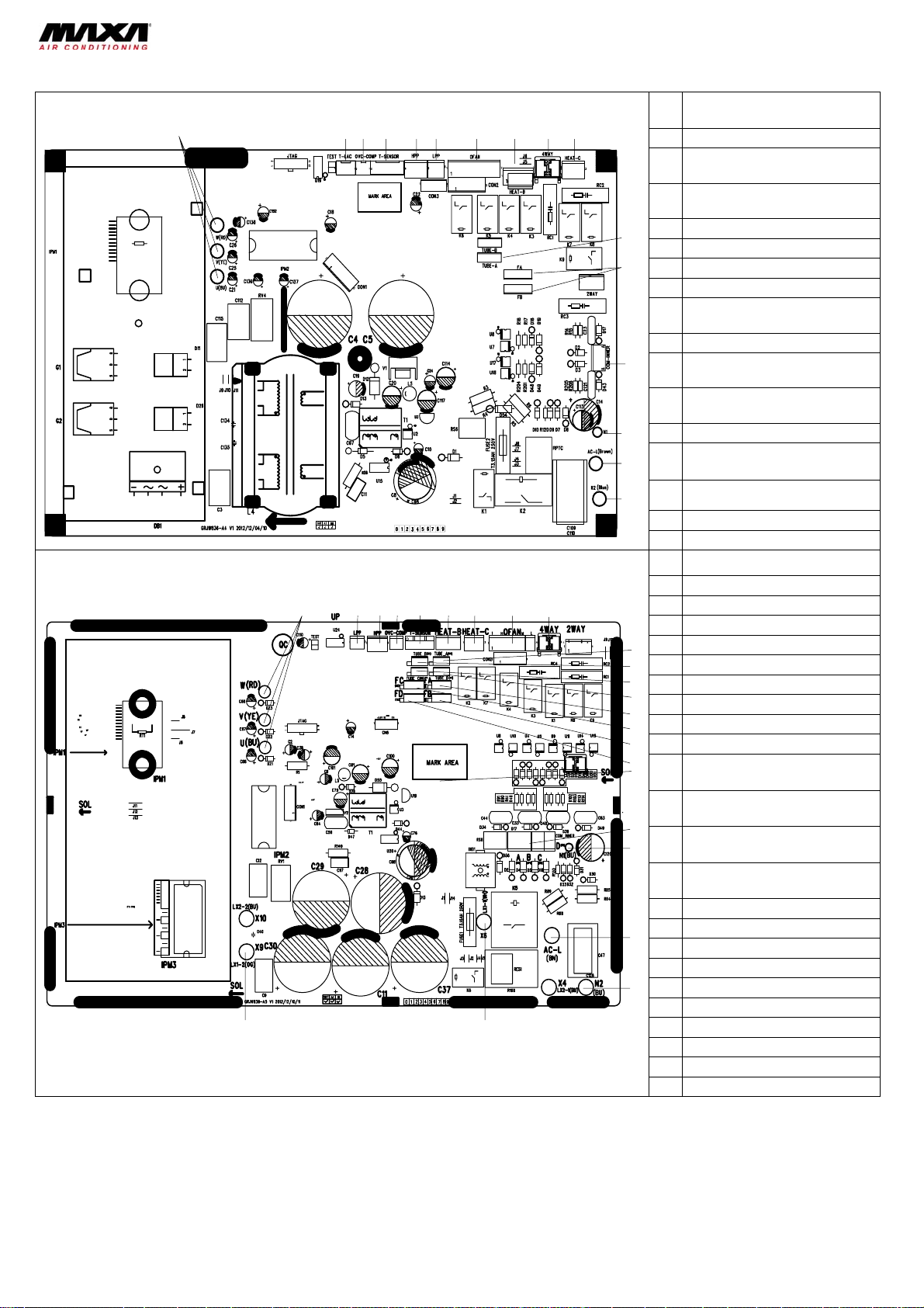
5.2 Outdoor units
3
516
71819
Model: BD2M53A3
1
Models: BD3M98A3
23
23 4 56 7 8 9 10
1
123456 879
22
No Part name
Compressor terminal
1
Temp. sensor terminal of low
2
ambient temp. cooling
Compressor overload protection
3
terminal
4 Outdoor temp. sensor terminal
11
5 High pressure protection terminal
12
13
14
15
16
10
11
12
1
14
1
1
20
21
Low pressure protection terminal
6
Outdoor fan terminal
7
Terminal of chassis electric
8
heating belt
4-way valve terminal
9
Terminal of compressor electric
10
heating belt
Temp sensor terminal of gas
11
valve and liquid valve
Electric expansion valve terminal
12
Terminal of IDU and ODU
13
communication wire
Terminal of communication
14
neutral wire
Live wire terminal
15
Neutral wire terminal
16
No Part name
1 Compressor terminal
High pressure protection
2
3 Low pressure protection
Compressor overload protection
4
5 Outdoor temp. sensor terminal
6 Terminal chassis electric heater
7 Terminal of comp. electric heater
Outdoor fan terminal
8
9 4-way valve terminal
Unit A liquid valve and gas valve
10
temp. sensor
Unit B liquid valve and gas valve
11
temp. sensor
Unit C liquid valve and gas valve
12
temp. sensor
Unit D liquid valve and gas valve
13
temp. sensor
14 Unit A electronic expansion valve
15 Unit B electronic expansion valve
16 Unit C electronic expansion valve
17 Unit D electronic expansion valve
Communication wire with indoor
18
19 Communication neutral wire
20 Live wire
21 Neutral wire
22 Reactor 1
23 Reactor 2
13
Page 13

6. Control functions
6.1. Temperature Parameters
• Indoor ambient temperature (Tin_amb.)
• Evaporator tube temperature (T
Setting temperature (T
set)
Note: The following function manual, the temperature unit is centigrade, if there is Fahrenheit, there will be
T(°F)=T(°Cx1.8+32.
6.2. Basic functions
6.2.1 Cooling mode
1. Temperature can be set in the range of 16 ~ 30°C.
2. The unit will firstly run at high fan speed for 8s and then switch to preset fan speed.
3. When error of outdoor unit occurs or the unit stops for protection, indoor unit will keep its original operating state.
6.2.2 Dehumidifying mode
1. Temperature can be set in the range of 16 ~ 30°C.
2. The unit will firstly run at high fan speed for 8s and then switch to low fan speed.
3. When error of outdoor unit occurs or the unit stops for protection, indoor unit will keep its original operating state.
6.2.3 Fan mode
1. The unit will firstly run at high fan speed for 8s and then switch to preset fan speed.
2. When error of outdoor unit occurs or the unit stops for protection, indoor unit will keep its original operating state.
6.2.4 Heating mode
1. Temperature can be set in the range of 16 ~ 30°C.
2. If compress stops at required temperature point, indoor fan will run by blowing residual heat.
3. If compress under heating mode stops for error, indoor fan will run by blowing residual heat.
4. Function of blowing residual heat:
Indoor fan switching into low speed will stops after 1 min delay.
5. Anti-cold air
After heating compressor runs, indoor fan runs according to the following conditions:
If compressor runs within 90s and T
above, indoor fan will run at low speed. After 3 min at low speed or T
running, indoor fan won't stop. Once at preset fan speed, it won't forcibly return to low speed.
6.2.5 AUTO mode
1) When T
2) When T
3) When 18°C < T
in_amb. ≥ 25°C, the unit runs under cooling mode, Tset = 25°C.
in_amb. ≤ 18°C, the unit runs under heating mode, Tset = 18°C. And it runs under fan.
in_amb. < 25°C, the unit keeps its original operating state. If first energization, it runs under fan mode.
6.3. Others
6.3.1 Buzzer
The air conditioner will send out Hua alert
6.3.2 Auto Button
When turn off the unit, press this button, the whole unit will run at auto mode, indoor fan motor will run in auto fan speed,
turn on the swing. At unit turns on, press the Auto button that the unit will turns off.
6.3.3 Auto fan speed control
Under Cool, Heat, Fan modes, indoor fan will accord to the ambient temperature select High, Mid, Low three speeds, the
dehumidifying mode auto fan speed is low. The switch of each fan mode should be 3.5mins.
6.3.4 Timer function
The common setting for Timer:
a) Timer on: At unit off, can set up the Timer On function, when Timer On act, the controller will run at original setting
mode, the Timer interval is 0.5hr, setting range is 0.5-24hrs.
in_tube)
in_tube < 35°C, indoor fan won't run. When Tin_tube ≥ 35°C or compressor run for 90s
in_tube ≥ 40°C, indoor fan runs at preset speed. Once
when it is energized or receives a control command.
14
Page 14

b) Timer off: At unit on, can set up the Timer Off function, when Timer Off act, the unit will turn off, the Timer interval is
0.5hr, setting range is 0.5-24hrs.
Hours setting for Timer:
a) Timer on: If unit is running then to set up the Timer On, the unit will go on running, if the unit is off to set up the Timer
On, when Timer On acts, the unit will run at the presetting modes.
b) Timer off: If unit is off then to set up the Timer Off, when setting the Timer off, the unit stand by, if unit is turned on to
set up Timer Off, when the Timer Off act, the system will stop to work.
c) Timer change: When unit is running in Timer mode, by operate the On/Off of remote controller to turn on or turn off the
unit, can reset up the Timer function, the unit will run at the mode of last setting.
If unit is running, at the same time to set up Timer On and Timer Off, the system will keep the present setting status, after
the Timer On. When system is running, at the same time to set up Timer On and Timer Off, the unit will keep the current
presetting working status, if Timer Off act, the unit will stop working.
When unit is stop running, at the same time to set up the Timer On and Timer Off, the unit will keep stop running, until
Timer On act, the unit will start to work, after this when Timer On of every day act, it will run at presetting modes, when
Timer Off act, the unit will stop to work.
If the setting for the Timer Off and Timer On are the same, the Timer Off will act.
6.3.5 Memory function
Contents of memory: Modes, Up and Down Swing, Light, Setting Temp. Setting fan speed, Common setting for Timer
(Hours will not memorized). After Timer Off, when re-power on, the unit will automatically turn on and run at memorized
contents.
There is no Timer Setting in the remote control order that the unit will memorize the remote control order of last setting
and it will run at that mode.
6.3.5 I Feel function
When controller received the orders that the controller will work according to ambient temperature which is sent by remote
control (Except Defrost and Anti-cool wind, it will still adopt the air conditioner self ambient sensor sampling value), the
remote control in every 10mins, to send the ambient temperature value to controller. 11mins later, the controller haven’t
received the ambient temperature value from the remote control that the air conditioner will run itself ambient temperature.
If there is no setting function that the ambient temperature will adopt the AC sensor sampling value. Power off will not
memorize this function.
6.3.7 TURBO function
Only in Cool or Heat mode, the Turbo setting is available, when controller received this order, the indoor fan will run at
super high, sent the outdoor unit Turbo signal and sent the high fan speed.
6.4. Displayer
6.4.1 Basic display
(1) After powered on, the displaying failure will fully displayed then only power indicator light on.
(2) Remote control to turn on the unit, the running indicator and cooling indicator will light on. Heat mode: the running
indicator and heating indicator will light on. In dehumidifying mode, running indicator and dehumidifying indicator light on.
Fan mode, running indicator light on. Auto mode: running indicator and actual running mode indicator will light on.
(3) If turns off the Light button, that all display will be turned off (still valid at unit off).
(4) After set up the SLEEP function, the displayer will keep original displaying status that is Sleep function will not affect
the light on and off.
6.4.2 Forcible Defrosting Function
When the unit is in Heat mode and set temperature is 16°C, press “+, -, +, -, +, -,” successively for 5s, and the indoor unit
will enter forcible defrosting setting and send the signal to the outdoor unit.
When the indoor unit receives forcible defrosting signal from the outdoor unit, it will exit forcible defrosting setting.
15
Page 15

6.4.3 Refrigerant Recovery Function
Enter refrigerant recovery mode: turn on the unit within 5 min after energization and at 16°C cooling mode. Press remote
controller light off button successively for 3 times within 3s and the unit will enter refrigerant recovery mode, displaying Fo.
The signal will be sent to the outdoor unit.
Exit refrigerant recovery mode: during refrigerant recovery, if any signal from remote controller is received or refrigerant
recovery lasts for 25min, it will exit this mode.
Action of entering refrigerant recovery mode: the indoor fan will operate in Cool mode. The fan speed is high and set
temperature is 16°C. The horizontal louver will be at the smallest angle.
Action of exit refrigerant recovery mode: the indoor fan will operate according to the last remote control setting.
6.4.4 Pre-operation Function
When Cool mode at 30°C is set, press “-, +, -, +, -, +” successively for 3s, it will enter pre-operation mode. The signal will
be sent to the outdoor unit.
Pre-operation mode: it performs cooling operation (indoor fan does not operate) and display “dd”. After exiting preoperation mode, the indoor unit will stop displaying “dd”. If the signal of “wrong wire connection or expansion valve
malfunction” is received, “dn” will be displayed.
6.4.5 Mode Conflict
When the mode of started unit is different from that of operating unit, the indoor unit will display mode conflict code “E7”.
16
Page 16

7. Outdoor units Operation
7.1. Temperature parameters
¾ Outdoor ambient sensor temperature (Tout_amb.)
¾ Outdoor heat exchanger tube sensor temperature (T
¾ Setting temperature (T
set)
7.2. System basic function
7.2.1 Cool mode
7.2.1.1 Heat mode transfers to Cool mode
(1) Compressor stops.
(2) Four-way valve delayed 2mins power off.
7.2.1.2 Cool operation and stop running condition
(1) When T
(2) When the capacity requirement is 0 (Cool and unit stops).
Note: Unit off, fan is the same as Cool and unit will stop.
7.2.1.3 Outdoor fan motor control
Outdoor fan unit start up (stop-turn on), firstly run at high speed for 3 mins, then according to control logic adjust, when
compressor stop, outdoor fan will stop after 1min delay.
(1) To turn on one indoor unit: when T
When T
(2) To turn on two indoor units: when T
run at high speed.
Note: When only one unit is turned on, to increase turn on one indoor unit dual unit, outdoor fan will run at high speed for
3min, then according to control logic adjust.
7.2.1.4 Four-way valve control
In this mode, four-way valve off (cannot electrify)
7.2.1.5 Control logic in detail
According to the difference of indoor unit evaporator inlet and outlet temperature (called “actual overheat degree”) and
goal overheat degree to confirm indoor unit expansion valve open degree.
7.2.1.6 Anti-freezing protection under Cool mode
If satisfied with the anti-freezing protection condition, system will enter into anti-freezing protection status, if only single
unit anti-freezing protection act, the indoor unit capacity preset as 0; if all the unit start anti-freezing protection, the
compressor will stop, outdoor fan will stop after 60s delay. If arrive at anti-freeze condition, finish anti-freezing.
7.2.2 Dehumidifying mode
Under this mode, outdoor fan, compressor start up is the same with control condition and Cool modes.
7.2.3 Heat mode
7.2.3.1 Cool mode transfers to Heat mode
(1) Compressor stops running.
(2) Four-way valve delays 2mins will electrified; same disposal procedure under each protection.
7.2.3.2 Heat operation and stop running condition
(1) When T
on).
(2) In Heat mode unit will stop
7.2.3.3 Fan motor control
Outdoor unit start up (Stop --Turn on) firstly will run at high speed for 3 mins, it will accord to control logic to adjust, if
compressor stop running, outdoor fan will stop after 1 min delay. Outdoor fan control logic: There will be at least 80s for
each modes switch.
7.2.3.4 Four-way valve control
in_amb - Tset ≥ 0.5°C, cooling operation will run (Cool mode starts up and arrive at the temperature of unit on).
out_amb <25°C, outdoor fan will run at low fan speed.
out_amb ≥ 25°C, outdoor unit will run at high speed.
out_amb <18°C, outdoor fan will run at low speed; when Tout_amb≥18°C, outdoor fan
in_amb ≤ (Tset +3) ± 0.5°C, heating operation will run (Heat mode starts up and arrive at the temperature of unit
out_tube)
17
Page 17

In this mode, four-way valve electrify.
Note:
In each mode, after protection and unit stop, modes switch or unit off, 4-way valve will power off after 2 minutes delay.
7.2.3.5 Defrosting under Heat mode
Under Heat mode, there is intelligent defrosting.
7.2.3.6 Heating Turbo function
When outdoor unit received heating mode Turbo function from the indoor unit, at this time, outdoor unit add certain
frequency running.
7.2.4 Fan mode
When outdoor unit main mode transfer from Cool (Dehumidify) or Heat mode to Fan mode, compressor stop running,
outdoor fan will stop running after 1min delay.
7.2.5 Electric heat control target
7.2.5.1 Compressor electric heat belt control
After powered on, if T
After compressor started up or T
If -5°C < T
out_amb, compressor electric heat belt will keep original status.
7.2.5.2 Chassis electric heating cord control (optional)
From entering into Defrosting to Defrosting finish, within compressor started up 3 minutes, if ambient temp. is very low,
chassis electric heating belt work; if ambient temperature is very high, it will not work.
7.2.6 System protection function
7.2.6.1 Indoor unit modes confliction protection
If indoor unit presetting is different, will accord to the following condition for running: will accord to the first entering indoor
unit mode for the fiducial mode, to compare with other indoor unit modes to judge whether confliction happen or not.
1) Cool (Dehumidify) conflict with Heat mode: some indoor unit received the outdoor unit mode confliction signal later, this
indoor unit will turn off, memorize unit off status.
2) Fan and Heat confliction: some indoor unit received outdoor unit mode confliction signal later, this indoor unit will turn
off, memorize unit off status.
7.2.6.2 Air exhaust temperature protection
If continuously 6 times, air exhaust temperature protection happened, the compressor cannot resume to run. If need to
power off and re-power on can resume. (if compressor running time exceed 7mins, the protection time will clear 0.)
7.2.6.3 Communication malfunction
If continuously 3mins hasn’t received the correct signal of indoor unit and within 10s, cannot receive the correct signal
from the drive board that is the communication malfunction, outdoor unit will stop running, auto heating or heating mode,
blow surplus heat, in other modes, indoor unit will run at presetting fan speed.
7.2.6.4 Power module protection and module overheat protection
Mode protection acts, compressor stop running, after compressor stopped 3mins, will automatically resume to running
status, if protection times continuously happened 6 times (if compressor running time exceed 7mins, the protection times
will clear 0), unit turned off and sent wrong signal to indoor unit, cannot resume running status; It is need to re-power on
can resume to run.
7.2.6.5 Compressor overcurrent protection
If detected the whole unit current value exceeded the determinative value, compressor stopped 3mins later, it will
automatically resume to running status, protection times exceeds 6 times (if compressor running time is more than 7min,
that the protection times will clear to 0), unit will turn of sent wrong signal to indoor unit, cannot automatically resume to
run. At this time, it is need to power off and re-power on can resume.
7.2.6.6 Sensor malfunction detection
Outdoor: at unit standby, do not test outdoor each sensor malfunction, unit turned on and compressor continuously run
for 3mins later, start to detect air exhaust sensor malfunction; Defrosting (or heating oil return) finished, within 10mins, do
out_amb. ≤ -5°C and compressor hasn’t start up, electric heat belt will start to work.
out_amb.> -3°C, the electric heat belt will stop to work;
18
Page 18

not detect outdoor tube sensor malfunction; Other outdoor sensors after unit turned on start to detect malfunction, outdoor
each sensor continuously 30s does not in the temperature upper limit or down limit will alarm.
Indoor: Under any status to test indoor each sensor malfunction, continuously 30s does not during the temperature upper
and down limit, will alarm.
Upper and lower limits of temperature sensors
Indoor ambient sensor (sensor with 15K resistance and connected with a 15K resistance) ≤ -40°C
Indoor inlet tube sensor (sensor with 20K resistance and connected with a 20K resistance) ≤ -40°C
Indoor central tube sensor (sensor with 20K resistance and connected with a 20K resistance) ≤ -40°C
Indoor outlet tube sensor (sensor with 20K resistance and connected with a 20K resistance) ≤ -40°C
Outdoor ambient sensor (sensor with 15K resistance and connected with a 15K resistance) ≤ -40°C
Outdoor tube temperature sensor (sensor with 20K resistance and connected with a 20K resistance) ≤ -40°C
Outdoor air exhaust sensor (sensor with 50K resistance and connected with a 15K resistance)
≥ 142°C
≥ 136°C
≥ 136°C
≥ 136°C
≥ 142°C
≥ 136°C
≤ -26°C ≥ 140°C
7.2.6.7 Anti-high temperature protection under Heat mode
If detected some indoor unit tube temperature is very high, that the indoor unit will stop running after arrived at preset
temperature, if tube temperature resumed, the compressor will resume to run.
7.2.6.8 Compressor delay protection
Due to each protection, malfunction arrived at the temperature, after compressor stopped running, when restart up, there
will be 3mins delay, power off exception.
7.2.6.9 Compressor high-pressure protection
After high-pressure protection malfunction happened, if continuously detected compressor high-pressure switch closed, it
need to power off, then re-power on, the whole unit will resume to run.
7.2.6.10 Compressor overload protection
If detected the compressor overload switch act, it will run at indoor temperature arrive at presetting temperature condition,
the unit will stop and display corresponding malfunction, compressor stopped for 3mins above and compressor overload
switch reset, the whole unit will automatically resume to running status. Protection times exceeds 6 times (if compressor
continuously running time exceed 7min, that the protection times will clear 0) without automatically response, it need to
power off and re-power on for resume.
7.2.6.11 Demagnetization current protection
When detected demagnetization current value is larger than regulative value, compressor will stop running.
7.2.6.12 Compressor startup
Compressor start up at 30 Hz frequency, after start up, according to whole unit capacity requirement rise frequency
running. During raise up to the target frequency, each protection condition (including frequency raise condition and current
protection condition) will act.
7.2.6.13 PFC act
After outdoor unit sent turn on order to drive board, PFC will turn on at once, after 3s the compressor will start up after
compressor stop running, PFC will stop working at once.
19
Page 19

8. Troubleshooting
8.1. Malfunction Display of Indoor Unit
a) Malfunction display requirement
When there are several malfunctions, they will be displayed circularly.
b) Malfunction display method
(1) Hardware malfunction: immediate display; refer to “malfunction display table”;
(2) Operation state: immediate display; refer to “malfunction display table”;
(3) Other malfunctions: it is displayed after the compressor stops for 200s; refer to “malfunction display table”. Note: when
the compressor is restarted, the malfunction display delay time (200s) is cleared.
(4) When the unit is under limit frequency or frequency drop state, the display can be controlled via remote controller.
c) Malfunction display control
The indicator lamp and dual 8 nixie tube displays shall be synchronized. That is when the indicator lamp blinks, the dual 8
nixie tube displays the corresponding malfunction code.
d) Display control via remote controller
Enter display control: press light button successively for 6 times within 3s to display the corresponding malfunction code;
Exit display control: pressing light button successively for 6 times within 3s or after display is shown for 5min, the display
will terminate.
Malfunction name
Zero detection circuit error
Jumper terminal error protection
No feedback of indoor fan motor
Short/open circuit of the indoor ambient temp. sensor
Short/open circuit of the indoor evaporator
Inlet tube sensor malfunction
Outlet tube sensor malfunction
Short/open circuit of the of the IPM module temp. sensor
Short/open circuit of the outdoor ambient temp. sensor
Short / open circuit of the temperature sensor at the inlet of
the condenser coil.
Short/open circuit of the outdoor tube sensor.
Short/open circuit of the temperature sensor at the outlet of
the condenser coil
Exhaust sensor open or short circuit
Communication error between the indoor and outdoor units
Compressor phase current error
Compressor demagnetization protection
PN voltage drop protection (DC link voltage drop error)
IPM high temperature protection
Refrigerant-lacking or blockage protection
Capacitor charge error
Refrigerant system high pressure protection
Refrigerant system low pressure protection (reserved)
Compressor thermal overload protection
Fault in matching
Loading EEPROM error
AC current detect circuit error
Outdoor DC fan motor malfunction
Mode conflict
Refrigerant recovery mode
Blow mode
Defrosting or oil return in heating
Compressor start-up failure
Compressor discharge high temperature protection
Anti-high temperature protection
AC over-current protection
Overload protection
Compressor desynchronizing
Compressor phase failure / phase-inverse protection
IPM module protection
"88" Display
U8
C5
H6
F1
F2
b5
b7
P7
F3
A5
F4
A7
F5
E6
U1
HE
U3
P8
F0
PU
E1
E3
H3
LP
EE
U5
L3
E7
Fo
Lc
E4
E8
E5
P5
H7
Ld
H5
RUN " "
Flash 17 times
Flash 15 times
Flash 11 times
Flash 6 times
Flash once
Flash 3 times
Flash 19 times
Flash 7 times
Quick flash Quick flash
Flash 4 times /
Flash 8 times
Flash 5 times
Indoor Unit Indicating Lamps
COOL " "
/ Flash once
/ Flash twice
Flash 19 times
Flash 22 times
Flash 18 times
Flash 3 times
Flash 4 times
Flash 5 times
Flash 12 times
Flash 14 times
Flash 20 times
Flash 19 times
Flash 10 times
Flash 17 times
Flash 3 times
Flash 15 times
Flash 13 times
Flash 11 times
Flash 15 times
Flash 7 times
Flash 11 times
Flash 5 times
ON for 0,5s and
OFF for 10s
HEAT " "
ON for 0,5s and
OFF for 10s
20
Page 20

Over voltage protection for PN
DC bus-bar high voltage protection
PFC protection
The four-way valve is abnormal
"88" Display state under test state: minimum cooling(heating)-P0; middle cooling(heating)-P3 Nominal cooling(heating)-P1;
maximum cooling(heating)–P2; Corresponding indicator lamp will be on for 0.3s and off for 0.3s
PL
PH
HC
U7
Flash 21 times
Flash 11 times
Flash 6 times
Flash 20 times
8.2. How to Check simply the main part
8.2.1 U8 Malfunction
Possible causes:
1. The controller diagnoses incorrectly due .to instant energization after de-energized while the capacitor discharges slowly;
2. Malfunction of the zero-cross detection circuit of the mainboard.
See the flow chart below:
“U8” is displayed on the unit.
Re-energize 1 minute after de-erergization
Is “U8” still displayed?
The zero-cross detection circuit of the mainboard
is defined abnormal. Replace the mainboard.
No
The unit returns to normal.
Conclusion: U8 is displayed due to
instant energization after de-energization
while the capacitor discharges slowly.
Malfunction is eliminated.
8.2.2. C5 Malfunction
Possible causes:
1. There is no jumper cap on the controller;
2. Jumper cap is not inserted properly and tightly;
3. Jumper cap is damaged;
4. Controller is damaged.
See the flow chart below:
C5 is displayed on the unit.
Is there jumper cap on the controller? Install a matching jumper cap.
No
Is there jumper cap inserted incorrectly or improperly?
Replace the jumper cap
Yes
No
No
No
Is the malfunction eliminated?
Yes
Re-insert the jumper cap.
Is the malfunction eliminated?
Yes
Is the malfunction eliminated?
Yes
The mainboard is defined abnormal; replace it
No
Yes
End
21
Page 21

8.2.3 H6 Malfunction
Possible causes:
1. Fan motor is locked;
2. The feedback terminal of PG motor is not connected tightly;
3. The control terminal of PG motor is not connected tightly;
4. Motor is damaged;
5. Malfunction of the rotation speed detection circuit of the mainboard.
See the flow chart below:
“H6” is displayed on the unit.
Stir the fan blade with a tool when
the unit is DE-ENERGIZED.
No
Yes
No
Is the wiring terminal of PG motor loose?
Yes
No
No
Stir the fan blade by hand when
the unit is DE-ENERGIZED to see
if the blade rotate smoothly?
No
Energize and retart up the unit, test if the
voltage between on contral terminal
board for PG motor is more than 50V
within 1 min after the louvers are opened
No
No
Yes
No
Measure the voltage of this terminal
to neutral wire on the mainboard
No
Replace the mainboard
with the same model
Tighten the screw; reassemble the
blade, motor and shaft bearing rubber
base sub-assy to make sure there is no
foreign object between them
Is the malfunction eliminated?
Insert the wiring terminal of indoor fan
Is the malfunction eliminated?
Reinstall the motor and the blade
to make it rotate smoothly.
Is the malfunction eliminated?
Is the motor startup
No
Replace the PG motor
Is the malfunction eliminated?
Yes
End
Yes
Yes
Yes
Yes
Yes
22
Page 22

8.2.4. F1/F2 Malfunction
C5 is displayed on the unit.
Is there jumper cap on the mainbaord? Install a matching jumper cap.
Is the jumper cap inserted incorrectly or improperly?
Replace the jumper cap
Yes
No
No
The mainboard is defined abnormal; replace it
Is the malfunction eliminated?
No
End
No
No
Is the malfunction eliminated?
Yes
Re-insert the jumper cap.
Is the malfunction eliminated?
Yes
The jumper cap
Yes
Yes
23
Page 23

8.2.5 E6 Malfunction Inspection
1. Check if connection wire between indoor and outdoor units and wire inside the unit are connected well.
2. Check if mainboard of indoor or outdoor unit is damaged.
Communication malfunction of some indoor units
De-energize the unit and check if the connecting
wire of indoor and outdoor unit and wiring of
electric box are correct.
No
Is wire connected correctly?
Yes
Connect wires according
to the wiring diagram
Is malfunction removed?
No
De-energize the unit. Change the communication cable
of indoor units. Energize the unit and wait for 3 min
No
Does the broken-down indoor unit resume normal?
Yes
Replace mainboard of outdoor unit
Replace the broken-down mainboard of the indoor unit
End
Yes
24
Page 24

Communication malfunction of all indoor units
De-energize the unit and check if the
connecting wire of indoor and outdoor unit
and wiring of electric box are correct.
Yes
Is wire connected correctly?
De-energize the unit. Check if the
connecting wire between outdoor
mainbaord and filter plate is correct.
Yes
Is wire connected correctly?
Yes
Is connecting wire damaged?
Check if there is power input between
neutral wire and live wire of outdoor unit.
No
Is there power input?
Yes
Replace mainboard of outdoor unit
Does communication resume normal?
Yes
End
No
Connect wires according
to the wiring diagram
No
No
Connect wires according
to the wiring diagram
Yes
Replace the connecting wire
Replace filter plate of outdoor unit
No
Replace mainboard of indoor unit
Is malfunction removed?
No
Is malfunction removed?
No
Is malfunction removed?
No
Is malfunction removed?
No
Yes
Yes
Yes
Yes
25
Page 25

8.3 Malfunction Display of Outdoor Units
When several malfunctions occur at the same time, they will be displayed in circulation and every malfunction is displayed
for 5s.
No Malfunction description LED1 LED2 LED3 LED4
0 Normal stop ○ ○ ○ ○
1 Compressor run ● ○ ○ ○
2 Compressor overload protection ◙ ○ ○ ○
3 Discharge protection ○ ● ○ ○
4 Outdoor unit overload protection ● ● ○ ○
5 High pressure protection ◙ ● ○ ○
6 Over current protection ○ ◙ ○ ○
7 IMP protection ● ◙ ○ ○
8 IMP over heating protection ◙ ◙ ○ ○
9 PFC protection (including PFC overheating protection) ○ ○ ● ○
10 Phase current protection ● ○ ● ○
11 Over voltage protection ◙ ○ ● ○
12 Insufficient voltage protection ○ ● ● ○
13 Start failure ● ● ● ○
14 Compressor desynchronizing ◙ ● ● ○
15 Compressor phase-lacking protection ○ ◙ ● ○
16 Compressor phase current detection malfunction ● ◙ ● ○
17 Memory chip mistake ◙ ◙ ● ○
18 DC power supply circuit-short ○ ○ ◙ ○
19 Defrosting ● ○ ◙ ○
20 Oil return ◙ ○ ◙ ○
21 Complete unit frequency restriction protection ○
22 Complete unit frequency dropping protection ●
23 Unit A frequency restriction or frequency dropping protection ◙
24 Unit B frequency restriction or frequency dropping protection ○ ◙ ◙ ○
25 Unit C frequency restriction or frequency dropping protection ● ◙ ◙ ○
26 Unit D frequency restriction or frequency dropping protection ◙ ◙ ◙ ○
27 Outdoor ambient temperature sensor protection ◙ ○ ○ ●
28 Outdoor tube temperature sensor protection ● ○ ○ ●
29 Discharge temperature sensor protection ◙ ○ ○ ●
30 IPM thermal resistance malfunction ○ ● ○ ●
31 Unit A liquid pipe temperature sensor malfunction ● ● ○ ●
32 Unit A gas pipe temperature sensor malfunction ◙ ● ○ ●
33 Unit B liquid pipe temperature sensor malfunction ○ ◙ ○ ●
34 Unit B gas pipe temperature sensor malfunction ● ◙ ○ ●
35 Unit C liquid pipe temperature sensor malfunction ◙ ◙ ○ ●
36 Unit C gas pipe temperature sensor malfunction ○ ○ ● ●
37 Unit D liquid pipe temperature sensor malfunction ● ○ ● ●
38 Unit D gas pipe temperature sensor malfunction ◙ ○ ● ●
39 Unit A mode conflict ○ ● ● ●
40 Unit B mode conflict ● ● ● ●
41 Unit C mode conflict ◙ ● ● ●
42 Unit D mode conflict ○ ◙ ● ●
43 Communication failure with Unit A ● ◙ ● ●
44 Communication failure with Unit B ◙ ◙ ●
45 Communication failure with Unit C ○ ○ ◙
46 Communication failure with Unit D ● ○ ◙
47 Unit A freeze protection ◙ ○
48 Unit B freeze protection ○ ●
49 Unit C freeze protection ● ●
50 Unit D freeze protection ◙ ●
51 Unit A overheating prevention protection ○ ◙
52 Unit B overheating prevention protection ● ◙
53 Unit C overheating prevention protection ◙ ◙ ◙ ●
54 Unit D overheating prevention protection ○ ○
55 Unit A communication wire misconnection or expansion valve malfunction ● ○
56 Unit B communication wire misconnection or expansion valve malfunction ◙ ○
57 Unit C communication wire misconnection or expansion valve malfunction ○ ●
58 Unit D communication wire misconnection or expansion valve malfunction ● ●
● ◙
● ◙
● ◙
◙
●
◙
●
◙
●
◙
●
◙
●
◙
●
○
○
○
○
○
○
○
○
●
●
●
◙
◙
◙
◙
◙
Note: ○: off, ●: on, ◙: blink
26
Page 26

8.4 Malfunction checking and elimination
Note: Discharge the position in below pictures with discharge resistance after open the top cover and check if the voltage is
below 20V with universal meter, then begin to check.
BD2M53A3
BD3M98A3
27
Page 27

(1) IPM protection malfunction
Main checking point
● If the input voltage of the unit is within normal range?
● If the connection wire of compressor is connected well? Is it loose?
● If the connection sequence is correct?
● If the resistance of compressor coil is normal?
● If the isolation of compressor coil with copper pipe is good?
● If the unit is overloaded?
● If the heat radiation of the unit is good?
● If the refrigerant charge is suitable?
Energize the unit
Please check:
1. if the indoor and outdoor heat exchanges are dirty, if there
is obstacle to affect the radiation;
2. if the indoor and outdoor fans are running normally;
3. if the pressure of the system is too high;
4. if the refrigerant is too much which causes the high level of
pressure;
If the above cases are existed?
Yes
No
If the wire of compressor is connected
well and correctly?
Yes
Test the resistance between
the three phases
Test the isolation impedance between the three
phases of the compressor and the copper pipe
If the resistance is normal?
Yes
No
Reconnect the wire of the
compressor according to the
correct wiring method
No
Correct according to the service
manual and then energize the
unit to operate
Yes
If the resistance is above 500M ?
Replace the compressor
No
Malfunction is eliminated
No
Yes
Replace the outdoor mainboard
End
28
Page 28

(2) PFC protection malfunction
Main checking points:
● If the power supply is normal;
● Check if the connection wire of induction is connected well and if the induction is broken;
Flow chart:
Start
Check If the power supply is normal
Power supply is abnormal
No
Check if the outdoor induction is broken
Yes
Turn on the unit after the
power supply resumes to
normal situation
The induction is broken
Yes
Replace the induction
Replace the outdoor mainboard
No
(3) Capacity charging malfunction
Main checking points:
● If the mainboard is broken;
● If the wiring of the is broken
End
No
Malfunction is eliminated
Yes
Energize the unit and wait for 1min
Test the voltage between the two ends of the electrolytic
capacitor with the DC shift of the universal meter
The voltage is above 100V
No
Check if the induction wiring is
loose or the induction is cut off
Yes
The detection circuit of
the outdoor mainboard
has malfunction
Replace the outdoor
mainboard
The induction is cut off
or the wiring is loose
No No
Replace the outdoor mainboard
Replace the induction or
Yes Yes
reconnect the loose wire
Malfunction is eliminated
End
29
Page 29

(4) Anti-high temperature and overload malfunction Main checking points:
● If the outdoor ambient temperature is within the normal range;
● If the outdoor fan is running normally;
● If the indoor and outdoor radiation environment is good;
If the outdoor ambient temperature
is above 53°C
If the indoor and outdoor radiation is insufficient
If the outdoor fan is working normally
Replace outdoor mainboard
(5) T emper ature sensor malfunction
Main checking points:
● If the temperature sensor is damaged or broken;
● If the terminal of the temperature sensor is loosened or not connected;
● If the mainboard is broken;
Flow chart:
Check whether the wiring terminal between
temperature sensor and controller is
loosened or poorly contacted?
Check whether the temperature sensor
is normal according to resistance table
Start
No
No
Yes
End
Start
No
Yes
Replace the controller
with the same model
End
Yes
Yes
No
It is a normal protection, please
operate the unit after the outdoor
ambient temperature has changed
Improve the radiation environment of the unit
Check if the terminal of the fan is
connected well, if the fan is broken
Replace fan capacitor
Replace outdoor fan
Yes
No
No
Insert the temperature
sensor tightly
Eliminate the malfunction
Replace the temperature
sensor with the same model
No
Eliminate the malfunction
Yes
Yes
30
Page 30

(6) Start failure malfunction
Main checking points:
● If the connection wire of the compressor is connected properly;
● If the stop duration of the compressor is sufficient;
● If the compressor is broken;
● If the refrigerant charging amount is too much;
Energize and start the unit
No
If the stop duration of the
compressor is longer than 3min
Yes
If the connection wire of the compressor
is connected well and correctly
Yes
No
If the refrigerant charging
amount is too much
Yes
Charge the refrigerant according
to the service manual
Eliminate the malfunction
No
The stop duration of the
unit is not enough, the
high and low pressure of
the system is not
balanced, restart it after
3min
Replace the outdoor mainboard
No
Eliminate the malfunction
Replace the compressor
End
Yes
Yes
Reconnect the connection wire
No
of the compressor according to
the wiring diagram
No
Energize and start the unit
Yes
31
Page 31

(7) Communication malfunction
Main checking points:
● If the connection wire between the indoor unit and outdoor unit is connected well, if the wires inside the unit is
connected well;
● If the indoor mainboard or outdoor main board is broken;
Communication malfunction
of some indoor units
De-energize, check the
connection wire of indoor
and outdoor unit and the
wire of the electric box is
connected correctly
Connected correctly
Yes
De-energize, change the
communication wire of the
well communicated indoor
unit and malfunction
indoor unit, then energize
the unit and wait for 3min
The malfunction indoor
unit resumes normal
No
Replace the mainboard of
the malfunction indoor unit
End
No
Yes
Reconnect according
to the wiring diagram
Replace outdoor
mainboard
Eliminate the malfunction
No
Yes
32
Page 32

All the indoor units appear
communication malfunction
De-energize, check the connection
wire of indoor and outdoor unit and
the wire of the electric box is
connected correctly
Connected correctly?
Yes
De-energize, check if the
connection wire between the
outdoor mainboard and the
filter board according to the
wiring diagram
Connected correctly?
Yes
The connection wire is broken?
No
Check if there is power input
between the neutral wire and live
wire of the outdoor mainboard
There is power input?
Yes
Replace the outdoor mainboard
Resume communication?
Yes
End
No
No
No
No
Reconnect according
to the wiring diagram
Reconnect according
to the wiring diagram
Replace the
connection wire
Replace the filter board
of the outdoor unit
Replace indoor mainboard
Eliminate the malfunction
Eliminate the malfunction
No
Eliminate the malfunction
No
Eliminate the malfunction
No
Yes
Yes
Yes
Yes
33
Page 33

(8) Compressor overload, discharge protection malfunction
Main checking points:
● If the electric expansion valve is connected well or it is broken;
● If there is refrigerant leakage;
● If the overload protector is broken;
If the overload protector is
connected well?
No
Check the resistance between the
two ends of the overload protector
in ambient temperature, if the
resistance is below 1k
If the wiring of the electric
expansion valve is connected well?
Check the coil of the electric
expansion valve, replace it if it is
Replace the overload
protector
Eliminate the malfunction
Check the refrigerant status, if there
is refrigerant leakage, recharge it
according to the service manual
Eliminate the malfunction
Replace outdoor mainboard
Noted: the detection method of the coil of the electric expansion valve: there is five pieces of the coil of the electric
expansion valve, the resistance of one of them (the leftmost or the rightmost one) is almost the same as the resistance of
other terminal (within 100 Ohm). Judge the condition of the electronic expansion valve through detecting this resistance.
Start
End
Yes
Yes
No
No
Yes
Yes
No
No
Reconnect according
to the wiring diagram
34
Page 34

(9) Compressor desynchronizing malfunction
Main checking points:
● If the pressure of the system is too high;
● If the electric expansion valve is working normally or it is broken;
● If the radiation of the unit is good;
The unit appears desynchronizing
as soon as energizing and starting
The stop duration of the
compressor is longer than 3min?
No
The wiring of the compressor is
connected properly?
Yes
No
Reconnect the wire properly
Yes
No
Eliminate the malfunction
The electric expansion valve
is broken?
No
Replace the electric expansion valve
Yes
No
Eliminate the malfunction
Replace outdoor mainboard
Eliminate the malfunction
No
Yes
Replace the compressor
End
Yes
Yes
35
Page 35

Appendix
Appendix 1: Resistance Table of Ambient Temperature Sensor for Indoor and Outdoor Units (15K)
Temp. (°C) Resistance (kΩ) Temp. (°C) Resistance (kΩ) Temp. (°C) Resistance (kΩ) Temp. (°C) Resistance (kΩ)
-19 138.1 20 18.75 59 3.848 98 1.071
-18 128.6 21 17.93 60 3.711 99 1.039
-17 121.6 22 17.14 61 3.579 100 1.009
-16 115 23 16.39 62 3.454 101 0.98
-15 108.7 24 15.68 63 3.333 102 0.952
-14 102.9 25 15 64 3.217 103 0.925
-13 97.4 26 14.36 65 3.105 104 0.898
-12 92.22 27 13.74 66 2.998 105 0.873
-11 87.35 28 13.16 67 2.896 106 0.848
-10 82.75 29 12.6 68 2.797 107 0.825
-9 78.43 30 12.07 69 2.702 108 0.802
-8 74.35 31 11.57 70 2.611 109 0.779
-7 70.5 32 11.09 71 2.523 110 0.758
-6 66.88 33 10.63 72 2.439 111 0.737
-5 63.46 34 10.2 73 2.358 112 0.717
-4 60.23 35 9.779 74 2.28 113 0.697
-3 57.18 36 9.382 75 2.206 114 0.678
-2 54.31 37 9.003 76 2.133 115 0.66
-1 51.59 38 8.642 77 2.064 116 0.642
0 49.02 39 8.297 78 1.997 117 0.625
1 46.6 40 7.967 79 1.933 118 0.608
2 44.31 41 7.653 80 1.871 119 0.592
3 42.14 42 7.352 81 1.811 120 0.577
4 40.09 43 7.065 82 1.754 121 0.561
5 38.15 44 6.791 83 1.699 122 0.547
6 36.32 45 6.529 84 1.645 123 0.532
7 34.58 46 6.278 85 1.594 124 0.519
8 32.94 47 6.038 86 1.544 125 0.505
9 31.38 48 5.809 87 1.497 126 0.492
10 29.9 49 5.589 88 1.451 127 0.48
11 28.51 50 5.379 89 1.408 128 0.467
12 27.18 51 5.197 90 1.363 129 0.456
13 25.92 52 4.986 91 1.322 130 0.444
14 24.73 53 4.802 92 1.282 131 0.433
15 23.6 54 4.625 93 1.244 132 0.422
16 22.53 55 4.456 94 1.207 133 0.412
17 21.51 56 4.294 95 1.171 134 0.401
18 20.54 57 4.139 96 1.136 135 0.391
19 19.63 58 3.99 97 1.103 136 0.382
36
Page 36

Appendix 2: Resistance Table of Outdoor and Indoor Tube Temperature Sensors(20K)
Temp.(°C) Resistance(kΩ) Temp. (°C) Resistance(kΩ) Temp.(°C) Resistance(kΩ) Temp. (°C) Resistance(kΩ)
-19 181.4 20 25.01 59 5.13 98 1.427
-18 171.4 21 23.9 60 4.948 99 1.386
-17 162.1 22 22.85 61 4.773 100 1.346
-16 153.3 23 21.85 62 4.605 101 1.307
-15 145 24 20.9 63 4.443 102 1.269
-14 137.2 25 20 64 4.289 103 1.233
-13 129.9 26 19.14 65 4.14 104 1.198
-12 123 27 18.13 66 3.998 105 1.164
-11 116.5 28 17.55 67 3.861 106 1.131
-10 110.3 29 16.8 68 3.729 107 1.099
-9 104.6 30 16.1 69 3.603 108 1.069
-8 99.13 31 15.43 70 3.481 109 1.039
-7 94 32 14.79 71 3.364 110 1.01
-6 89.17 33 14.18 72 3.252 111 0.983
-5 84.61 34 13.59 73 3.144 112 0.956
-4 80.31 35 13.04 74 3.04 113 0.93
-3 76.24 36 12.51 75 2.94 114 0.904
-2 72.41 37 12 76 2.844 115 0.88
-1 68.79 38 11.52 77 2.752 116 0.856
0 65.37 39 11.06 78 2.663 117 0.833
1 62.13 40 10.62 79 2.577 118 0.811
2 59.08 41 10.2 80 2.495 119 0.77
3 56.19 42 9.803 81 2.415 120 0.769
4 53.46 43 9.42 82 2.339 121 0.746
5 50.87 44 9.054 83 2.265 122 0.729
6 48.42 45 8.705 84 2.194 123 0.71
7 46.11 46 8.37 85 2.125 124 0.692
8 43.92 47 8.051 86 2.059 125 0.674
9 41.84 48 7.745 87 1.996 126 0.658
10 39.87 49 7.453 88 1.934 127 0.64
11 38.01 50 7.173 89 1.875 128 0.623
12 36.24 51 6.905 90 1.818 129 0.607
13 34.57 52 6.648 91 1.736 130 0.592
14 32.98 53 6.403 92 1.71 131 0.577
15 31.47 54 6.167 93 1.658 132 0.563
16 30.04 55 5.942 94 1.609 133 0.549
17 28.68 56 5.726 95 1.561 134 0.535
18 27.39 57 5.519 96 1.515 135 0.521
19 26.17 58 5.32 97 1.47 136 0.509
37
Page 37

Appendix 3: Resistance Table of Outdoor Discharge Temperature Sensor(50K)
Temp.(°C) Resistance(kΩ) Temp.(°C) Resistance(kΩ) Temp.(°C) Resistance(kΩ) Temp.(°C) Resistance(kΩ)
-29 853.5 10 98 49 18.34 88 4.754
-28 799.8 11 93.42 50 17.65 89 4.609
-27 750 12 89.07 51 16.99 90 4.469
-26 703.8 13 84.95 52 16.36 91 4.334
-25 660.8 14 81.05 53 15.75 92 4.204
-24 620.8 15 77.35 54 15.17 93 4.079
-23 580.6 16 73.83 55 14.62 94 3.958
-22 548.9 17 70.5 56 14.09 95 3.841
-21 516.6 18 67.34 57 13.58 96 3.728
-20 486.5 19 64.33 58 13.09 97 3.619
-19 458.3 20 61.48 59 12.62 98 3.514
-18 432 21 58.77 60 12.17 99 3.413
-17 407.4 22 56.19 61 11.74 100 3.315
-16 384.5 23 53.74 62 11.32 101 3.22
-15 362.9 24 51.41 63 10.93 102 3.129
-14 342.8 25 49.19 64 10.54 103 3.04
-13 323.9 26 47.08 65 10.18 104 2.955
-12 306.2 27 45.07 66 9.827 105 2.872
-11 289.6 28 43.16 67 9.489 106 2.792
-10 274 29 41.34 68 9.165 107 2.715
-9 259.3 30 39.61 69 8.854 108 2.64
-8 245.6 31 37.96 70 8.555 109 2.568
-7 232.6 32 36.38 71 8.268 110 2.498
-6 220.5 33 34.88 72 7.991 111 2.431
-5 209 34 33.45 73 7.726 112 2.365
-4 198.3 35 32.09 74 7.47 113 2.302
-3 199.1 36 30.79 75 7.224 114 2.241
-2 178.5 37 29.54 76 6.998 115 2.182
-1 169.5 38 28.36 77 6.761 116 2.124
0 161 39 27.23 78 6.542 117 2.069
1 153 40 26.15 79 6.331 118 2.015
2 145.4 41 25.11 80 6.129 119 1.963
3 138.3 42 24.13 81 5.933 120 1.912
4 131.5 43 23.19 82 5.746 121 1.863
5 125.1 44 22.29 83 5.565 122 1.816
6 119.1 45 21.43 84 5.39 123 1.77
7 113.4 46 20.6 85 5.222 124 1.725
8 108 47 19.81 86 5.06 125 1.682
9 102.8 48 19.06 87 4.904 126 1.64
38
Page 38

39
Page 39

Page 40

Via Gettuglio Mansoldo
(Loc. La Macia) 37040 Arcole
Verona, Italy
Tel. +39 - 045.76.36.585 r.a.
Fax +39 - 045.76.36.551 r.a.
www.maxa.it
e-mail: maxa@maxa.it
 Loading...