

MAXA BDLM26A2, BDLM36A2, BD2M53A3, BD3M98A3, BDLM53A2 Technical Manual

TECHNICAL MANUAL 2013
SPLIT LIGHT MULTI DC INVERTER
MODELS
Indoor units Outdoor units
BDLM26A2 BD2M53A3
BDLM36A2 BD3M98A3
BDLM53A2
This manual has been created for informative purpose. The company declines every responsibility for the results of projecting or installation based on the explanations and the technical specifications
given in this manual. Is besides forbidden the reproduction under any form of the texts and of the figures contained in this manual.

Serie / Series / Serie / Serie
TECHNICAL MANUAL
SPLIT LIGHT MULTI DC
Emissione / Issue
Ausgabe / Emission
03 - 2013
Catalogo / Catalogue / Katalog / Catalogue
Sostituise / Supersade
Ersetzt / Remplace
04 - 2011
MTE01028D2820-01
3

INDICE
1. Specifics.....................................................................................................................................5
1.1 Indoor units specific.................................................................................................................. 5
1.2 Outdoor units specifics ............................................................................................................. 6
1.3 Noise criteria curve tables for both models ..............................................................................7
2. Outlines and dimensions ............................................................................................................ 7
2.1 Indoor unit ................................................................................................................................7
2.2 Outdoor unit .............................................................................................................................8
3. Refrigerant circuit ....................................................................................................................... 9
4. Electrical diagram.....................................................................................................................10
4.1 Indoor units ............................................................................................................................10
4.2 Outdoor unit ...........................................................................................................................11
5. Printed circuit ...........................................................................................................................12
5.1 Indoor units ............................................................................................................................12
5.2 Indoor units ............................................................................................................................13
6. Control functions ...................................................................................................................... 14
6.1. Temperature Parameters ...................................................................................................... 14
6.2. Basic functions ...................................................................................................................... 14
6.3. Others ................................................................................................................................... 14
6.4. Displayer ...............................................................................................................................15
7. Outdoor units Operation ........................................................................................................... 17
7.1. Temperature parameters....................................................................................................... 17
7.2. System basic function ........................................................................................................... 17
8. Troubleshooting .......................................................................................................................20
8.1. Malfunction Display of Indoor Unit.........................................................................................20
8.2. How to Check simply the main part....................................................................................... 21
8.3 Malfunction Display of Outdoor Units ..................................................................................... 26
8.4 Malfunction checking and elimination..................................................................................... 27
Appendix.....................................................................................................................................36
Appendix 1: Resistance Table of Ambient Temperature Sensor for Indoor and Outdoor Units(15K).......................... 36
Appendix 2: Resistance Table of Outdoor and Indoor Tube Temperature Sensors(20K) ........................................... 37
Appendix 3: Resistance Table of Outdoor Discharge Temperature Sensor(50K)........................................................ 38
4

1. Specifics
1.1. Outdoor units specifics
Models
Power supply
Capacity
Power input kW 1,5(0,5~2,5) 2,15(0,6~4,5)
Cooling
Absorbed current A 6,8 10,9
S.E.E.R. W/W 5,60-A+ 5,10-A
Capacity
Power input kW 1,5(0,5~2,7) 2,28(0,8~3,9)
Heating
Absorbed current A 6,8 11,4
S.C.O.P. W/W 3,80-A 3,80-A
Compressor trademark
Compressor model QXA-B141zF030A QXAS-D23zX090B
Compressor type
Compressor oil
Comp. oil charge L
L.R.A.
Compressor RLA A 7,2
Compressor input
Compressor capacity
Comp. Overload protector 1NT11L-6233
Throttling method
Starting method
Working temp range °C
Condenser material Aluminum fin-copper tube
Rows-Fin Gap
Coil length (l) x height (H) x coil width (L) mm 851 x 660 x 38,1
Fan motor apeed rpm 880/700/500
Output of fan motor W
Fan Motor RLA A 0,56
Outdoor unit
Fan motor capacitor μF 4
Outdoor air flow volume m3/h 2600/2300/1600
Fan type-piece
Fan diameter mm
Defrosting method
Climate type
Isolation
Moisture protection
Permissible excessive operating pressure for the discharge side Mpa
Permissible excessive operating pressure for the suction side
Sound pressure level
Sound power level
Outline dimension mm 963 x 700 x 396 1001 x 790 x 427
Packing dimension mm 1029 x 458 x 750 1083 x 488 x 855
Net / Gross weight kg 50/55 96/74
Refrigerant charge kg R410A / 1,40
Max. connection pipe length (for each indoor unit)
Difference in livel m 10 10
Gas additional charge g/m
pipe
Pipe out.
Connection
diameter
Operating temperature °C
Liquid
Gas Inch 3/8 1/2
V- Ph, Hz 230V 220 ~ 240V , 50Hz
kW 5,0(2,0~6,3) 7,0(2,0~10,0)
Btu/h 17,0(6,9~21,5) 24,2(6,8~34,1)
kW 5,6(2,5~6,6) 8,5(3,2~11,0)
Btu/h 19,1(8,5~22,6) 29,0(10,9~37,5)
ZHUHAI LANDA COMPRESSOR CO. LTD
W 1440
4320
Electronic expansion valve
mm 2-1.4
MPa 2,5
dB(A) 56/53/50 58/54/52
dB(A) 66/63/60 68/64/62
m ≤20 ≤20
Inch 1/4 1/4
BD2M53A3 BD3M98A3
DC inverter Rotary
RB68EP
0,39 0,95
11,5
2550
7250
Transducer starting
-15°C ≤ T ≤ 48°C
982,2 x 748 x 38,1
690/600/500
60
0,6
3,5
3300/2900/2400
Axial fan –1
520 552
Automatic defrost
T1
I
IP24
4,3
R410A / 2,2
1/4
3/8
-15 ~ 48
5

0
[
]
1.2 Indoor units specifics
MODELS BDLM26A2 BDLM36A2 BDLM53A2
Power supply
Total capacity
Power input W 10 10
Cooling
Absorbed current A 0,04 0,04
Total capacity
Power input W 10 10
Heating
Absorbed current A 0,04 0,04
Air flow volume
Dehumidifying volume l/h 0,6
Fan motor speed (SH/M/L) (r/min) 1320/1200/1100/950 1280/1080/1000/920
Fan Motor Capacitor μF 1 1
Fan motor full load Amp (FLA) A 0,144 0,22
Output of fan motor W 10 20
Motor model FN10A-PG FN20J-PG
Fan type-piece
Diameter-Length mm Ø85 X 596 Ø92 X 645
Evaporator
Pipe diameter
Row-Fin gap mm 2-1,5 2-1,4
Indoor Coil
Coil length (l)xheight (H)xcoil width (L)
Swing motor model MP24AA
Output of swing motor W 1,5 1,5
Fuse
Indoor sound level (H/M/L) dB(A) 39/34/28 40/35/30
Dimension (W/D/H) mm 790X174X265 845X180X275
Dimension of package (W/D/H) mm 870x248X355 918x258X370
Net weight/Gross weight
Liquid pipe
Gas pipe (to indoor unit)
(SH/H/M/L)**
(m3/h)
V-Ph, Hz
kW 2.600 3.500
Btu/h 8,8 11,9
kW 2.800 3.800
Btu/h 9,5 12,9
500 630
Cross flow fan – 1
Aluminum fin-copper tube
mm Ø7
mm 581X267X25,4 690X267X25,4
A PCB 3,15A
kg 9/11 10/12,5
mm Ø6 Ø6
mm Ø9,52 Ø9,52
The data of specifications are subject to change without prior notice. Please refer to the actual data specified on the
nameplate of the unit.
220 ~ 240V ○,1, 50Hz
230V
1,4
5.300
18,0
55
0,3
5.800
19,7
55
0,3
850
1,8
1420/1250/1150/105
1,5
0,31
20
FN20V-PG
Ø98 X 710
2-1,4
715×304,8x25,4
MP28VB
2,0
43/40/35
940/200/298
1013X288X395
13/16
Ø6
Ø12,7
Note: Test conditions:
Standard condition
Dry bulb temp. °C Wet bulb temp. °C Dry bulb temp. °C Wet bulb temp. °C
Indoor side state Outdoor side state
Rated cooling 27 19 35 24
Max. cooling 32 23 48 26
Min. cooling 21 15 18 -
Rated heating 20 15 7 6
Max heating 27 - 24 18
Min. heating 20 15 -15 -16
3) Microphone at a distance of 1m from the unit.
Approximate calculation from Sound Pressure Level to Sound Power Level:
*1.0*1.0
LL
21
- Average Sound Pressure Level
L
: Sound pressure level of front test point.
1P
L
: Sound pressure level of side test point for indoor unit
2P
- Approximate Sound Power Lever
L =10*lg
p
LL =
+10.
pW
+
PP
LL .
21,PP
.
1010(*2/1
6
1.3 Noise criteria curve tables for both models
60
50
40
30
Noice/dB(A)
20
10
0
Low Middle High Super High
Indoor Fan Motor Rotating Speed
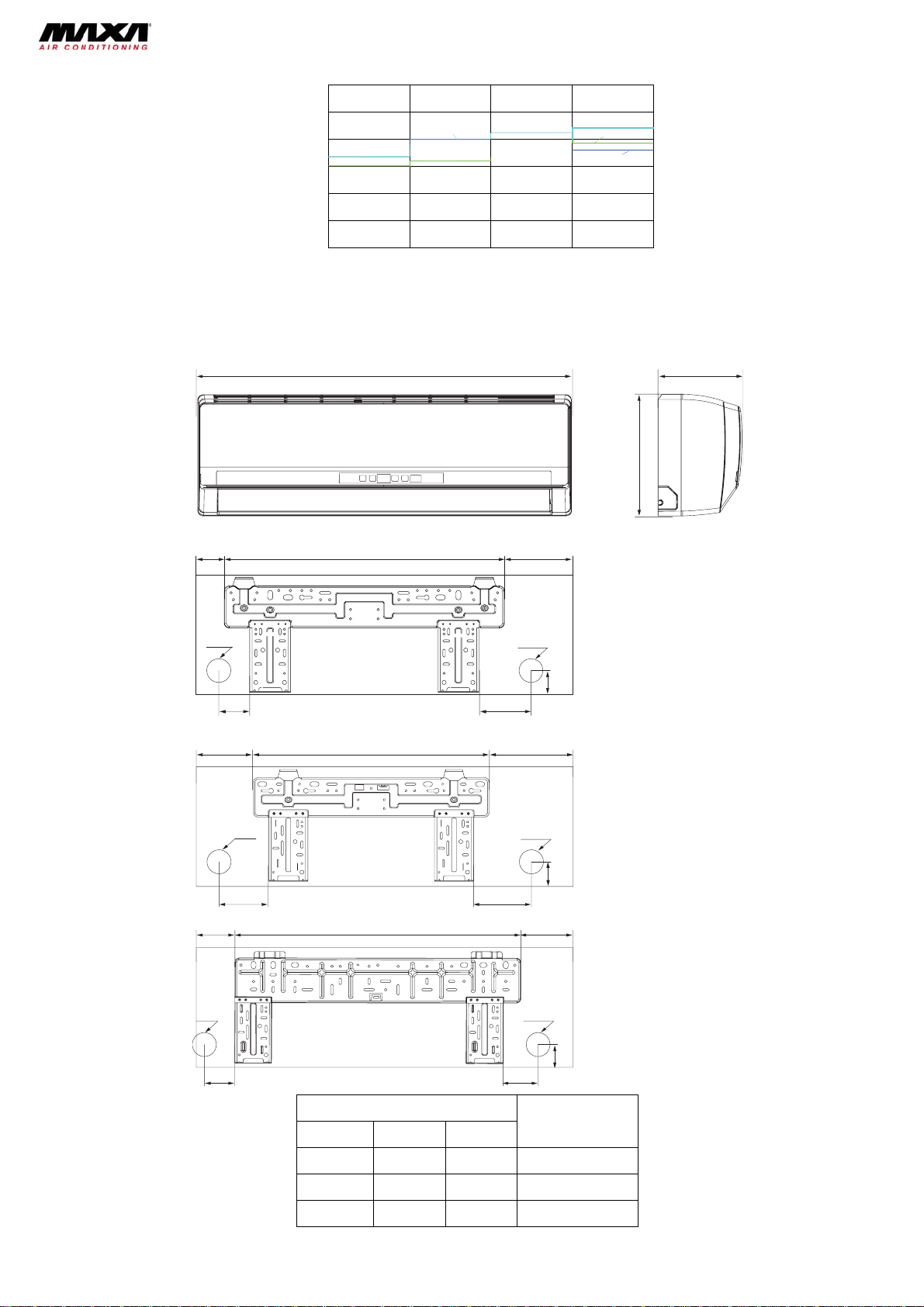
2. Outlines and dimensions
2.1 Indoor units
W
BDLM53A2
BDLM36A2
BDLM26A2
D
H
36
Φ55
Φ55
69
85
941506
BDLM26A2
09K Units
Φ55
40
8704
172542131
BDLM3A2
12K Units
Φ55
50
19469452
BDLM53A2
18K Units
Φ55
Φ55
61183
45
Dimension (mm)
Models
W H D
790 265 174 BDLM26A2
845 275 180 BDLM36A2
940 298 200 BDLM53A2
7
8
92341
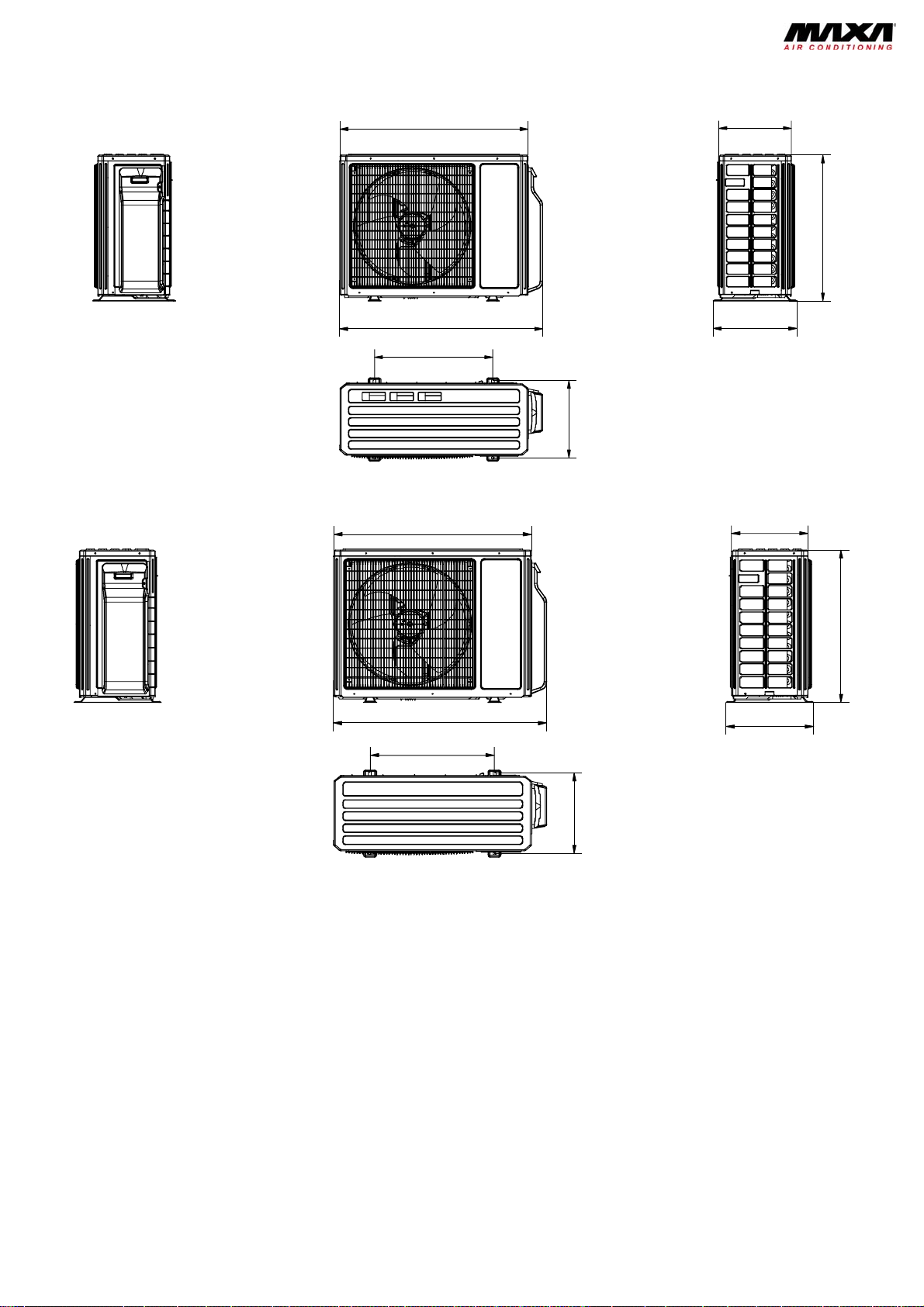
2.2 Outdoor units
a) BD2M53A3
560
700
396963
368
Unit:mm
b) BD3M98A3
924 370
1001
610
427
399
Unit:mm
790
8
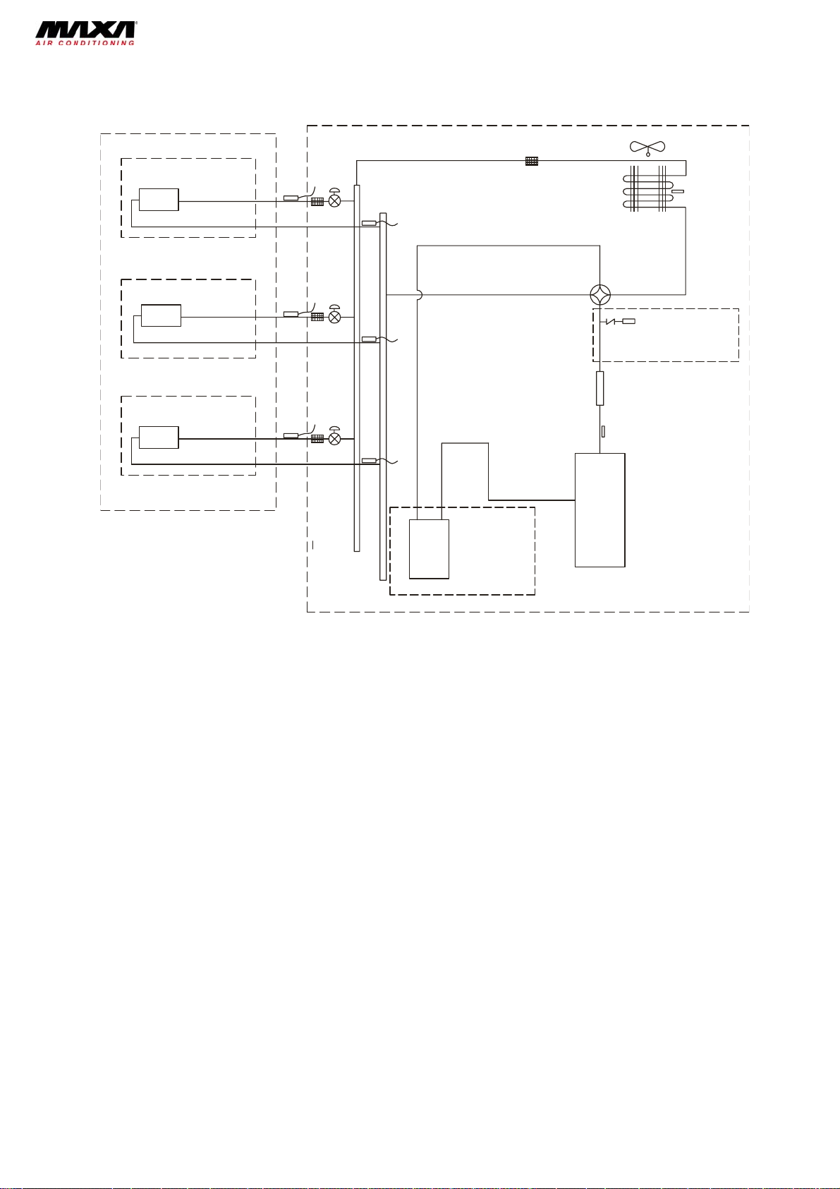
3. Refrigerant circuit
indoor
A heat exchanger
B heat exchanger
C heat exchanger
A3
B3
C3
filter
filter
filter
outdoor
filter
A
1
A2
B
1
B2
C
1
C2
outdoor heat exchanger
fan
4-way valve
SP
high pressure switch
Note: N ot available for 14K/1 8K
model
discharge silencer
discharge temperature
sensor
inverter comp resso r
gas -liquid separator
Note: N ot available for 1 4K/18K m od el
A1:A-unit electronic expansion valve A2:A-unit gas pipe temperature sensor A3:A-unit liquid pipe temperature sensor
B1:B-unit electronic expansion valve B2:B-unit gas pipe temperature sensor B3:B-unit liquid pipe temperature sensor
C1:C-unit electronic expansion valve C2:C-unit gas pipe temperature sensor C3:C-unit liquid pipe temperature sensor
D1:D-unit electronic expansion valve D2:D-unit gas pipe temperature sensor D3:D-unit liquid pipe temperature sensor
9
4. Electrical diagram
4.1 Indoor units
BDLM26A2, BDLM36A2
TUBE
TEM.SENSOR
0
RT2
TUBE
CAP
JUMP
DISP1
RECEIVERAND
DISPLAY BOARD
DISP2
AP1
ROOM
TEM.SENSOR
0
RT1
ROOM
AP2
SWING-UD
M2
SWING
MOTOR
HEALTH-N
BU
COO L PLASMA
GENER ATOR
FAN
MOTOR
M1
PG
COM-OUT
HEALTH-L
PGF
AC-L
RD
N
1BU
3BK
2BN
4YEGN
EVAPORATOR
XT
N(1)
2
3
PE
OUTDOOR UNIT
BU
BK
BN
YEGN
BDLM53A2
NOTE:The parts with broken line is applicable
to the models with COOL PLASMA GENERATOR
TUBE
TEMP.SENSOR
0
RT2
TUBE
ROOM
TEMP.SENSOR
0
RT1
ROOM
CAP
AP2
JUMP
DISP1
DISP2
SWING-UD
FAN MOTOR
M1
PG
PGF
N
COM-OUT
AC-L
HEALTH-NHEALTH-L
1BU
3BK
2BN
XT
N(1)
2
3
4YEGN
PE
EVAPORATOR
BU
BK
BN
YEGN
OUTDOOR UNIT
M2
AP1
RECEIVER AND
DISPLAY BOARD
SWING
MOTOR
RD
COO L PLASMA
GENER ATOR
(optional)
BU
10
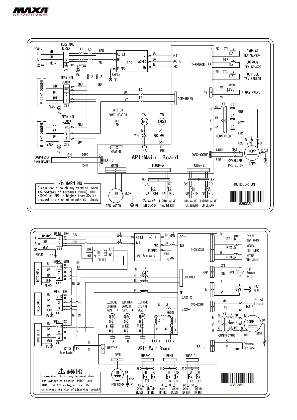
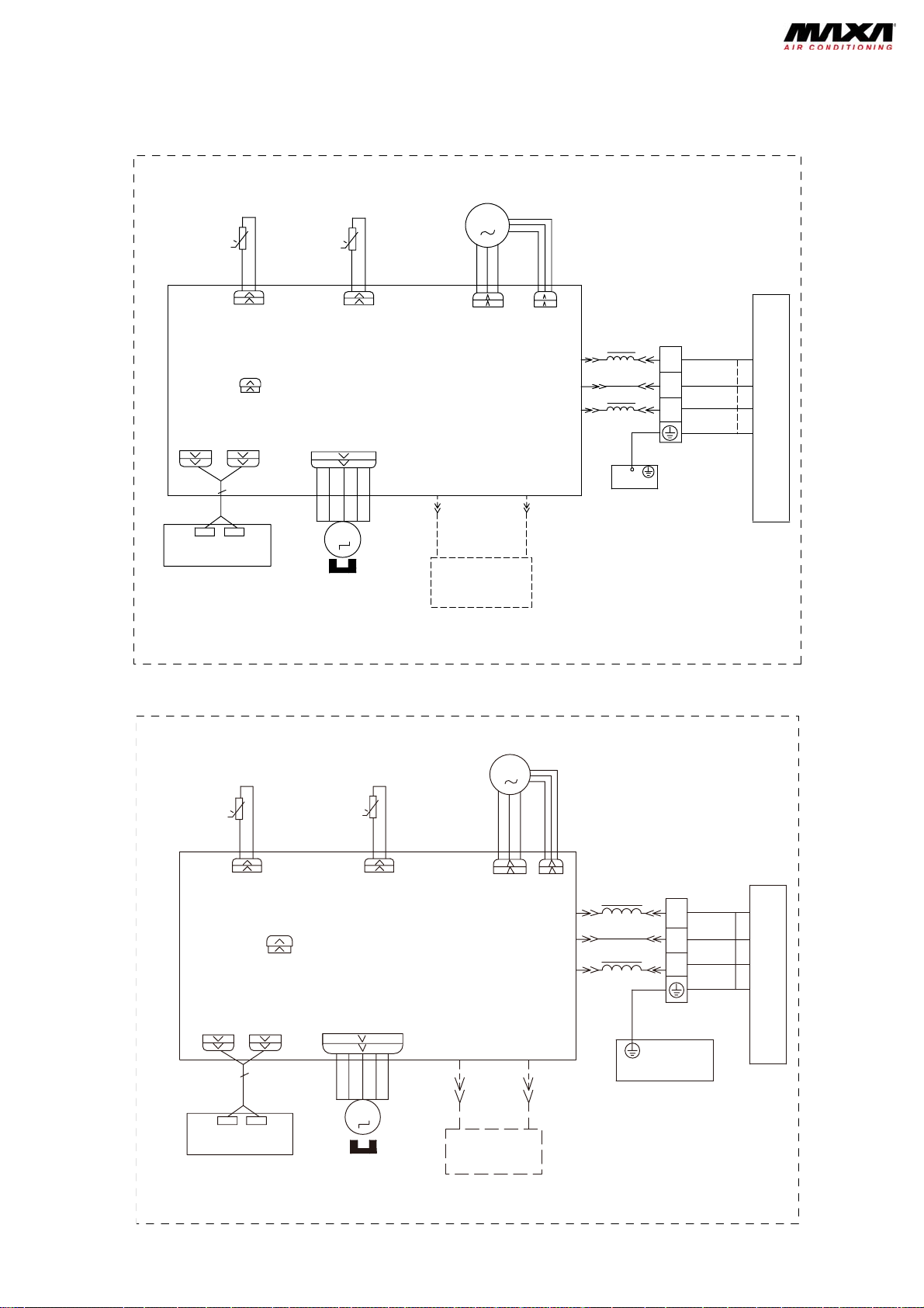
4.2 Outdoor unit
BD2M53A3
BD3M98A3
11
r
r
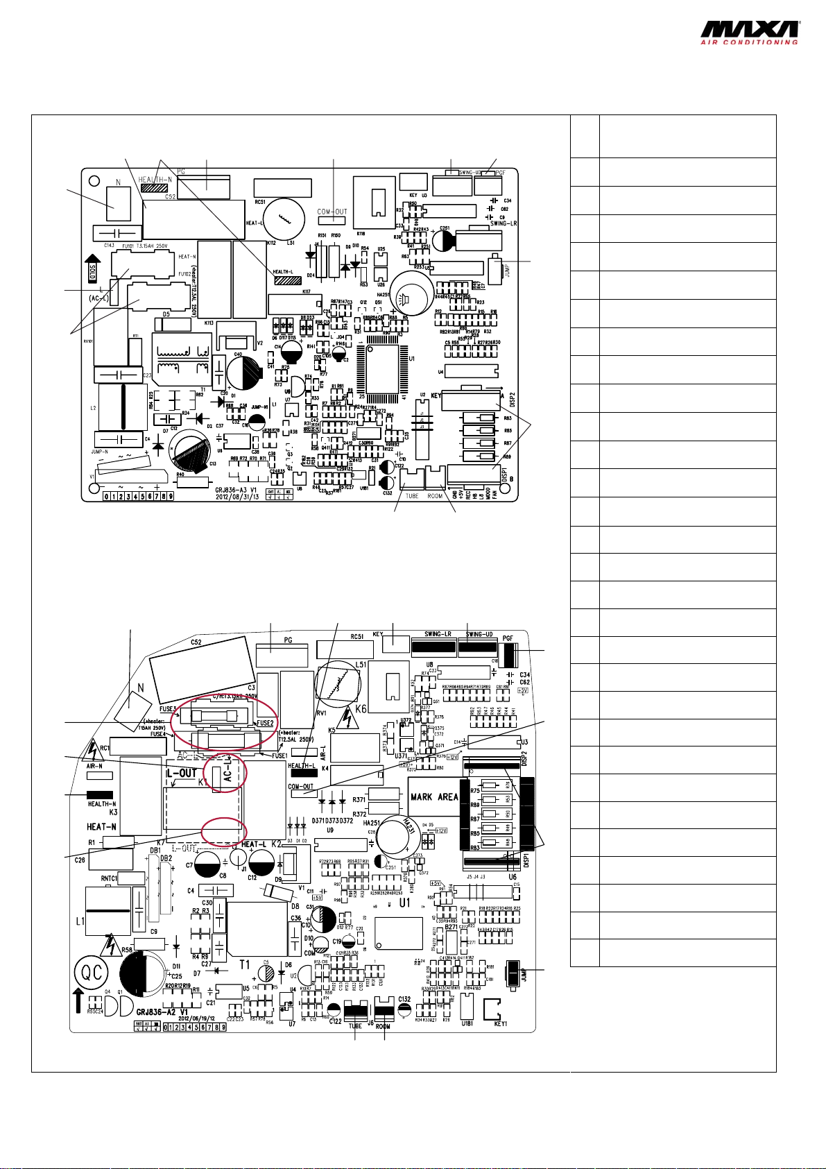
5. Printed circuits
5.1 Indoor units
Models: BDLM26A2, BDLM36A2
Top View
2
1
13
Model: BDLM53A2
Top View
1
853764
1112
234 5
9
10
No Part name
Power supply live wire connector
1
Power supply neutral wire
2
connector
Fan capacitor
3
Health function terminal
4
(optional)
5 Indoor fan wire terminal
Indoor and outdoor unit
6
communication wire terminal
Up & down swing control
7
terminal
Indoor fan feedback terminal
8
Jumper cap
9
Display panel terminal
10
Indoor ambient temperature
11
sensor
Indoor pipe temperature sensor
12
Protective tube
13
No Part name
1 Interface of neutral wire
2 Interface of PG motor
Interface of health function live
3
wire
6
4 Interface of auto button
5 Interface of up and down swing
6 Interface of PG feedback
15
14
13
12
1011
7
8
9
Interface of indoor and outdoor
7
unit communication
Interface of display
8
9 Interface of jumper cap
Interface of ambient temperature
10
senso
Interface of tube temperature
11
senso
Power supply interface of outdoor
12
live wire
Interface of heath function neutral
13
wire
14 Interface of live wire
15 Interface of fuse
12
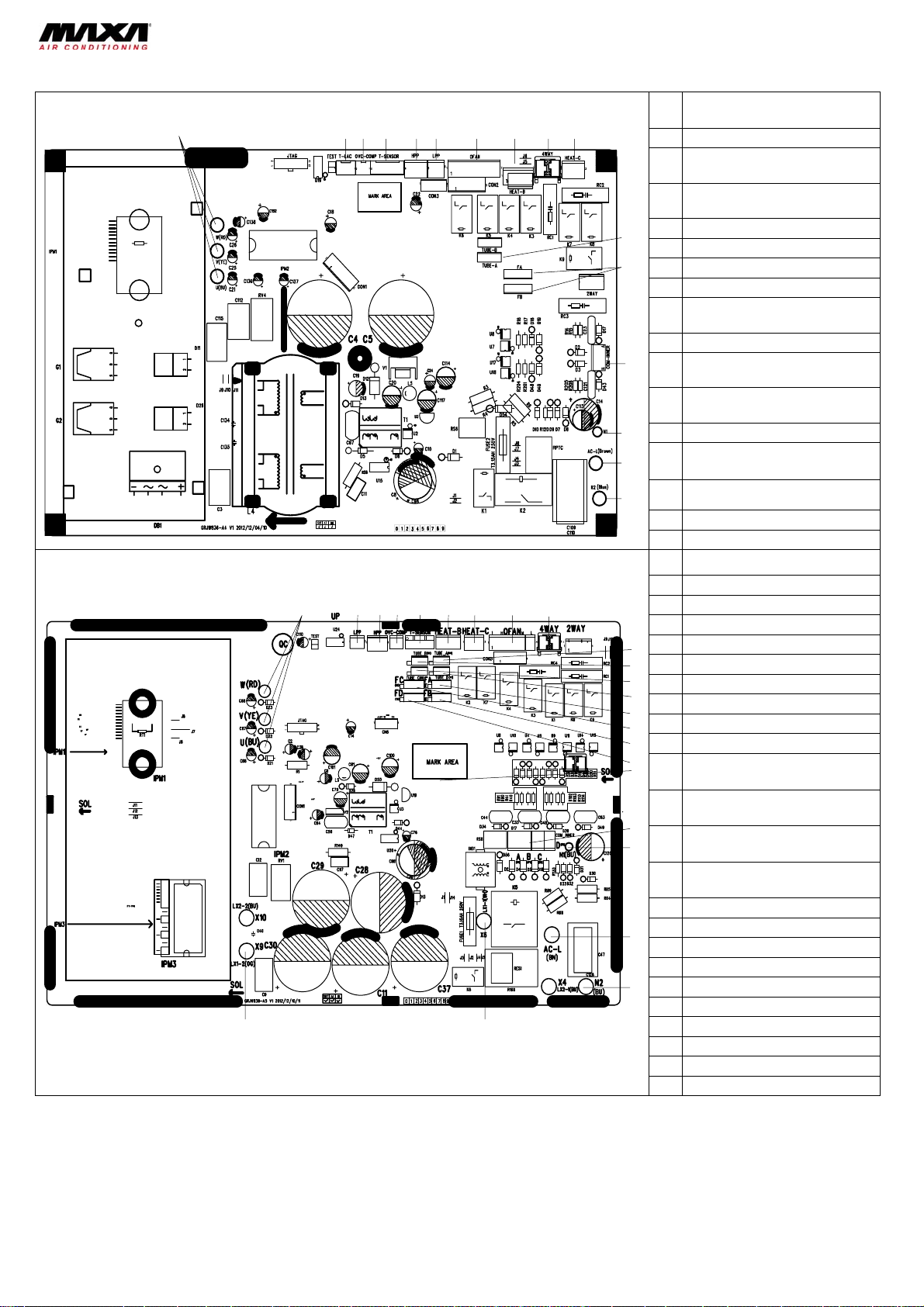
5.2 Outdoor units
3
516
71819
Model: BD2M53A3
1
Models: BD3M98A3
23
23 4 56 7 8 9 10
1
123456 879
22
No Part name
Compressor terminal
1
Temp. sensor terminal of low
2
ambient temp. cooling
Compressor overload protection
3
terminal
4 Outdoor temp. sensor terminal
11
5 High pressure protection terminal
12
13
14
15
16
10
11
12
1
14
1
1
20
21
Low pressure protection terminal
6
Outdoor fan terminal
7
Terminal of chassis electric
8
heating belt
4-way valve terminal
9
Terminal of compressor electric
10
heating belt
Temp sensor terminal of gas
11
valve and liquid valve
Electric expansion valve terminal
12
Terminal of IDU and ODU
13
communication wire
Terminal of communication
14
neutral wire
Live wire terminal
15
Neutral wire terminal
16
No Part name
1 Compressor terminal
High pressure protection
2
3 Low pressure protection
Compressor overload protection
4
5 Outdoor temp. sensor terminal
6 Terminal chassis electric heater
7 Terminal of comp. electric heater
Outdoor fan terminal
8
9 4-way valve terminal
Unit A liquid valve and gas valve
10
temp. sensor
Unit B liquid valve and gas valve
11
temp. sensor
Unit C liquid valve and gas valve
12
temp. sensor
Unit D liquid valve and gas valve
13
temp. sensor
14 Unit A electronic expansion valve
15 Unit B electronic expansion valve
16 Unit C electronic expansion valve
17 Unit D electronic expansion valve
Communication wire with indoor
18
19 Communication neutral wire
20 Live wire
21 Neutral wire
22 Reactor 1
23 Reactor 2
13
 Loading...