


1
Questo manuale è stato creato per scopo informativo. La ditta declina ogni responsabilità per i risultati di una progettazione o di una installazione basata sulle spiegazioni e le specifiche tecniche
riportate in questo manuale. E’ inoltre vietata la riproduzione anche parziale sotto qualsiasi forma dei testi e delle figure contenute in questo manuale.
This manual has been created for informative purpose. The company declines every responsibility for the results of projecting or installation based on the explanations and the technical specifica-
tions given in this manual. Is besides forbidden the reproduction under any form of the texts and of the figures contained in this manual.
Este manual ha sido editado con fines informativos. La empresa se exime de cualquier responsabilidad derivada de un proyecto o una instalación basada en las explicaciones técnicas que figuran
en el manual. Por otra parte, está prohibida la reproducción, incluso parcial, bajo cualquier forma, de los textos y de las figuras contenidas en el manual.
Ce manuel a été créé pour le but informatif. L'entreprise décline toute responsabilité pour les résultats d'un projet ou d'une installation basée sur les explications et les détails techniques rapportés
dans ce manuel. Elle est en outre défendue la reproduction même partielle sous n'importe quel forme des textes et des figures contenues dans ce manuel.
Dieses Handbuch wurde zu Informationszwecken erstellt. Das Unternehmen haftet nicht für die Ergebnisse eines Entwurfs oder einer Installation, die auf den Erklärungen und den technischen
Angaben in diesem Handbuch gründen. Der Nachdruck der in diesem Handbuch enthaltenen Texte und Abbildungen in jeglicher Form ist untersagt.
MANUALE UTENTE-INSTALLATORE PER CLIMATIZZATORI A PARETE TIPO SPLIT
IT
USER’S-INSTALLER'S MANUAL FOR SPLIT TYPE AIR CONDITIONERS
EN
CLIMATIZADORES PARED SPLIT PARA CLIMATIZADORES PARED SPLIT
ES
MANUEL USAGER-INSTALLATEUR POUR CLIMATISEURS MURAL TYPE SPLIT
FR
BENUTZER-INSTALLATIONSANLEITUNG FÜR WAND-SPLIT KLIMAANLAGEN
DE
MODELLI / MODELS / MODELOS / MODELES / MODELLE
ON / OFF MONO ON / OFF DUAL
2600 W 2600 W + 2600 W
3500 W 2600 W + 3500 W
5300 W 3500 W + 3500 W
7000 W
DC INVERTER MONO
2600 W
3500 W
5300 W
7000 W
2
SPLIT MON & MULTI
DC INVERTER SPLIT & ON/OFF
Serie / Series / Serie / Serie
Emissione / Issue
Ausgabe / Emission
Sostituise / Supersade
Ersetzt / Remplace
MUI14000A2205-02
Catalogo / Catalogue / Katalog / Catalogue
12-2012
I prodotti elettrici ed elettronici di eventuale scarto non dovranno essere disposti con i normali rifiuti domestici, ma smaltiti a norma di legge RAEE in base alle direttive Europee 2002/96/CE e successive modifiche
2003/108/CE, informandosi presso il Comune di residenza o presso il rivenditore nel caso in cui il prodotto
venga sostituito con uno analogo.
Possible wasted electrical or electronic devices/products should not be located together with normal domestic
waste, but disposed according to the current WEEE law in compliance with the European Directive 2002/96/
EC and following modifications 2003/108/EC. Please inform yourself at your local Administration or at your
reseller in case the product will be replaced with a similar one.
Los residuos eléctricos y electrónicos no deben ser eliminados junto con los residuos domésticos, pues deben
ser tratados tal como indican las normas sobre RAEE basadas en las Directivas Europeas 2002/96/CE y sus
modificaciones posteriores 2003/108/CE, pidiendo información al ayuntamiento donde se esté domiciliado o
al establecimiento distribuidor del producto, en el caso de que este último sea sustituido por otro similar.
Les produits électriques et électroniques d'éventuel écart ne devront pas être disposés avec les normaux
refus domestiques, mais recueillis aux termes de la loi RAEE sur la base des directives Européennes
2002/96/CE et les suivantes modifications 2003/108/CE, en s'informant auprès de la Commune de résidence
ou auprès du fournisseur dans le cas ou le produit vient d'être substitué avec un autre produit analogue.
Mögliche elektrische und elektronische Abfallprodukte dürfen nicht mit dem Hausmüll deponiert werden,
sondern sind gemäß des Gesetzes zur Entsorgung von Elektro- und Elektronikaltgeräten unter Einhaltung
der Richtlinie des Europäischen Parlaments und des Rates 2002/96/EG und der nachfolgenden Änderungen
in 2003/108/EG zu entsorgen. Im Falle, dass das Produkt mit einem ähnlichen ersetzt wird, ist die örtliche
Gemeinde oder der Wiederverkäufer zu Rate zu ziehen.
12-2011

3
INDICE - INDEX - ÍNDICE - INDEX - INHALTSVERZEICHNIS
ITALIANO . . . . . . . . . . . . . . . . . . . . . . . . . . . . . . . . . . . . . . . . . . . . . . . . . . . . . . . 4
ENGLISH . . . . . . . . . . . . . . . . . . . . . . . . . . . . . . . . . . . . . . . . . . . . . . . . . . . . . . . 20
ESPAÑOL. . . . . . . . . . . . . . . . . . . . . . . . . . . . . . . . . . . . . . . . . . . . . . . . . . . . . . . 36
FRANÇAIS . . . . . . . . . . . . . . . . . . . . . . . . . . . . . . . . . . . . . . . . . . . . . . . . . . . . . . 52
DEUTSCH . . . . . . . . . . . . . . . . . . . . . . . . . . . . . . . . . . . . . . . . . . . . . . . . . . . . . . 68
APPENDICE - APPENDIX - APÉNDICE - APPENDICE - ANHANG
1. IDENTIFICAZIONE - IDENTIFICATION - IDENTIFICACIÓN - IDENTIFICATION - IDENTIFIZIE-
RUNG. . . . . . . . . . . . . . . . . . . . . . . . . . . . . . . . . . . . . . . . . . . . . . . . . . . . . . . . . . . . . . . . . . . . . 84
2.
DIMENSIONI / DIMENSIONS / DIMENSIÓNES / DIMENSIONS / Größe . . . . . . . . . . . . . . . 87
3. SCHEMI ELETTRICI - ELECTRIC SCHEMES - ESQUEMAS ELÉCTRICOS
SCHÉMAS ÉLECTRIQUES - ELEKTRISCHE SCHEMEN . . . . . . . . . . . . . . . . . . . . . . . . . . . . 88
4. LEGENDA - KEY - LEGENDA - LÉGENDE - ZEICHENERKLÄRUNG . . . . . . . . . . . . . . . . . 96

4
ITALIANO

5
INDICE
1. Informazioni importanti . . . . . . . . . . . . . . . . . . . . . . . . . . . . . . . . . . . . . . . . . . . . . . . . . . . . . 6
2. Componenti . . . . . . . . . . . . . . . . . . . . . . . . . . . . . . . . . . . . . . . . . . . . . . . . . . . . . . . . . . . . . . 7
3. Display . . . . . . . . . . . . . . . . . . . . . . . . . . . . . . . . . . . . . . . . . . . . . . . . . . . . . . . . . . . . . . . . . . 7
4. Telecomando . . . . . . . . . . . . . . . . . . . . . . . . . . . . . . . . . . . . . . . . . . . . . . . . . . . . . . . . . . . . . 8
5. Manutenzione . . . . . . . . . . . . . . . . . . . . . . . . . . . . . . . . . . . . . . . . . . . . . . . . . . . . . . . . . . . 12
6. Operazioni e prestazioni . . . . . . . . . . . . . . . . . . . . . . . . . . . . . . . . . . . . . . . . . . . . . . . . . . . 13
7. Problemi e le loro cause . . . . . . . . . . . . . . . . . . . . . . . . . . . . . . . . . . . . . . . . . . . . . . . . . . . 14
8. Installazione. . . . . . . . . . . . . . . . . . . . . . . . . . . . . . . . . . . . . . . . . . . . . . . . . . . . . . . . . . . . . 15
6
1. INFORMAZIONI IMPORTANTI
Non effettuare operazioni che implichino l’apertura
dell’apparecchio.
Folgorazione per presenza di componenti sotto tensione.
Lesioni personali per ustioni per presenza di componenti
surriscaldati o per ferite per presenza di bordi e protuberanze taglienti.
Non effettuare operazioni che implichino la rimozione
dell’apparecchio dalla sua installazione.
Folgorazione per presenza di componenti sotto tensione.Lesioni personali per ustioni da raffreddamento per fuoriuscita
di gas dalle tubazioni scollegate.
Non avviare o spegnere l’apparecchio inserendo o staccando la spina del cavo di alimentazione elettrica.
Folgorazione per danneggiamento del cavo, o della spina, o
della presa.
Non danneggiare il cavo di alimentazione elettrica. Folgorazione per presenza di li scoperti sotto tensione.
Non lasciare oggetti sull’apparecchio. Lesioni personali per la caduta dell’oggetto a seguito di
vibrazioni.
Non salire sull’apparecchio. Lesioni personali per la caduta dall’apparecchio.
Non salire su sedie, sgabelli, scale o supportiinstabili
per effettuare la pulizia dell’apparecchio.
Lesioni personali per la caduta dall’alto o per cesoiamento
(scale doppie).
Non effettuare operazioni di pulizia dell’apparecchio
senza aver prima spento l’apparecchio, staccato la
spina o disinserito l’interruttore dedicato.
Folgorazione per presenza di componenti sotto tensione.
Non fare utilizzare l’apparecchio da bambini o persone
inesperte.
Danneggiamento dell’apparecchio per uso improprio.
Non dirigere il usso dell’aria verso piani di cottura o
stufe a gas.
Esplosioni, incendi o intossicazioni per efusso gas dagliugelli di alimentazione amme spente dal usso d’aria.
Non inserire le dita nelle bocchette di uscita aria e nelle
griglie di aspirazione aria.
Folgorazione per presenza di componenti sotto tensione.
Lesioni personali per tagli.
Non bere l’acqua di condensa. Lesioni personali per intossicazione.
Nel caso si avverta odore di bruciato o si veda del fumo
fuoriuscire dall’apparecchio, togliere l’alimentazione
elettrica, aprire le nestre ed avvisare il tecnico.
Lesioni personali per ustioni o inalazioni fumi.
Non effettuare operazioni che implichino la rimozione
dell’apparecchio dalla sua installazione.
Allagamenti per perdita acqua dalle tubazioni scollegate.
Non lasciare oggetti sull’apparecchio. Danneggiamento dell’apparecchio o degli oggetti sottostan-
tiper la caduta dell’apparecchio a seguito del distacco dal
ssaggio.
Non utilizzare insetticidi, solventi o detersivi aggressivi
per la pulizia dell’apparecchio.
Danneggiamento delle parti in materiale plastico o verniciate.
Non utilizzare l’apparecchio per scopi diversi da quello
di un normale uso domestico.
Danneggiamento dell’apparecchio per sovraccarico di funzionamento. Danneggiamento degli oggetti indebitamente
trattati.
Non fare utilizzare l’apparecchio da bambini o persone
inesperte.
Danneggiamento dell’apparecchio per uso improprio.
Non dirigere il usso dell’aria verso oggetti di valore,
piante o animali.
Danneggiamento o deperimento per eccessivo freddo/
caldo,umidità, ventilazione.
Non usare il condizionatore per molto tempo in condizioni di umidità superiore all’80%.
Danneggiamento oggetti per gocciolamento eccessiva condensa dall’apparecchio.
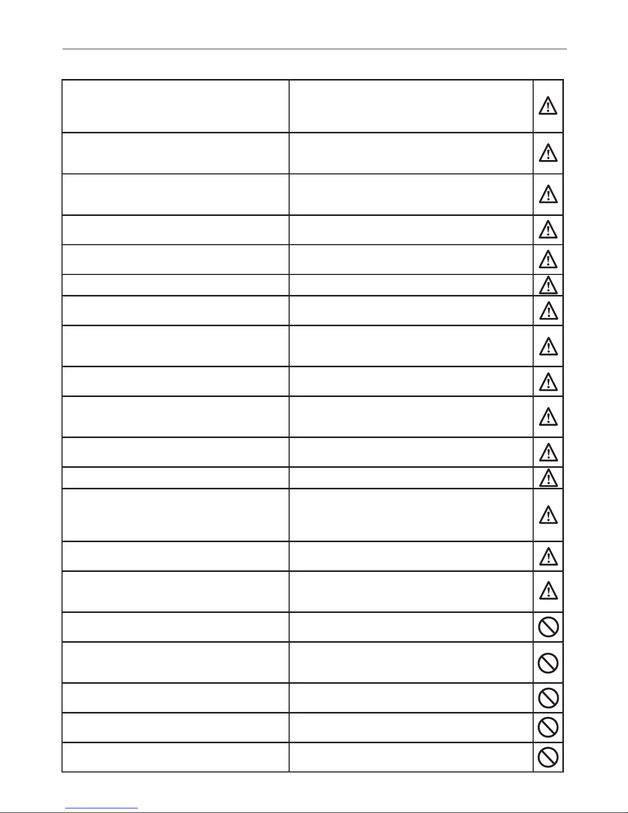
NORMA : RISCHIO :
7
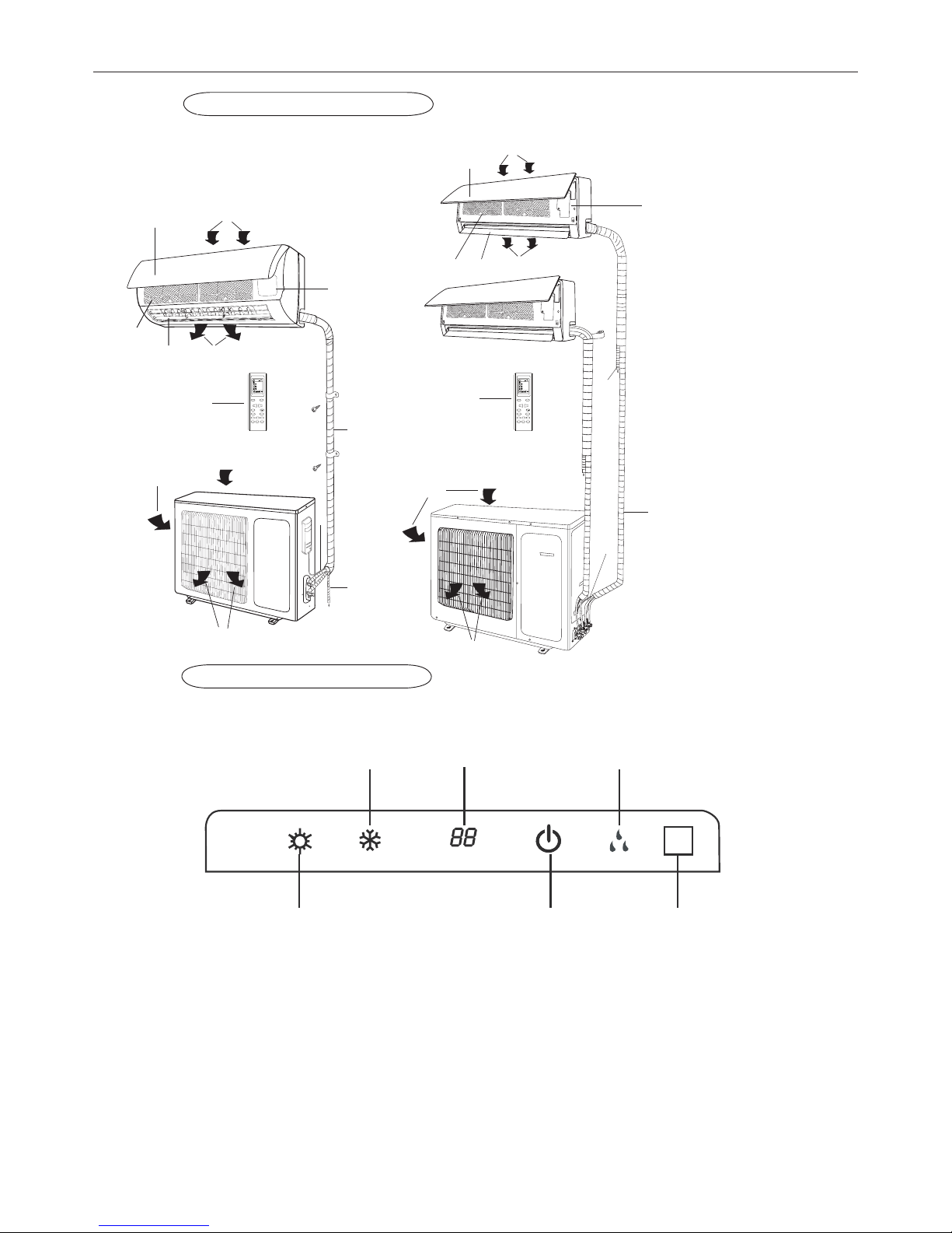
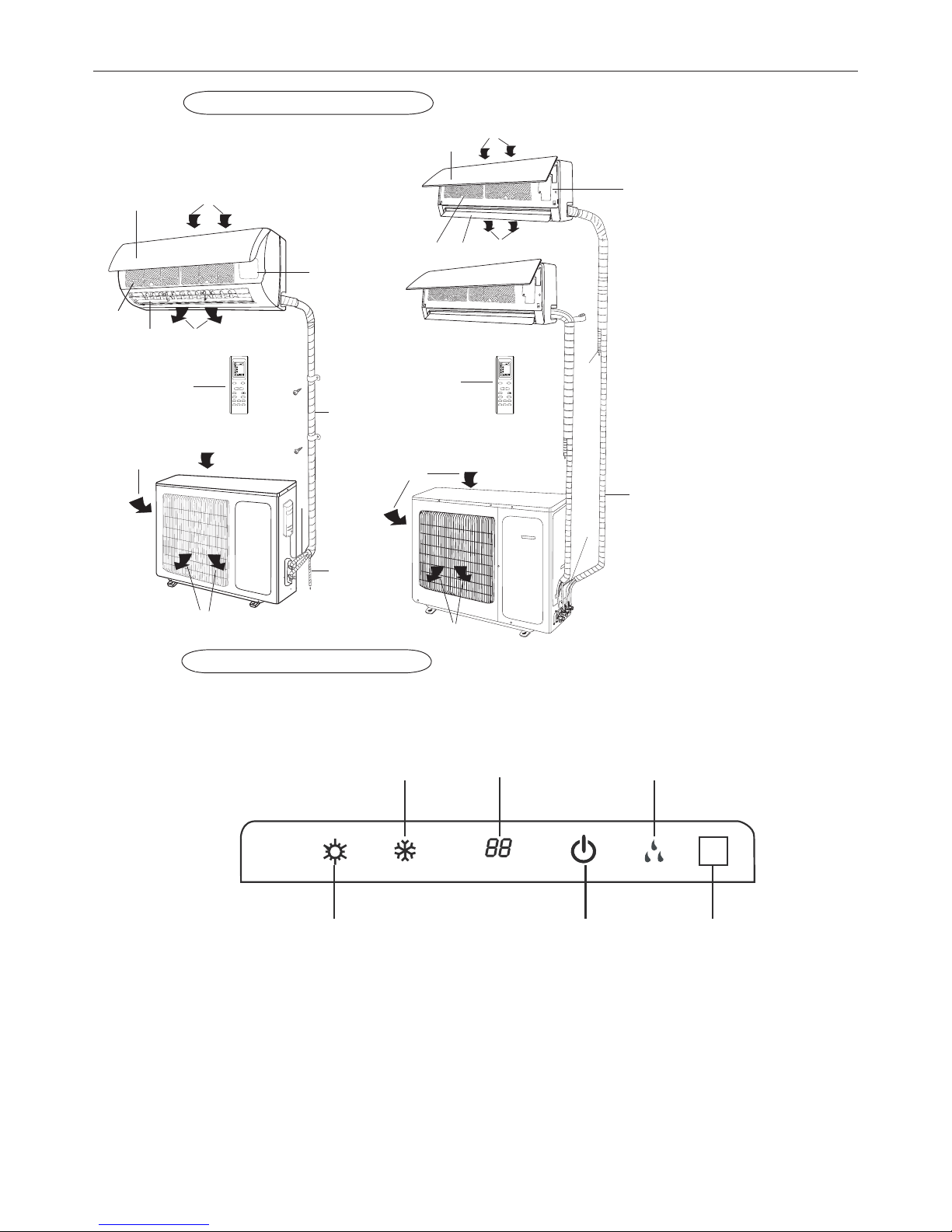
2. COMPONENTI
UNITÀ INTERNA
UNITÀ ESTERNA
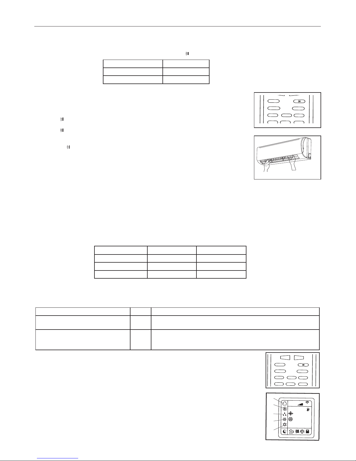
(1) LED recivitore segnale
(2) Indicatore operation
Questo indicatore si illumina durante l'accensione del condizionatore.
(3) Indicatore di riscaldamento
Questo indicatore si accende durante l'operazione del condizionatore in modalità di riscaldamento.
(4) Indicatore di raffreddamento
Questo si illumina durante l'operazione del condizionatore in modalità di raffreddamento.
(5) Indicatore temperatura impostata
Questo indicatore visualizza la temperatura impostata durante il funzionamento del condizionatore.
(6) Indicatore di deumidificazione
Questo indicatore si illumina durante l'operazione del condizionatore in modalità di deumidificazione.
3. DISPLAY
(1)(2)(3)
(4) (5) (6)
(1) Ingresso aria
(2) Griglia frontale
(3) Pannello di controllo
(4) Uscita aria
(5) Alette flusso aria
(6) Filtri aria
(7) Ingresso aria
(8) Tubazioni connessione
(9) Scarico condensa
(10) Uscita aria
(11) Ingresso aria
(12) Telecomando
(1)
(4)
(2)
(6)
(5)
(11)
(9)
(3)
(7)
(10)
(1)
(2)
(4)
(5)
(6)
(11)
(12)
(12)
(10)
(8)
(7)
(3)
(9)
(8)
23
8888:
FAN
HOUR
ON-OFF
AUTO
OPER
FAN
CLOCK
TIMER OFF
TIMER ON
LIGHTSLEEPTURBO
ON/OFF MODE
BLOW TEMP
°F
°C
+
-
23
8888:
FAN
HOUR
ON-OFF
AUTO
OPER
FAN
CLOCK
TIMER OFF
TIMER ON
LIGHTSLEEPTURBO
ON/OFF MODE
BLOW TEMP
°F
°C
+
-

8
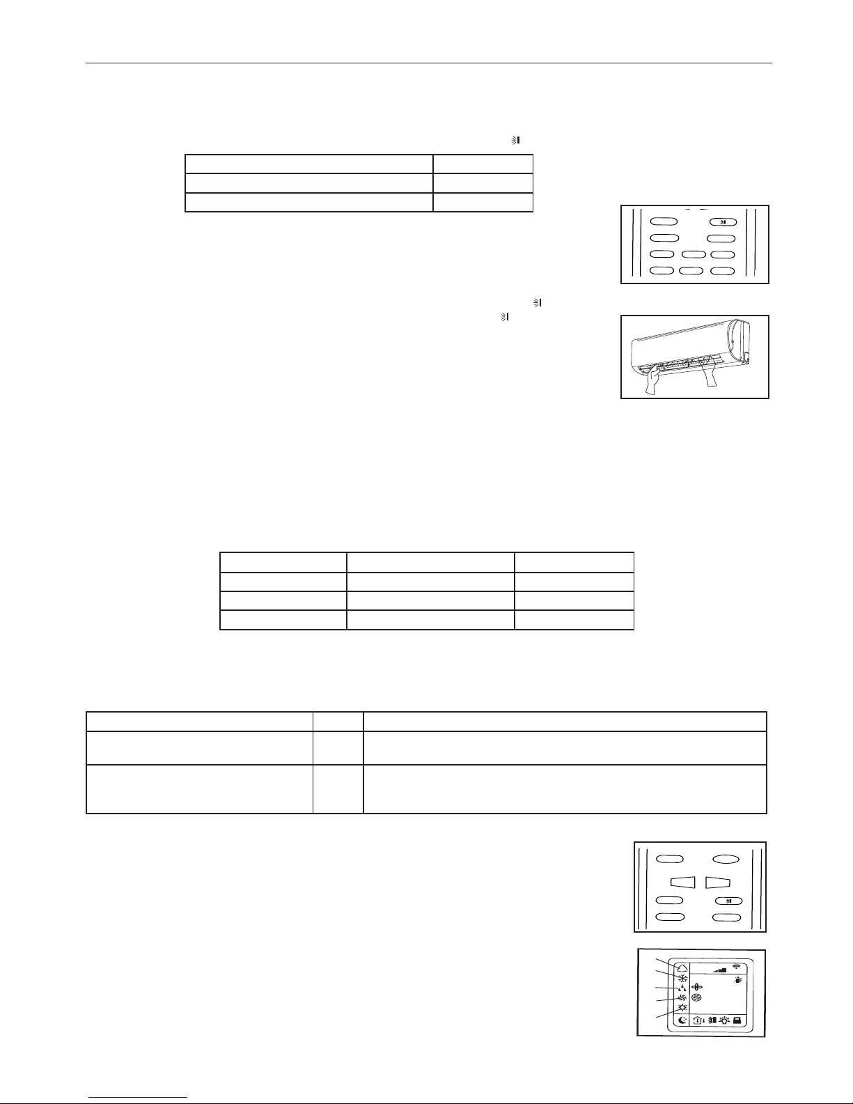
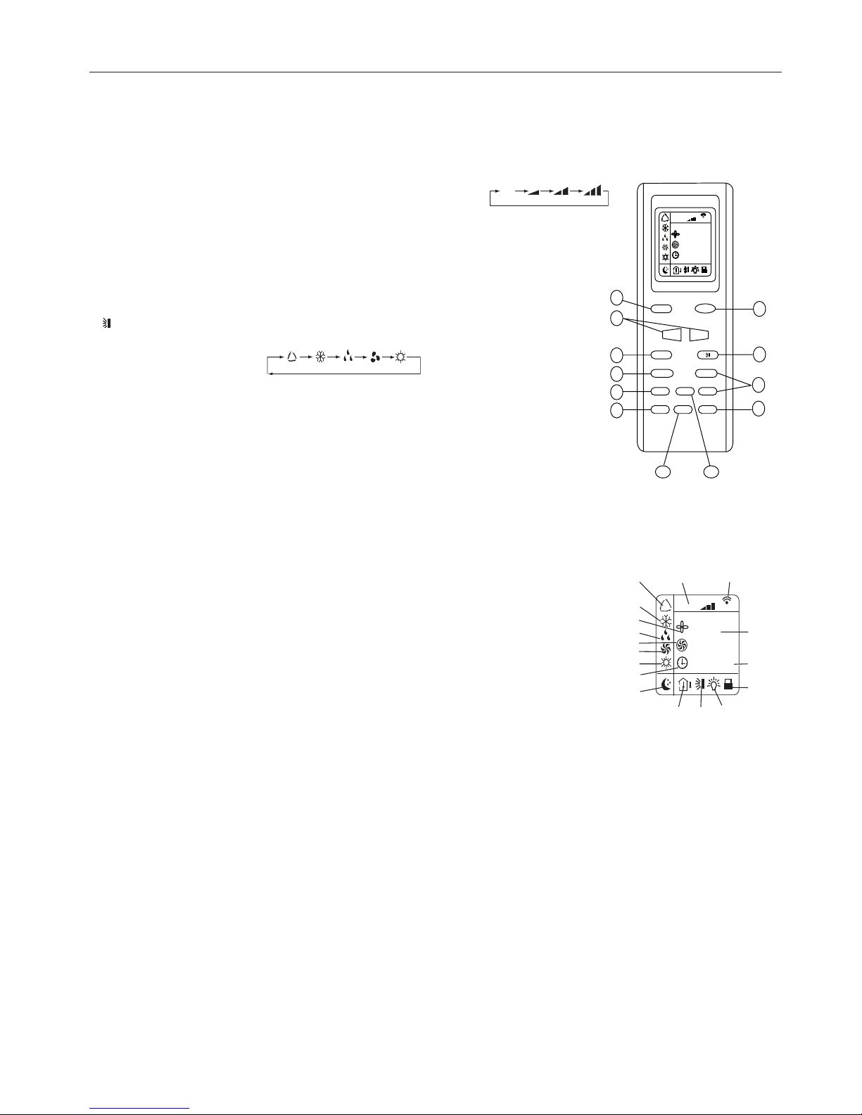
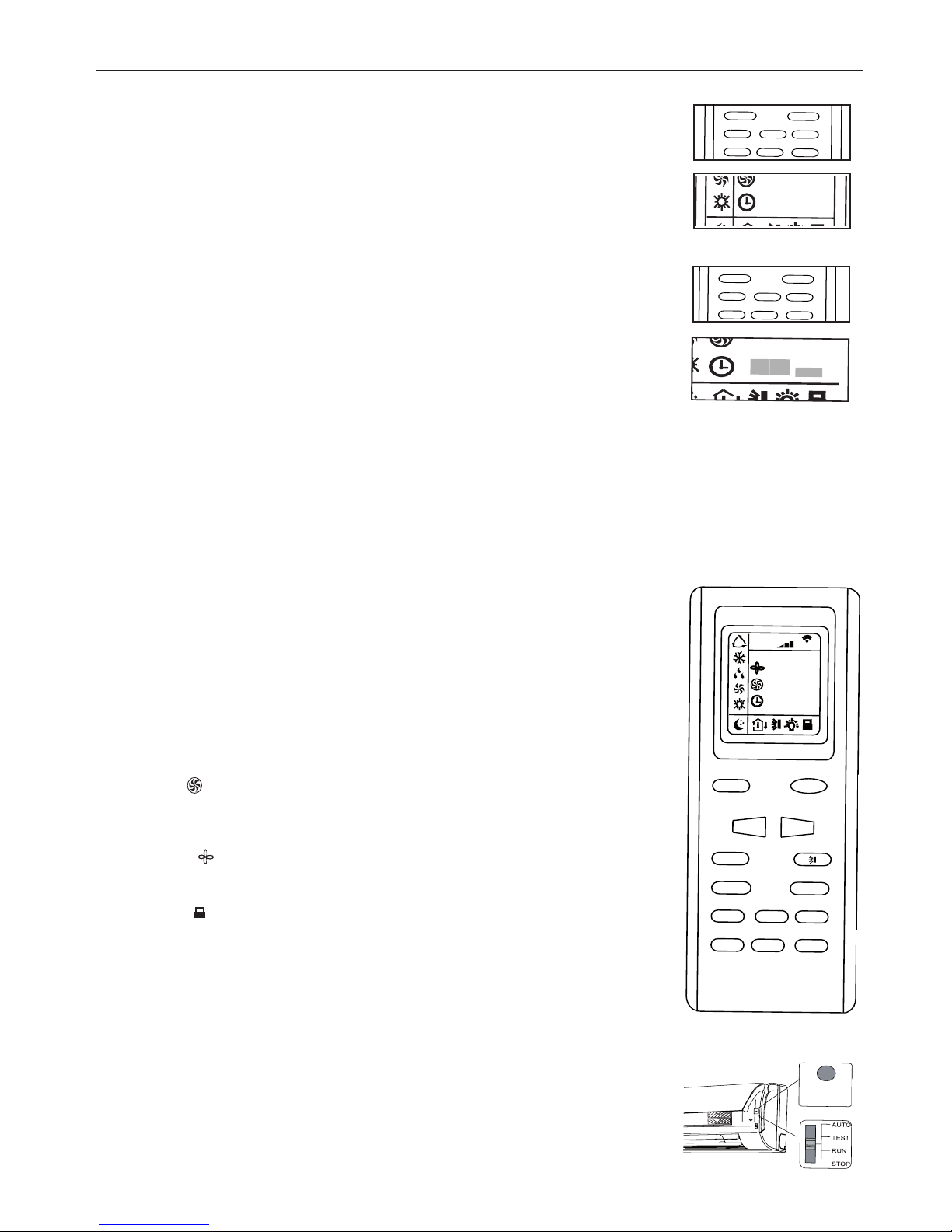
DESCRIZIONE FUNZIONI DEI TASTI DEL TELECOMANDO
1) Tasto ON/OFF, consente di spegnere e accendere il condizionatore.
2) Tasto per impostazione temperatura, consentono di regolare la temperatura ambiente interna: "+" ne imposta l'aumento, "-" ne
imposta la diminuzione.
3) Tasto FAN permette di selezionare la velocità della ventilazione: automatica - bassa - media - alta.
4) Tasto CLOCK consente di impostare l’orario corrente.
5) Tasto BLOW attivo solo nei modi di funzionamento RAFFREDDAMENTO e DEUMIDIFICAZIONE.
6) Tasto TURBO attiva/disattiva la modalità di raffreddamento e riscaldamento veloce.
7) Tasto notte SLEEP, usato per impostare/cancellare la modalità Sleep, indipendentemente dal
modo in cui sta operando il condizionatore.
8) Tasto TEMP permette di visualizzare sul display dell’unità la temperatura di set point o ambiente.
9) Tasto LIGHT accendere o spegnere il display dell’unità.
10
) Tasti di selezione TIMER.
11) Tasto per attivare/disattivare il movimento automatico del deflettore d'aria.
12) Tasto MODE, permette di selezionare la modalità di funzionamento: AUTO - COOL-
DRY - FAN - HEAT:
AUTO: Permette di selezionare automaticamente la modalità di funzionamento
più opportuna in relazione alla temperatura ambiente iniziale (modalità automatica).
COOL: L’unità si avvia quando la temperatura impostata è piu’ bassa della temperatura
ambiente.
DRY: Per deumidificare l'ambiente.
FAN: Pulsante di selezione della velocità del ventilatore o di "selezione automatica
della velocità".
HEAT: L’unità si avvia quando la temperatura impostata è piu’ alta della temperatura
ambiente.
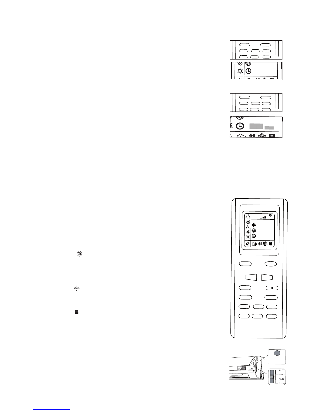
DESCRIZIONE INDICATORI DEL DISPLAY
1) Indicatore modalità AUTO.
2) Indicatore modalità
RAFFREDDAMENTO.
3) Indicatore modalità
BLOW.
4) Indicatore modalità
DEUMIDIFICAZIONE.
5) Indicatore modalità
TURBO.
6) Indicatore modalità
VENTILAZIONE.
7) Indicatore modalità
RISCALDAMENTO.
8) Indicatore
CLOCK.
9) Indicatore modalità
SLEEP.
10) Indicatore TEMP.
11) Indicatore movimento deflettore.
12) Indicatore LIGHT.
13
) Indicatore LOCK.
14
) Indicatore modalità TIMER ON-OFF.
15
) Indicatore di visualizzazione della temperatura.
16
) Led trasmissione segnale.
17
) Indicatore velocità di ventilazione.
4. TELECOMANDO
4. TELECOMANDO
23
88 88:
FAN
HOUR
ON-OFF
AU TO
OPER
FAN
CLOCK
TIMER OFF
TIMER ON
LIGHTSLEEPTURBO
ON/OFF MODE
BLOW TEMP
°F
°C
+
-
1
2
3
4
5
6
7
8
9
10
11
12
AUTO
23
88 88:
FAN
HOUR
ON-O F F
°C
AUTO
OP ER
1
2
3
4
5
6
7
8
9
10 11 12
14
13
15
1617
DISPLAY
9
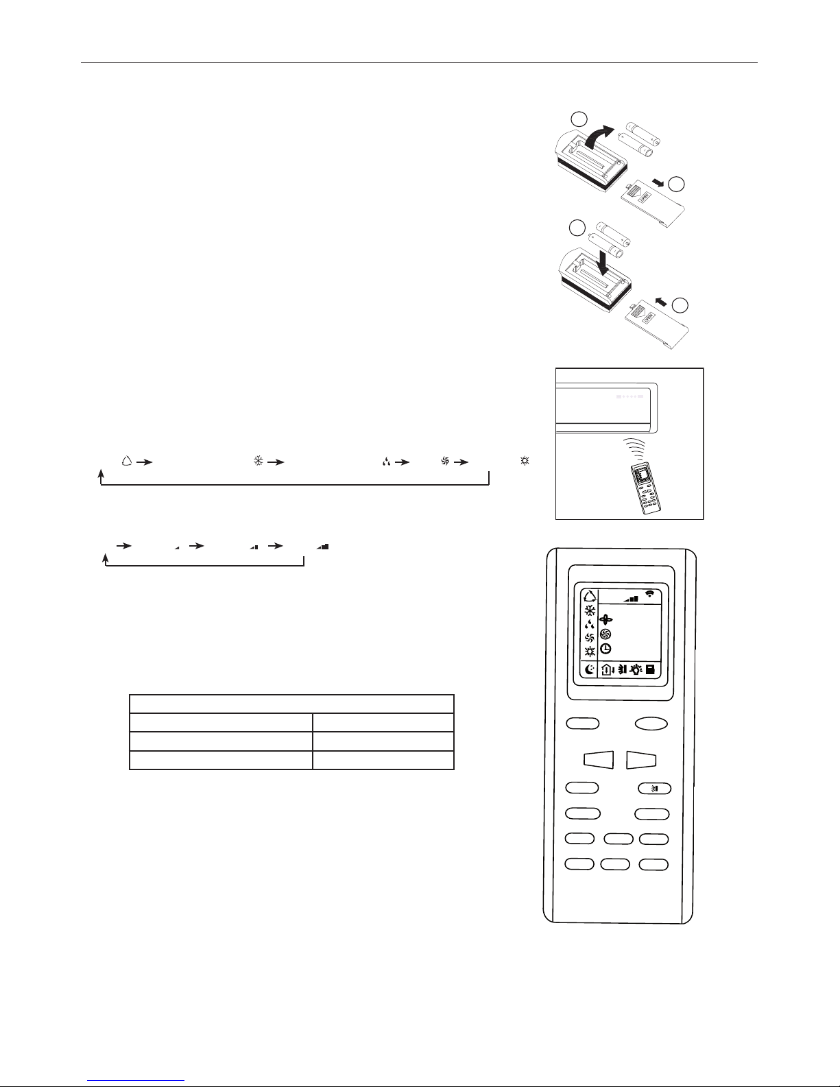
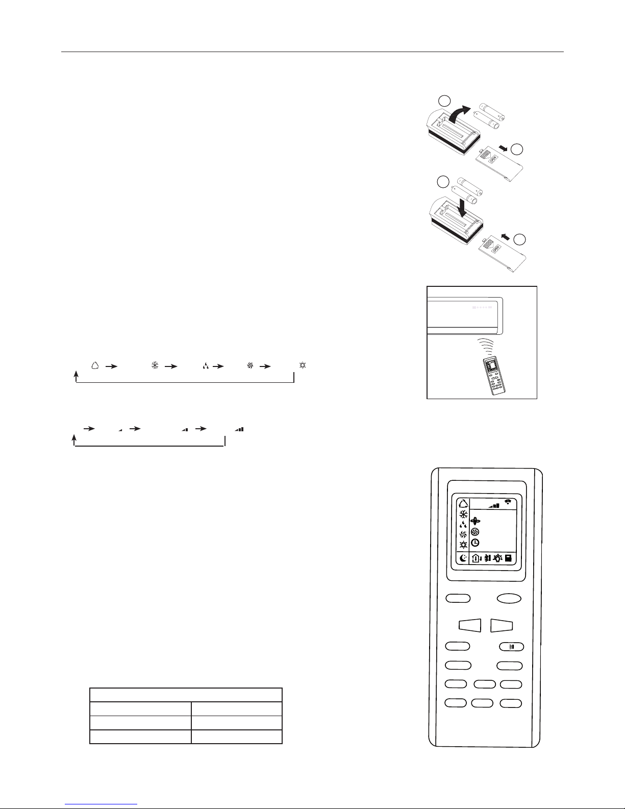
4. TELECOMANDO
Come inserire/sostituire le batterie
Usare due batterie alcaline 1,5 V tipo AAA.
1) Rimuovere il coperchio delle batterie facendolo scivolare nella direzione della freccia.
2) Rimuovere le batterie vecchie e inserire le nuove facendo attenzione ad allineare correttamente le polarità (+) e (-).
Note:
- Non mettere insieme batterie nuove con vecchie o batterie di tipo differente. Ciò
può essere causa di malfunzionamento.
- Se non si usa il telecomando per un lungo periodo le batterie devono essere tolte
per evitare danni causati da eventuali perdite.
- Le batterie vanno sostituite quando non si riceve alcun
"bip" dal l’unità interna
o se l’indicatore di trasmissione sul telecomando non si accende.
Posizionare il telecomando nell’apposito supporto fissato a muro (per assicurare
la trasmissione corretta del segnale).
Modo d’uso
Tenere il telecomando in maniera tale che il segnale possa raggiungere il ricevitore dell’unità interna.
È permessa una distanza massima di ricezione del segnale 7m.
Modalità di funzionamento
(1) Selezione modalità
Ogni volta il tasto "MODE" viene premuto, la modalità di funzionamento è cambiata nella
sequenza seguente:
AUTO ( ) RAFFREDDAMENTO ( ) DEUMIDIFICAZIONE ( ) VENT. ( ) RISCALD. ( )
(2) Modalità ventilazione
Ogni volta il tasto "FAN" viene premuto, la modalità di funzionamento è cambiata nella
sequenza seguente:
Auto
Bassa ( ) Media ( ) Alta ( )
In modalità "VENTILAZIONE", soltanto la "Alta", "Media" e "Bassa" velocità del ventilatore sono disponibili. In modalità di "DEUMIDIFICAZIONE" il ventilatore è automaticamente in "Bassa", il tasto "FAN" è disattivo in questo caso.
2
1
3
4
23
8
88
8
:
F
AN
HO
U
R
O
N
-
O
F
F
A
U
T
O
O
P
E
R
F
A
N
C
L
O
C
K
T
I
ME
R
OF
F
TI
ME
R
O
N
L
I
G
H
T
S
L
E
E
P
T
U
R
B
O
O
N
/
O
FF
M
O
D
E
B
L
O
W T
E
M
P
°
F
°
C
+
-
23
88
88
:
FA
N
HO
UR
ON
-O
FF
AU
TO
OP
ER
FA
N
CLO
CK
TI
MER
OF
F
TI
MER
ON
L
IGH
T
SLEEP
T
URB
O
ON/OFF
MO
DE
BLOW
T
EMP
°F
°C
+
-
(3) Temperatura d'impostazione
Ogni volta che si preme il tasto "+" la temperatura impostata aumenta di 1°C.
Ogni volta che si preme il tasto ''-"
la temperatura impostata diminuisce di 1°C.
(4) Accensione
Premere il tasto ON/OFF per accendere l'unità, l'indicatore di funzionnamento (OPER)
dell'unità interna si illumina quando l'apparecchio riceve il segnale.
Note:
- Cambiare modalità durante il funzionamento, a volte l'unità non risponde immediatamente. Tempo d’attesa: 3 minuti.
- All'inizio del funzionamento in modalità di riscaldamento, il flusso d'aria non verrà
scaricato immediatamente. Il flusso d'aria verrà mandato fino a che la temperatura
dello scambiatore di calore dell'unità interna aumenta, dopo circa 2 o 5 minuti.
- Aspettare 3 minuti prima del nuovo avviamento dell'apparecchio.
Gamma temperatura d’impostazione
Riscaldamento, Raffreddamento 16°C - 30°C
Deumidificazione Non disponibile
Ventilazione Non disponibile
10
4. TELECOMANDO
Controllo della direzione del flusso d'aria
Il flusso d'aria verticale è automaticamente regolato ad un determinato angolo in conformità con la modalità di funzionamento
dopo l'accensione dell'unità.
Nota: La direzione del flusso d'aria può anche essere regolata premendo il tasto " " del telecomando.
* Controllo verticale del flusso d'aria (con il telecomando)
Utilizzo del telecomando per la regolazione del flusso d'aria su vari angoli o su un specifico angolo
preferibile.
Oscillazione del flusso d'aria
All’accensione l'aletta di ventilazione dell'aria si regola automaticamente su un’angolo predeterminato.
Per regolare la direzione del flusso d’aria che esce dall’unità interna premere il tasto " "; premendolo una volta, l'aletta continua a
muoversi miscelando l’aria nell’ambiente. Ad una seconda pressione del tasto " ", l'aletta si blocca.
* Controllo orizzontale del flusso d'aria (con le mani)
Girando con le mani le barre di regolazione orizzontale delle alette per cambiare il flusso d'aria come
indicato nella figura.
Nota:
- La figura dell'unità può sembrare differente da quella del condizionatore che avete acquistato.
- Non girare manualmente l'aletta di regolazione verticale per evitare malfunzionamenti. Se quello accade, spegnere l'unità prima
e staccare l'alimentazione, e ricollega di nuovo l'alimentazione.
- È consigliabile non lasciare l'aletta verticale s'inclina verso il basso a lungo tempo in RAFFREDDAMENTO o in DEUMIDIFICAZIONE
per impedire la formazione dell'acqua condensa.
FUNZIONAMENTO AUTO
Durante il funzionamento AUTO, l’unità seleziona automaticamente HEAT, DRY, FAN, COOL in base alla temperatura ambiente.
Attivazione della modalità AUTO:
Prima selezionare sul telecomando la modalità AUTO mediante il tasto MODE.
La modalità di funzionamento e la temperatura di impostazione sono funzione della temperatura ambiente secondo la seguente tabella.
Note:
- Nella modalità AUTO la temperatura non viene visualizzata a display.
- Puo’ succedere che non vi sia scarico d’aria dall’unità interna.
- L’unità potrebbe non partire immediatamente dopo che la modalità di funzionamento è stata cambiata.
MODALITÀ DI FUZIONAMENTO
Utilizzare il tasto "MODE" per selezionare la modalità di funzionamento preferita, scegliendo tra i
seguenti: AUTO - RAFFREDDAMENTO - DEUMIDIFICAZIONE - FAN - RISCALDAMENTO.
1) AUTO Funzionamento Automatico: questa modalità è selezionata premendo il tasto MODE fino a
visualizzare l'indicatore (1). Il condizionatore imposta automaticamente la modalità di funzionamento
(RAFFREDDAMENTO - DEUMIDIFICAZIONE - FAN - CALDO) in base alla temperatura ambiente.
2) RAFFREDDAMENTO: questa modalità si seleziona premendo il tasto MODE fino a visualizzare l'indi-
catore (2). L’unità inizia a funzionare in raffreddamento e si porta velocemente vicino alla temperatura
ambiente impostata.
3) DEUMIDIFICAZIONE: questa modalità si seleziona premendo il tasto MODE fino a visualizzare l'in-
dicatore (3). L’unità inizia a funzionare in raffreddamento e si porta velocemente vicino alla temperatura
ambiente impostata.
4) FAN Funzionamento ventilazione: questa modalità si seleziona premendo il tasto MODE fino a visua-
lizzare l'indicatore (4).
5) RISCALDAMENTO: questa modalità si seleziona premendo il tasto MODE fino a visualizzare l'indicatore (5).
L’unità inizia a funzionare in riscaldamento e si porta velocemente vicino alla temperatura ambiente impostata.
FA
N
CLO
CK
TI
MER
OF
F
TI
MER
ON
L
IGH
T
SLEEPT
URBO
ON/OFF
MO
DE
BL
OW
T
EMP
+
-
FA
N
CLO
CK
TIMER
ON
ON/OFF
MO
DE
+
-
1
2
3
4
5
12 30
:
23
FAN
°C
AU
TO
O
PER
E
Temp. Interna Modalità di funzionamento Temp. impostata
Meno di 21°C
Riscaldamento 18°C
21°C ~ 24°C
Ventilazione /
Più di 24°C
Raffreddamento 25°C
Impressione
Tasto
Procedura di regolazione
Non confortevole a causa del volume inadeguato del flusso.
FAN
La velocità del ventilatore dell’interna si alterna fra alta, media e bassa
velocità ogni volta questo tasto viene premuto.
Non confortevole a causa della direzione
non adeguata del flusso
SWING
Premerlo una volta, l'aletta di regolazione del flusso d'aria verticale oscilla
per cambiare la direzione del flusso d'aria. Premere di nuovo per arrestare
le oscillazioni dell'aletta.
Modalità di funzionamento Direzione flusso
RAFFREDDAMENTO, DEUMIDIFICAZIONE Orizzontale
* RISCALDAMENTO VENTILAZIONE Verso il basso
11
4. TELECOMANDO
IMPOSTAZIONE DELL'OROLOGIO
Premere il tasto CLOCK per regolare l'orologio, utilizzare i tasti di regolazione ''+'' e ''-'' per impostare
l'ora attuale.
- una singola pressione dei tasti, incrementa/decrementa l'orario di 1 minuto.
- una pressione per 1.5 secondi, incrementa/decrementa l'orario di 10 minuti.
IMPOSTAZIONE DEL TIMER
Utilizzare i tasti Timer ON/OFF per impostare la programmazione oraria e quindi l’accensione e lo
spegnimento del condizionatore.
- Come impostare TIMER ON
Premere il tasto TIMER ON per impostare la programmazione oraria dell’accensione del condizionatore.
1) Premere il tasto TIMER ON, la scritta
"ON" lampeggerà sul LCD, dopo di che usare i tasti ''+'' e
''-'' per impostare l’ora desiderata per l’accensione programmata del condizionatore:
- Premere il tasto ''+'' o ''-'' una volta per aumentare o diminuire l’orario di 1 minuto.
- Premere il tasto ''+'' o ''-'' per una durata di 1.5 secondi per aumentare o diminuire l’orario di 10 minuti.
Nota: Se non regolate l'orario in 10 secondi dopo aver premuto il tasto TIMER ON, il telecomando
abbandonerà automaticamente la modalità TIMER ON.
2) Per confermare l'orario desiderato, premere il tasto TIMER ON. Un “suono” può essere sentito, e
la scritta “ON” smette di lampeggiare e l'indicatore del TIMER sull'unità interna si illumina.
3) Il display del telecomando visualizza l'orario attuale subito dopo l'impostazione del TIMER ON.
Come cancellare TIMER ON
Premere di nuovo il tasto TIMER ON, "un suono" può essere sentito dopo di che l'indicatore sparisce, e la modalità TIMER ON
verrà cancellata.
Nota: È analogo per impostare la modalità TIMER OFF per spegnere automaticamente il condizionatore all'ora impostata.
AVVERTENZE
Se impostate la programmazione oraria il telecomando trasmette automaticamente il segnale di accensione o spegnimento all’unità interna agli orari prefissati.
Pertanto mantenete il telecomando in una posizione dalla quale possa trasmettere il segnale correttamente. L’orario possibile di
programmazione è limitato alle 24 ore.
Inizialmente la funzione timer (ON/OFF) viene attivata vicino all’ora attuale.
Il timer non si attiva se allo stesso tempo vengono attivate Timer ON e Timer OFF.
Modalità SLEEP
La modalità "SLEEP" può essere impostata nel funzionamento di riscaldamento o di raffreddamento.
Questa funzione è utile per un ambiente più confortevole quando si va a dormire.
Nella modalità SLEEP:
- La velocità del ventilatore viene impostata sulla bassa.
- La temperatura impostata aumenta (diminuisce) di 1°C se il condizionatore funziona in modalità
di raffreddamento (riscaldamento). Quando la temperatura impostata varia con 2°C la macchina
mantiene la temperatura fino all’ottava ora di funzionamento in modalità “SLEEP”, per poi spegnersi
automaticamente.
Modalità TURBO:
- La modalità TURBO è usata per avviare o arrestare il raffreddamento e il riscaldamento rapido a
massima velocità di impostazione. In questa modalità TURBO.
Si possono regolare la direzione del flusso d'aria e il timer. Se si desidera uscire dalla modalità
TURBO, è sufficiente premere un tasto qualsiasi tra - TURBO, MODE, FAN o ON/OFF, il display
ritorna alla modalità originale.
Modalità BLOW:
Allo spegnimento dell’unità dopo il funzionamento di raffreddamento o deumidificazione se attiva la
ventilazione per 10 minuti della batteria dell’unità in modo da evitare che eventuale condensa residua formi muffe e cattivi odori.
Funzione LOCK:
Premendo contemporaneamente i pulsanti "+" e "-", il telecomando bloccherà l’ultima operazione
programmata. Tutti i pulsanti di comando vengono disattivati, incluso il pulsante di avviamento ON/
OFF. Premendo nuovamente i pulsanti "+" e "-", si riattiveranno le funzioni dei tasti.
Funzione °C / °F: premendo contemporaneamente i tasti "MODE" e "-" ad unità spenta, si potra
scegliere se visualizzare la temperatura in °C e °F.
TASTO DI EMERGENZA
Permette il funzionamento di emergenza in caso di rottura o smarrimento del telecomando. La macchina parte in modalità auto.
FUNZIONE AUTO-RESTART
L’unità è programmata per avviarsi automaticamente in caso di interruzione di corrente elettrica.
AUT
O/ST
OP
25
12
00:
FA
N
HO
UR
ON
-OFF
°C
AU
TO
O
P E
R
ON -OF
F
00
3 :
O
N -OF
F
23
C
23
88
88
:
FA
N
HO
UR
ON
-O
FF
AU
TO
OP
ER
FA
N
CLO
CK
TI
MER
OF
F
TI
MER
ON
L
IGH
T
SL
EEP
T
URB
O
ON
/OFF
MO
DE
BL
OW
T
EMP
°F
°C
+
-
FA
N
CLO
CK
TI
MER
OF
F
TI
MER
ON
L
IGH
T
SLEEPT
URBO
ON/OFF
MO
DE
BL
OW
T
EMP
+
-
F
FA
N
CLO
CK
TI
MER
OF
F
TIMER
ON
L
IGH
T
SL
EEPT
URBO
ON/OFF
MO
DE
BLOW
T
EMP
+
-
E
E
12
5. MANUTENZIONE
Non usare liquidi o aspirapolvere per la pulizia.
Usare un panno soffice e asciutto per pulire l'unità. Per evitare scariche elettriche, mai provare a pulire l'unità spruzzando acqua su di essa.
Pulizia dell’unità interna e del telecomando
* Usare un panno asciutto per strofinare l'unità interna e il telecomando.
* Un panno inumidito con acqua fredda può essere usato per pulire l'unità esterna se è veramente sporca.
* Mai usare un panno umido sul telecomando.
* Non utilizzare panni trattati chimicamente per pulire o lasciare tali materiali sull'unità per molto. Questo può causare danneggiamenti o perdite di colore della
superficie dell'unità.
* Non usare diluenti, solventi, detergenti in polvere o solventi simili per la pulizia.
Questi possono causare la rottura o la deformazione della superficie plastica.
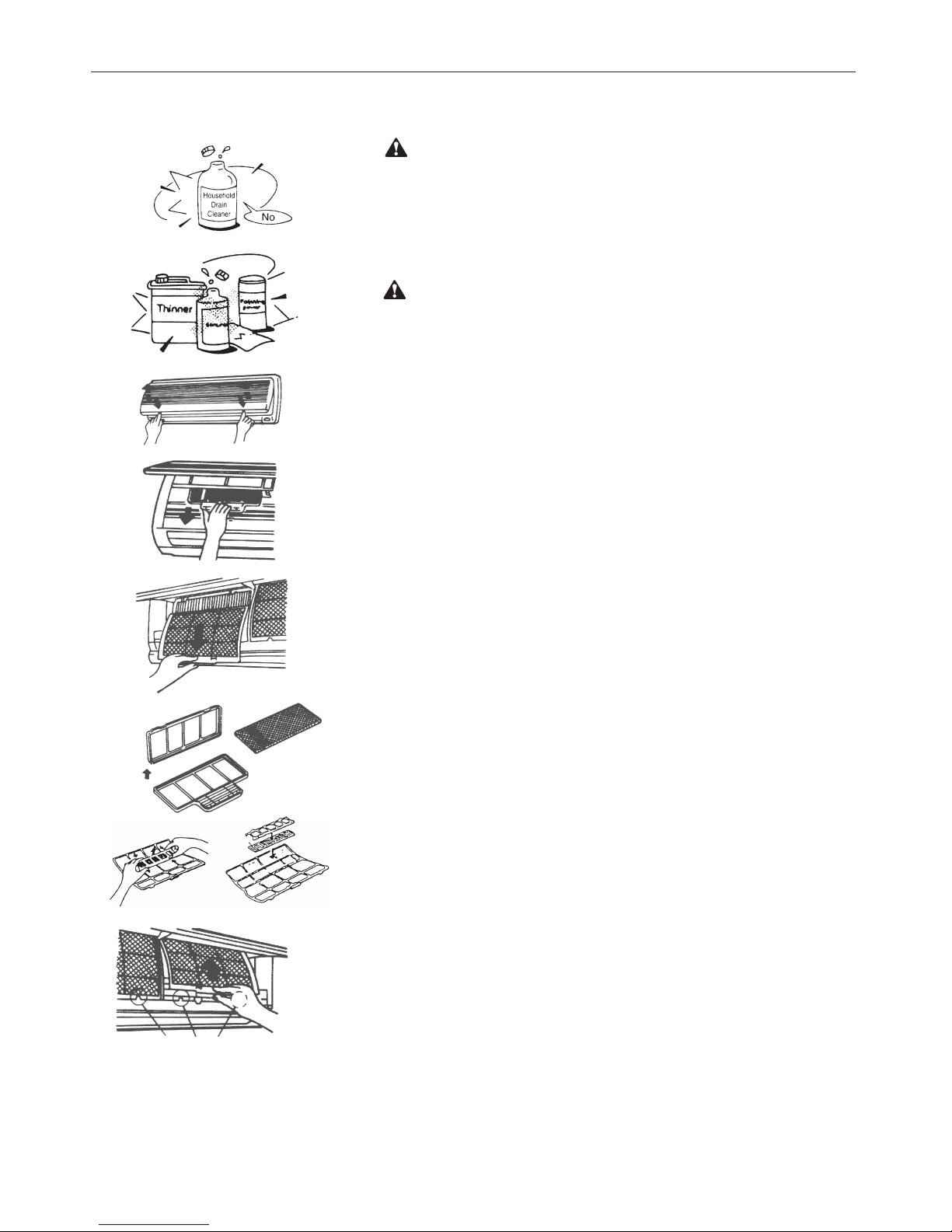
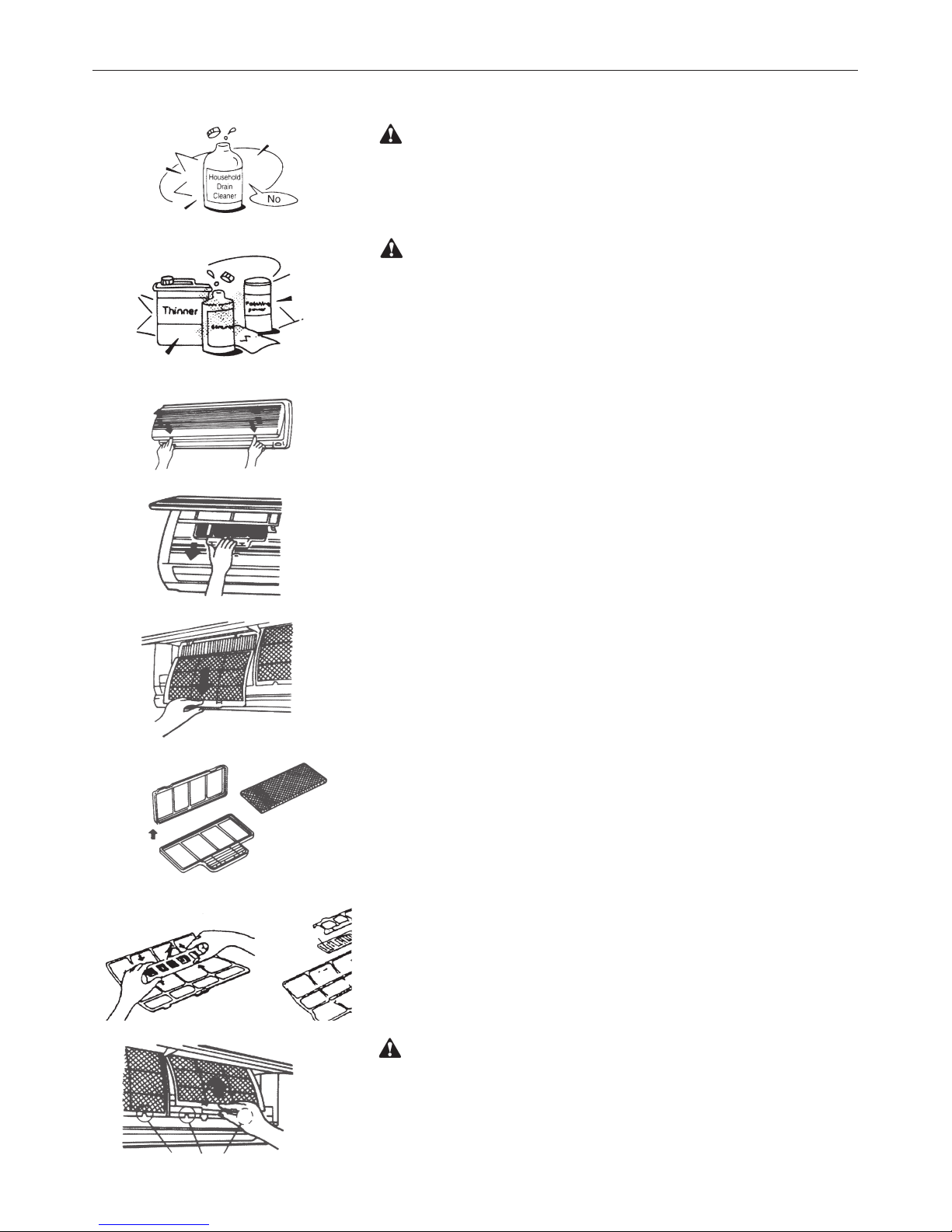
Pulizia del filtro
1) Sollevare dalle estremità il pannello frontale fino a quando non rimane bloccato. Non sollevarlo ulteriormente dopo che si è fermato emettendo un “click”.
2) Prendere il filtro destro e sinistro per la maniglia, sollevarli e farli scivolare al di
fuori del loro supporto.
3) Tirarli verso il basso per rimuoverli completamente.
4) Rimuovere il doppio filtro (carboni attivi e doppio polline).
5) Per lavare, prima di tutto rimuovere il filtro dalla griglia di supporto e immergerlo in acqua con un detergente delicato per 20 minuti, e risciacquar lo dolcemente
(non strofinare). Quindi esporlo per l'asciugatura al sole per almeno 3 ore (mettere il lato nero in alto).
6) Mettere il tessuto del filtro nella cornice del filtro dell'aria e chiudere il coperchio.
7) Mettere il filtro trattamento aria nel condizionatore con il lato nero in alto.
Nota: Pulire il filtro trattamento aria almeno una volta al mese e dopo 4-5 operazioni di pulizia, il tessuto del filtro va sostituito.
8) Usare un aspirapolvere per rimuovere la polvere o lavare il filtro dell'aria.
Nota: Pulire il filtro dell'aria ogni due settimane, perché un filtro sporco può ridurre il rendimento della macchina.
9) Inserire la parte superiore del filtro con trollando che alle estremità entrino
nelle apposite corsie e spingere fino a quando non si blocca.
10) Posizionare la parte inferiore dei filtri nel loro alloggiamento e spingere i due
fermi dove c'è scritto PUSH per chiudere il pannello frontale saldamente.
Manutenzione
Se pensate di non usare l'unità per almeno un mese:
1) accendete la ventola per almeno mezza giornata per asciugare l'interno del
-
l'unità;
2) fermare il condizionatore e staccare la corrente;
3) rimuovere le batterie dal telecomando.
Attenzione
Avvertenze
Generalità

13
6. OPERAZIONI E PRESTAZIONI
I seguenti eventi possono avvenire durante il funzionamento normale.
1. Protezione del condizionatore.
Protezione del compressore
- Il compressore impiegherà 3 minuti per partire dopo l'arresto.
Anti-aria Fredda
- L'unità è studiata per non emettere aria fredda in modalità di riscaldamento, quando lo scambiatore di calore dell'unità interna è in
una delle seguenti situazioni e la temperatura impostata non è stata raggiunta.
A) Quando è appena cominciato il riscaldamento.
B) Sbrinamento.
C) Bassa temperatura di riscaldamento.
Se l'unità esterna è coperta di brina, l'operazione di sbrinamento si attiverà automaticamente (per circa 4-10 minuti) per mantenere
gli effetti del riscaldamento.
- I ventilatori di entrambe le unità interna e esterna, si fermeranno durante l'operazione di sbrinamento.
- Durante l'operazione di sbrinamento, la condensa viene convogliata sul piatto del fondo dell'unità esterna.
2. Fumo generato dall'unità interna
- Può fuoriuscire del fumo dall'unità interna a causa della grande differenza di temperatura tra ingresso ed uscita dell'aria, in moda
lità raffreddamento, e l'alta umidità presente nell'ambiente da raffrescare.
- Può generarsi fumo grazie all'umidità generata dal processo di sbrinamento quando il climatizzatore viene riavviato in modalità
riscaldamento.
3. Piccoli rumori del climatizzatore
Si può udire un rumore tipo "ss" causato dal flusso di refrigerante.
Si può udire un rumore tipo "zz" causato dalla dilatazione della plastica causata dalla variazione di temperatura.
All'accensione si recepisce un rumore dovuto all'apertura delle alette.
4. Della polvere fuoriesce dall'unità interna.
Ciò è normale quando il climatizzatore non è stato usato per un lungo periodo o durante il primo uso dell'unità.
5. Un particolare odore fuoriesce dall'unità interna.
Ciò è causato dall'unità interna che emette degli odori pervasi da materiale di costruzione, da mobilia, o da fumo.
6. Il climatizzatore cambia in modalità VENTILAZIONE dalla modalità di riscaldamento o raffreddamento (per i modelli di
raffreddamento e di riscaldamento soltanto).
Quando la temperatura interna raggiunge la temperatura d'impostazione, il compressore si arresterà automaticamente e l'unità
partirà modalità di ventilazione. Il compressore si riavvierà nuovamente quando la temperatura dell'interna aumenta in modalità di
raffreddamento o raggiunge la temperatura impostata in modalità di riscaldamento (per i modelli di raffreddamento e di riscaldamento soltanto).
7. Dell'acqua può apparire sulla superficie dell'unità interna in modalità di raffreddamento se l'umidità relativa è alta
(superiore all'80%).
Regolare il deflettore orizzontale al massimo dello scarico d'aria e scegliere la velocità alta di ventilazione.
8. In modalità di riscaldamento, il climatizzatore confluisce l'aria calda dall'unità esterna all'unità interna.
Quando la temperatura esterna diminuisce, il calore dell'aria ammessa dal climatizzatore diminuisce. Allo stesso tempo, il carico
calorifico del climatizzatore aumenta a causa della grande differenza tra le temperature esterna ed interna.
9. Funzione d'avviamento automatico
Un'interruzione di corrente durante il funzionamento spegnerà il climatizzatore.
Sui modelli senza dispositivo AUTORESTART, quando la corrente è ristabilita, l'indicatore di FUNZIONAMENTO dell'unità interna
inizia a lampeggiare. Per riavviare l'apparecchio, premere sul tasto ON/OFF del telecomando. Sui modelli muniti di AUTORESTART, quando la corrente è ristabilita, l'apparecchio si riavvia automaticamente con i parametri di funzionemento precedentemente impostati.
10. I lampi o l'utilizzo di un telefono portatile vicino all'apparecchio possono causare malfunzionamenti.
Staccare poi ricollegare l'apparecchio. Per riavviarlo, premere il tasto ON/OFF del telecomando.
6. OPERAZIONI E PRESTAZIONI

14
7. PROBLEMI E LORO CAUSE
Generalità
In caso di malfunzuionamento, disalimentare l'apparecchio e contattare il servizio assistenza più vicino.
L'indicatore di funzionamento, o qualsiasi altro indicatore, si mette a lampeggiare rapidamente (5
Hz) e nonostante lo sconnessione e la riconnessione dell'apparecchio, continua a lampeggiare.
I fusibili o l'interruttore saltano.
L'acqua o altro corpo sconosciuto è penetrato nel climatizzatore.
Il telecomando non funziona o il suo funzionamento non è normale.
Altra situazione anormale
Problema
Errore
Causa
Rimedio
L’unità non parte
Interruzione corrente Attendere il ripristino della corrente.
L'apparecchio è staccato
Verificare se la presa è correttamente
collegata
Il fusibile è saltato
Sostituire il fusibile
Le batterie del telecomando sono
scariche.
Sostituire le batterie
La programmazione è sbagliata
Attendre o annullare la programmazione.
L’unità non climatizza correttamente l’ambiente.
Temperatura impostata non adeguata.
Regolare correttamente la temperatura
Il filtro d’aria è otturato
Pulire il filtro d’aria
Sono bloccati l’ingresso o l’uscità
dell’aria.
Porte o finestre sono aperte
Chiudere le porte o le fenestre
Eliminare ciò che blocca il flusso dell’aria
prima di riavviare l'apparecchio.
I 3 minuti di protezione del compressore sono attivati.
Attendere
Nel caso di presenza dei problemi, si prega di contattare il fornitore locale o il servizio d’assistenza più vicino. Assicurarsi di dare le indicazioni precise che riguardino il tipo di guasto ed il modello dell'apparecchio.
Nota: Non cercare a riparare il climatizzatore da soli. Consultare sempre un centro d’assistenza autorizzato.
15
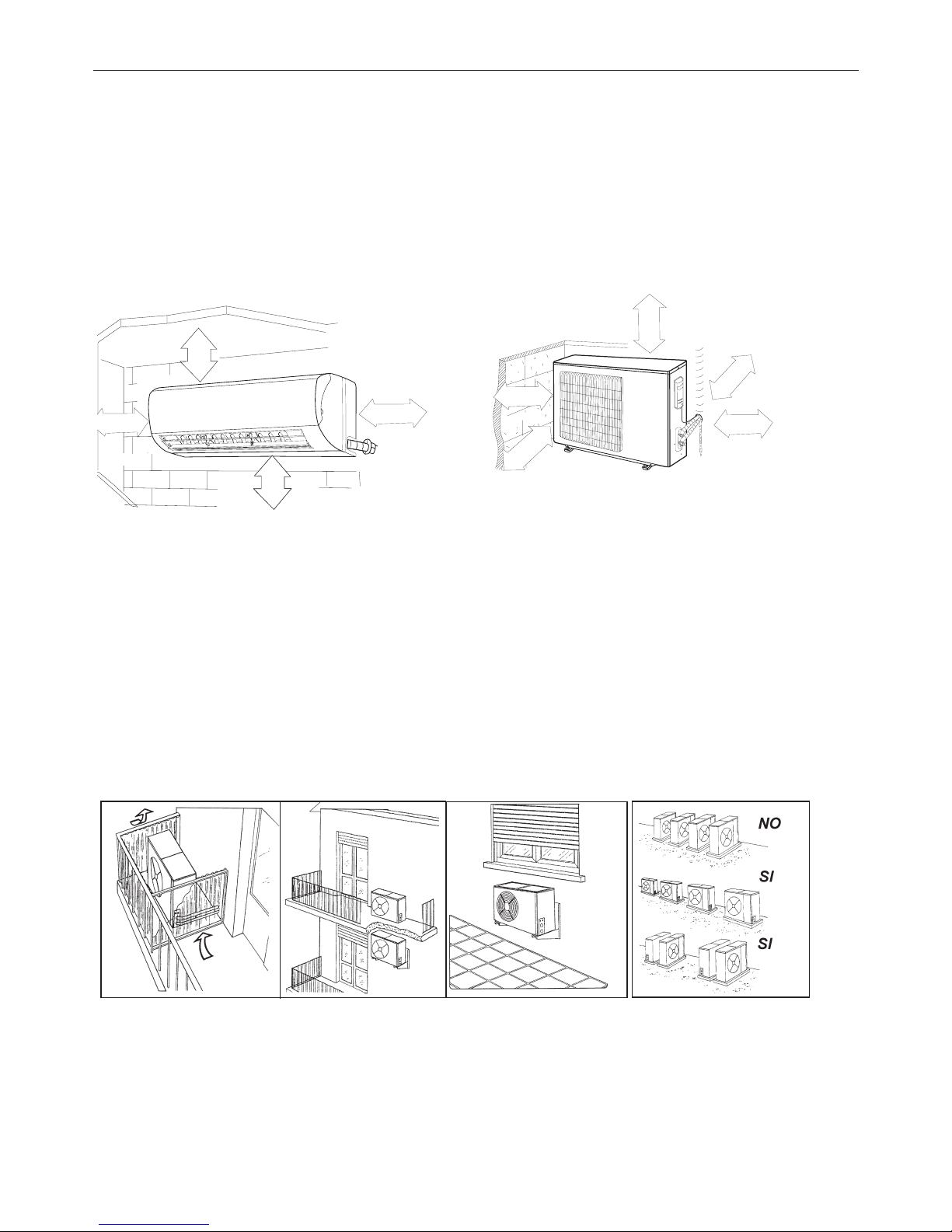
8. INSTALLAZIONE
Unità interna
• Non esporre l'unità interna a calore o a vapore.
• Installare rispettando le distanza indicate, nella parte anteriore e intorno all'unità.
• Assicurarsi che lo scarico condensa funzioni.
• Non installare vicino ad una porta.
• Accertarsi che lo spazio sul lato destro e sinistro dell'unità sia maggiore di 12 cm.
• Prima di eseguire i fori accertarsi di controllare il passaggio di linee elettriche o tubazioni nella parete.
• Il tubo del refrigerante che collega le due unità non deve essere inferiore ai tre metri, onde evitare vibrazioni e rumore eccessivo.
• L'unità interna dovrebbe essere installata sulla parete ad un'altezza di 2-3 m dal pavimento.
• L'unità interna dovrebbe essere installata ad una distanza minima di 15 cm dal softto.
• Se si prolunga il tubo che collega le due unità bisogna sempre aggiungere la quantità di refrigerante corrispondente.
Unità esterna
• Quando l’unità lavora in raffreddamento chiudere tende e nestre per evitare la luce solare diretta.
• Accertarsi che lo spazio nella parte posteriore dell'unità sia maggiore di 30 cm.
La parte anteriore dell'unità dovrebbe avere più di 200 cm di spazio e le parti laterali dovrebbero avere più di 60 cm di spazio.
• Non disporre piante o animali direttamente a ridosso del usso d’aria.
• Tenere conto del peso del condizionatore e posizionarlo in un luogo che non rechi disturbo.
• Posizionare l’unita in un luogo in cui l’aria calda e il rumore non rechino disturbo ai vicini.
• Installare l'unità esterna su una base rigida per evitare l'aumento delle vibrazioni e del rumore.
• Posizionare lo scarico dell’aria in modo che il usso non sia ostacolato in alcun modo.
Nel caso di forte vento, assicurarsi che il ventilatore funzioni correttamente posizionando l'unità longitudinalmente lungo una
parete o usando una schermatura.
• Specialmente nelle zone ventose, installare l'unità in modo che il ventilatore non sia ostacolato.
• Se l’apparecchio deve essere sospeso ad una parete esterna, il supporto deve rispettare le speciche tecniche. Il muro dove l’u-
nità deve essere installata deve essere in mattoni o materiale di consistenza simile altrimenti deve essere rinforzato.
Le staffe di sostegno devono essere stabili e resistenti.
• Assicurarsi che non vi siano ostacoli che impediscano il usso dell’aria.
Installazione sul tetto
• Se l'unità esterna è installata sopra un tetto, assicurarsi di livellare l'unità.
Accertarsi che la struttura del tetto sia appropriata per il montaggio dell’unità.
• Consultare i codici locali per quanto riguarda il montaggio sul tetto.
• Se l'unità esterna è installata sul tetto o sulle pareti esterne, questa può provocare rumore e vibrazioni eccessive e può anche
essere classicata come installazione non idonea al servizio.
2
≤
250 cm
0
2 0
≤
60 cm
≤ 50 cm
≤
15 cm
≤ 15 cm
≤ 15 cm
≤15 cm
≤15 cm
≤ 60 cm
16
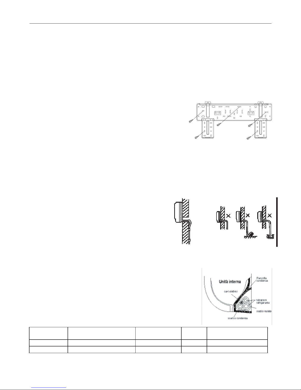
1. Fissaggio della piastra di sostegno
1. Instrallare la piastra di sostegno dell’unità interna orizzontalmente alla parete, e lasciare lo spazio necassario.
2. Se la parete è realizzata con mattoni o materiali simili, eseguire dei fori di 6 mm. Inserire dei tasselli appropriati.
3. Fissare la piastra di installazione sulla parete con otto (8) viti di tipo ”A”. Fissare la piastra di installazione sulla parete forando in
corrispondenza dei punti indicati sulla piastra. (Salvo indicazioni contrarie, le dimensioni sono in mm).
2. Foratura del muro per il passaggio delle tubazioni
1. Servendosi della piastra di installazione determinare la posizione dei fori per le tubazioni.
2. Prestare particolare attenzione quando si fora onde evitare ferimenti.
3. Installazioni delle tubazioni e dello scarico
1. Posizionare il tubo di scolo con la pendenza verso il basso. Non installare il tubo come illustrato.
2. Nel prolungare il tubo di scolo, isolare la parte di collegamento con del nastro iso-
lante, non lasciare che il tubo di scolo sia allentato.
Connessione delle tubazioni
1. Rimuove la piastra posteriore da destra o da a sinistra a seconda del lato scelto per
le tubazioni.
2. Dopo aver attraversato la parete con le tubazioni, piegarle a destra o a sinistra
mantenendo un adeguato spazio (43 mm) come mostrato in figura.
3. Fissare le tubazioni del refrigerante.
Installazione dell’unità interna
1. Far passare le tubazioni attraverso la parete.
2. Mettere la parte superiore dell'unita interna (ed il relativo gancio) a contatto con la piastra, quindi dopo aver spinto l'unità verso il
basso, muoverla per verificare se si è agganciata correttamente.
3. Per facilitare il collegamento delle tubazioni, sollevare l'unità interna e inserire un supporto in gomma tra l'unità e la parete.
Togliere tutto dopo aver connesso le tubazioni.
4. Appoggiare la parte inferiore dell'unità interna alla parete. Quindi, provare a muoverla per verificare se è fissata correttamente.
Installazione dell’unità esterna
Ancorare saldamente l'unità esterna con un bullone e con dadi da 10 o 8 mm
di diametro; orizzontalmente su un supporto rigido.
Montaggio del giunto di scolo.
Inserire la guarnizione nel gomito dello scolo, quindi inserire il giunto dello
scolo nel foro basso della vaschetta dell'unità esterna quindi ruotare di 90°
per fissarlo saldamente. Collegare il giunto con il prolungamento del tubo di
scolo (comprato a parte), nel caso che l'unità esterna subisca perdite d’acqua durante il riscaldamento.
Avvolgimento delle tubazioni
Avvolgere le tubazioni dello scarico e dei cavi elettrici come mostrato nella figura a lato.
Poiché la condensa che si forma durante il funzionamento viene raccolta nell’apposita bacinella, evitare di ostruirla.
AVVERTENZE
• Connettere prima l’unità interna e poi l’unità esterna e fissare saldamente le tubazioni.
• Non lasciare che le tubazioni escano dal retro dell’unità interna.
• Fare attenzione che lo scarico non sia allentato.
• Assicurarsi che le condutture ausiliarie siano state isolate.
• Assicurarsi che lo scarico defluisca correttamente. Fissare lo scarico alle altre tubazioni.
• Evitare che i cavi di alimentazione vengano a contatto con le tubazioni.
8. INSTALLAZIONE
Capacità (W)
Massima lunghezza consentita
dalla tubazione alla spedizione (m)
Lunghezza tubazione
L(m)
Dislivello
H (m)
Quantità refrigerante addizionale
(g/m) , se L(m) > 5 m
2600 W ~ 5300 W
5 15 10 20
7000 W 5 25 10 50
17
8. INSTALLAZIONE
Connessioni elettriche
Collegare il cavo all'unità interna
1. Il cavo di collegamento dell'unità interna ed esterna dovrebbe essere di tipo adeguato.
2. Alzare il pannello dell'unità interna e rimuovere la vite, quindi rimuovere il coperchio.
3. Collegare i cavi secondo i loro contrassegni ai terminali.
4. Avvolgere i cavi dei terminali con nastro isolante, in modo che non si tocchino a vicenda.
Collegare il cavo all'unità esterna
1. Rimuovere il coperchio dell'unità esterna.
2. Collegare i cavi terminali in base ai numeri presenti sulla morsettiera dell’unità.
3. Per impedire l'ingresso di acqua isolare bene i cavi.
4. Fissare i cavi in modo che non vengano in contatto con parti elettriche o in metallo.
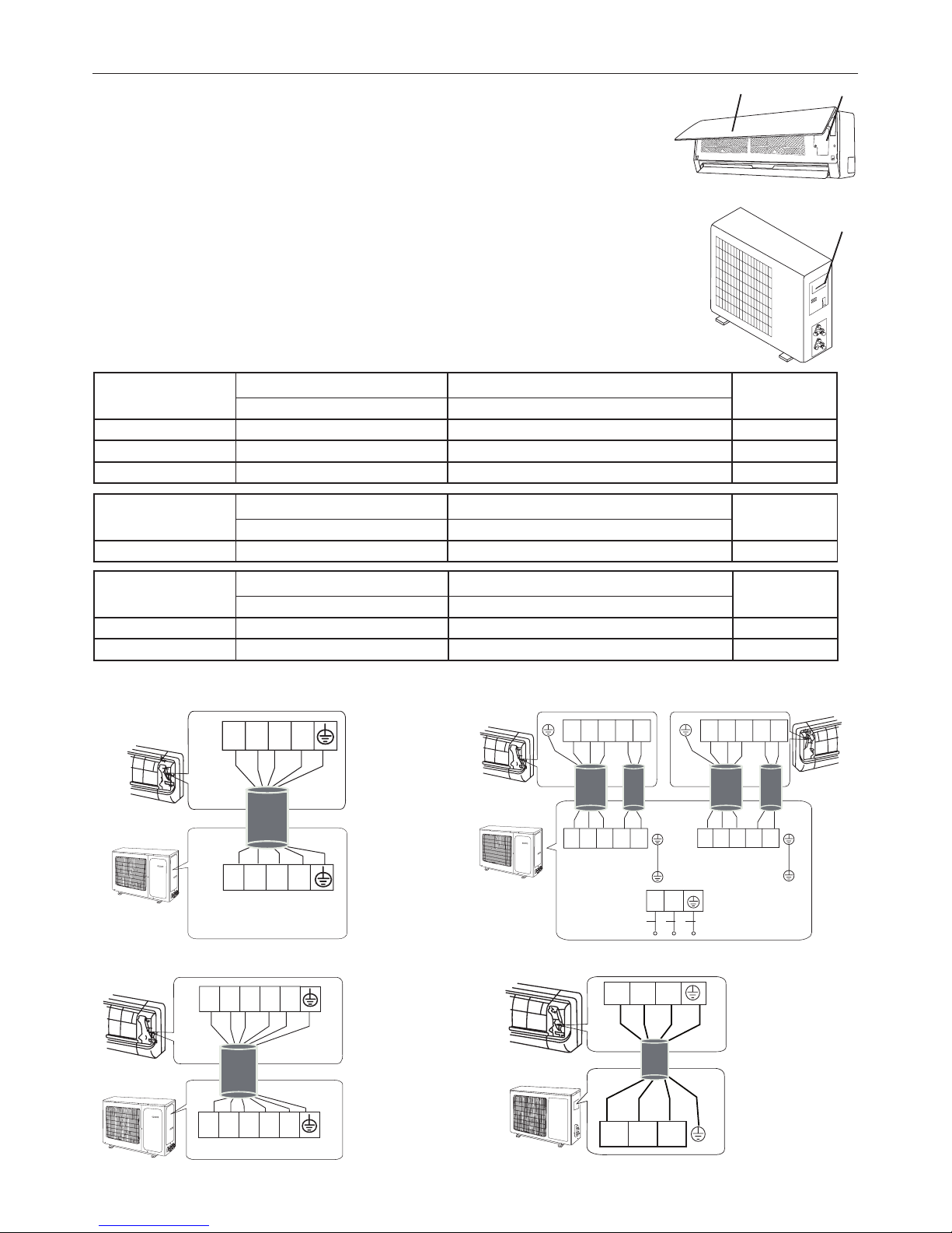
Specifiche Cavi
UNITA' INTERNA
Pannello frontale Morsettiera
Portello di
accesso
morsettiera
UNITA' ESTERNA
ON/OFF MONO
Cavo collegamento alimentazione Cavo collegamento interna-esterna Alimentazione
principale
Sezione Sezione
2600 W, 3500 W 1,5 mm² x 3 1,5 mm² x 5
All'interna
5300 W 2,5 mm² x 3 2,5 mm² x 3 + 1,5 mm² x 2 All'interna
7000 W 2,5 mm² x 3 2,5 mm² x 3 + 1,5 mm² x 3 All'interna
YEGN
YEGN
BU BK VT OG
BU BK VT OG
N(1) 2 4 5
N(1)
2 4 5
YEGN
YEGN
BU BK BN VT
OG
BU BK BN VT
OG
N(1) 2 3 4 5
N(1) 2 3 4 5
BU BK BN VT OG
BU BK BN VT OG
YEGN
YEGN
YEGN
N(1) 2 3 4 5
A UNIT: B UNIT:
N(1)
2 3 4
5
L
N
BU BK BN VT OG
N(1)
2 3 4
5
BU BK BN VT OG
YEGN
N(1) 2 3 4 5
N(1)
2 3
N(1)
2 3
BU
BK BN
BNBKBU
YEGN
YEGN
ON/OFF MONO: 2600 W, 3500 W, 5300 W ON/OFF DUAL: (2 X 2600 W), (2600 W + 3500 W), (2 X 3500 W)
ON/OFF DUAL
Cavo collegamento alimentazione Cavo collegamento interna-esterna Alimentazione
principale
Sezione Sezione
2600 W, 3500 W 1,5 mm² x 3 1,5 mm² x 6
All'esterna
DC INVERTER
MONO
Cavo collegamento alimentazione Cavo collegamento interna-esterna Alimentazione
principale
Sezione Sezione
2600 W 1,5 mm² x 3 1,5 mm² x 4
All'interna
3500 W ~ 7000 W 2,5 mm² x 3 2,5 mm² x 4 All'interna
ON/OFF MONO: 7000 W DC INVERTER MONO: 2600 W, 3500 W, 5300 W, 7000 W
18
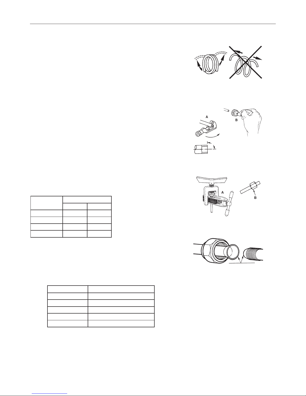
Installazione delle tubazioni per il refrigerante
1. Cartellatura
La causa principale di perdite di refrigerante è dovuta ad un difetto nella cartellatura.
Effettuare le cartelle in modo corretto rispettando le seguenti indicazioni:
A: Tagliare i tubi ed il cavo.
1. Utilizzare tubi con misure adeguate all'unità installata.
2. Misurare la distanza fra l'unità interna ed esterna.
3. Tagliare i tubi ad una lunghezza leggermente maggiore della distanza misurata.
4. Tagliare il cavo 1.5 m più lungo della lunghezza del tubo.
B: Rimozione della bava
1. Rimuovere completamente tutte le bave dalla sezione trasversale
del tubo.
2. La lavorazione deve essere eseguita con l’estremità da lavorare verso il basso in
modo che le bave non cadano dentro al tubo.
C: Collocazione del dado
Rimuovere i dadi fissati sull’unità interna ed esterna, infilarli sul tubo ed eseguire la
cartellatura e la rimozione delle bave come precedentemente indicato. (Non è possibile fissarli dopo la cartellatura).
D: Cartellatura
Fissare saldamente il tubo di rame con un dado della dimensione indicata nella
tabella.
Diam. E (mm) A(mm)
Max. Min
Φ6,35 1,3 0,7
Φ9,52 1,6 1
Φ12,7 1,8 1
Φ16 2 1
Fissaggio del collegamento
• Allineare i tubi. Stringere sufficientemente il dado e stringerlo con due chiavi
come indicato in figura.
PRECAUZIONI
• Una coppia di torsione eccessiva può rompere il dado.
8. INSTALLAZIONE
Diam. Est. (mm) Coppia di torsione (N.m)
Φ 6 15 ~ 20
Φ 9,52 31 ~ 35
Φ 12 50 ~ 55
Φ 16 60 ~ 65
Φ 19 70 ~ 75
19
8. INSTALLAZIONE
Eliminazione dell'aria
L'aria e l'umidità nel sistema refrigerante possono causare effetti indesiderati come indicato qui sotto:
• Aumento della pressione nel sistema.
• Aumento della corrente assorbita.
• Diminuzione dell’efficienza del refrigerante.
• L'umidità nel circuito refrigerante può congelare ed ostruire la tubazione capillare.
• L'acqua può corrodere le parti del sistema di refrigerazione.
Di conseguenza il gruppo interno e i tubi posti tra gruppo interno ed esterno devono
essere collaudati per perdite e spurgati per rimuovere elementi non condensanti e umidità dal sistema.
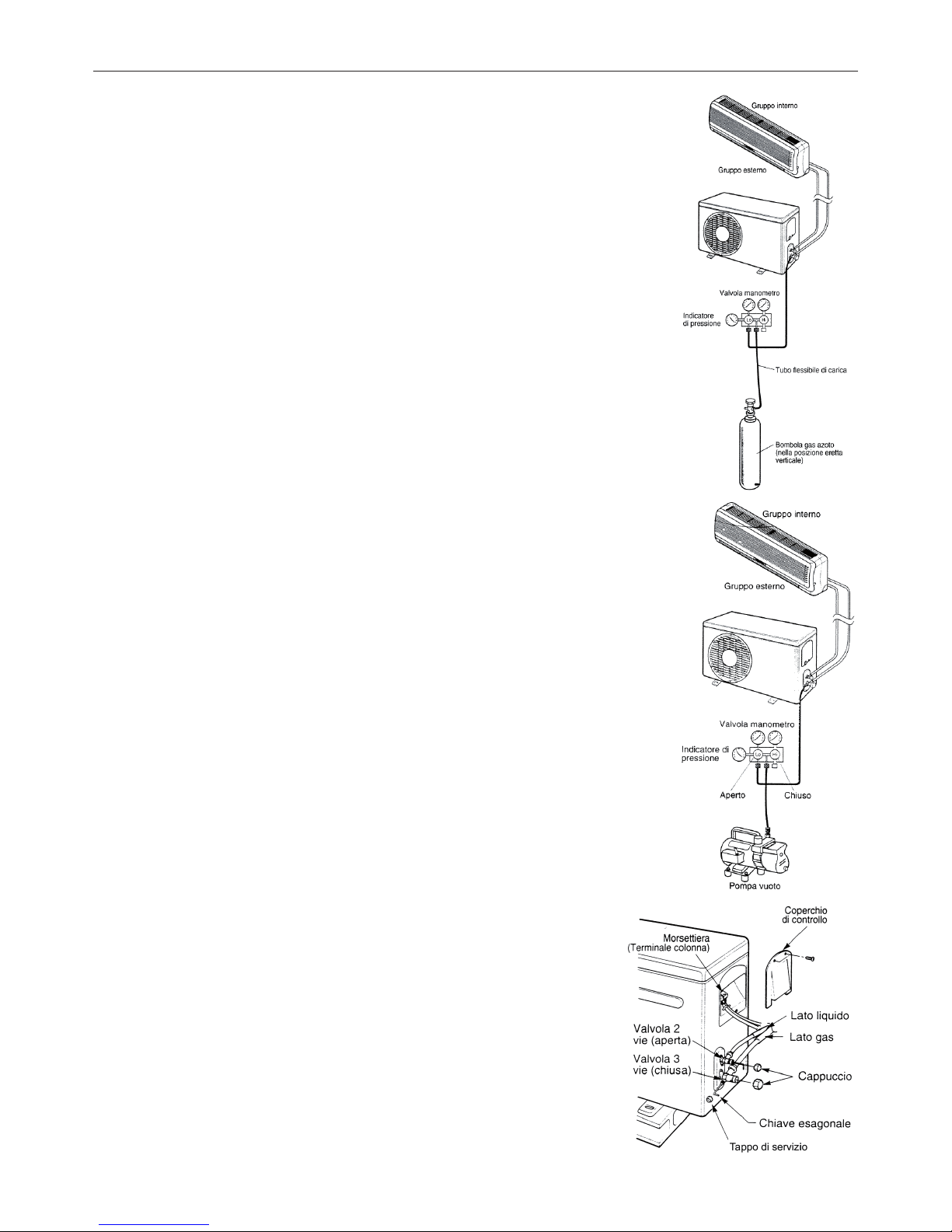
Eliminazione dell'aria con la pompa del vuoto
• Preparazione:
Verificare che ciascun tubo (sia i tubi laterali del gas che del liquido) tra gruppo interno e
gruppo esterno siano stati collegati nel modo corretto e che tutti i cablaggi necessari al
collaudo siano stati effettuati. Rimuovere i cappucci delle valvole di servizio sia dai lati
gas che liquido sul gruppo esterno. Prendere nota del fatto che a questo punto entrambi
le valvole del gas e del liquido rimangono chiuse.
• Lunghezza del tubo e relativa quantità di refrigerante, per una corretta carica verifica
re il valore di surriscaldamento. I valori della tabella sono indicativi.
• Quando si cambia posto all’unità, realizzare lo spurgo con la pompa del vuoto. Assi
curarsi che il refrigerante all’interno del condizionatore sia sempre stato liquido.
Evacuazione
Collegare l’estremità del tubo flessibile di carica alla pompa del vuoto per evacuare le
tubature dell’unità interna. Verificare che la manopola “LO” della valvola del manometro
sia aperta. Poi far funzionare la pompa del vuoto. Il tempo di funzionamento varia a
seconda della lunghezza dei tubi e della capacità della pompa. Quando viene raggiunto
il vuoto desiderato, chiudere la manopola “LO” della valvola del manometro e fermare la
pompa del vuoto.
In conclusione, usando una chiave per valvole di servizio, ruotare lo stelo della valvola
del lato del liquido in senso antiorario per aprirla completamente. Ruotare lo stelo della
valvola del lato gas in senso antiorario per aprirla completamente.
Allentare il tubo flessibile di carica collegato alla presa di servizio del lato gas per scaricare la pressione, poi rimuovere il tubo. Rimettere il dado di copertura della valvola gas
e della presa di servizio e stringere bene con una chiave regolabile. Questa procedura
è molto importante per evitare perdite dall’impianto. Rimettere i cappucci delle valvole
di servizio sia dal lato gas che da quello liquido e stringere bene. Questo completa la
procedura di spurgo dell’aria con la pompa del vuoto, assicurarsi quindi che tutti i tubi
siano collegati in maniera corretta e che le valvole di servizio dei lati gas e liquido siano
completamente aperte.
Svuotamento
Questa procedura viene effettuata quando il gruppo deve essere spostato o viene effettuata l’assistenza al circuito refrigerante.
Svuotamento significa raccogliere tutto il refrigerante nel gruppo esterno senza che si
verifichino perdite.
Attenzione
Assicurarsi di eseguire la procedura di svuotamento con il gruppo in modalità Freddo.
Procedura di recupero
• Collegare un manometro di bassa pressione con un tubo alla presa di servizio della
valvola gas.
• Aprire a metà la valvola gas e svuotare l’aria dalla tubazione del manometro usando
il gas refrigerante.
• Chiudere completamente la valvola liquido.
• Accendere la macchina in modalità raffreddamento.
• Quando la pressione del manometro si porta tra 1 e 0,5 kg/cm 2G (tra 14,2 e 7,1
P.S.G.I.) chiudere completamente la valvola gas e spegnere velocemente il climatiz
zatore. Si è così effettuato il recupero completo del refrigerante dell’unità esterna.

20
ENGLISH

21
INDEX
1. Important informations . . . . . . . . . . . . . . . . . . . . . . . . . . . . . . . . . . . . . . . . . . . . . . . . . . . . . 22
2. Components . . . . . . . . . . . . . . . . . . . . . . . . . . . . . . . . . . . . . . . . . . . . . . . . . . . . . . . . . . . . 23
3. Display . . . . . . . . . . . . . . . . . . . . . . . . . . . . . . . . . . . . . . . . . . . . . . . . . . . . . . . . . . . . . . . . . 23
4. Remote controller . . . . . . . . . . . . . . . . . . . . . . . . . . . . . . . . . . . . . . . . . . . . . . . . . . . . . . . . 24
5. Maintenance . . . . . . . . . . . . . . . . . . . . . . . . . . . . . . . . . . . . . . . . . . . . . . . . . . . . . . . . . . . . 28
6. Operations and performances . . . . . . . . . . . . . . . . . . . . . . . . . . . . . . . . . . . . . . . . . . . . . . . 29
7. Problems and causes . . . . . . . . . . . . . . . . . . . . . . . . . . . . . . . . . . . . . . . . . . . . . . . . . . . . . 30
8. Installation . . . . . . . . . . . . . . . . . . . . . . . . . . . . . . . . . . . . . . . . . . . . . . . . . . . . . . . . . . . . . . 31
22
Do not perform operations that involve opening the appliance.
Electrocution from live components. Personal injury from
burns due to overheated components orwounds caused by
sharp edges or protrusions.
Do not perform operations that involve removing the appliance from its place of installation.
Electrocution from live components. Personal injury from burns due to cooling gases leaking from disconnected piping.
Do not start or stop the appliance by simply plugging it
into or out of the electricity mains.
Electrocution from a damaged cable or plug or socket.
Do not damage the power supply cable. Electrocution from live unsheathed wires.
Do not leave anything on top of the appliance. Personal injury from an object falling off the appliance fol-
lowing vibrations.
Do not climb onto the appliance. Personal injury due to the appliance falling.
Do not climb onto chairs, stools, ladders orunstable supports to clean the appliance.
Personal injury from falling from a height or from cuts (stepladders shutting accidentally).
Do not attempt to clean the appliance without rst turning
it off and unplugging it or switching the dedicated switch
off.
Electrocution from live components.
Do not allow children or inexperienced people to use the
appliance.
Damage to the appliance due to improper use.
Do not direct the air ow towards gas hobs orgas stoves.
Explosions, res or intoxication from the discharge of gas
leaking from the burner nozzle once the air ow has put the
ame out.
Do not place your ngers in the air outlets or in the air
inlet grilles.
Electrocution from live components. Personal injury from
cuts.
Do not drink the condensation water. Personal injury from poisoning.
Should the smell of burning be detected or smoke exit
the appliance, disconnect it from the electricity supply,
open all windows and call in the technician.
Personal injury from burns or smoke inhalation.
Do not perform operations that involve removing the appliance from its place of installation.
Flooding due to water leaking from disconnected piping.
Do not leave anything on top of the appliance. Damage to the appliance or any objects underneath it due to
the appliance falling off from its place of instalation.
Do not use any insecticides, solvents or aggressive detergents to clean the appliance.
Damage to the plastic and painted parts.
Do not use the appliance for any use other than normal
domestic use.
Damage to the appliance due to operation overload. Damage
to objects treated inappropriately.
Do not allow children or inexperienced people to use the
appliance.
Damage to the appliance due to improper use.
Do not direct the air ow towards valuable articles, plants
or animals.
Damage or perishing due to excessive cold/heat, humidity,
ventilation.
Do not use the air conditioning unit for extended periods
of time in conditions of more than 80% humidity.
Damage to objects due to excessive dripping of codensation
from the appliance.
NORM: RISK:
1. IMPORTANT INFORMATIONS
23
2. COMPONENTS
INDOOR UNIT
OUTDOOR UNIT
3. DISPLAY
(1) Aifr intake
(2) Front panel
(3) Control panel
(4) Air outlet
(5) Air flow louver
(6) Air filter
(7) Aifr intake
(8) Connecting pipe
(9) Drain
(10) Air outlet
(11) Air intake
(12) Remote controller
(1) LED signal receiver
(2) Operation indicator
This indicator flashes after power is on and illuminates when the unit is in operation.
(3) Heating indicator
This indicator illuminates during the operation in heating mode.
(4) Cooling indicator
This indicator illuminates during the operation in cooling mode.
(5) Setting temperature indicator
It displays the setting temperature during the operation of the air condizioner.
(6) Dehumidification indicator
It illuminates during the operation in dehumidification mode
(1)(2)(3)
(4) (5) (6)
(1)
(4)
(2)
(6)
(5)
(11)
(9)
(3)
(7)
(10)
(1)
(2)
(4)
(5)
(6)
(11)
(12)
(12)
(10)
(8)
(7)
(3)
(9)
(8)
23
8888:
FAN
HOUR
ON-OFF
AUTO
OPER
FAN
CLOCK
TIMER OFF
TIMER ON
LIGHTSLEEPTURBO
ON/OFF MODE
BLOW TEMP
°F
°C
+
-
23
8888:
FAN
HOUR
ON-OFF
AUTO
OPER
FAN
CLOCK
TIMER OFF
TIMER ON
LIGHTSLEEPTURBO
ON/OFF MODE
BLOW TEMP
°F
°C
+
-
24
4. REMOTE CONTROLLER
4. REMOTE CONTROLER
DISPLAY
DESCRIPTION OF FUNCTIONS OF REMOTE CONTROLLER KEYS
1) ON/OFF key to turn the air conditioner on and off.
2)
TEMPERATURE keys to adjust ambient temperature and the timer: "+" increasing, "-" decreasing.
3) FAN key to set the fan speed by the choosing Automatic - low - mid - high:
4) The CLOCK key is used to set the current time
5) BLOW button: active only in COLD and DEHUMIDIFICATION modes.
6) TURBO button to enable/disable the rapid cooling mode.
7) SLEEP overnight button to set/cancel the Sleep mode regardless of the operating mode of
the conditioner.
8) TEMP button: press to show the set point temperature on the unit’s display.
9) LIGHT button: activates or deactivates the unit’s display.
10) TIMER selection button.
11)
button to enable/disable the air louver automatic mode.
12) MODE button to select the operating mode: AUTO - COOL- DRY - FAN - HEAT:
AUTO: the conditioner automatically sets the suitable operating mode (HEAT, DRY, FAN, COOL)
depending on room temperature.
COOL: the unit begins to operate if the set temperature is lower than that of the room.
DRY: for Dehumidify
FAN: the unit get the air automatically circulating in the room.
HEAT: the unit begins to operate if the set temperature is higher than that of the room.
Name and functions of the display indicators.
1) AUTO mode indicator.
2) COOL mode indicator.
3) BLOW mode indicator.
4) DRY mode indicator.
5)
TURBO mode indicator.
6) FAN mode indicator.
7) HEAT mode indicator.
8) CLOCK indicator.
9)
SLEEP mode indicator.
10) TEMP indicator.
11) Air deflector indicator.
12) LIGHT indicator.
13)
LOCK indicator.
14) TIMER ON-OFF mode indicator.
15) Temperature display indicator.
16) Signal sent confirmation LED.
17) Fan Speed indicator: Auto - Low - Mid - High.
AUTO
23
88 88:
FAN
HOUR
ON-OFF
AU TO
OPER
FAN
CLOCK
TIMER OFF
TIMER ON
LIGHTSLEEPTURBO
ON/OFF MODE
BLOW TEMP
°F
°C
+
-
1
2
3
4
5
6
7
8
9
10
11
12
23
88 88:
FAN
HOUR
ON-O F F
°C
AUTO
OP ER
1
2
3
4
5
6
7
8
9
10 11 12
14
13
15
1617
25
How to insert the batteries
Use two new alkaline type batteries with AAA 1,5V.
(1) Slide down the cover of the battery compartment.
Remove the used batteries and insert new ones correctly.
(2) Reattach the cover by sliding it back into its position.
NOTE
- Do not use old batteries or different type batteries. Such a use may cause remote control
wrong functioning.
- If you do not use the remote control more than two weeks, remove the batteries. Damages
may be caused by possible leakages.
- Replace batteries when no "beep" is received from the indoor unit or if the transmission
indicator on the remote controller fails to light.
Notes for Using the Remote Controller
Put the remote controller on the frame. Fix the frame on the wall or pillar with attached
screw (to ensure the normal signal transmission).
How to use
Keep the remote controller where its signals can reach the receiver of the indoor unit.
A distance of 7m is allowed.
Operating modes
(1) Slecting mode
Each TIME MODE button is pressed, the operation mode is changed in sequence:
AUTO ( ) COOL ( ) DRY ( ) FAN ( ) HEAT ( )
(2) Fan mode
Each time the FAN button is pressed, the fan speed is changed in sequence:
Auto
Low ( ) Medium ( ) High ( )
At "FAN ONLY" mode, only "High", "Medium", and "Low" are available. At "DRY" mode,
Fan speed is set at "Low" automatically, "FAN" button is ineffective in this case.
(3) Setting temperature
- Press the button ''+'' once to raise the setting temperature by 1°C.
- Press the button ''-" once to decrease the setting temperature by 1°C.
(4) Turning on
Press the ON/OFF button, when the appliance receives the signal, the OPERATION
indicator of the indoor unit lights up.
Notes:
- Changing modes during operation, sometimes the unit does not response at once
Wait 3 minutes.
- During heating operation, air flow is not discharged at the beginning. After 2 or 5
minutes, the air flow will be discharged until temperature of indoor heat exchanger rises.
- Wait 3 minutes before restarting the appliance.
4. REMOTE CONTROLER
2
1
3
4
23
8
88
8
:
F
AN
HO
U
R
O
N
-
O
F
F
A
U
T
O
O
P
E
R
F
A
N
C
L
O
C
K
T
I
ME
R
OF
F
TI
ME
R
O
N
L
I
G
H
T
S
L
E
E
P
T
U
R
B
O
O
N
/
O
FF
M
O
D
E
B
L
O
W T
E
M
P
°
F
°
C
+
-
23
88
88:
FA
N
HO
UR
ON
-O
FF
AU
TO
OP
ER
FA
N
CLO
CK
TI
MER
OF
F
TI
MER
ON
L
IGH
T
SL
EEP
T
URB
O
ON
/OFF
MO
DE
BLOW
T
EMP
°F
°C
+
-
Range of available set temperature
HEATING, COOLING 16°C - 30°C
DRY Unable to set
FAN ONLY Unable to set
26
4. REMOTE CONTROLER
Air flow direction control
Vertical air flow automatically adjusted to a certain angle in accordance with the operation mode after turning on the unit.
Note : The direction of air flow can be also adjusted by pressing the " " button of the remote controller.
* Vertical air flow control (with the remote controller)
Using remote controller to set various angles of flow or specific angle as you like.
Swing air flow
When the appliance is powered on, the baffle will set at a preset angle.
Press the " " key to regulate the flow of air issued by the interior unit.
Press the key once and the baffle will continue to move, mixing the ambient air.
Press the " " key a second time and the baffle will lock.
Desired direction air flow
Pressing the " " button again when the louvers swing to a suitable angle as desired.
* Horizontal air flow control (with hands)
Turning the control rods of the horizontal adjustment louvers to change horizontal air flow as shown.
Note:
The shape of the unit may look different from that of the air conditioner you have selected.
- Do not turn the vertical adjustment louvers manually, otherwise malfunction may occur. If that happens, turn off the unit first and
cut off the power supply, then restore power supply again.
- It is better not to let the vertical adjustment louver tilt downward for a long time at COOLING or DRY mode to prevent condensed
water from dripping.
AUTO MODE OPERATION
During the AUTO mode, the unit selects automatically HEATING, DRYING, FAN, COOLING as function of the room temperature
Starting AUTO mode:
At first turn on the air conditioner and then select the AUTO operation by mean of the MODE key.
The automatic operating mode selection and temperature are determined by the indoor temperature, according the following table:
Note:
- In feel mode no temperature will be displayed.
- It may happen that no air is expelled from the indoor unit while it is in operation.
- The unit will not always start operating immediately after the mode has been changed.
OPERATING MODE SELECTION
By pressing the "MODE" key it is possible to select the desired operating mode, as follows: AUTO COOL- DRY - FAN - HEAT.
1)
AUTO Mode: this mode could be set by pressing the "MODE" key until the its indicator (1) appears
on the display. The appliance automatically sets the suitable operating mode (HEAT, DRY, FAN, COOL)
depending on room temperature.
2)
COOL Mode: this mode could be set by pressing the "MODE" key until its indicator (2) appears on the
display. The unit starts to operate if the set temperature is lower than that of the room.
3) DRY Mode: this mode could be set by pressing the "MODE" key until its own indicator (3) appears on
the display. The unit will start to operate in the cooling mode decreasing quickly the room temperature till
reaching the set temperature.
Condensation may form on the delivery port if the "DRY" function is used for a long period of time.
4) FAN Mode: this mode is set by pressing the "MODE" key until its own indicator (4) appears on the
display and the unit get the air automatically circulating in the room.
5) HEAT Mode: this mode is set by pressing the "MODE" key until its own indicator (5) appears on the
display. The unit stars to operate if the set temperature is higher than that of the room.
Control rods of horizontal
adjustment louvers
FEEL
M
ODE
1
2
3
4
5
12
30
:
22
FAN
°C
AU
TO
O
PER
FA
N
CLO
CK
TI
MER
OF
F
TI
MER
ON
L
IGH
T
SL
EEP
T
URB
O
ON/OFF
MO
DE
BL
OW
T
EMP
+
-
FA
N
CLO
CK
TI
MER
OF
F
TI
MER
ON
L
IGH
T
SL
EEP
T
URB
O
ON
/OFF
MO
DE
BL
OW
T
EMP
+
-
E
Indoor temperature
Operating mode
Temp. impostata
Less tan 21°C
Heating 18°C
21°C ~ 24°C
Fan only /
More than 26°C
Cooling 25°C
Your feeling
Button
Adjusting procedure
Uncomfortable because of unsuitable
air flow volume.
FAN
Indoor fan speed alternates among High, Medium and Low each time this
button is pressed.
Uncomfortable because of unsuitable
flow direction.
SWING
Press it once, the vertical adjustment louver swings to change vertical airflow
direction. Press it again, swings stops.
For horizontal airflow direction, please refer to the previous page for details.
Operation mode Direction of airflow
COOLING, DRY
Horizontal
* HEATING, FAN ONLY
Downward
27
4. REMOTE CONTROLER
AUT
O/ST
OP
CLOCK SETTING
To adjust the real time press CLOCK button, then use ''+'' and ''-'' buttons to get the correct time.
- Press the key ''+'' / ''-'' once to increase/decrease the time setting by 1 minute.
- Press the key ''+'' / ''-'' for 1.5 seconds to increase/decrease the time setting by 10 minutes.
- Press CLOCK button again the real time is set.
TIMER MODE SETTING
Push the buttons TIMER ON/OFF to set the timer programming as wished in order to switch on an off
the air conditioner at the desired time.
- How to set TIMER ON
TIMER ON button can be used to set the timer programming as wished in order to switch on the
appliance at your desired time.
1) Press TIMER ON button, "ON" flashes on the LCD, then you can press the ''+'' or ''-'' buttons to
select your desired time for appliance on.
- Press the ''+'' / ''-'' button once to increase or decrease the time setting by 1 minute.
- Press the key ''+'' / ''-'' for 1.5 seconds to increase/decrease the time setting by 10 minutes.
Note: If you don't set the time in 10 seconds after you press TIMER ON button, the remote controller
will exit the TIMER ON mode automatically.
2) When your desired time displayed on LCD, press the TIMER ON button and confirm it, a beep can
be heard and then the TIMER indicator "ON" the indoor unit stops flashing.
3) After the set timer displayed, the clock will be displayed on the LCD of the remote controller
instead of set timer.
How to cancel TIMER ON
Press the TIMER ON button again, a "beep" can be heard and the indicator disappears, the TIMER ON mode has been canceled.
Note: It is similar to set TIMER OFF, you can make the appliance switch off automatically at your desired time.
CAUTIONS
When you select the timer operation the remote control automatically transmits the timer signal to the indoor unit at the specified
time.
Therefore keep the remote control in a location from which it can transmit the signal to the indoor unit properly. The effective operation time setted by the remote control is limited in 24 hours.The timer function (ON/OFF) which is the
closest to the actual time will be activated first.
The timer will not work if ON and OFF timer are set at the same time.
SLEEP mode
SLEEP mode can be set in COOLING or HEATING operation mode. This function gives you a more
comfortable environment for sleep.
In SLEEP mode,
- Fan speed is automatically set at low speed.
- Press the "SLEEP" button to set the unit to the sleep mode. The SLEEP indicator will light up on
the display. The temperature increases/decrease in cooling/heating mode operation by 1°C at set
intervals. After reaching 2°C the unit maintains this temperature through to the eighth hour (8 hours)
of operation in the "SLEEP" mode and then switches off automatically.
TURBO mode:
- TURBO mode is used to start or stop fast cooling and heating at high fan speed.
- In Turbo mode, you can set airflow direction or timer. If you want to exit from TURBO mode, press any
- TURBO, MODE, FAN or ON/OFF button, the display will return to the original mode.
BLOW mode:
When the unit is switched off after cooling or dehumidifying operation, the fan will start to ventilate the
coil for 10 minutes in order to prevent any residual condensation from forming mould and bad smells.
LOCK mode:
Press the ''+'' and ''-'' buttons at the same time to block the last setting operation by the remote controller. All the buttons disabled, including the ON/OFF button. Press the ''+'' and ''-'' buttons again to
enable the buttons functions.
°C / °F mode: press the ''MODE'' and ''-'' buttons at the same time with the unit off to choose the
display of temperature in °C and °F.
EMERGENCY BUTTON
It allows turning the unit on/off when the remote controller is missed or broken. Operating mode and
the preset temperature are automatically adjusted depending on the room temperature at switch-on.
AUTO-RESTART FUNCTION
The unit is set to switch on automatically in the case of power failure.
25
12
00
:
FAN
HO
UR
ON
-OFF
°C
AU
TO
O
P E
R
AUT
O/ST
OP
23
88
88:
FA
N
HO
UR
ON
-O
FF
AU
TO
OP
ER
FA
N
CLO
CK
TI
MER
OF
F
TI
MER
ON
L
IGH
T
SLEEP
T
URB
O
ON
/OFF
MO
DE
BL
OW
T
EMP
°F
°C
+
-
FA
N
CLO
CK
TI
MER
OF
F
TIMER
ON
L
IGH
T
SLEEPT
URBO
ON/OFF
MO
DE
BLOW
T
EMP
+
-
F
FA
N
CLO
CK
TI
MER
OF
F
TIMER
ON
L
IGH
T
SLEEPT
URBO
ON/OFF
MO
DE
BL
OW
T
EMP
+
-
E
E
ON -OF
F
00
3 :
O
N -OF
F
23
C
28
5. MAINTENANCE
It is necessary to stop the air conditioner and disconnect the power supply before
cleaning.
Cleaning the indoor unit and remote controller
- Use a dry cloth to wipe the indoor unit and remote controller.
- A cloth dampened with cold water may be used on the indoor unit if it is very
dirty.
- The front panel of the indoor unit can be removed and cleaned with water. Then
wipe it with a dry cloth.
- Do not use a chemically treated cloth or duster to clean the unit.
- Do not use benzine, thinner, polishingh powder, or similar solvents for cleaning.
These may caus the plastic surface to crack or deform.
Cleaning the air filter
A clogged air filter reduces the cooling efficiency of this unit. Please clean the
filter once every 2 weeks.
1. Lift the indoor unit panel up to an angle until it stops with a clicking sound.
2. Take hold of the handle of the air filter and lift it up slightly to take it out from
the filter holder, then pull it downwards.
3. Remove the AIR FILTER from the indoor unit.
- Clean the AIR FILTER once two weeks.
- Clean theAIR FILTER with a vacuum cleaner or water, then dry it up cool place.
4. Remove the Electrostatic Filter from its support frame as shown in the Figure
on the left (Not applicable to the units without electrostatic filter).
Do not touch this Electrostatic Filter within 10 minutes after opening the inlet gril
-
le, it may cause an electric shock.
- Clean the electrostatic filter with mild detergent or water and dry in the sunlight
for two hours.
- Before re-install the Electrostatic Filter, check whether the corona line or support frame is damaged or not.
5. Install the air freshening filter back into position.
6. Insert the upper portion of air filter back into the unit taking care that the left
and right edges line up correctly and place filter into position.
Maintenance
If you plan to idle the unit for a long time, perform the following:
(1) Operate the fan for about half a day to dry the inside of the unit.
(2) Stop the air conditioner and disconnect power. Remove the batteries from the
remote controller.
(3) The outdoor unit requires periodic maintenance and cleaning. Do not attempt
to do this yourself. Contact your dealer or servicer.
Checks before operation
- Check that the wiring is not broken off or disconnected.
- Check that the air filter is installed.
- Check if the air outlet or inlet is blocked after the air conditioner has not been
used for a long time.
- Do not touch the metal parts of the unit when removing the filter. Injuries can
occur when handling sharp metal edges.
- Do not use water to clean inside the air conditioner. Exposure to water can
destroy the insulation, leading to possible electric shock.
- When cleaning the unit, first make sure that the power and circuit breaker are
turned off.
WARNING
CAUTIONS
CAUTIONS

29
6. OPERATIONS AND PERFORMANCES
The following events may occur during normal operation.
1. Protection of the air conditioner.
Compressor protection
- The compressor can't restart for 3 minutes after it stops.
Anti-cold air (Cooling and heating models only)
- The unit is designed not to blow cold air on HEAT mode, when the indoor heat exchanger is in one of the following three situations and the set temperature has not been reached.
A) When heating has just starting.
B) Defrosting.
C) Low temperature heating.
- The indoor or outdoor fan stop running when defrosting (Cooling and heating models only). Defrosting (Cooling and heating
models only)
- Frost may be generated on the outdoor unit during heat cycle when outdoor temperature is low and humidity is high resulting in
lower heating efficiency of the air conditioner.
- During this condition air conditioner will stop heating operation and start defrosting automatically.
- The time to defrost may vary from 4 to 10 minutes according to the outdoor temperature and the amount of frost buildup on the
outdoor unit.
2. A white mist coming out from the indoor unit
- A white mist may generate due to a large temperature difference between air inlet and air outlet on COOL mode in an indoor environment that has a high relative humidity.
- A white mist may generate due to moisture generated from defrosting process when the air conditioner restarts in HEAT mode
operation after defrosting.
3. Low noise of the air conditioner
- You may hear a low hissing sound when the compressor is running or has just stopped running. This sound is the sound of the
refrigerant flowing or coming to a stop.
- You can also hear a low "squeak" sound when the compressor is running or has just stopped running. This is caused by heat
expansion and cold contraction of the plastic parts in the unit when the temperature is changing.
- A noise may be heard due to louver restoring to its original position when power is first turned on.
4. Dust is blown out from the indoor unit.
This is a normal condition when the air conditioner has not been used for a long time or during first use of the unit.
5. A peculiar smell comes out from the indoor unit.
This is caused by the indoor unit giving off smells permeated from building material, from furniture, or smoke.
6. The air conditioner turns to FAN only mode from COOL or HEAT (For cooling and heating models only) mode.
When indoor temperature reaches the temperature setting on air conditioner, the compressor will stop automatically, and the air
conditioner turns to FAN only mode. The compressor will start again when the indoor temperature rises on COOL mode or falls on
HEAT mode (For cooling and heating models only) to the set point.
7. Dripping water may generate on the surface of the indoor unit when cooling in a high relatively humidity (relative humidity higher
than 80%). Adjust the horizontal louver to the maximum air outlet position and select HIGH fan speed.
8. Heating mode (For cooling and heating models only)
The air conditioner draws in heat from the outdoor unit and releases it via the indoor unit during heating operation. When the
outdoor temperature falls, heat drawn in by the air conditioner decreases accordingly. At the same time, heat loading of the air conditioner increases due to larger difference between indoor and outdoor temperature. If a comfortable temperature can't be achieved
by the air conditioner, we suggest you use a supplementary heating device.
9. Auto-restart function
Power failure during operation will stop the unit completely.
For the unit without Auto-restart feature, when the power restores, the OPERATION indicator on the indoor unit starts flashing. To
restart the operation, push the ON/OFF button on the remote controller. For the unit with Auto-restart feature, when the power
restores, the unit restarts automatically with all the previous settings preserved by the memory function.
10. Lightning or a car wireless telephone operating nearby may cause the unit to malfunction.
Disconnect the unit with power and then re-connect the unit with power again. Push the ON/OFF button on the remote controller to
restart operation.
OPERATIONS AND PERFORMANCES
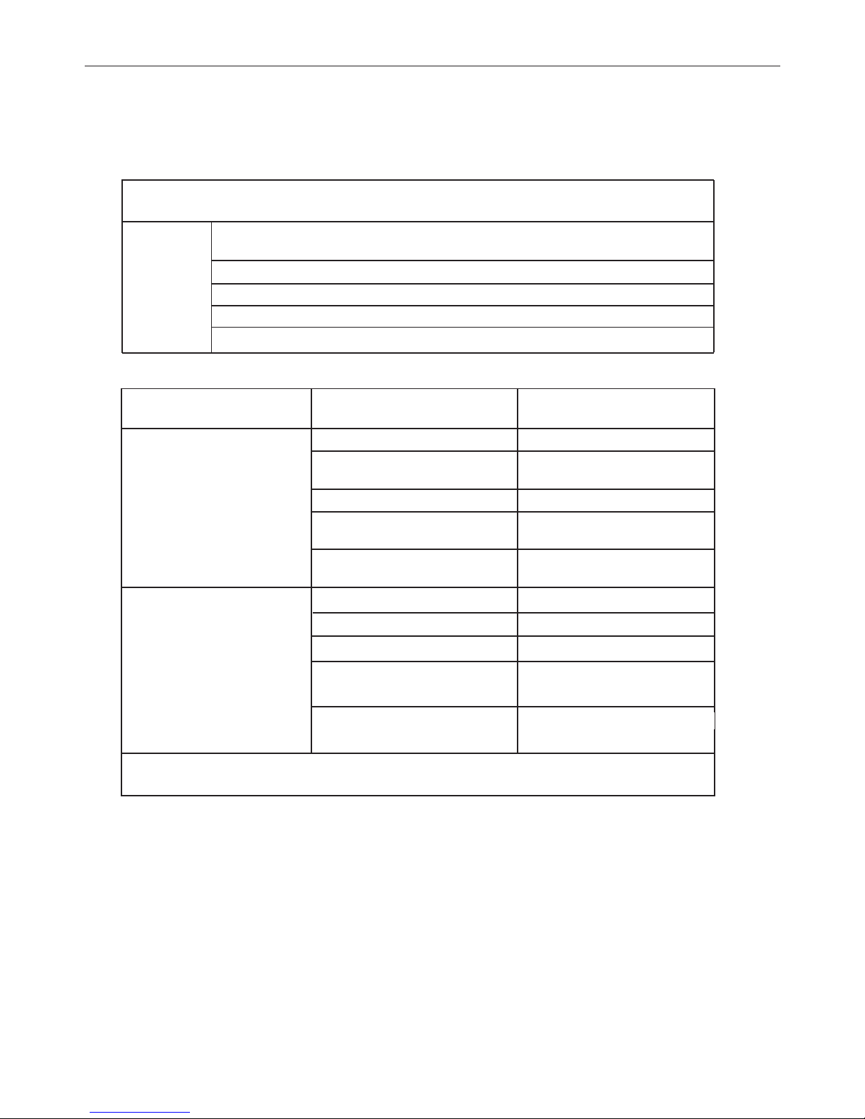
30
7. TROUBLES AND CAUSES
TROUBLES AND CAUSES
Stop the air conditioner immediately if one of the following faults occur. Disconnect the power and contact
the nearest custmer service center.
OPERATION indicator or other indicators flash rapidly (5 times every second) and this flash
cannot be fixed by disconnecting the power, and then connect it again
Fuse blows frequently or circuit breaker trips frequently
Other objects or water penetrate the air conditioner
The remote controller won’t work or works abnormally
Other abnormal situations
Trouble
Malfunctions
Cause
What should be done?
Unit does not start
Powe cut Wait for power to be restored
Unit may have become unplugged.
Check that plug is securely in wall
receptable
Fuse may have blown.
Replace the fuse
Battery in remote controller may
have been exhausted.
Replace the battery
The time you have set with timer is
incorrect.
Wait or cancel timer setting
Unit not cooling or heating (Cooling/heating models only) room
very well while air flowing out from
theair conditioner
Inappropriate temperature setting
set temperature correctly
Air filter is blocked
Clean the air filter
Air inlet or outlet of indoor or
outdoor unit has been blocked
Doors or Windows are open Close the doors or windows
Clear obstructions away first, then
restart the unit
Compressor 3 minutes protection
has been achieved
Wait
If the trouble has not been corrected, please contact a local dealer or the nearest custmer service center. Be
sure to inform them of the detailed malfunctions and unit model.
Notes:
- Do not attempt to repair the unit yourself.
- Always consult an authorised service provider.

31
8. INSTALLATION
Indoor unit
•Do not expose the indoor unit to heat or steam.
•Select a place where there are no obstacles in front or around the unit.
•Make sure that condensation drainage can be conveniently routed away.
•Do not install near a doorway.
•Ensure that the space on the left and right of the unit is more than 12cm.
•Use a stud nder to locate studs to prevent unnecessary damage to the wall.
•A minimum pipe run of 3 metres is required to minimise vibration & excessive noise.
•The indoor unit should be installed on the wall at a height of 2.3 metres or more from the oor.
•The indoor unit should be installed allowing a minimum clearance of 15cm
from the ceiling.
•Any variations in pipe length will/may require adjustment to refrigerant charge.
Outdoor unit
If an awning is built over the outdoor unit to prevent direct sunlight or rain exposure, make sure that heat radiation from the condenser is not restricted.
•Ensure that the clearance around the back of the unit is more than 30cm and left side is more than 30cm. The front of the unit should
have more than 200cm of clearance and the connection side (right side) should have more than 60cm of clearance.
Do not place animals and plants in the path of the air inlet or outlet.
•Take the air conditioner weight into account and select a place where noise and vibratiol will not be an issue.
•Select a place so that the warm air and noise from the air conditioner do not disturb neighbours.
•Install the outdoor unit on a rigid base to prevent increasing noise level and vibration.
•Determine the air outlet direction where the discharged air is not blocked.
•In the case that the installation place is exposed to strong wind such as a seaside, make sure the fan operating properly by putting
the unit lengthwise along the wall or using a dust or shield plates.
•Specially in windy area, install the unit to prevent the admission of wind.
•If need suspending installation, the installation bracket should accord with technique requirement in the installation bracket diagram.
The installation wall should be solid brick, concrete or the same intensity construction, or actions to reinforce, damping supporting
should be taken. The connection between bracket and wall, bracket and the air conditioner should be rm, stable and reliable.
•Be sure there is no obstacles which block radiating air.
Rooftop installation:
•If the outdoor unit is installed on a roof structure, be sure to level the unit. Ensure the rocstructure and anchoring method are adequate for the unit location.
•Consult local codes regarding rooftop mounting.
•If the outdoor unit is installed on roof structures or external walls, this may result in excessive noise and vibration, and may also be
classed as a non serviceable installation.
YES
YES
NO
2
≤
250 cm
0
2 0
≤ 60 cm
≤ 50 cm
≤
15 cm
≤ 15 cm
≤ 15 cm
≤15 cm
≤15 cm
≤ 60 cm

32
8. INSTALLATION
Fit the installation Plate
1. Fit the installation plate horizontally on structural parts of the wall with spaces around the installation plate.
2. If the wall is made of brick, concrete or the like, drill eight (8) 5mm diameter holes in the wall. Insert Clip anchor for appropriate
mounting screws.
3. Fit the installation plate on the wall with eight (8) type "A" screws.Fit the Installation Plate and drill holes in the wall according
to the wall structure and corresponding mounting points on the installation plate. (Dimensions are in "mm" unless otherwise sta
ted).
Drill a hole in the wall
1. Determine hole positions according to the diagram detailed in Fig.5. Drill one (1) hole (65mm) slanting slightly to outdoor side
2. Always use wall hole conduit when drilling metal metal plate or the like.
Connective Pipe and Drainage Installation
1. Run the drain hose sloping downward. Do not install the drain hose as illustrated below.
2. When connecting extension drain hose, insulate the connecting part of extension
drain hose with a shield pipe, do not let the drain hose slack.
Connective pipe
1. For the left-hand and right-hand piping, remove the pipe cover from the side panel.
• Explain to clients that the pipe cover must be kept as it may be used when relocate the air conditioner to any other place.
2. For the rear-right-hand and rear-left-hand piping, install the piping as shown. Bend the connective pipe to be laid at 43mm hei
ght or less from the wall.
3. Fix the end of the connective pipe. (Refer to Tightening Connection in REFRIGERANT PIPING CONNECTION).
Indoor unit installation
1. Pass the piping through the hole in the wall.
2. Put the upper claw at the back of the indoor unit on the upper hook of the installation plate, move the indoor unit from side to
side to see that it is securely hooked.
3. Piping can easily be made by lifting the indoor unit with a cushioning
material between the indoor unit and the wall. Get it out after piping.
4. Push the lower part of the indoor unit up on the wall. Then move the
indoor unit from side to side, up and down to check if it is hooked secu
rely.
Settlement of outdoor unit
Anchor the outdoor unit with a bolt and nut 10 or 8 tightly and horizontally
on a concrete or rigid mount.
Drain joint installation
Fit the seal into the drain elbow, then insert the drain joint into the base pan hole of outdoor unit, rotate 90 to securely assemble
them. Connecting the drain joint with an extension drain hose (Locally purchased), in case of the water draining off the outdoor unit
during the heating mode.
Piping and wrapping
Bundle the tubing, connecting cable,anddrain hose with tape securely.
• Because the condensed water from rear of the indoor unit is gathered in ponding box and is
piped out of room. Do not put anything else in the box.
CAUTION
• Connect the indoor unit first, then the outdoor unit.
• Do not allow the piping to let out from the back of the indoor unit.
• Be careful not to let the drain hose slack.
• Heat insulated both of the auxiliary piping.
• Be sure that the drain hose is located at the lowest side of the bundle. Locating at the
upper side can cause drain pan to over flow inside the unit.
• Never intercross nor intertwist the power wire with any other wiring.
• Run the drain hose sloped downward to drain out the condensed water smoothly.
Indoor unit
Drain hose
Wrapping
belt
Connective
pipe
Ponding box
Connective
cable
Capacity (W)
Connective pipe length
max (m)
Connective pipe length
L(m)
Difference in level
H (m)
Additional amount of refrigerant to be
charge (g/m) , se L(m) > 5 m
2600 W ~ 5300 W
5 15 10 20
7000 W 5 25 10 50

33
Wiring connections
Connect the cable to the indoor unit
1. Indoor/Outdoor connection cable should be suitable.
2. Lift the indoor unit panel up and remove the screw, then remove the window cover.
3. Connect cables according to their marks to terminals.
4. Wrap those cables not connected with terminals with insulation tapes, so that they will not touch
any electrical components.
Connect the cable to the outdoor unit
1. Remove the electric parts cover from the outdoor unit.
2. Connect the connective cables to the terminals as identified with their respective matched num
bers on the terminal block of indoor and outdoor units.
3. To prevent the ingress of water, from a loop of the connective cable as illustrated in the installation
diagram of indoor and outdoor units.
4. Insulate unused cords (conductors) with PVC-tape. Process them so they do not touch any electri
cal or metal parts.
Wires specifications
8. INSTALLATION
INDOOR UNIT
OUTDOOR UNIT
Front panel Terminal
Acces door
terminal
ON/OFF MONO
Capacity (W)
Power connecting cable Indoor - outdoor connecting cable Main power
supply
Section Section
2600 W, 3500 W 1,5 mm² x 3 1,5 mm² x 5
To indoor unit
5300 W 2,5 mm² x 3 2,5 mm² x 3 + 1,5 mm² x 2 To indoor unit
7000 W 2,5 mm² x 3 2,5mm² x 3 + 1,5 mm² x 3 To indoor unit
YEGN
YEGN
BU BK VT OG
BU BK VT OG
N(1) 2 4 5
N(1)
2 4 5
YEGN
YEGN
BU BK BN VT
OG
BU BK BN VT
OG
N(1) 2 3 4 5
N(1) 2 3 4 5
BU BK BN VT OG
BU BK BN VT OG
YEGN
YEGN
YEGN
N(1) 2 3 4 5
A UNIT: B UNIT:
N(1)
2 3 4
5
L
N
BU BK BN VT OG
N(1)
2 3 4
5
BU BK BN VT OG
YEGN
N(1) 2 3 4 5
N(1)
2 3
N(1)
2 3
BU
BK BN
BNBKBU
YEGN
YEGN
ON/OFF MONO: 2600 W, 3500 W, 5300 W ON/OFF DUAL: (2 X 2600 W), (2600 W + 3500 W), (2 X 3500 W)
ON/OFF DUAL
Capacity (W)
Power connecting cable Indoor - outdoor connecting cable Main power
supply
Section Section
2600 W, 3500 W 1,5 mm² x 3 1,5 mm² x 6
To outdoor unit
DC INVERTER MONO
Capacity (W)
Power connecting cable Indoor - outdoor connecting cable Main power
supply
Section Section
2600 W 1,5 mm² x 3 1,5 mm² x 4
To indoor unit
3500 W ~ 7000 W 2,5 mm² x 3 2,5 mm² x 4 To indoor unit
ON/OFF MONO: 7000 W DC INVERTER MONO: 2600 W, 3500 W, 5300 W, 7000 W

34
8. INSTALLATION
Refrigerant piping connection
1. Flaring work
Main cause for refrigerant leakage is due to defect in the flaring work. Carry out correct flaring work using the following procedure:
A: Cut the pipes and the cable.
1. Use the piping kit accessory or pipes purchased locally.
2. Measure the distance between the indoor and the outdoor unit.
3. Cut the pipes a little longer than the measured distance.
4. Cut the cable 1.5m longer than the pipe length.
B: Burr removal
1. Completely remove all burrs from the cut cross section of pipe/tube
2. Put the end of the copper tube/pipe in a downward direction as you remove
burrs in order to avoid dropping burrs into the tubing.
C: Putting nut on
Remove flare nuts attached to indoor and outdoor unit, then put them on pipe/tube
having completed burr removal. (Not possible to put them on after flaring work).
D: Flaring work
Firmly hold copper pipe in a die in the dimension shown in the table below:
Diam. E (mm) A(mm)
Max. Min
Φ6,35 1,3 0,7
Φ9,35 1,6 1
Φ12,7 1,8 1
Φ16 2 1
Tightening Connection
• Align the center of the pipes.
• Sufficiently tighten the flare nut with fingers, and then tighten it with a spanner
and torque wrench as shown.
CAUTION
• Excessive torque can break nut depending on installation conditions.
Hex nut diam. Tightening torque (N.m)
Φ 6 15 ~ 20
Φ 9,52 31 ~ 35
Φ 12 50 ~ 55
Φ 16 60 ~ 65
Φ 19 70 ~ 75

35
8. INSTALLATION
Indoor unit
Outdoor unit
Manifold gauge
Pressure gauge
Charge hose
Nitrogen gas cylinder
(in vertical position)
Air purging
Air and moisture in the refrigerant system have undesirable effects as indicated
below:
• Pressure in the system rises.
• Operating current rises.
• Cooling or heating efficiency drops.
• Moisture in the refrigerant circuit may freeze and block capillary tubing.
• Water may lead to corrosion of parts in the refrigeration system.
Therefore, the indoor unit and tubing between the indoor and outdoor unit must be
leak tested and evacuated to remove any noncondensables and moisture from the
system.
Air purging with vacuum pump
• Preparation
Check that each tube (both liquid and gas side tubes) between the indoor and
outdoor units have been properly connected and all wiring for the test run has
been completed. Remove the service valve caps from both the gas and the liquid
side on the outdoor unit.
Note that both the liquid and the gas side service valves on the outdoor unit are
kept closed at this stage.
• Pipe length and refrigerant amount:
• When relocate the unit to another place, perform evacuation using vacuum
pump.
Make sure the refrigerant added into the air conditioner is liquid form in any case.
Caution in handling the packed valve
• Open the valve stem until it hits against the stopper. Do not try to open it further.
• Securely tighten the valve stem cap with aspanner or the like.
• Valve stem cap tightening torque (See Tightening torque table in previous page).
When Using the Vacuum Pump
(For method of using a manifold valve, refer to its operation manual.)
1. Completely tighten the flare nuts, A, B, C, D, connect the manifold valve charge
hose to a charge port of the low-pressure valve on the gas pipe side.
2. Connect the charge hose connection to the vacuum pump.
3. Fully open the handle Lo of the manifold valve.
4. Operate the vacuum pump to evacuate. After starting evacuation, slightly loose
the flare nut of the Lo valve on the gas pipe side and check that the air is ente
ring (Operation noise of the vacuum pump changes and a compound meter indi
cates 0 instead of minus)
5. After the evacuation is complete, fully close the handle Lo of the manifold valve
and stop the operation of the vacuum pump.
Make evacuation for 15 minutes or more and check that the compound meter
indicates -76cmHg(-1x10⁵Pa).
6. Turn the stem of the packed valve B about 45°counterclockwise for 6-7 seconds
after the gas coming out, then tighten the flare nut again. Make sure the pressu
re display in the pressure indicator is a little higher than the atmosphere
pressure.
7. Remove the charge hose from the Low pressure charge hose.
8. Fully open the packed valve stems B and A.
9. Securely tighten the cap of the packed valve.
Indoor unit
Outdoor unit
Pressure gauge
Manifold gauge
Open
Close
Vacuum pump

36
ESPAÑOL

37
INDICE
1. Informaciones importantes . . . . . . . . . . . . . . . . . . . . . . . . . . . . . . . . . . . . . . . . . . . . . . . . . . . . . . . . . .38
2. Componentes . . . . . . . . . . . . . . . . . . . . . . . . . . . . . . . . . . . . . . . . . . . . . . . . . . . . . . . . . . . . . . . . . . . . 39
3. Display . . . . . . . . . . . . . . . . . . . . . . . . . . . . . . . . . . . . . . . . . . . . . . . . . . . . . . . . . . . . . . . . . . . . . . . . . .39
4. Mando a distancia . . . . . . . . . . . . . . . . . . . . . . . . . . . . . . . . . . . . . . . . . . . . . . . . . . . . . . . . . . . . . . . . .40
5. Mantenimiento . . . . . . . . . . . . . . . . . . . . . . . . . . . . . . . . . . . . . . . . . . . . . . . . . . . . . . . . . . . . . . . . . . . .44
6. Operaciones y servicios . . . . . . . . . . . . . . . . . . . . . . . . . . . . . . . . . . . . . . . . . . . . . . . . . . . . . . . . . . . .45
7. Problemas y sus causas . . . . . . . . . . . . . . . . . . . . . . . . . . . . . . . . . . . . . . . . . . . . . . . . . . . . . . . . . . . .46
8. Instalaciòn . . . . . . . . . . . . . . . . . . . . . . . . . . . . . . . . . . . . . . . . . . . . . . . . . . . . . . . . . . . . . . . . . . . . . . .47
38
1.INFORMACIONES IMPORTANTES
No realice operaciones que impliquen la apertura del
aparato
Fulguración por la presencia de componentes bajo tensión.
Lesiones personales como quemaduras debido a la presencia de componentes recalentados o heridas producidas porbordes y protuberancias cortantes.
No realice operaciones que impliquen laremoción del
aparato del lugar donde estáinstalado
Fulguración por la presencia de componentes bajo tensión.
Lesiones personales como quemaduras por enfriamientodebido al escape de gas de los tubos desconectados.
No ponga en funcionamiento o apague elaparato conectándolo o desconectándolo dela alimentación eléctrica
Fulguración por daño del cable, del enchufe, o del toma
No dañe el cable de alimentación eléctrica Fulguración por la presencia de cables pelados bajo tensión
No deje objetos sobre el aparato Lesiones personales por la caída del objeto como conse-
cuencia de las vibraciones
No suba sobre el aparato Lesiones personales por una caída desde el aparato
No suba a sillas, taburetes, escaleras osoportes inestables para efectuar la limpiezadel aparato.
Lesiones personales por la caída desde lo alto o por
cortes(escaleras dobles)
Antes de realizar operaciones de limpieza delaparato,
apáguelo y desenchúfelo o desconecte el interruptor
correspondiente
Fulguración por la presencia de componentes bajo tensión
No permita que los niños o personas inexper-tas utilicen
el aparato
Daño del aparato por uso impropio
No dirija el ujo de aire hacia encimeras oestufas a gas Explosiones, incendios o intoxicaciones producidas por esca-
pe de gas de los picos de alimentación con llamas apagada-
spor el ujo de aire
No introduzca los dedos en las bocas de salidade aire ni
en las rejillas de aspiración de aire
Fulguración por la presencia de componentes bajo tensión.
Lesiones personales como cortes
No beba el agua de condensación Lesiones personales como intoxicación
En el caso en que se advierta olor a quema-do o se vea
salir humo del aparato, desco-necte el aparato, abra las
ventanas y llame altécnico
Lesiones personales provocadas por quemaduras o inhalación de humo
No realice operaciones que impliquen laremoción del
aparato del lugar donde estáinstalado
Inundaciones por pérdida de agua de los tubos desconectados
No deje objetos sobre el aparato Daño del aparato o de los objetos que se encuentren de-
bajode él, por la caída del aparato como consecuencia de
undesenganche de la jación
No utilice insecticidas, solventes o detergen-tes agresivos para la limpieza del aparato
Daño de las partes de material plástico o pintadas
No utilice el aparato con nalidades diferentesa las de un
uso doméstico normal
Daño del aparato por sobrecarga de funcionamiento.Daño de
los objetos indebidamente tratados.
No permita que los niños o personas inexper-tas utilicen
el aparato
Daño del aparato por uso impropio
No dirija el ujo de aire hacia objetos de valor,plantas o
animales
Daño o deterioro por excesivo frío/calor, humedad o ventilación.
No use el acondicionador por mucho tiempoen condiciones de humedad superior al 80%
Daño de objetos por el goteo debido a una excesiva condensación en el aparato.
NORMA : RIESGOS :

39
2. COMPONENTES
Unidad interior
Unidad exterior
3. DISPLAY
(1) Entrada de aire
(2) Panel delantero
(3) Control manual
(4) Salida de aire
(5) Deflector de aire
(6) Filtro de aire
(7) Entrada de aire
(8) Tubos de conexión
(9) Tubos desagüe
(10) Salida de aire
(11) Entrada de aire
(12) Mando a distacia
(1) LED Señal receptor
(2) Operation indicator
Este piloto parpadea después de conectar la alimentación y se enciende cuando la unidad está funcionando.
(3) Heating indicator
Este indicador ilumina durante la operación en modo calefacción.
(4) Cooling indicator
Este indicador ilumina durante la operación en modo refrigeración.
(5) Setting temperature indicatore
Indica la temperatura elegida cuando está funcionando el acondicionador.
(6) Indicatore di deumidificazione
Este indicador ilumina durante la operación en modo deshumidificación.
(1)(2)(3)
(4) (5) (6)
(1)
(4)
(2)
(6)
(5)
(11)
(9)
(3)
(7)
(10)
(1)
(2)
(4)
(5)
(6)
(11)
(12)
(12)
(10)
(8)
(7)
(3)
(9)
(8)
23
8888:
FAN
HOUR
ON-OFF
AUTO
OPER
FAN
CLOCK
TIMER OFF
TIMER ON
LIGHTSLEEPTURBO
ON/OFF MODE
BLOW TEMP
°F
°C
+
-
23
8888:
FAN
HOUR
ON-OFF
AUTO
OPER
FAN
CLOCK
TIMER OFF
TIMER ON
LIGHTSLEEPTURBO
ON/OFF MODE
BLOW TEMP
°F
°C
+
-
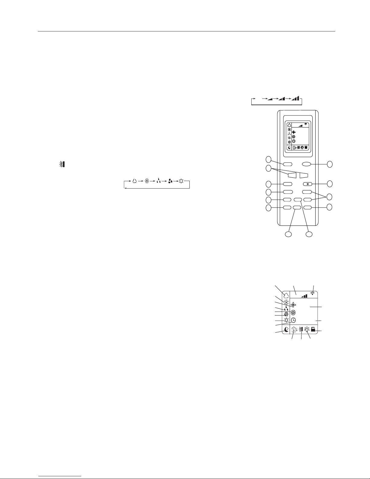
40
4. MANDO A DISTACIA
4. MANDO A DISTACIA
AUTO
DISPLAY
DESCRIZIONE FUNZIONI DEI TASTI DEL TELECOMANDO
El mando a distancia está compuesto por una serie de teclas y un visualizador que muestra todas las funciones activas y los diver
sos parámetros que necesita el usuario para una correcta utilización de la unidad misma.
1) Tecla ON/OFF, enciende y apaga el acondicionador
2) Tecla para imposición de
TEMPERATURA, consigue regular la temperatura ambiente de la estancia "+" pulsándola aumenta
"-" pulsándola disminuye.
3) Tecla FAN permite seleccionar la velocidad del ventilador: automático - bajo - medio - alto.
4) La tecla CLOCK permite programar el horario actual.
5) Botón BLOW activo sólo en modalidades de funcionamiento FRÍO y DESHUMIDIFICACIÓN.
6) Tecla TURBO, activa/desactiva la modalidad de refrigeración rápida.
7) Pulsando la tecla SLEEP, usada para seleccionar/cancelar la función Sleep,
independientemente del modo en el que esté funcionando el acondicionador.
8) Botón TEMP permite visualizar en el monitor de la unidad la temperatura de set point y
ambiente.
9) Botón LIGHT activa/desactiva el monitor de la unidad.
10)Tecla de selección TIMER
11) Tecla para activar/desactivar el movimiento automático del deflector de aire.
12) Pulsando MODE, permite seleccionar el modo de funcionamiento:
AUTO - COOL - DRY - FAN - HEAT
AUTO : selecciona automáticamente la modalidad de funcionamiento más adecuada según
la temperatura ambiente inicial (modalidad automática)
COOL: la unidad se activa cuando la temperatura impuesta es más baja que la temperatura
ambiente.
DRY: para deshumidificar.
FAN: Pulsándola selecciona la velocidad del ventilador o la "selección automática de velocidad".
HEAT: La unidad se enciende cuando la temperatura impuesta es más alta que la temperatura ambiente.
DESCRIPCIÓN DE LOS INDICADORES LED DEL DISPLAY
1) Indicador de modalidad AUTO
2) Indicador de modalidad
COOL
3) Indicador de modalidad
BLOW
4)Indicador de modalidad
DRY
5) Indicador de modalidad
BLOW
6) Indicador de modalidad
FAN de sólo ventilación.
7) Indicador de modalidad
HEAT
8) Indicador
CLOCK
9) Indicador de modalidad
SLEEP
10) Indicador
TEMP
11) Indicador de movimiento de la aleta deflectora.
12) Indicador
LIGHT
13) Indicador
LOCK
14) Indicador de
TIMER 0ON-OFF.
15) Visualizador Temperatura.
16) Led de confirmación señal transmitida.
17) Indicador de la velocidad del ventilador.
AUTO
DISPLAY
23
88 88:
FAN
HOUR
ON-OFF
AU TO
OPER
FAN
CLOCK
TIMER OFF
TIMER ON
LIGHTSLEEPTURBO
ON/OFF MODE
BLOW TEMP
°F
°C
+
-
1
2
3
4
5
6
7
8
9
10
11
12
23
88 88:
FAN
HOUR
ON-O F F
°C
AUTO
OP ER
1
2
3
4
5
6
7
8
9
10 11 12
14
13
15
1617

41
4. MANDO A DISTACIA
Come inserire/sostituire le batterie
Colocar dos pilas alcalinas1,5 V tipo AAA.
1) Eliminar la tapa del compartimiento de las baterias moviendola en direccion de la
flecha.
2) Eliminar las pilas viejas y recoger las nuevas poniendo atención a ajustar correctamente las polaridad "+" y "-".
Cuidado:
- no meter juntas baterias nuevas con viejas o baterias de tipo diferente. Esto puede
provocar un malfunzionamento.
- si no se usa el control remoto por mucho tempo hay que quitar las baterias para
evitar danos causados por posibles perdidas.
- se tienen que sustituir las baterias cuando no se recibe un bip de la unidad interna
o si el indicador de transmision en el control remoto non se enciende.
- notas per el uso del control remoto
Poner el control remoto en su soporte puesto el la pared (por asegurar la transmision
correcta del signal )
Modo de empleo
Tener el control remoto de manera tal que el signal pueda llegar al receptor de la unidad interna.
Està permitida una distancia maxima de 7 m.
Modalidad de funzionamento
1)
Seleccion modalidad
Cada vez que se aprieta el boton “MODE”, la modalidad de funzionamento viene cambiada en la secuencia que sigue:
AUTO ( ) ENFRIAMENTO ( ) DESHUMIDIFICACION ( ) VENTILACION ( ) CALEFACCION ( )
2) Modalidad ventilacion
Cada vez que se apreta el boton « FAN », la modalidad de funzionamento viene cambiada en la secuencia que sigue:
Auto
Baja ( ) Media ( ) Alta ( )
En modalidad "VENTILACION", estan disponibles solamente las velocidades "ALTA",
"MEDIA" y "BAJA". En modalidad "DESHUMIDIFICACION" el ventilador se pone en
automatico en "BAJA", el boton "FAN" en este caso no està activo.
3) Temperatura
''+'' Cada vez que se apreta el boton la temperatura suve de 1 grado.
''-'' Cada vez que se apreta el boton la temperatura se baja de 1 grado.
4) Encendido
ON/OFF Apretar este boton, cuando la maquina recibe el signal, el indicador de
FUNCIONAMENTO de la unidad externa se ilumina.
Notas
- Cambiar la modalidad durante el funzionamento, a veces la unidad no risponde de
inmediato. Tempo de espera 3 minutos.
- Cuando empieza a funcionar en la modalidad de calefaccion, el flujo de l’aire no
serà descargado de inmediato. El flujo de l’aire serà enviado hasta cuando la temperatura de el cambiador de calor de la unidad interna aumenta, despues de alrededor de 2 o 5 minutos.
- Esperar 3 minutos antes de encender otra vez la maquina.
2
1
3
4
23
8
88
8
:
F
AN
HO
U
R
O
N
-
O
F
F
A
U
T
O
O
P
E
R
F
A
N
C
L
O
C
K
T
I
ME
R
OF
F
TI
ME
R
O
N
L
I
G
H
T
S
L
E
E
P
T
U
R
B
O
O
N
/
O
FF
M
O
D
E
B
L
O
W T
E
M
P
°
F
°
C
+
-
23
88
88
:
FA
N
HO
UR
ON
-O
FF
AU
TO
OP
ER
FA
N
CLO
CK
TI
MER
OF
F
TI
MER
ON
L
IGH
T
SL
EEP
T
URB
O
ON/OFF
MO
DE
BLOW
T
EMP
°F
°C
+
-
Gama temperaturas
Calefaccion, enfriamento 16°C - 30°C
Deshumidificacion No disponible
Ventilacion No disponible

42
4. MANDO A DISTACIA
Control direccion flujo aire
El flujo de aire vertical està arreglado automaticamente a un angulo determinado en conformidad con la modalidad de funcionamento despues del encendido de la unidad.
Nota: La direccion del flujo de aire puede ser arreglada spretando el boton " " del control remoto.
1) Control vertical del flujo de aire ( con el control remoto )
Utilizando el control remoto para arreglar el flujo de aire hacia diferentes angulos o hacia un angulo especifico.
2) Oscillazione del flusso d'aria
Al encender la unidad la aleta deflectora se coloca en un ángulo determinado.
Para regular la dirección del flujo de aire que sale de la unidad interior pulsar la tecla " "; pulsando
una vez, la aleta continúa un movimiento mezclando el aire del ambiente. Y pulsando una segunda vez la tecla " ", la aleta se
para.
3) Control de flujo de aire horizontal (con las manos)
* Movendo con las manos las barras de regulacion del deflector para cambiar el flujo de aire come
mostrado en la imagen.
Nota:
- La imagen de la unidad puede parecer diferente de aquella del acondicianador que han selecionado.
- No mover con las manos el deflector de regulacion vertical para evitar danos. Si pasa esto, antes
apagar la unidad y deconectar la alimentacion, luego reconectar la alimentacion.
- Es aconsejado no dejar el deflector vertical por mucho tiempo hacia abajo el enfriamento o en deshumidificacion por impedir la
formacion de agua.
FUNCIONAMIENTO AUTO
Durante el funcionamiento AUTO, la unidad selecciona automáticamente HEAT, DRY, FAN, COOL en base a la temperatura ambiente.
Activación del modo AUTO:
Primero seleccionar en el mando la función AUTO mediante la tecla MODE.
La modalidad de funcionamiento y la temperatura de set se determinan en función de la temperatura ambiente como se muestra
en la tabla siguiente:
Nota:
- La temperatura, el flujo del aire y la direccion estan controlado automaticamente en la sexta modalidad.
- Sin embargo, un aumento o una disminucion hasta los 2 grados puede ser dispuesto con el control remoto si todavia se sienten incomodos.
SELECCION TIPO DE FUNCIONAMIENTO
Pulsando la tecla "MODE" se seleccionan los diversos tipos de funcionamiento: AUTO - COOL- DRY - FAN - HEAT.
1) AUTO Funcionamiento Automático: esta función se selecciona pulsando la tecla MODE con lo que
se visualizará en el display su símbolo. El acondicionador automáticamente impone el modo de funcionamiento (HEAT, DRY, FAN, COOL) en función de la temperatura ambiente.
2) COOL Funcionamiento en refrigeración: esta función se selecciona pulsando la tecla MODE con lo
que se visualizará en el display su símbolo corespondiente. La unidad inicia el funcionamiento en refrigeración para llegar rápidamente a la temperatura ambiente solicitada.
3) DRY Deshumidificación: esta función se selecciona pulsando la tecla MODE con lo que se visualizará en el display su símbolo correspondiente. La unidad inicia el funcionamiento en refrigeración para
llegar rápidamente a la temperatura ambiente solicitada.
4) FAN Funcionamiento ventilación: esta función se selecciona pulsando la tecla MODE con lo que
se visualizará su símbolo correspondiente. La unidad comienza a funcionar en calefacción para llegar
rápidamente a la temperatura ambiente solicitada
5) HEAT Funcionamiento en calor: esta función se logra pulsando la tecla MODE hasta que aparezca
el símbolo "HEAT" correspondiente. La unidad comienza a funcionar si la temperatura programada
es superior a la del ambiente. El ventilador de la unidad interna se pone en función sólo cuando en la
batería de intercambio térmico se alcanza una determinada temperatura.
FEEL
M
ODE
1
2
3
4
5
12 30
:
22
FA
N
°C
AU
TO
O
PER
FA
N
CLO
CK
TI
MER
OF
F
TIMER
ON
L
IGH
T
SLEEPT
URBO
ON/OFF
MO
DE
BLOW
T
EMP
+
-
FA
N
CLO
CK
TI
MER
OF
F
TIMER
ON
L
IGH
T
SLEEPT
URBO
ON/OFF
MO
DE
BL
OW
T
EMP
+
-
E
Temp. interior
Operación Temp. desiderata
Meno di 21°C
Calefacción 18°C
21°C ~ 24°C
Ventilación /
Più di 24°C
Enfriamiento 25°C
Impresion
Boton
Procedimiento de regulacion
No confortable por el volumen inadecuado del flujo
FAN
La velocidad del ventilador de la unidad interna se alterna entre alta, media
y baja velocidad cada vez que este boton es apretado.
No confortable por el volumen inadecuado del flujo
SWING
Apretando una vez, el deflector de regulacion de aire vertical oscila para cambiar la direccion del flujo de aire. Apretando otra vez por parar el movimento del
deflector.
Por la direccion horizontal del flujo de aire, hay que referirse a la pagina precedente
por los detalles.
Modalidad de funcionamento
Direccion del flujo
ENFRIAM. DESHUM. Horizontal
*CALEFAC. VENTIL. Hacia abajo

43
4. MANDO A DISTACIA
PROGRAMACION DE RELOJ
Apretar el boton CLOCK para regular el reloj, usar los botones ''+'' y ''-'' despues para arreglar la hora correcta, spretando otra
vez, el boton CLOCK la hora serà arreglada.
- Una presión instantánea de las teclas, aumenta/disminuye el horario 1 minuto
- Una presión de 1.5 segundos, aumenta/disminuye el horario 10 minutos.
PROGRAMACION DEL TIMER
apretar estos botones TIMER ON/OFF para arreglar la programacion horaria y cuando encender y
apagar el acondiciondor de aire.
- Como disponer TIMER ON
Apretar la tecla TIMER ON para regular la programacion horaria del encendido del acondicionador.
1) Apretar la tecla
TIMER ON, "ON" parpadeara sobre el LCD, despues utilazar las teclas "+" o "-"
para arreglar la hora deseada por el encendido programado del acondicionador:
- Una presión instantánea de las teclas, aumenta/disminuye el horario 1 minuto
- Una presión de 1.5 segundos, aumenta/disminuye el horario 10 minutos.
Nota: si no se arregla el orario en 10 segundos despues de haber apretado la tecla TIMER ON, el
control remoto dejarà automaticamente la modalidad TIMER ON.
2) Cuando el horario deseado aparece en el LCD, apretar el boton TIMER ON para confirmarlo.
Un sonido puede ser escuchado ON termina de relampaguear el indicador de TIMER en la unidad
interna se ilumina.
3) Despues de la visualizacion de la impostacion timer, el horario serà visualizado en el LCD del
control remoto en vez que l’impostacion timer.
Como borrar TIMER ON
Apretar otra vez el boton TIMER ON, un sonido puede ser oido despues que el indicador desaparece, y la modalidad TIMER ON
serà borrada.
Nota: Es similar por disponer la modalidad TIMER OFF para apagar automaticamente el acondicionador a la hora establecida.
Cuidado:
Si se dispone la programacion horaria el control remoto transmite automaticamente el signal de encendido y apagado a la unidad
interna en las horas decididas.
Por lo tanto mantener el control remoto en una posicion de donde pueda transmitir el signal correctamente. El orario posible de
programacion es limitado a las 24 horas.
Inicialmente la funcion timer (ON/OFF) està activada cerca de la hora actual.
El timer no trabaja si en el mismo tiempo se activan tambien Timer ON y Timer OFF.
Modalidad SLEEP:
La modalidad SUENO “SLEEP” puede ser utilizada en modalidad de calefaccion o de enfriamento.
Esta funcion es util por un ambiente mas confortable cuando se va a dormir.
In modalidad:
- La velocidad del ventilador se pone en baja.
- La temperatura aumenta (funcionamiento en frio "
COOL") o diminuye (funcionamiento en calor
"Heat") 1°C a intervalos predefinidos. Una vez que se haya alcanzado la temperatura de 2°C, la
máquina mantiene la temperatura hasta la octava hora de funcionamiento en modalidad "SLEEP",
luego se apaga automáticamente.
Modalidad TURBO:
- La modalidad TURBO es utilizada para encender o apagar el enfriamento o el calefacción rapido
alta velocidad del ventilador. La modalidad TURBO puede ser puesta cuando el acondicionador
està funcionando o està alimentado.
- En la modalidad TURBO, se puede regular la direccion del flujo de aire o el timer. Si se quiere
salir de la modalidad TURBO, apretar cualquier boton – TURBO, MODE, FAN o ON/OFF, el display
regresa a la modalidad original.
Modalidad BLOW:
Al apagar la unidad después del funcionamiento COOL o DRY, ventila por diez minutos la batería de la
unidad a fin de evitar que posible condensación residual provoque la formación de moho y malos olores.
Modalidad LOCK:
Presionando simultáneamente los botones "+" y "-", el telemando bloqueará la última operación programada. Todos los botones de mando quedan desactivados, incluido el botón de mando ON/OFF.
Presionando nuevamente los botones "+" y "-", se reactivarán las funciones de los botones.
Función °C / °F: presionando simultáneamente los botones ''MODE'' y ''-'' con unidad apagada, se
podrá elegir la visualización de la temperatura en °C o bien en °F.
TECLA DE EMERGENCIA
Permite el funcionamiento de emergencia en caso de rotura o extravío del mando. La unidad asume
la modalidad de funcionamiento automático.
FUNCIÓN AUTO-RESTART
La unidad está programada para encenderse automáticamente en caso de interrupciones de la corriente eléctrica.
AUT
O/ST
OP
23
88
88:
FA
N
HO
UR
ON
-O
FF
AU
TO
OP
ER
FA
N
CLO
CK
TI
MER
OF
F
TI
MER
ON
L
IGH
T
SL
EEP
T
URB
O
ON/OFF
MO
DE
BLOW
T
EMP
°F
°C
+
-
25
12
00
:
FAN
HO
UR
ON
-OFF
°C
AU
TO
O
P E
R
ON -OF
F
00
3 :
O
N -OF
F
23
C
FA
N
CLO
CK
TI
MER
OF
F
TIMER
ON
L
IGH
T
SLEEP
T
URBO
ON/OFF MO
DE
BLOW
T
EMP
+
-
F
FA
N
CLO
CK
TI
MER
OF
F
TIMER
ON
L
IGH
T
SLEEPT
URBO
ON/OFF
MO
DE
BL
OW
T
EMP
+
-
E
E

44
Apague la unidad y desconéctela de la red antes de limpiarlo.
Limpieza de la unidad interior y del mando a distancia.
- Limpie la unidad interior y el mando a distancia con un paño seco.
- Si la unidad interior está muy sucia, impregne el paño en agua fría.
- El panel frontal de la unidad interior se puede desmontar y limpiar con agua. Séquelo con
un paño.
- No limpie la unidad con paños tratados con productos químicos o sustancias para atrapar
el polvo.
- No utilice bencina, disolvente, polvos de pulir o similares para limpiar el aparato. Pueden
agrietar o deformar las superficies de plástico.
Limpieza del filtro de aire
Un filtro de aire colmatado disminuye el rendimiento de refrigeración de esta unidad. Limpie
el filtro cada 2 semanas.
1. Levante el panel de la unidad interior hasta un ángulo en que se quede fijo con un cha
-
squido.
2. Levante un poco el filtro de aire por su asidero, sáquelo del portafiltros y retírelo tirando
hacia abajo.
3. Retire el filtro de aire de la unidad interior.
- Limpie el filtro de aire cada dos semanas.
- Limpie el filtro de aire con una aspiradora o co agua y déjelo secar en un lugar fresco.
4.Saque el filtro electrostático de su marco como ilustra la figura de la izquierda (no es aplicable a las unidades que no disponen de filtro electrostático).
No toque el filtro electrostático en los 10 minutos siguientes a abrir la rejilla de entrada,
ya que puede producir descargas eléctricas.
- Limpie el filtro electrostático con un detergente suave o con agua y déjelo secar a la luz del
sol durante dos horas.
- Antes de volver a montarlo, compruebe si está dañada la línea de corona o el marco.
5. Vuelva a colocar el filtro renovador del aire en su sitio.
6. Introduzca la parte superior del filtro en la unidad, teniendo cuidado de que los bordes
izquierdo y derecho estén correctamente alineados, y encájelo en su sitio.
Mantenimiento
Si la unidad va a estar algún tiempo parada, haga lo siguiente:
(1) Haga funcionar el ventilador durante medio día para secar el interior de la unidad.
(2) Pare la unidad y desconéctela de la red. Quite las pilas del mando a distancia.
(3) La unidad exterior requiere mantenimiento y limpieza periódicos. No intente hacerlo
usted mismo. Llame al concesionario o al servicio técnico.
Comprobaciones antes de la puesta en marcha
- Asegúrese de que los cables no están rotos o desconectados.
- Compruebe si está instalado el filtro de aire.
ATENCIÓN
PRECAUCIONES
General
- Si la unidad lleva mucho tiempo parada, asegúrese de que la entrada y la salida de aire no
están bloqueadas.
- No toque las partes metálicas de la unidad cuando retire el filtro. Los bordes metálicos afilados pueden causar lesiones.
- No limpie con agua el interior de la unidad. La exposición al agua puede destruir el aisla
miento y provocar descargas eléctricas.
- Antes de limpiar la unidad, abra el seccionador y el disyuntor eléctricos.
PRECAUCIÓNES
5. MANTENIMIENTO

45
Las circunstancias descritas a continuación pueden presentarse durante el funcionamiento normal.
1. Protección del acondicionador.
Protección del compresor
- El compresor no se puede volver a poner en marcha durante los 3 minutos siguientes a la parada.
Protección contra aire frío (solo en los modelos con refrigeración y calefacción)
- La unidad está diseñada para que no descargue aire frió en el modo de calefacción cuando el intercambiador de calor interior se
encuentra en alguna de las tres situaciones siguientes y no se ha alcanzado la temperatura fijada:
A) Cuando se acaba de poner en marcha la calefacción.
B) Cuando está descongelando.
C) En calefacción con bajas temperaturas.
- El ventilador interior y el exterior dejan de funcionar cuando está descongelando (sólo los modelos con refrigeración y calefacción). Descongelación (sólo los modelos con refrigeración y congelación)
- Se puede formar escarcha en la unidad exterior durante el ciclo de calor cuando la temperatura exterior es baja y la humedad es
alta, lo que se traduce en un menor rendimiento del acondicionador en calefacción.
- En este estado, el acondicionador parará la operación de calefacción y comenzará automáticamente la descongelación.
- El tiempo de descongelación oscila entre 4 y 10 minutos, según la temperatura exterior y la cantidad de escarcha acumulada en
la unidad exterior.
2. La unidad interior emite una neblina blanca
- Se puede formar un vapor blanco en el modo de refrigeración si la diferencia de temperaturas entre la entrada y la salida del aire
es muy grande y la humedad relativa del ambiente interior es muy elevada.
- También se pude formar vapor blanco a causa de la humedad producida durante la descongelación cuando el acondicionador
vuelve a ponerse en marcha en el modo de calefacción.
3. El acondicionador emite un ruido bajo
- Se puede oír un ligero siseo cuando el acondicionador está en marcha o inmediatamente después de pararse. Es el ruido producido por el refrigerante que fluye o que se para.
- También se puede oír un ligero crujido cuando el acondicionador está en marcha o inmediatamente después de pararse. Se debe
a la dilatación por el calor o a la contracción por el frío de los componentes plásticos de la unidad cuando varía la temperatura.
- También hace ruido el deflector cuando vuelve a su posición primitiva al encender la unidad.
4. La unidad interior expulsa polvo.
Es normal durante el primer uso o cuando el acondicionador se pone en marcha después de llevar mucho tiempo parado.
5. La unidad interior emite un olor peculiar.
Estos olores se deben al paso por la unidad interior de sustancias emitidas por materiales de construcción, muebles o humos.
6. El acondicionador pasa al modo de ventilación desde los modos de refrigeración o calefacción (sólo en modelos con
refrigeración y calefacción).
Cuando la temperatura interior alcanza la fijada en el acondicionador, el compresor se para automáticamente y pasa al modo FAN
ONLY (sólo ventilación). El compresor volverá a ponerse en marcha cuando la temperatura interior suba en el modo de refrigeración o baje en el de calefacción (sólo en modelos con refrigeración y calefacción).
7. Puede gotear agua desde la unidad interior cuando el aparato funciona en modo de refrigeración en un ambiente muy
húmedo (humedad relativa superior al 80 %). Ajuste el deflector horizontal en la posición de máxima salida de aire y eleve
al máximo la velocidad del ventilador.
8. Modo de calefacción (solo para modelos con refrigeración y calefacción)
Cuando calienta, el acondicionador extrae calor desde la unidad exterior y lo libera en la interior. Cuando baja la temperatura exterior, baja asimismo el calor proporcionado por el acondicionador. Al mismo tiempo, la carga del acondicionador aumenta a causa
de la mayor diferencia entre las temperaturas interior y exterior. Si no se alcanza una temperatura confortable con el acondicionador, le sugerimos que utilice un dispositivo de calefacción complementario.
9. Función de rearranque automático
El corte de la alimentación eléctrica durante el funcionamiento provoca la parada total de la unidad.
Si la unidad no dispone de la función de rearranque automático, el piloto indicador del funcionamiento de la unidad interior empezará a parpadear cuando vuelva la electricidad. Pulse el botón ON/OFF del mando a distancia para volver a poner en marcha el
equipo. Si la unidad tiene función de rearranque automático, arrancará automáticamente con todos los ajustes anteriores gracias
a la función de memoria.
10. Los rayos y teléfonos móviles cercanos pueden degradar el funcionamiento del aparato.
Desconecte la unidad de la red y vuélvala a conectar. Pulse el botón ON/OFF del mando a distancia para ponerla en marcha de
nuevo.
6. OPERACIONES Y SERVICIOS
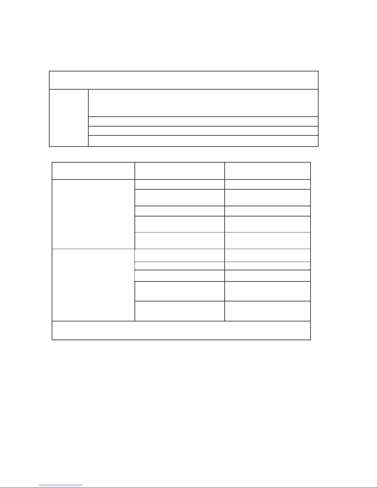
46
General
Detenga inmediatamente el acondicionador si se produce algún de las averías siguientes. Desconecte la alimentación elétrica y llame al centro de asistencia al cliente más próximo.
El piloto indicador de funcionamento o algún otro indicador parpadea rápidamente (5 veces por
segundo) y el paradeo no se corrige desconectando la alimentación e volviéndola a conectar.
El fusible se quema o salta el disyuntor con mucha frecuencia.
Ha penetrado agua o algún objeto en la unidad.
El mando a distacia no funciona o funciona mal.
Otras situaciones anórmalas.
Problema
Avería
Causa
Qué hay que hacer?
La unidad no se pone en marcha
Corte de energía elétrica Espere a que se restablezca
Puede haberse desconectado la unidad
Compruebe que el enchufe está
bien colocado en la base.
Puede haberse fundido el fusible
Sustitúyalo
Se pueden haber agotado las pilas
del mando a distancia
Cambie las pilas
No es pueden haber agotado las
pilas del mando a distancia
Espere o cancele el ajuste del programador
La unidad no enfría ni calienta
muy bienla sala (solo en modelos
con refrigeración y calefacción)
aunque sale aire del acondicionador
La temperatura ajustada que no es
adecuada
Ajuste la temperatura corretamente
El filtro de aire está colmatado
Limpie el filtro de aire
Está obstruida la entrada o la salida
de aire de las unidades interior o
exterior
Están abiertas las puertas o ventanas
Ciérrelas
Elimine las posibles obstrucciones
y vuelva a poner en marcha la
unidad
Se ha activado la proteción de 3
minutos del compresor.
Espere
Si no se resuelve el problema. llame al concesionario o al centro de asistencia al cliente más próximo. Describa con detalle la avería y el modelo de la unidad.
Notas: No intente reparar el aparato usted mismo. Acuda siempre a un servicio técnico autorizado.
7. PROBLEMAS Y SUS CAUSAS

47
8. INSTALACIÓN
Unidad interior
• No exponga la unidad interior a la acción del calor o el vapor.
• Elija un lugar donde no haya obstáculos por delante de la unidad ni a su alrededor.
• Asegúrese de que hay salida fácil para el tubo de vaciado de condensación.
• No lo instale cerca de una puerta.
• Asegúrese de que el aparato tiene más de 12 cm libres a cada lado.
• Utilice un detector de metales para localizar clavos y no dañar innecesariamente la pared.
• El tubo debe tener al menos 3 metros para reducir al mínimo las vibraciones y los ruidí
• La unidad interior debe instalarse en la pared a una altura de 2,3 metros o más sobre i suelo.
• La unidad interior debe quedar a 15 cm del techo como mínimo.
• Cualquier variación de la longitud del tubo puede obligar a ajustar la carga de refrigerante.
Unidad exterior
• Si se coloca un toldo o similar sobre la unidad exterior para protegerla de la acción directa del sol o de la lluvia, asegúrese de que
no limita la radiación de calor desde el condensador.
• El hueco libre a la izquierda y por detrás de la unidad debe medir al menos 30 cm. Por delante de la unidad deben quedar al menos
200 cm libres, y al menos 60 cm por el lado de las conexiones (lado derecho).
• No coloque animales o plantas en la trayectoria de entrada o salida del aire.
• Tenga en cuenta el peso del acondicionador y elija un lugar donde el ruido y la vibraciones no planteen problemas.
• Elija un lugar tal que el aire caliente y los ruidos del acondicionador no molesten a los vecinos.
• Monte la unidad exterior sobre una base rígida para reducir las vibraciones y los ruidos.
• Oriente la salida de aire de modo que éste no se vea obstaculizado.
• Si el lugar de instalación esté expuesto a vientos fuertes, como ocurre cerca del mar, asegúrese de que el ventilador funciona
correctamente colocando la unidad paralela a la pared o montando un cortavientos.
• Instale la unidad de forma que no entre el viento, sobre todo en zonas expuestas a vientos fuertes.
• Si debe suspender la unidad, el soporte debe cumplir los requisitos técnicos indicados en el diagrama correspondiente. La pared
de instalación debe ser de ladrillo macizo, hormigón u otro material de solidez similar; si no es así, es preciso reforzar la estructura
y amortiguar el soporte. Los anclajes del soporte a la pared y del acondicionador al soporte deben ser fuertes, estables y ables.
• Asegúrese de que no hay obstáculos que obstruyan la emisión de aire.
Instalación en una cubierta:
• Si monta la unidad exterior en una estructura de cubierta, no olvide nivelarla. Compruebe que la estructura de la cubierta y el
método de anclaje son adecuados para colocar la unidad.
• Consulte los reglamentos locales de montaje en cubiertas. Si monta la unidad exterior en una cubierta o un muro exterior, el ruido
y las vibracioni pueden ser excesivas; asimismo, la instalación puede clasicarse como imposible de mantener.
2
≤
250 cm
0
2 0
≤ 60 cm
≤ 50 cm
≤ 15 cm
≤ 15 cm
≤ 15 cm
≤15 cm
≤15 cm
≤ 60 cm

48
1. Colocación de la placa de instalación
1. Coloque la placa de instalación horizontalmente sobre algú elemento estructural de la pared y de modo que quede sitio a su
alrededor.
2. Si la pared es de ladrillo, hormigón o similar,perfore en ella ocho (8) orificios de 5 mm de diámetro. Introduzca tacos de anclaje
para los tornillos de montaje adecuados.
3. Monte la placa de instalación en la pared con ocho (8) tornillos de tipo "A".
Monte la placa de instalación y taladre los orificios en la pared teniendo en cuenta la estructura de ésta y los puntos de montaje
correspondientes de la placa. (Salvo indicación en contrario, las dimensiones se dan en mm.)
2. Taladre un orificio en la pared
1. Determine las posiciones de los orificios de acuerdo con el diagrama de la figura 5. Taladre un (1) orificio (O 65 mm) ligeramen
-
te inclinado hacia el exterior.
2. Utilice siempre un pasamuros cuando el orificio atraviese una rejilla o chapa metálica o similar.
3. Instalación de las tuberías de conexión y desagüe
Desague
1. Tienda el manguito de desagüe con pendiente hacia
abajo. No lo coloque en ninguna
de las posiciones ilustradas a continuación.
2. Si prolonga el tubo de desagüe, aisle la pieza de conexión de la prolongación con
una funda protectora; no deje suelto el tubo de desagüe.
Tubo de conexión
1. Para sacar los tubos por la izquierda o la derecha, retire las tapas semipunzonadas correspondientes del panel lateral.
• Explique al cliente que debe guardar la tapa de las tuberías por si fuera preciso volver a utilizarla en caso de traslado del apara
-
to.
2. Para sacar las tuberías derecha o izquierda por detrás, siga estas instrucciones. Doble el tubo de conexión para que discurra a
43 mm de la pared o menos.
3. Sujete el extremo del tubo de conexión. (Consulte Apretado de las conexiones en CONEXIÓN DE LAS TUBERÍAS DE REFRIGERANTE)
Instalación de la unidad interior
1. Pase el tubo por el orificio de la pared.
2. Coloque la garra superior de la parte trasera de la unidad i nterior en el
gancho superior de la placa y mueva la unidad hacia los lados para comprobar que ha quedado bien enganchada.
3. Podrá conectar cómodamente las tuberías levantando la unidad con una
almohadilla dispuesta entre ella y la pared. Retírela después de tender las
tuberías.
4. Empuje la parte inferior de la unidad hacia la parte superior de la pared. A continuación, muévala hacia los lados y en vertical
para comprobar que está enganchada firmemente.
Empaquetado de los tubos
Una los tubos, los cables de conexión y el desagüe con cinta bien apretada y extendida de
forma uniforme, como ilustra la figura 10.El agua condensada de la parte trasera de la unidad se recoge en un recipiente y es evacuada fuera de la habitación. No coloque nada en
el recipiente.
IMPORTANTE
• Conecte primero la unidad interior y después la exterior.
• No saque los tubos directamente por detrás de la unidad interior.
• Tenga cuidado para no dejar flojo el tubo de desagüe.
• Aisle térmicamente ambas tuberías auxiliares.
• Asegúrese de que el tubo de desagüe se encuentra en la parte más baja del conjunto.Si
lo coloca por encima, la bandeja de vaciado podría rebosar hacia el interior de la unidad.
• No cruce el cable de alimentación eléctrica ni lo trence con otros cables.
• Tienda el tubo de desagüe hacia abajo, de forma que el agua condensada fluya sin obstáculos.
8. INSTALACIÓN
Unidad interior
Recolector de
condensado
Cables eléctricos
Descarga condensado
Cinta
aislante
Tubería para
el refrigerante
Capacidad en (W) Longitud del tubo de
conexion minima (m)
Longitud del tubo
de conexion L(m)
Diferencia en el nivel
H (m)
Cantidad extra de refrigerante que se
debe cargar (g/m), si L(m) > 5 m
2600 W ~ 5300 W
5 15 10 20
7000 W 5 25 10 50

49
8. INSTALACIÓN
Conexiones electricas
Conecte el cable a la unidad interior
1. El cable de conexión interior-exterior debe ser del tipo adecuado.
2. Levante el panel de la unidad interior y retire el tomillo; a continuación retire la tapa de la ventanila.
3. Conecte los cables a los terminales de acuerdo con sus marcas.
4. Cubra los cables que no se conecten con cinta aislante, de forma que no toquen ningún componen
te eléctrico.
Conecte el cable a la unidad exterior
1. Retire la tapa de los componentes eléctricos de la unidad exterior.
2. Conecte los cables a los terminales siguiendo los números de identificación de los bloques de termi
nales interior y exterior.
3. Para impedir que entre agua, forme un bucle descendente con el cable, como ilustra el diagrama de
instalación de las unidades interior y exterior.
4. Aisle los cables no utilizados (conductores) con cinta de PVC. Dispóngalos de forma que no toquen
ningún componente eléctrico o metálico.
Cables específicos
UNIDAD INTERIOR
Panel Cables de conexiòn
Cubierta
UNIDAD EXTERIOR
ON/OFF MONO
Capacidad (W)
Cable de conexión de la alimentación Cable de conexión unidades interior y exterior Alimentación
principal
Sección Sección
2600 W, 3500 W 1,5 mm² x 3 1,5 mm² x 5
A la unidad
interior
5300 W 2,5 mm² x 3 2,5 mm² x 3 + 1,5 mm² x 2
7000 W 2,5 mm² x 3 2,5 mm² x 3 + 1,5 mm² x 3
YEGN
YEGN
BU BK VT OG
BU BK VT OG
N(1) 2 4 5
N(1)
2 4 5
YEGN
YEGN
BU BK BN VT
OG
BU BK BN VT
OG
N(1) 2 3 4 5
N(1) 2 3 4 5
BU BK BN VT OG
BU BK BN VT OG
YEGN
YEGN
YEGN
N(1) 2 3 4 5
A UNIT: B UNIT:
N(1)
2 3 4
5
L
N
BU BK BN VT OG
N(1)
2 3 4
5
BU BK BN VT OG
YEGN
N(1) 2 3 4 5
N(1)
2 3
N(1)
2 3
BU
BK BN
BNBKBU
YEGN
YEGN
ON/OFF MONO: 2600 W, 3500 W, 5300 W ON/OFF DUAL: (2 X 2600 W), (2600 W + 3500 W), (2 X 3500 W)
ON/OFF DUAL
Capacidad (W)
Cable de conexión de la alimentación Cable de conexión unidades interior y exterior Alimentación
principal
Sección Sección
2600 W, 3500 W 1,5 mm² x 3 1,5 mm² x 6
A la unidad exterior
DC INVERTER MONO
Capacidad (W)
Cable de conexión de la alimentación Cable de conexión unidades interior y exterior Alimentación
principal
Sección Sección
2600 W 1,5 mm² X 3 1,5 mm² x 4
A la unidad interior
3500 W ~ 7000 W 2,5 mm² X 3 2,5 mm² x 4 A la unidad interior
ON/OFF MONO: 7000 W DC INVERTER MONO: MOD. 2600 W, 3500 W, 5300 W, 7000 W

50
8. INSTALACIÓN
Conexion de las tuberias
1. Abocardados
La principal causa de fuga de refrigerante es un abocardado defectuoso.
Efectúe correctamente el abocardado siguiendo el procedimiento siguiente.
A: Corte los tubos y el cable.
1. Mida la distancia entre las unidades interior y exterior.
2. Corte las tuberías un poco más largas de la distancia medida.
3. Corte un trozo de cable 1,5 m más largo que el tubo.
B: Eliminación de las rebabas
1. Elimine totalmente todas las rebabas del corte de los tubos.
2. Mantenga el tubo de cobre boca abajo mientras elimina las rebabas para que
no caigan en su interior.
C: Colocación de las tuercas
Retire las tuercas para uniones abocardadas de las unidades interior y exterior
y ensártelas en la tubería cuando termine de eliminar las rebabas (no es posible
montarlas después del abocardado).
D: Abocardado
Sujete firmemente la tubería de cobre en una terraja de las dimensiones indicdas
en la tabla siguiente.
Diam. E (mm) A(mm)
Max. Min
Φ6,35 1,3 0,7
Φ9,35 1,6 1
Φ12,7 1,8 1
Φ16 2 1
Apriete de la conexión
• Alinee los centros de los tubos.
• Apriete la tuerca con los dedos todo lo que pueda y luego siga con una llave fija
y una dinamométrica, como ilustra la figura.
IMPORTANTE
• Un par de apriete excesivo puede romper la tuerca en determinadas condiciones
de la instalación.
Diam. E. (mm) Par de apriete (N.m)
Φ 6 15 ~ 20
Φ 9,52 31 ~ 35
Φ 12 50 ~ 55
Φ 16 60 ~ 65
Φ 19 70 ~ 75

51
8. INSTALACIÓN
Unidad interior
Unidad exterior
Valvula manometro
Tubo flexible de cargo
Bombona gas nitrógeno
(en posición vertical)
Purga de aire
La acumulación de aire y humedad en el sistema de refrigeración provoca los siguientes
efectos perjudiciales:
• Aumenta la presión del sistema.
• Aumenta el consumo eléctrico.
• Reduce el rendimiento de la refrigeración o la calefacción.
• El agua presente en el circuito de refrigerante puede congelarse y obstruir los tubos
capilares.
• El agua puede producir corrosión de los componentes del sistema de refrigera ción.
Por tanto, hay que comprobar la presencia de fugas en la unidad interior y en los tubos
que la conectan con la unidad exterior y eliminar del sistema los gases no condensables y
la humedad.
Purga del aire con bomba de vacío
• Preparación
Compruebe que se han conectado todos los tubos (tanto de líquido como de gas) entre las
unidades interior y exterior, y que se han terminado las conexiones eléctricas para efectuar
la prueba. Retire las tapas de las válvulas de servicio de los lados de gas y líquido de la
unidad exterior. Observe que esas válvulas de la unidad exterior están cerradas en esta
etapa.
• Longitud del tubo y cantidad de refrigerante:
• Si cambia de sitio la unidad, vacíela con una bomba de vacío.
• Asegúrese de que el refrigerante añadido al acondicionador está siempre en estado
líquido.
Precauciones para manipular la válvula de servicio
• Abra el vastago de la válvula hasta que tropiece con el tope. No trate de abrirlo más.
• Apriete firmemente el capuchón del vastago con una llave o similar.
• Apriete el tapón del vastago con una llave dinamométrica (vea la tabla de pares de
apriete en la página anterior).
Uso de la bomba de vacío
(Consulte el manejo de la válvula del colector en el manual correspondiente.)
1. Apriete a fondo las tuercas para unión abocardada A, B, C, D, conecte el latiguillo de
baja presión de los manómetros a la toma de presión de la válvula de servicio en la línea
de gas.
2. Conecte el latiguillo a la bomba de vacío.
3. Abra del todo la válvula de baja del manómetro.
4. Ponga en marcha la bomba de vacío, afloje ligeramente la tuerca para unión
abocardada de la válvula de baja del lado del tubo de gas y compruebe que entra aire (el
ruido de funcionamiento de la bomba de vacío cambia y el manómetro indica O en vez de
negativo).
5. Una vez completo el vacio, cierre del todo la válvula de baja de los manómetros y pare
la bomba, Haga un vacio de 15 minutos o más, y compruebe que el manovacuómetro
indica -76cmHg. (-1x10⁵Pa).
6. Gire el vastago de la válvula de servicio B unos 45° en sentido contrario a las agujas del
reloj durante 6-7 segundos después de que el gas haya salido y luego apriete de nuevo la
tuerca. Asegúrese de que el manovacuómetro indica una presión ligeramente mayor que
la atmosférica.
7. Retire el latiguillo de carga del latiguillo de carga de presión baja.
8. Abra del todo los vastagos de las válvulas de servicio B y A.
9. Apriete a fondo el tapón de la válvula de servicio.
cargar
–5)x30 g
tapa de
control
capuchón
llave hexagonal
tapón de drenaje
Lado gas
Lado liquìdo
tablero de bornes
Válvula de 2 vías
abierta
Válvula de 3 vías
cerrada
Ø
Unidad interior
Unidad exterior
Válvula manómetro
Abierta
Cerrada
Bomba de vacìo
Indicador de presion
Indicador de presion

52
FRANÇAIS

53
TABLE DE MATIERES
1. Informations importantes . . . . . . . . . . . . . . . . . . . . . . . . . . . . . . . . . . . . . . . . . . . . . . . . . . . . . . . . . . .54
2. Composantes . . . . . . . . . . . . . . . . . . . . . . . . . . . . . . . . . . . . . . . . . . . . . . . . . . . . . . . . . . . . . . . . . . . .55
3. Display . . . . . . . . . . . . . . . . . . . . . . . . . . . . . . . . . . . . . . . . . . . . . . . . . . . . . . . . . . . . . . . . . . . . . . . . . .55
4. Télécomande . . . . . . . . . . . . . . . . . . . . . . . . . . . . . . . . . . . . . . . . . . . . . . . . . . . . . . . . . . . . . . . . . . . . .56
5. Entretien . . . . . . . . . . . . . . . . . . . . . . . . . . . . . . . . . . . . . . . . . . . . . . . . . . . . . . . . . . . . . . . . . . . . . . . . 60
6. Opérations et performances . . . . . . . . . . . . . . . . . . . . . . . . . . . . . . . . . . . . . . . . . . . . . . . . . . . . . . . . .61
7. Problèmes et leurs causes . . . . . . . . . . . . . . . . . . . . . . . . . . . . . . . . . . . . . . . . . . . . . . . . . . . . . . . . . . 62
8. Installation . . . . . . . . . . . . . . . . . . . . . . . . . . . . . . . . . . . . . . . . . . . . . . . . . . . . . . . . . . . . . . . . . . . . . . .63

54
1. INFORMATIONS IMPORTANTES
N'effectuez aucune opération exigeant l'ouverture de
l'appareil
Electrocution par contact avec des composants sous tension.
Lésions sous forme de brûlures dues à la présence de composants surchauffés ou de blessures provoquées par des
sail-lies et des bords tranchants
N'effectuez aucune opération exigeant ladépose de l'appareil
Electrocution par contact avec des composants sous tension.Lésions sous forme de brûlures dues au froid provoquées parle gaz
s'échappant des tuyaux débranchés
N'utilisez pas la che du câble d'alimentation électrique
pour brancher ou arrêter l'appareil
Electrocution provoquée par le mauvais état du câble, de lache ou de la prise
N'abîmez pas le câble d'alimentation électrique Electrocution provoquée par des ls sous tension dénudés
Ne posez jamais d'objets sur l'appareil Lésions provoquées par la chute de l'objet par suite de vi-
brations
Ne montez pas sur l'appareil Lésions provoquées par la chute de l'appareil
Ne grimpez pas sur des chaises, des tabourets, des
échelles ou des supports instablespour nettoyer l'appareil
Lésions provoquées par chute d'une hauteur élevée ou parcoupure (échelle pliante)
N'effectuez aucune opération de nettoyage del'appareil
sans avoir auparavant éteint l'appareil, débranché la che ou désactivé l'interrupteur dédié
Electrocution par contact avec des composants sous tension
Ne permettez pas à des enfants ou à des personnes
inexpérimentées d'utiliser l'appareil
Endommagement de l'appareil dû à un usage impropre
Ne dirigez pas le ux de l'air vers des plans decuisson ou
des poêles à gaz
Explosions, incendies ou intoxications dus au gaz s'échap-
pantdes injecteurs qui alimentent les ammes éteintes par
le ux d'air
Ne glissez pas les doigts dans les bouches desortie de
l'air et dans les grilles d'aspiration de l'air
Electrocution par contact avec des composants sous tension.
Lésions provoquées par des coupures
Ne buvez pas l'eau condensée Lésions dues à intoxication
Si vous sentez une odeur de brûlé ou si vousvoyez de
la fumée s'échapper par l'appareil,coupez l'alimentation
électrique, ouvrez lesfenêtres et appelez un technicien
Lésions dues à des brûlures ou à inhalation de fumée.
N'effectuez aucune opération exigeant ladépose de l'appareil
Inondations dues à l'eau s'échappant des tuyaux débranchés
Ne posez jamais d'objets sur l'appareil Endommagement de l'appareil ou des objets placés en des-
sous par la chute de l'appareil détaché de ses supports.
N'utilisez pas d'insecticides, de solvants ou deproduits
de nettoyage agressifs pour l'entretien de l'appareil
Endommagement des parties peintes ou en plastique
N'utilisez pas l'appareil pour des usagesautres qu'un
usage domestique habituel
Endommagement de l'appareil du fait d'une surcharge defonctionnement.Endommagement des objets indûment traités.
Ne permettez pas à des enfants ou à des personnes
inexpérimentées d'utiliser l'appareil
Endommagement de l'appareil dû à un usage impropre
Ne dirigez pas le ux de l'air vers des objetsde valeur,
des plantes ou des animaux
Endommagement ou dépérissement à cause de l'excès defroid/chaleur, humidité, ventilation.
N'utilisez pas le climatiseur trop longtempsdans des conditions d'humidité dépassant 80%
Endommagement d'objets par suintement excessif de l'appareil.
REGLEMENTATION: RISQUE :

55
2. COMPOSANTES
Unitè interieure
Unitè exterieure
3. DISPLAY
(1) LED recivitore segnale
(2) Indicateur operation
Cet indicateur clignote après la mise en marche de l’appareil et s’allume définitivement lors du fonctionnement.
(3) Indicateur de chauffage
Cet indicateur s’allume lors du fonctionnement du climatiseur en mode chauffage.
(4) Indicateur de refroidissement
Cet indicateur s’allume lors du fonctionnement de l’appareil en mode refroidissement.
(5) Indicateur température réglage
Indique les paramètres de température de lors du fonctionnement de l’appareil.
(6) Indicatore di deumidificazione
Cet indicateur s’allume lors du fonctionnement de l’appareil. en mode de déshumidification.
(1)(2)(3)
(4) (5) (6)
(1) Admission d’air
(2) Panneau frontal
(3) Comande manuelle
(4) Décharge d’air
(5) Déflecteur d’air vertical
(6) Filtre à air
(7) Admission d’air
(8) Tubo de conexión
(9) Tuyau de vidange
(10) Décharge d’air
(11) Admission d’air
(12) Télécommande
(1)
(4)
(2)
(6)
(5)
(11)
(9)
(3)
(7)
(10)
(1)
(2)
(4)
(5)
(6)
(11)
(12)
(12)
(10)
(8)
(7)
(3)
(9)
(8)
23
8888:
FAN
HOUR
ON-OFF
AUTO
OPER
FAN
CLOCK
TIMER OFF
TIMER ON
LIGHTSLEEPTURBO
ON/OFF MODE
BLOW TEMP
°F
°C
+
-
23
8888:
FAN
HOUR
ON-OFF
AUTO
OPER
FAN
CLOCK
TIMER OFF
TIMER ON
LIGHTSLEEPTURBO
ON/OFF MODE
BLOW TEMP
°F
°C
+
-

56
4. TELECOMMANDE
4. TELECOMMANDE
DESCRIZIONE FUNZIONI DEI TASTI DEL TELECOMANDO
1) Touche
ON/OFF pour mettre en marche et arrêter le climatiseur.
2) Touche
TEMP pour régler la température ambiante et le minuteur: "+" pour l'augmenter, "-" pour la diminuer.
3) Touche FAN pour programmer la vitesse du ventilateur en choisissant entre Automatique - basse - moyenne - haute:
4) La touche CLOCK permet de programmer l'horaire courant.
5) Touche BLOW active uniquement dans les modes de fonctionnement REFROIDISSEMENT et
DESHUMIDIFICATION.
6) Touche TURBO : active/désactive le mode de refroidissement / chauffage rapide.
7) Touche SLEEP pour le fonctionnement nocturne pour sélectionner/annuler le mode Sleep
indépendamment du mode de fonctionnement du climatiseur.
8) Touche TEMP permet de visualiser sur l’afficheur de l’unité la température de consigne et
ambiante.
9) Touche LIGHT active et désactive l’afficheur de l’unité.
10) Touche de sélection
TIMER.
11) Touche
pour activer/désactiver le mouvement automatique du déflecteur d'air.
12) Touche
MODE pour sélectionner le mode de fonctionnement.
AUTO - COOL - DRY - FAN - HEAT :
AUTO: le climatiseur sélectionne automatiquement le mode de fonctionnement
le plus approprié (HEAT, DRY, FAN, COOL) en fonction de
la température ambiante.
COOL: l'unité commence à fonctionner si la température programmée est plus basse que la température ambiante.
DRY: pour la déshumidification
FAN: l'unité met automatiquement en circulation l'air ambiant.
HEAT: l'unité commence à fonctionner si la température programmée est plus haute que la température ambiante.
DESCRIPTION DES INDICATEURS DE l'AFFICHEUR
1) Indicateur du mode AUTO.
2) Indicateur du mode
COOL.
3) Indicateur du mode
BLOW.
4) Indicateur du mode
DRY.
5) Indicateur du mode
TURBO.
6) Indicateur du mode de ventilation
FAN seulement.
7) Indicateur du mode
HEAT.
8) Indicateur
CLOCK.
9 Indicateur du mode
SLEEP.
10) Indicateur
TEMP.
11) Indicateur du déflecteur.
12) Indicateur du mode
LIGHT.
13) Indicateur du mode
LOCK.
14) Indicateur du mode
TIMER ON.
15) Plage d'affichage température
16) Led de confirmation signal transmis.
17) Indicateur de vitesse du ventilateur.
AUTO
AFFICHEUR
23
88 88:
FAN
HOUR
ON-OFF
AU TO
OPER
FAN
CLOCK
TIMER OFF
TIMER ON
LIGHTSLEEPTURBO
ON/OFF MODE
BLOW TEMP
°F
°C
+
-
1
2
3
4
5
6
7
8
9
10
11
12
23
88 88:
FAN
HOUR
ON-O F F
°C
AUTO
OP ER
1
2
3
4
5
6
7
8
9
10 11 12
14
13
15
1617

57
4. TÉLÉCOMMANDE
Comment insérer/remplacer les piles
Insérez deux piles neuves alcalines 1,5 V de type AAA.
(1) Enlever le couvercle du compartiment des batteries en le faisant glisser dans la
direction des flèches.
(2) Insérer les nouvelles piles alcaline AAA en respectant la polarité et fermer le couvercle des vaines batteries.
NOTES
- Ne jamais mettre ensemble des batteries neuves et vieilles ou des batteries de type
différents. Ceci peut causer un mal fonctionnement de l’unité.
- Si la télécommande ne va pas utiliser pour une longtemps, il faut enlever les batte
ries pour éviter des endommagements causés par d'éventuelles pertes
- Les batteries doivent être changer lorsque l’unité intérieure ne reçoit aucun signal son
-
neur "bip" ou bien si l'indicateur de transmission sur la télécommande ne s'allume pas.
- Placer la télécommande dans son support fixé au mure (pour assurer la transmission
correcte du signal).
Mode d’usage
- Tenir la télécommande d’une façon à permettre au signal de rejoindre le récepteur de
l'unité intérieure.
- Une distance supérieure à 7m est permise.
Mode de fonctionnement
(1) Sélection de mode
Claque fois que la touche MODE vient d’être appuyée, le mode de fonctionnement se
change dans la séquence suivante:
AUTO ( ) Refroidissement ( ) Deshumidification ( ) Vent. ( ) Chauffage ( )
(2) Mode de ventilation
Chaque fois où la touche "FAN" vient d’être appuyée, la vitesse de ventilation se change dans la séquence suivante: Auto
Basse( ) Moyenne( ) haute( )
En mode de "VENTILATION", seulement la "AUTO", "Haute", "Moyenne" et "Basse"
vitesse du ventilateur sont disponibles. En mode de "DESHUMIDIFICATION" le ventila-
teur est automatiquement en "Basse" vitesse, la touche "FAN" est inactive dans ce cas.
(3) Température de régulation
Chaque fois la touche "+" vient d’être appuyée, la température régulée augmente de1°C.
Chaque fois la touche "-" vient d’être appuyée, la température régulée diminue de 1°C.
(4) Allumage
Appuyer cette touche ON/OFF, quand l'appareil reçoit le signal, l'indicateur de
FONCTIONNEMENT de l'unité intérieure s’illumine.
Note:
- Changer le mode durant le fonctionnement, parfois l'unité ne répond pas immédiatement. Temps d’attente est de 3 minutes.
- Au début de fonctionnement en mode de chauffage, le flux d'air ne se déchargera pas
immédiatement. Le flux d'air sera diffusé lorsque la température de l'échangeur de
chaleur de l'unité intérieure augmente, après environ 2 ou 5 minutes.
- Il faut attendre 3 minutes avant le nouveau redémarrage de l’appareil.
2
1
3
4
23
8
88
8
:
F
AN
HO
U
R
O
N
-
O
F
F
A
U
T
O
O
P
E
R
F
A
N
C
L
O
C
K
T
I
ME
R
OF
F
TI
ME
R
O
N
L
I
G
H
T
S
L
E
E
P
T
U
R
B
O
O
N
/
O
FF
M
O
D
E
B
L
O
W T
E
M
P
°
F
°
C
+
-
23
88
88:
FA
N
HO
UR
ON
-O
FF
AU
TO
OP
ER
FA
N
CLO
CK
TI
MER
OF
F
TI
MER
ON
L
IGH
T
SLEEP
T
URB
O
ON
/OFF
MO
DE
BL
OW
T
EMP
°F
°C
+
-
Intervalle de variation de la température de régulation
Chauffage, Refroidissement 16°C - 30°C
Déshumidification N’est pas disponible
Ventilation N’est pas disponible

58
4. TÉLÉCOMMANDE
Contrôle de la direction du flux d’air
Le flux d'air vertical est automatiquement régulé sur un angle particulier en concordance avec le mode de fonctionnement après l'allumage de l'unité.
Note: La direction du flux d'air peut aussi être régulée en appuyant sur la touche " " dans la télécommande.
* Contrôle vertical du flux d'air (avec la télécommande)
On utilise la télécommande pour ajuster le flux d'air sur divers angles ou sur un angle particulier préférable.
Oscillation du flux d'air
Lors du démarrage, le déflecteur prend une position prédéterminée. Pour régler la direction du flux d'air
qui sort de l'unité intérieure appuyer sur la touche " ". En appuyant une fois le déflecteur continue à bouger en mélangeant l'air
dans la pièce. Une deuxième pression de la touche " ", bloque le déflecteur
* Contrôle horizontal du flux d'air (avec les mains)
On tient avec les mains les barres de régulation horizontale des ailettes pour changer le flux d'air
comme indiqué dans la figure.
Notes:
- La figure de l'unité peut sembler différente de celle du climatiseur que vous aviez acquis.
- Ne pas tourner manuellement l'ailette de régulation verticale pour éviter des mal fonctionnements. Si cela arrive, éteindre
l'unité d'abord et détacher l'alimentation, puis reconnecter de nouveau l'alimentation.
- Il est conseillable de ne pas laisser l'ailette verticale s'incliner vers le bas durant le temps de refroidissement ou en déshumidification pour empêcher la formation de la condensée.
FUNZIONAMENTO AUTO
Durante il funzionamento AUTO, l’unità seleziona automaticamente HEAT, DRY, FAN, COOL in base alla temperatura ambiente.
Attivazione della modalità AUTO:
Prima selezionare sul telecomando la modalità AUTO mediante il tasto MODE.
La modalità di funzionamento e la temperatura di impostazione sono funzione della temperatura ambiente secondo la seguente tabella.
FONCTIONNEMENT EN MODE AUTO
Durant le fonctionnement AUTO, l'unité sélectionne automatiquement HEAT, DRY, FAN, COOL en fonction de la température intérieure.
Régulation du mode AUTO :
Allumer le climatiseur, puis sélectionner le mode AUTO sur la télécommande en appyant sur la touche MODE.
La sélection automatique du mode de fonctionnement et la température sont déterminées en foction de la température intérieure
selon le tableau suivant:
REMARQUE:
- En mode AUTO la température n'est pas affichée.
- Il peut arriver que l'appareil ne délivre pas d'air pendant qu'il est en marche.
- L'appareil ne commence pas toujours à fonctionner immédiatement après avoir modifié le mode de travail.
SELECTION DU MODE DE FONCTIONNEMENT
Appuyer sur la touche "MODE" pour sélectionner le mode de fonctionnement désiré en choisissant
parmi les suivants: AUTO - COOL - DRY - FAN - HEAT.
1) Mode AUTO: pour sélectionner cette fonction, appuyer sur la touche "MODE" jusqu'à l'apparition sur
écran de l'indicateur . Le climatiseur définit automatiquement le mode de fonctionnement (HEAT, DRY,
FAN, COOL) selon la température ambiante.
2) Mode Refroidissement: pour sélectionner cette fonction, appuyer sur la touche "MODE" jusqu'à l'apparition sur écran de l'indicateur . L'unité commence à fonctionner si la température programmée est
plus basse que la température ambiante.
3) Mode DRY - déshumidification: pour sélectionner cette fonction, appuyer sur la touche "MODE"
jusqu'à l'apparition sur écran de l'indicateur . L'unité commence à fonctionner en mode refroidissement
pour atteindre rapidement la température ambiante désirée.
4) Mode FAN - ventilation: pour sélectionner cette fonction, appuyer sur la touche "MODE" jusqu'à l'ap-
parition sur écran de l'indicateur ; le mode FAN permet la circulation automatique de l'air dans la pièce.
5) Mode HEAT -chauffage: pour sélectionner cette fonction, appuyer sur la touche "MODE" jusqu'à l'apparition sur écran de l'indicateur . L'unité commence à fonctionner si la température programmée est
plus haute que la température ambiante.
FEEL
M
ODE
1
2
3
4
5
12
30
:
22
FAN
°C
AU
TO
O
PER
FA
N
CLO
CK
TI
MER
OF
F
TIMER
ON
L
IGH
T
SLEEP
T
URBO
ON/OFF
MO
DE
BLOW
T
EMP
+
-
FA
N
CLO
CK
TI
MER
OF
F
TIMER
ON
L
IGH
T
SL
EEPT
URBO
ON/OFF
MO
DE
BLOW
T
EMP
+
-
E
Temp. intérieure Opération Température désirée
Inférieure à 21°C
Chauffage
18°C
21°C ~ 24°C
Ventilation
/
Supérieure à 24°C Refroidissement
25°C
Impression
Touche
Procédure de régulation
Non confortable à cause du volume
inadéquat du flux d’air
FAN
La vitesse du ventilateur de l’unité intérieure s’alterne entre haute, moyenne e basse vitesse
chaque fois cette touche vient appuyée.
Non confortable à cause du la direction inadéquat du flux d’air
SWING
En appuyant cette touche une seule fois, l’ailette du flux d’air verticale oscille pour changer la direction
du flux d’air. En appuyant de nouveau la même touche l’oscillation de l’ailette s’arrête.
Pour la direction horizontale du flux d’air, voir la page précédente.
Mode de fonctionnement
Direction de flux
REFROIDISSEMENT, DESHUMUDIFICATION Horizontale
* CHAUFFAGE, VENTILATION Vers le bas

59
4. TÉLÉCOMMANDE
PROGRAMMATION DE L'HORLOGE
Appuyer sur la touche CLOCK pour ajuster l'horloge, utiliser les touches "+" et "-" après pour ajuster l’heure correcte, appuyer de
nouveau, la touche CLOCK pour la confirmer.
- Appuyez une fois sur les touches pour augmenter / diminuer l'horaire d'1 minute.
- Appuyez pendant 1,5 secondes pour augmenter / diminuer l'horaire de 10 minutes.
Mode TIMER
Appuyer les touches Timer ON/OFF pour réguler la programmation horaire et donc l’allumage et l’extinction du climatiseur.
Comment réguler TIMER ON
Appuyer sur la touche TIMER ON pour ajuster la programmation horaire de l’allumage du climatiseur.
1) Appuyer la touche TIMER ON,
"ON" clignotera sur l’écran LCD, après utiliser la touche "+" ou "-"
pour réguler l’heure désirée de l’allumage programmé du climatiseur:
- Appuyer la touche "+" ou "-" une fois pour augmeter ou diminuer l’heure avec 1 minute.
- Appuyer la touche "+" ou "-" pour 1.5 secondes pour augmeter ou diminuer l’heure avec 10 minutes.
Note: Si vous ne ajuster pas l’heure entre 10 seconds après avoir appuyé sur la touche TIMER ON,
la télécommande quittera automatiquement le mode TIMER ON.
2) Quand l’heure désirée est visualisée sur l’écran LCD, appuyer sur la touche TIMER ON pour la
confirmation. Un “son” peut-être émis. "ON" s’arrête de clignoter et l'indicateur du TIMER sur l’unité
intérieure s’illumine.
3) Après la visualisation de la régulation TIMER, l'heure actuelle se visualisera sur l’écran de la télécommande.
Comme annuler le TIMER ON
Appuyer de nouveau la touche TIMER ON, un "son" vient d’être émis et après l’indicateur disparu, et le mode TIMER ON, s’annulera.
Note: La procédure est analogue pour ajuster le mode TIMER OFF, pour extection automatique du climatiseur à l’heure de régulation.
AVERTISSEMENT
Si vous ajustez la programmation horaire la télécommande transmit automatiquement le signal d’allumage ou d’extinction à l’unité
intérieure des horaires préfixées.
Par conséquent, il faut maintenir la télécommande dans une place où elle peut transmettre le signal correctement. L’horaire possible de programmation est limité aux 24 heures.
Initialement la fonction TIMER (ON/OFF) est activée près l’heure actuelle.
Le TIMER ne fonctionne pas si les options Timer ON et Timer OFF sont activées sur le même
temps.
Mode SLEEP:
Le mode “SLEEP” peut-être utilisé en mode de CHAUFFAGE ou de REFROIDISSEMENT.
Cette fonction est utile pour une ambiante plus confortable quand se va à dormir.
En mode sleep.
- La vitesse du ventilateur vient régulée sur la basse.
- La température disérée augmente en mode de refroidissement ou diminue en mode chauffage
avec 1°C à intervalles prédéfinis. À partir de 2°C de variation, la machine maintient la température
jusqu'à la huitième heure de fonctionnement en mode "SLEEP" puis s'éteint automatiquement.
Mode TURBO:
Le mode TURBO est utilisé pour démarrer ou arrêter le refroidissement ou le chauffage rapide à
haute vitesse du ventilateur. Dans le mode de fonctionnement TURBO, on peut ajuster la direction
du flux d'air et le timer. Si vous souhaitez quitter le mode TURBO, appuyer une touche quelconque
- TURBO, MODE, FAN ou ON/OFF, l’écran revient au mode original.
Mode BLOW:
A l’extinction de l’unité, après le fonctionnement de REFROIDISSEMENT ou DESHUMIDIFICATION,
ventilez pendant 10 minutes l'évaporateur de l’unité de manière à éviter que l’éventuel eau de condensation résiduelle ne crée des moisissures ou mauvaises odeurs.
Fonctio LOCK:
En appuyant simultanément sur les boutons "+" et "-", la télécommande bloquera le dernier réglage de fonctionnement programmée. Tous les boutons seront désactivés, y compris le bouton
ON/OFF. En appuyant de nouveau sur les boutons "+" et "-", les fonctions des touches seront
activées.
Commutation °C / °F: Appuyez simultanément sur les boutons "MODE" et "-" à unité éteinte, il
sera possible de choisir si visualiser la température en °C ou °F.
TOUCHE EMERGENCY DE L'UNITÉ INTÉRIEURE
Elle permet de démarrer et/ou d'arrêter l'unité en cas de panne de la télécommande. Le mode de
fonctionnement et la température désirée sont réglés automatiquement en fonction de la température ambiante au moment du démarrage de l'unité.
FONCTION AUTO-RESTART
L’unité est programmée pour démarrer automatiquement en cas de coupure de courant électrique.
AUT
O/ST
OP
23
88
88:
FA
N
HO
UR
ON
-O
FF
AU
TO
OP
ER
FA
N
CLO
CK
TI
MER
OF
F
TI
MER
ON
L
IGH
T
SL
EEP
T
URB
O
ON/OFF
MO
DE
BLOW
T
EMP
°F
°C
+
-
25
12
00
:
FAN
HO
UR
ON
-OFF
°C
AU
TO
O
P E
R
ON
-OF
F
00
3 :
O
N -OF
F
23
C
FA
N
CLO
CK
TI
MER
OF
F
TIMER
ON
L
IGH
T
SLEEP
T
URBO
ON/OFF
MO
DE
BLOW
T
EMP
+
-
F
FA
N
CLO
CK
TI
MER
OF
F
TIMER
ON
L
IGH
T
SLEEPT
URBO
ON/OFF
MO
DE
BLOW
T
EMP
+
-
E
E

60
5.ENTRETIEN
II est nécessaire d'éteindre le climatiseur et de le débrancher avant le nettoyage.
Nettoyage de l’unité interieure et du télécommande.
- Utilisez un chiffon sec pour nettoyer l'unité intérieure et la télécommande.
- Un chiffon humidifié à l'eau froide peut éventuellement être utilisé pour nettoyer
l'extérieur de l'unité si elle est très sale.
- Le panneau frontal de l’unité interieure peut être démonté et lavé à l’eau.
Essuyer-le esnsuite avec chifon sec.
- N'utilisez pas de chiffon traité chimiquement pour nettoyer l'unité.
- N'utilisez ni benzène, solvant, poudre à polir ou dissolvant similaire pour le nettoyage. Cela pourrait craqueler ou déformer la surface en plastique.
Nettoyage du filtre à air
Un filtre à air bouché réduit l'efficacité de cette unité.
Veuillez nettoyer les filtres toutes les deux semaines.
1. Ouvrez le panneau de l'unité intérieure et soulevez-le jusqu'à un angle où il
fera click pour le fixer.
2. Agrippez le filtre par sa poignée et soulever-le lègèrement pour le dégager de
son support, retirez-le ensuite.
3. Enlevez le FILTRE À AIR de l'unité intérieure
- Nettoyez le filtre chaque deux semaines
- Nettoyez le filtre à air avec un aspirateur ou avec de l'eau, puis laissez-le
sécher dans un endroit frais.
4. Retirez le filtre électrostatique de son support, tel qu'indiqué sur la figure de
gauche (n'est pas applicable aux unités sans filtre électrostatique).
Ne touchez pas le filtre électrostatique pendant 10 minutes après avoir ouvert la
grille d'admission, cela pourrait causer une décharge électrique.
- Nettoyez le filtre électrostatique avec un détergent neutre ou à l'eau et le laisser
sécher au soleil pendant deux heures.
- Avant de réinstaller le filtre électrostatique, vérifiez que sa couronne et son support sont en bon état.
5. Posez le filtre rafraîchisseur à nouveau à sa place.
6. Insérez la partie supérieure du filtre à air dans l'unité en faisant attention à ce
que les arêtes gauches et droites soient correctement alignées, et positionnez le
filtre.
Entretien
Si l'unité ne va pas être mise en marche pendant un certain temps, veuillez prendre les précautions suivantes:
(1) Faire fonctionner le ventilateur pendant une demi-journée pour bien sécher
l'intérieure de l'unité.
(2) Éteignez le climatiseur et débranchez-le. Enlevez les piles de la télécomman
de.
(3) L'unité extérieure nécessite un entretien et un nettoyage régulier. N'essayez
pas de le faire vous- même. Contactez votre distributeur ou service d'entretien.
Vérifications avant la mise en marche.
- Vérifiez que le câblage n'est pas endommagé ou déconnecté.
- Vérifiez que le filtre à air est bien en place.
- Vérifiez si la décharge et l'admission d'air sont bloqués après une longue période d'inutilisation.
PRECAUTIONS
- Ne touchez pas les parties métalliques de l'appareil lors du retrait du filtre. La
manipulation d'arêtes de métal agressives peut causer des blessures.
- Ne laver pas l'intérieur du climatiseur avec l'eau. L'exposition à l'eau peut
détruire les isolants et provoquer une décharge électrique.
- Coupez l'alimentation électrique via le disjoncteur et le cordon d'alimentation
lors du nettoyage de l'appareil.
ATTENTION
PRÉCAUTIONS
ENTRETIEN

61
6. OPÉRATIONS ET PERFORMANCES
Les circonstances suivantes peuvent se produire pendant le fonctionnement normal.
1. Protection du climatiseur
- Le compresseur met 3 minutes pour redémarrer après un arrêt.
Protection contre l'air froid (seulement sur les modèles réversibles)
- L'unité est conçue pour ne pas décharger d'air froid en mode chauffage quand l'échangeur de chaleur intérieur est dans une des
trois situations suivantes et que la température de thermostat n’a pas été atteinte:
A) Au tout début de la mise en marche.
B) Pendant le dégivrage
C) Si la température de chauffage est basse.
- Pendant le dégivrage, les ventilateurs intérieur et extérieur s'arrêtent (seulement sur les modèles réversibles). Dégivrage (seulement sur les modèles réversibles)
- Du givre peut se former sur l'unité extérieure pendant le cycle de chauffe quand la température extérieure descend et que l'humidité augmente, réduisant les performances de chauffage de l'appareil.
- Dans ces conditions de fonctionnement, le climatiseur arrêtera de chauffer et commencera un cycle automatique de dégivrage.
- La durée de ce cycle varie entre 4 et 10 min, en fonction de la température extérieure et de la quantité de givre qui s'est formé
sur l'unité extérieure.
2. L'unité intérieure émet une buée blanche
- Une buée blanche peut se former à cause d'une grande différence de température entre l'air admis et l'air déchargé en mode
COOL (refroidissement) dans un environnement intérieur relativement humide.
- Une buée blanche due à l'humidité peut se produire après un cycle de dégivrage quand le climatiseur redémarre en mode HEAT
(chauffage).
3. Bruit faible du climatiseur.
- Vous pouvez entendre un léger sifflement quand le compresseur est en marche ou vient de s'arrêter. Ce son est produit par le
flux ou l'arrêt de frigorigène.
- Vous pouvez également entendre un léger grincement quand le compresseur est en marche ou vient de s'arrêter. Ce grincement
est causé par la dilatation due à la chaleur et la contraction due au froid des pièces en plastique de l'unité quand la température
varie.
- Quand les déflecteurs se remettent à leur position initiale au moment de l'allumage, un léger bruit se produit.
4. L'unité intérieure émet de la poussière
Ceci est normal après une longue période d'inutilisation du climatiseur, ou après sa première mise en marche.
5. L'unité intérieure émet une odeur particulière
Cette odeur est due au passage d'odeurs de matériaux de construction, de mobilier ou de fumée au travers de l'unité intérieure.
6. Le climatiseur se met en mode FAN ONLY (ventilation seule) depuis les modes COOL (refroidissement) ou HEAT (chauffage) (seulement sur les modèles réversibles)
Quand la température intérieure atteint la température du thermostat, le compresseur s'arrête automatiquement, et le climatiseur
fonctionne en mode ventilation. Si la température intérieure augmente en mode froid, ou qu'elle descend en mode chauffe, par rapport au thermostat, alors le compresseur se remet en marche (seulement sur les modèles réversibles).
7. De l'eau peut apparaître sur la surface de l'unité intérieure en mode froid si l'humidité relative est importante (supérieure à 80%).
Réglez le déflecteur horizontal au maximum de la décharge et sélectionnez HIGH pour la vitesse de ventilation.
8. Mode chauffage (seulement sur les modèles réversibles)
En mode chauffage, le climatiseur conduit de l'air chaud depuis l'unité extérieure et le libère vers l'unité intérieure. Quand la température extérieure descend, la chaleur de l'air admis par le climatiseur descend également. En même temps, la charge calorifique
du climatiseur augmente à cause de la grande différence entre les températures extérieure et intérieure. Si vous ne parvenez pas
à atteindre une température confortable avec votre climatiseur, nous vous conseillons d'utiliser un dispositif de chauffage supplémentaire.
9. Fonction de redémarrage automatique
Une coupure de courant pendant le fonctionnement éteindra le climatiseur.
Sur les modèles sans dispositif de redémarrage automatique, quand le courant est rétabli, l’indicateur de FONCTIONNEMENT de
l'unité intérieure commence à clignoter. Pour remettre l'appareil en marche, appuyez sur la touche ON/OFF de la télécommande.
Sur les modèles munis d'un dispositif de redémarrage automatique, quand le courant est rétabli, l'appareil se remet en marche
automatiquement avec les paramètres de réglage établis auparavant.
10. Les éclairs ou l'utilisation d'un téléphone portable à proximité de l'appareil peut provoquer son dysfonctionnement. Débranchez
puis rebranchez alors l'appareil. Pour le remettre en marche, utilisez sur la touche ON/OFF de la télécommande.
6. OPÉRATIONS ET PERFORMANCES

62
7. PROBLÈMES ET LEURS CAUSES
En cas de malfonctionnement, mettez immédiatement l’appareil hors tension. Coupez l’alimentation électrique et contactez le service clientèle le plus proche.
L’indicateur de fonctionnement, ou tout autre indicateur, se met à clignoter rapidement (5 Hz)
et malgré le débranchement et rebranchement de l’appareil, il continue à clignoter.
Les fusibles ou le disjoncteur sautent souvent.
L’eau ou autre corps étrange pénètre dans le climatiseur.
La télécommande ne fonctionne pas ou son fonctionnement est anormal.
Autre situation anormale
Problème
Symptôme
Cause
Qu’est ce q’il faut faire?
L’appareil ne démarre pas
Coupure éléctrique Attendre le rétablissement du courant
L’appareil est peut-être débranché
Vérifier que la prise est correcetement branchée
Le fusible peut-être sauté
Remplacer le fusible
Les piles de la télécommande sont
peut-être expirées
Remplacer les piles
La programmation est incorrecte
Attendre ou annuler la programmation
Mauvaise performances de refroidissement ou de chauffage (seulement sur les modèles réversibles) tandis que l’air est déchargé
Température non appropriée du
thermostat
Régler correctement la tempèrature
Le filtre à air est bouché
Nettoyer le filtre à air
Les or ifices d’admis sion ou de
décharge des unités sont bloqués
Des portes ou/et des fenêtres sont
ouvertes
Fermez les portes ou/et les fenêtres
Enlever ce qui obstrue les orifices
avant de redémarer l’appareil
Les 3 minutes de protection du compresseur sont activées.
Attendre
Si les problèmes subsistent, veuillez contacter un distributeur local ou le service de réparation le plus proche.
Assurez-vous d’en leur communiquer les indications précises concernant le type de panne et le modèle de
l’appareil.
Remarque: N'essayez pas de réparer le climatiseur vous-même. Consultez toujours un service de réparation
agréé.

63
8. INSTALLATION
Unité intérieure
• N'exposez pas l'unité intérieure á une source de chaleur ou de vapeur.
• Choisissez un emplacement libre d'obstacles devant et autour de l'unité.
• Assurez-vous que les condensáis peuvent étre facilement ou de vapeur.
• Choisissez un emplacement libre d'obstacles devant et autour de l'unité.
• Assurez-vous que les condensats peuvent étre facilement evacúes.
• N'installez pas cet appareil prés d'une issue.
• Assurez-vous de laisser un espace de plus de 12 cm á gauche et á droite de l'appareil.
• Utilisez un détecteur de métaux pour localiser les montants de cloisons et ne pas abímer les murs pour rien.
• Le tuyau doit mesurer au moins 3 métres pour minimiser les vibrations et le bruit excessif.
• L'unité intérieure doit étre installée sur le mur á une hauteur d'au moins 2,3 métres du sol.
• L'unité intérieure doit étre installée á au moins 15 cm du plafond.
• Toute modication de la longueur du tuyau devra faire l'objet d'un réglage de la charge frigorigéne.
Unitè extèrieure
• Si vous décidez de poser une bache sur l'unité extérieure pour la proteger des rayons solaires ou de la pluie, assurez-vous que
celle-ci ne restreint pas le rayonnement de chaleur du condensateur.
• Assurez-vous de laisser un espace de plus de 30cm á gauche et á l'arriére de l'unité. Un espace de plus de 200 cm doit étre laissé
devant l'unité, et de plus de 60 cm cote connexion (cote droit).
• Ne pas placer d'animaux ou de plantes dans le courant d'amission et de décharge d'air.
• Tenez compte du poids du climatiseur et choisissez un emplacement oü le bruit et la vibration ne sont pas un probléme.
• Choisissez un endroit oü le courant d'air chaud et le bruit du climatiseur ne dérangeront pas les voisins.
• Installez l'unité extérieure sur une base rigide an d'éviter d'accroítre le niveau de bruit et les vibrations.
• Déterminez une direction pour la décharge d'air oü cette derniére ne sera pas bloquée.
• Dans le cas oü le lieu d'installation serait exposé á des vents forts, tel que le bord de la mer, assurez-vous que le ventilateur fonctionne correctement en placant la direction de la longueur de l'unité contre le mur ou en utilisant des volets protecteurs.
• Notamment dans des zones exposées au vent, installez l'unité de facón á éviter l'admission de vent.
• Si l'appareil doit étre suspendu, le support d'installation doit respecter les spécications techniques du schéma correspondant. Le
mur oü l'unité doit étre installée doit étre en brique pleine, en betón ou densité similaire. Si cela n'est pas le cas, ¡I faut renforcer et
amortir les supports. Les connexions entre le support et le mur et le support et le climatiseur doivent étre fermes, stables et ables.
Assurez-vous qu'il n'y a pas d'obstacle á l'émission d'air.
Installation en toiture:
•Si vous posez l'unité extérieure sur une toiture, veillez á niveler l'appareil. Assurez-vous que la structure du toit et que le mode
d'ancrage sont appropriés pour la pose de l'appareil.
• Consultez la réglementation lócale concernant les installations en toiture.
• Si l'unité extérieure est installée sur une toiture ou mur extérieur, les bruits et vibrations pourraient étre excessifs, et l'installation
pourrait étre également déclarée inutilisable.
OUI
NON
NON
2
≤
250 cm
0
2 0
≤ 60 cm
≤ 50 cm
≤ 15 cm
≤ 15 cm
≤ 15 cm
≤15 cm
≤15 cm
≤ 60 cm

64
1. Pose de la plaque de montage
1. Posez la plaque de montage horizontalement sur un des éléments structureis du mur et de facón á laisser un espace autours.
2. Si le mur est en briques, et betón ou similaire, percer huit (8) trous de 5 mm de diamétredans le mur. Introduire les chevilles de
montage correspondant aux vis appropriées.
3. Fixer la plaque de montage sur le mur avec huit (8) vis de type A.
2. Pergage d'un trou dans le mur
1. Déterminer la position des trous en fonction du diagrammedétaillé á la Fig. Percer un (1) trou (O 65 mm) légérementincliné vers
l'extérieur.
2. Utilisez toujours une traversée de mur pour percer unegrille de metal, une plaque de metal ou similaire.
3. Installation du tuyau de raccordement et du drainage
1. Posez le tuyau d'évacuation en l'inclinant vers le bas.N'installez pas le tuyaud'éva
cuation tel qu'indiqué ci-dessous.2.Quand vous connectez le prolongement du tuyau
d'évacuation, isoler les connexionsde prolongement avec un manchón protecteur, ne
pas laisser le tuyau avoir du mou.
Tuyau de raccordement
1. Pour faire sortir la tuyauterie vers la gauche ou vers la droite, enlever la plaque defermeture correspondante du panneau lateral.
• Expliquez au client que les plaques de fermeture doivent étre conservées car ellespeuvenfétre útiles lors d'un déplacement du
climatiseur á un autre endroit.
2. Pour installer la tuyauterie vers l'arriére aussi bien pour la gauche que pour la droite, suivez les explications. Coudez le tuyau de
raccordement qui doit étre posé au plus á 43mm de haut du mur.
3. Fixez l'extrémité du tuyau de raccordement. (Cf. Serrage des connexions au chapitre RACCORDEMENT DE LA TUYAUTERIE
DE FRIGORIGÉNE).
4. Installation unité intérieure
1. Faites passer le tuyau par le trou percé dans le mur.
2. Posez la griffe d'accrochage supérieure située á l'arriére deL'unité
intérieure sur le crochet supérieur de la plaque demontage, puis bougez
l'unité d'un cote et de l'autre pourvérifier qu'elle est bien accrochée.
3. Le raccordement peut étre effectué en soulevant l'unitéintérieure du mur á
l'aide d'un matériau de rembourrage.Enlevez-le quand vous aurez terminé le
raccordement.
4. Poussez la partie inférieure de l'unité intérieure vers le mur. Remuez alors
l'unité intérieure de chaqué cote et de haut en bas pour vérifier qu'elle est
correctement accrochée.
5. Tuyauterie et recouvrement
Rassemblez la tuyauterie, les cables de connexion et le tuyau d'évacuationdans un faisceau maintenu fermement avec une bande adhésive, tel qu'indiqué á la Fig.
• Les condensáis de l'unité intérieure sont recueillis dans un bac á condensats et evacúes
hors de la piéce. Ne rien mettre d'autre dans le bac.
IMPORTANT
• Raccordez l'unité intérieure en premier, puis l'unité extérieure.
• Ne laissez pas sortir directement les tuyaux de derriére l'unité intérieure.
• Veitlez á ce que le tuyau d'évacuation soit bien tendu.
• Isolez la tuyauterie auxiliaire de la chaleur.
• Assurez-vous que le tuyau d'évacuation est situé en bas du faisceau. Si vous le posez
sur le dessus, vous risquez de faire déborder les condensáis dans l'unité.
• Ne croisez ni ne tordez jamáis le cordón électrique avec un autre cable.
• Posez le tuyau d'évacuation incliné vers le bas afin que les condensáis soient evacúes sans obstacles.
8. INSTALLATION
cavi elettrici
scarico condensa
tubazioni
refrigerante
Raccolta
condensa
nastro isolate
Unità interna
.
.
.
.
.
.
.
.
.
.
.
.
.
.
.
.
.
.
.
.
.
.
.
.
.
.
.
.
.
.
. .
.
Unité intérieure
Tuyauterie de vidange
Zone d'emballage
Tuyau de connexion
Câble de
connexion
Bac à condensats
Capacité en (W) Longueur maximale
autorisée (m)
Longueur tuyauterie
L(m)
Différence de hauteur
H (m)
Quantités supplémentaires frigorigène
(g/m), si L(m) > 5 m
2600 W ~ 5300 W
5 15 10 20
7000 W 5 25 10 50

65
8. INSTALLATION
Electricité
Cáblage de l'unité intérieure
1. Le cable de connexion intérieur/extérieur doit étre de convenable.
2. Soulevez le panneau de l'unité intérieure, enlever la vis et retirer le couvercle de la fenétre.
3. Connectez les cables aux bornes d'aprés leurs marques.
4. Recouvrez les cables non connectés avec du chatterton, pour qu'ils n'entrent pas en contact avec
les composants électriques.
Cáblage de l'unité extérieure
1. Retirez le couvercle du boítier électrique del'unité extérieure.
2. Connectez les cables aux bornes identifiées par leur numérotation respective sur les borniers des
unités intérieure et extérieure.
3. Afin d'éviter lentrée d'eau, formez une boucle ascendante avec le cable de connexion, tel qu'indi
-
qué sur le schéma de d'installation des unités intérieure et extérieure.
4. Isolez les cables non utilisés (conducteurs) avec du ruban PVC afín qu'ils n'entrent pas en contact avec un composant électrique ou une partie métallique.
Spécifiques des cables de connexion
UNITÈ INTERIEURE
Panneau
Câblages
Couverture
de fenêtre
UNITÈ EXTERIEURE
ON/OFF MONO
Capacité en (W)
Cable connexion alimentation électrique Cable connexion unités intérieure-extérieure Alimentation
principale
Section Section
2600 W, 3500 W 1,5 mm² x 3 1,5 mm² x 5
à l'unité
intérieure
5300 W 2,5 mm² x 3 2,5 mm² x 3 + 1,5 mm² x 2
7000 W 2,5 mm² x 3 2,5 mm² x 3 + 1,5 mm² x 3
YEGN
YEGN
BU BK VT OG
BU BK VT OG
N(1) 2 4 5
N(1)
2 4 5
YEGN
YEGN
BU BK BN VT
OG
BU BK BN VT
OG
N(1) 2 3 4 5
N(1) 2 3 4 5
BU BK BN VT OG
BU BK BN VT OG
YEGN
YEGN
YEGN
N(1) 2 3 4 5
A UNIT: B UNIT:
N(1)
2 3 4
5
L
N
BU BK BN VT OG
N(1)
2 3 4
5
BU BK BN VT OG
YEGN
N(1) 2 3 4 5
N(1)
2 3
N(1)
2 3
BU
BK BN
BNBKBU
YEGN
YEGN
ON/OFF MONO: 2600 W, 3500 W, 5300 W ON/OFF DUAL: (2 X 2600 W), (2600 W + 3500 W), (2 X 3500 W)
ON/OFF DUAL
Capacité en (W)
Cable connexion alimentation électrique Cable connexion unités intérieure-extérieure Alimentation
principale
Section Section
2600 W, 3500 W 1,5 mm² x 3 1,5 mm² x 6
à l'unité extérieure
DC INVERTER MONO
Capacité en (W)
Cable connexion alimentation électrique Cable connexion unités intérieure-extérieure Alimentation
principale
Section Section
2600 W, 3500 W 1,5 mm² x 3 1,5 mm² x 4
à l'unité intérieure
3500 W ~ 7000 W 2,5 mm² x 3 2,5 mm² x 4 à l'unité intérieure
ON/OFF MONO: 7000 W DC INVERTER MONO: 2600 W, 3500 W, 5300 W, 7000 W

66
RACCORDMENT DE LA TUYAUTERIE DE FRIGORIGENE
1. Travaux d'évasement
La cause principale de fuite de frigorigéne reside dans des travaux d'évasement
défec-tueux. Veuillez suivre la procédure suivante lors des travaux d'évasement:
A: Découpe des tuyaux et du cable
1. Utilisez le kit d'accessoires de tuyauterie ou les tuyaux achetés sur place.
2. Mesurez la distance entre l'unité intérieure et l'unité extérieure.
3. Coupez les tuyaux un peu plus longs que la distance mesurée.
4. Coupez le cable 1,5 m plus long que la longueur du tuyau.
B: Ébarbement
1. Éliminez complétement les ébarbures de la section de coupe des tuyaux/tubes.
2. Dirigez l'extrémité du tuyau/tube en cuivre vers le bas lors de l'élimination des
ébarbures, afin qu'elles ne tombent pas dans le tuyau.
C: Pose des écrous
Enlever les écrous flare (évasés) livrés avec les unités intérieure et extérieure, les
insé-rer sur le tube/tuyau complétement ébarbé (il n'est pas possible de les poser
aprés l'é-vasement).
D: Travaux d'évasement
Maintenir le tuyau fermement dans une filiére en fonction du tableau suivant:
Diam. E (mm) A(mm)
Max. Min
Φ6,35 1,3 0,7
Φ9,35 1,6 1
Φ12,7 1,8 1
Φ16 2 1
Serrage du raccordement
• Alignez les centres des tuyaux
• Vissez suffisamment l'écrou fiare á la main, puis procédez au serrage á l'aide d'une
cié píate et d'une cié dynamométrique tel qu'indiqué.
IMPORTANT
• Un couple de serrage excessif peutcasser les écrous selon les conditions d'installation.
8. INSTALLATION
Diam. Ext. (mm) Couple de torsion (N.m)
Φ 6 15 ~ 20
Φ 9,52 31 ~ 35
Φ 12 50 ~ 55
Φ 16 60 ~ 65
Φ 19 70 ~ 75

67
8. INSTALLATION
PURGE D'AIR
L'air et l'humidité dans le système de réfrigération peuvent avoir les effets indésirables
suivants:
•Augmentation de la pression dans le système.
•Augmentation de la tension de fonctionnement.
•Baisse d'efficacité de refroidissement ou de chauffage.
•L'humidité contenue dans le circuit de réfrigération peut congeler et bloquer les tubes
capillaires.
•L'eau peut conduire à la corrosion de certaines pièces du système de réfrigération. Par
conséquent, il faut tester le système pour vérifier qu'il n'y a pas de fuites au niveau de
l'unité intérieure et des tuyaux de raccordement à l'unité extérieure, et évacueret éliminer toute humidité et substance non condensable du système.
Purge d'air avec pompe à vide
•Préparation:Vérifiez que chaque tuyau (aussi bien de fluide que de gaz) est bien
connecté entre les unités intérieure et extérieure et que le câblage de marche d'essai
est terminé. Enlever les capuchons des vannes de service côté gaz et fluide de l'unité extérieure. Observez qu'à ce stade, les vannes de service de gaz et de fluide sont
encore fermées.
• Longueur de tuyau et quantité de frigorigène, pour un correcte rechargement, vérifiez
la valeur de surchauffage.
• Si vous déplacez l'unité, purgez avec une pompe à vide.
• Assurez-vous que le frigorigène ajouté dans le climatiseur est toujours sous forme
liquide.
Précautions lors de la manipulation de la vanne de ser-vice
•Ouvrez l'aiguille de la vanne jusqu'à ce qu'elle touche le stoppeur. N'essayez pas de
l'ouvrir plus.
•Serrez fermement le capuchon de protection avec une clé plate ou similaire.
•Le couple de serrage du capuchon est indiqué sur le tableau des couples de serrage
de la page précédente.
Utilisation de la pompe à air
(pour savoir comment utiliser une vanne manifold, consultez son manuel de fonctionnement)
1.Serrez à fond les écrous flare A, B, C, D, connecter le tuyau de charge du manifold
àl'orifice de charge de la vanne basse pression côté conduite de gaz.
2.Connectez le raccord du tuyau de charge à la pompe à vide.
3.Ouvrez à fond la manette Lo du manifold.
4.Mettez la pompe à vide en marche pour évacuer l'air. Après le début de l'opération,
desserrez légèrement l'écrou flare de la vanne Lo côté conduite de gaz et vérifiez que
l'air entre. (Le bruit de fonctionnement de la pompe à vide change et le vacuomètre doit
indiquer 0 au lieu de moins).
5.Une fois que le vide est fait, fermer à fond la manette Lo du manifold et éteindre la
pompe à vide. Faites le vide pendant 15 minutes ou plus et vérifiez que le vacuomètre
indique -76cmHg (-1x10⁵Pa).
6.Tournez la tige de la vanne de service B 45° vers la droite pendant 6 ou 7 secondes
après la sortie de gaz, et serrez à nouveau l'écrou flare. Assurez-vous que la pression
indiquée par le manomètre est légèrement supérieure à la pression atmosphérique.
7.Enlevez le tuyau de charge de l'orifice basse pression.
8.Ouvrir complètement les tiges des vannes de service B et A.
9.Refermer à fond le capuchon de la vanne de service.
Unité intérieure
Unité extérieure
Manomètre
Ouvert
Fermé
Vacuum pump
Bouchon
Clef hexagonale
Couverture
Valve à 3 voies (Vanne)
Valve à 2 voies (Ouverte)
Côté liquide
Côté gaz
Bloc de borne
UNITÈ INTERIEURE
UNITÈ EXTERIEURE
Pression jauge
Tube de boreau
Cylindre du gaz azote (en
position verticale)
pression indicateur

68
DEUTSCH

69
INHALT
1. Wichtige hinweise . . . . . . . . . . . . . . . . . . . . . . . . . . . . . . . . . . . . . . . . . . . . . . . . . . . . . . . . 70
2. Bestandteile . . . . . . . . . . . . . . . . . . . . . . . . . . . . . . . . . . . . . . . . . . . . . . . . . . . . . . . . . . . . . 71
3. Display . . . . . . . . . . . . . . . . . . . . . . . . . . . . . . . . . . . . . . . . . . . . . . . . . . . . . . . . . . . . . . . . . 71
4. Fernbedienung . . . . . . . . . . . . . . . . . . . . . . . . . . . . . . . . . . . . . . . . . . . . . . . . . . . . . . . . . . 72
5. Wartung . . . . . . . . . . . . . . . . . . . . . . . . . . . . . . . . . . . . . . . . . . . . . . . . . . . . . . . . . . . . . . . . 76
6. Operationen und leistungen . . . . . . . . . . . . . . . . . . . . . . . . . . . . . . . . . . . . . . . . . . . . . . . . 77
7. Fehler und lösungsvoshlage . . . . . . . . . . . . . . . . . . . . . . . . . . . . . . . . . . . . . . . . . . . . . . . . 78
8. Installation . . . . . . . . . . . . . . . . . . . . . . . . . . . . . . . . . . . . . . . . . . . . . . . . . . . . . . . . . . . . . . 79

70
1. WICHTIGE HINWEISE
Keine Arbeiten ausführen, für die das Gerätgeöffnet werden müsste.
Stromschlag aufgrund unter Spannung stehender Teile. Personenschäden durch Verbrennungen aufgrund vorhandener
heißer Teile, oder Verletzungen durch scharfe Kanten undspitze Teile.
Keine Arbeiten ausführen, für die das Gerätaus der installierten Anlage entfernt werden müsste.
Stromschlag aufgrund unter Spannung stehender Teile.Personenschäden, Verbrennungen durch Kälte aufgrund desaus
den abgenommenen Rohren austretenden Gases.
Das Gerät nicht durch Herausziehen bzw.Einstecken
des Netzsteckers ein- oder ausschalten.
Stromschlag durch Beschädigung des Kabels, des Steckersoder der Steckdose.
Das Versorgungskabel darf nicht beschädigtwerden. Stromschlag aufgrund freiliegender, unter Spannung stehen-
der Drähte.
Keine Gegenstände auf dem Gerät liegen lassen. Personenschäden durch Herunterfallen des Gegenstandes in
Folge von Vibrationen.
Nicht auf das Gerät steigen. Personenschäden durch Fallen bzw. Kippen des Gerätes.
Nicht auf Stühle, Hocker, Leitern oder nichstandfeste Unterlagen steigen, um das Gerätzu reinigen.
Personenschäden durch Herunterfallen oder Schnitt- undQuetschwunden (Leichtmetallleitern).
Gerät vor der Reinigung stets ausschalten,den Stecker
ziehen oder den entsprechenden Schalter ausschalten.
Stromschlag aufgrund unter Spannung stehender Teile.
Das Gerät darf nicht von Kindern oder uner-fahrenen
Personen bedient werden.
Beschädigung des Gerätes durch unsachgemäßen Einsatz.
Den Luftstrom nicht in Richtung vonKochfeldern oder
Gasherden leiten.
Explosionen, Brand oder Vergiftungen durch das aus den
Zufuhrdüsender durch den Luftzug gelöschten Flammen austretende Gas.
Nicht die Finger in die Luftausgangsdüsenoder in die
Luftansauggitter stecken.
Stromschlag aufgrund unter Spannung stehender Teile. Personenschäden durch Schnittwunden.
Nicht das Kondenswasser trinken. Personenschäden durch Vergiftung.
Bei Brandgeruch oder Rauchaustritt aus demGerät ist
umgehend die Stromzufuhr auszu-schalten; daraufhin
das Fenster öffnen undden Kundendienst anfordern.
Personenschäden durch Verbrennungen oder Rauchvergiftung.
Keine Arbeiten ausführen, für die das Gerätaus der installierten Anlage entfernt werdenmüsste.
Überschwemmung durch das aus den abgenommenen
Rohren auslaufende Wasser.
Keine Gegenstände auf dem Gerät liegen lassen. Beschädigung des Gerätes oder der darunter stehendenGe-
genstände durch das aus seiner Befestigung ausgebrochene, herunterfallende Gerät.
Zur Reinigung des Gerätes keineInsektiziden, Lösungs
oder scharfeReinigungsmittel verwenden.
Beschädigung der Kunststoff- oder Lackteile.
Das Gerät nicht für Zwecke verwenden, dievon einem
normalen, privatenHaushaltsgebrauch abweichen.
Beschädigung des Gerätes durch Betriebsüberbelastung.
Beschädigung der unsachgemäß behandelten Teile.
Das Gerät darf nicht von Kindern oder uner-fahrenen
Personen bedient werden.
Beschädigung des Gerätes durch unsachgemäßen Einsatz.
Den Luftstrom nicht in Richtung von wertvollenGegen-
ständen, Panzen oder Tieren leiten.
Beschädigung bzw. Verkümmerung durch zu hoheKälte/Hitze, Feuchtigkeit, Zugluft.
Das Klimagerät nicht für längere Zeit unterFeuchtigkeitsbedingungen von mehr als 80% einsetzen.
Beschädigung der Gegenstände durch Tropfen erhöhterKondenswasserbildung.
VORSCHRIFT: GEFAHR:

71
2. BESTANDTEILE
INNENGERÄT
AUSSENGERÄT
3. DISPLAY
(1) Lufteinlass
(2) Vorderabdeckung
(3) Manuelle Einstellung
(4) Luftauslass
(5) Lüftungsgitter
(6) Luftfilter
(7) Lufteinlass
(8) Verbindungsrohre
(9) Drainagerohr
(10) Luftauslass
(11) Lufteinlass
(12) Fernbedienung
(1)(2)(3)
(4) (5) (6)
(1) LED Signal-Empfänger
(2) Betriebsignal
Dies Signal blinkt während die Zündung des Geräts.
(3) Heizungsignal
Diese Signal leuchtet während die Arbeitsweise in der Heizungsart.
(4) Kühlungsignal
Diese Signal leuchtet während die Arbeitsweise in der Kühlsart.
(5) Einstellungstemperatursignal
Es zeigt die Einstellung Temperatur während der Betrieb des Geraet.
(6) Entfeuchtung Indikator
Es leuchtet während die Arbeitsweise in der Entfeuchtungsart.
(1)
(4)
(2)
(6)
(5)
(11)
(9)
(3)
(7)
(10)
(1)
(2)
(4)
(5)
(6)
(11)
(12)
(12)
(10)
(8)
(7)
(3)
(9)
(8)
23
8888:
FAN
HOUR
ON-OFF
AUTO
OPER
FAN
CLOCK
TIMER OFF
TIMER ON
LIGHTSLEEPTURBO
ON/OFF MODE
BLOW TEMP
°F
°C
+
-
23
8888:
FAN
HOUR
ON-OFF
AUTO
OPER
FAN
CLOCK
TIMER OFF
TIMER ON
LIGHTSLEEPTURBO
ON/OFF MODE
BLOW TEMP
°F
°C
+
-

72
BESCHREIBUNG DER FUNKTIONEN DER TASTEN DER FERNBEDIENUNG
(1) TASTE
ON/OFF
Über diese Taste wird die Klimaanlage ein- bzw. ausgeschaltet.
(2) TASTE
"+" und "–"
Drücken Sie die "+" Taste um die Temperatur zu erhöhen.
Drücken Sie die "-" Taste um die Temperatur zu senken.
(3) TASTE FAN
Mit dieser Taste können Sie die Geschwindigkeit des Lüfters einstellen.
(4) TASTE CLOCK
Damit werden die Stunden programmiert.
(5) TASTE BLOW
Diese Taste wird nur im KÜHLBETRIEB und im ENTFEUCHTUNGSMODUS aktiviert.
(6) TASTE TURBO
Um der schneller Kühlung/Heizung Betrieb zu aktivieren/deaktivieren.
(7) TASTE SLEEP
Um der SLEEP Modus zu aktivieren/deaktivieren, unabhängig davon, wie die Klimaanlage in
Betrieb ist.
(8) TASTE TEMPERATUR
Über diese Taste können Sie die eingestellte Innentemperatur oder die set point Temepratur
herabsetzen.
(9) TASTE LIGHT
Um der Display des Geräts zu aktivieren/deaktivieren.
(10) TASTE TIMER
Um der Timer zu aktivieren/deaktivieren.
(11) TASTE
SWING
Über diese Taste aktivieren Sie die automatische Drehung des Lüftungsgitters nach unten un
nach obten.
(12) TASTE
MODE
Um den Mode-Betrieb wählen: AUTO - COOL - DRY - FAN - HEAT
AUTO: um automatisch den besser Mode-Betrieb zu wählen in bezug auf die anfänglich Raumtemperatur (automatischer Modus).
COOL: das Gerät sich entzündet wenn die angesetzte Temperatur niedriger als die Umgebungstemperatur ist.
DRY: um den Raum zu entfeuchten.
FAN: um die Lüftersgeschwindigkeit zu wählen oder um automatisch die Geschwindigkeit zu wählen.
HEAT: das Gerät sich entzündet wenn die angesetzte Temperatur hoher als die Umgebungstemperatur ist.
DISPLAY INDIKATOREN BESCHREIBUNG
(1) AUTO Modus Indikator
(2) KÜHLUNG Modus Indikator
(3) BLOW Modus Indikator
(4) ENTFEUCHTUNG Modus Indikator
(5) TURBO Modus Indikator
(6) VENTILATION Modus Indikator
(7) HEIZUNG Modus Indikator
(8) CLOCK Indikator
(9) SLEEP Modus Indikator
(10) TEMPERATUR Indikator
(11) SWING Indikator
(12) LIGHT Indikator
(13) LOCK Indikator
(14) TIMER ON/OFF Indikator
(15) EINSTELLEN TEMPERATUR Indikator
(16) SIGNALÜBERTRAGUNG Led
(17) LUFTSGESCHWINDIGKEIT Indikator
4. FERNBEDIENUNG
DISPLAY
23
88 88:
FAN
HOUR
ON-OFF
AU TO
OPER
FAN
CLOCK
TIMER OFF
TIMER ON
LIGHTSLEEPTURBO
ON/OFF MODE
BLOW TEMP
°F
°C
+
-
1
2
3
4
5
6
7
8
9
10
11
12
23
88 88:
FAN
HOUR
ON-O F F
°C
AUTO
OP ER
1
2
3
4
5
6
7
8
9
10 11 12
14
13
15
1617

73
Batterieneinsetzung
Benutzen Sie zwei AAA Modell Alkaline-Batterien.
(1) Nehemen Sie den Deckel der Batterien, wie in Abb. 1.
(2) Nehemen Sie die alte Batterien, wie in Abb. 2, und setzen Sie die neue Batterien ein,
wie in Abb. 3 (Achtgeben Sie auf die Polarität (+) und (-).
(3) Stellen Sie den Deckel der Batterien wieder.
VERMERK:
- Zusammnenmischen Sie neu und alt Batterien nicht. Das könnte
Betriebsstörungen verursachen.
- Falls die Fernbedienung für eine lange Zeit nicht verwendet wird, sollten die Batterien
entfernt werden, um Schaden, wegen eventuellen chemischen Austritte, zu vermeiden.
- Wenn das Tonsignal der Inneneinheit nicht mehr empfangen wird oder der Übertra
Ű bertragungsanzeiger auf der Fernbedienung nicht angeht, sollen die Batterien ersetzt
werden.
- Die Fernbedienung in den dafür vorgesehenen Halter einstecken, der an dieWand
befestigt wird (um eine korrekte Signalübertragung zu gewährleisten).
Betätigung
Die Fernbedienung so halten, daß das Signal den Empfänger der Inneneinheit erreichen
kann.
Die maximale erlaubte Entfernung ist von 7 m.
Arbeitsweise
(1) Funktionswahl
Jedesmal wenn die Taste „MODE“ gedrückt wird, ändert sich die Funktion wie
folgt:
AUTO ( ) KÜHLUNG ( ) ENTFEUCHTUNG ( ) VENT. ( ) HEIZUNG ( )
(2) Lüftungsmodus
Jedesmal wenn die Taste „FAN“ gedrückt wird, ändert sich die Funktion wie folgt:
AUTOMATISCH
NIEDRIG ( ) DURCHSCHNITTLICH ( ) HOCH ( )
Nur die “Hoch”, “Durchschnittlich” und “Niedrig” Lüftersgeschwindigkeiten sind verfügbare,
wenn der Lüftungsmodus aktiviert ist. Die Lüftersgeschwindigkeit ist automatisch “Niedrig”
und die “FAN” Taste ist desaktiviert, wenn der “ENTFEUCHTUNG” Mode-Betrieb aktiveirt
ist.
(3) Temperatur-Programmierung
Jedesmal die Taste “+” gedrückt wird, steigt die angesetzte Temperatur um 1°C.
Jedesmal die Taste “-” gedrückt wird, sinkt die angesetzte Temperatur um 1°C.
(4) Einschaltung
Drücken Sie die ON/OFF Taste um das Gerät zu einschalten; der Funktionsanzeiger
(OPER) der Innenheit leuchtet, wenn das Gerät das Signal bekommt.
VERMERK:
- Ändern Sie den Modus während die Arbeitsweise; manchmal reagiert die Einheit nicht
gleich.
Wartezeit: 3 Minuten.
- Am Anfang des Heizungsbetriebs wird der Luftstrom nicht gleich nach außen gefördert,
sodern nur bei Temperatursteigerung des Wärmetauschers des Innenteils; das
heißt nach 2 oder 5 Minuten.
- Vor der Wiederinbetriebnahme mindestens 3 Minuten abwarten.
2
1
3
4
23
8
88
8
:
F
AN
HO
U
R
O
N
-
O
F
F
A
U
T
O
O
P
E
R
F
A
N
C
L
O
C
K
T
I
ME
R
OF
F
TI
ME
R
O
N
L
I
G
H
T
S
L
E
E
P
T
U
R
B
O
O
N
/
O
FF
M
O
D
E
B
L
O
W T
E
M
P
°
F
°
C
+
-
23
88
88:
FA
N
HO
UR
ON
-O
FF
AU
TO
OP
ER
FA
N
CLO
CK
TI
MER
OF
F
TI
MER
ON
L
IGH
T
SL
EEP
T
URB
O
ON
/OFF
MO
DE
BLOW
T
EMP
°F
°C
+
-
Tabelle für Temperatur-Programmierung
Kühlung, Heizung 16°C - 30°C
Entfeuchtung nicht vorhanden
Ventilation nicht vorhanden
4. FERNBEDIENUNG

74
4. FERNBEDIENUNG
Kontrollieren Sie die Richtung des Luftstroms
Die vertikalen Luftstrom wird automatisch auf einem bestimmten Winkel im Einklang mit der Betriebsart nach dem Einschalten des
Gerätes geregelt.
Vermerk: Die Richtung des Luftstroms kann auch beim Drücken der Taste " " (SWING) der Fernbedienung gesteuert werden .
* Senkrechte Kontrolle des Lufstroms (mit der Fernbedienung)
Verwendung der Fernbedienung für die Luftstromeinstellung auf verschiedene oder spezifische Ecken.
Luftstromschwingung
Wenn die Taste " " (SWING) gedrückt wird, die Laufschaufel sich weiterbewegen. Wenn die Taste
zum zweiten Mal gedrückt wird, die Laufschauel sich festklemmt.
Gewünschte Luftstromrichtung
Um die gewünschte Richtung des Flügelchens zu fixieren, nochmals auf die Taste " " (SWING)
drücken.
* Horizontale Einstellung der Leitschaufeln.
Wenn die waagerechten Einstellungsstangen der Flügelchen per Hand gedreht werden, wird der Luftstrom
geändert (wie auf dem Bild dargestellt).
Vermerk:
- Die Form der Einheit kann anders aussehen als das bestellte Klimagerät.
- Nicht per Hand das senkrechte Einstellungsflügelchen drehen, um Betriebsstörungen zu
vermeiden. Sollte es vorkommen, zuerst die Einheit ausschalten und gleich nochmal einschalten.
- Bitte vermeiden Sie die Stellung des Neigungswinkels in die untere Richtung des senkrechten Flügelchen, für lange Zeit, in
Funktion KÜHLUNG oder ENTFEUCHTUNG, um die Bildung des Kondenswassers zu verhindern.
Vermerk:
- Der Display zeigt die Temperatur nicht, im AUTO Modus.
- Man kann keine Abluftaus dem Innengerät haben.
- Das Gerät könnte nach der Mode-Betrieb geändert wird nicht sofort in Bewegung setzen.
MODE BETRIEB
Drücken Sie die “MODE ”Taste um den Mode-Betrieb zu wählen, zB:
AUTO - KÜHLUNG - ENTFEUCHTUNG - FAN - HEIZUNG.
1)
AUTO Modus: drücken Sie die MODE Taste um dieser Modus zu wählen bis
die Visualisierung des Indikators (1). Die Klimaanlage setzt automatisch den Mode-Betrieb an
(KÜHLUNG - ENTFEUCHTUNG - FAN - HEIZUNG) auf Grund der Raumtemperatur.
2)
KÜHLUNG Modus: drücken Sie die MODE Taste um dieser Modus zu wählen bis die Visualisierung
des Indikators (2). Das Gerät beginnt die Kühlung und geht schnell der gewählt Raumtemperatur.
3) ENTFEUCHTUNG Modus: drücken Sie die MODE Taste um dieser Modus zu wählen bis die
Visualisierung des Indikators (3). Das Gerät beginnt die Entfeuchtung und geht schnell der gewählt
Raumtemperatur.
4) FAN Modus: drücken Sie die MODE Taste um dieser Modus zu wählen bis die Visualisierung des
Indikators (4).
5) HEIZUNG Modus: drücken Sie die MODE Taste um dieser Modus zu wählen bis die Visualisierung
des Indikators (5). Das Gerät beginnt die Heizung und geht schnell der gewählt Raumtemperatur.
FEEL
M
ODE
1
2
3
4
5
12 30
:
22
FAN
°C
AU
TO
O
PER
FA
N
CLO
CK
TI
MER
OF
F
TI
MER
ON
L
IGH
T
SLEEP
T
URBO
ON/OFF
MO
DE
BLOW
T
EMP
+
-
FA
N
CLO
CK
TI
MER
OF
F
TIMER
ON
L
IGH
T
SLEEP
T
URBO
ON/OFF
MO
DE
BLOW
T
EMP
+
-
E
Innen Temperatur Beschaffenheit von Funktionieren Wünscht Temperatur
21°C ≤ Erwärmung
18°C
21°C ~ 24°C
Lüftung
/
24°C ≥ Abkühlung
25°C
Eindruck
Taste
Einstellungsverfahren
Nicht behagli ch au f Grund der nicht
geeigne ten Flußmenge.
FAN
Wenn diese Taste gedrückt wird, kann die Geschwindigkeit des Ventilators der Inneneinheit
hoch, durchschnittlich oder niedrig eingestellt werden.
Nicht behaglich auf Grunde der nicht
geeignet Flußdirektion.
" "
SWING
Um das Flügelchen zu stoppen, wiederholt auf die Taste Drücken.
Für die waagerechte Richtung des Luftstroms, bitte die vorige Seite für Einzelheiten nachschlagen.
Arbeitsweise Stromrichtung
KÜHLUNG, ENTFEUCHTUNG waagerecht
*HEIZUNG, VENTILATION nach unten

75
UHRZEIT Taste
Drücken Sie die Taste CLOCK um die Zeit einzustellen, durch die “+” und “-” Tasten:
- drücken Sie einmal die Tasten um bei 1 Minute die Zeit zu erhöhen/absenken;
- drücken Sie für 1.5 Sekunden die Tasten um bei 10 Minuten die Zeit zu erhöhen/absenken.
TIMER Funktion
Drücken Sie die ON/OFF Tasten um die Zeitprogrammierung einzustellen, das heißt das Anschalten
und Ausschalten der Klimaanlage.
Einstellung der TIMER ON Taste
Drücken Sie die Taste TIMER ON, um die Zeitprogrammierung der Klimaanlage einzustellen.
1) Drücken Sie die TIMER ON Taste; die Angabe „ON“ leuchtet auf dem Display; drücken Sie die
“+” oder “ - ” Taste um“ die gewünschte Zeit für die eingeplante Anschaltung der Klimaanlage
einzustellen.
- drücken Sie die “+” oder “-” Taste um die Zeit um eine Minute (mehr oder weniger) einzustellen.
Vermerk: falls die zeit innerhalb 10 Sekunden, nach die Taste TIMER ON
gedrückt wird, nicht eingestellt wird, wird die Fernbedieung die Funktion TIMER ON automatisch
ausschalten.
2) Wann die gewünschte Zeit auf dem Display visualisiert wird, drücken Sie die Taste TIMER ON
Ein “Tonsignal“ wird hörbar, die “ON” Indikator leuchtet nicht meher auf, und der TIMER-Anzeiger
der Inneneiheit leuchtet auf.
3) 5 Sekunden nach der Erscheinung der Timereinstellung, wird die Zeit auf dem Display der
Fernbedienung an der Stelle der Timereinstellung sichtbar.
TIMER ON löschen
Drücken Sie die TIMER ON Taste; einTonsigna l wird hörbar, danach verschwindet derAnzeiger und
die Funktion TIM ER ON wird gelöscht.
Vermerk: dasselbegilt für die Einstellungder Funktion TIMER OFF, umdie Klimaanlageauf die eingestellte
Uhrzeit automatisch auszuschalten.
WARNUNG
Falls die Zeitprogrammierung eingestellt wird, wird die Fernbedienung das Anund Aussignal zu der vorgesehenen Zeiten der Inneneinheit automatisch übertragen.
Aus diesem Grund sollte die Fernbedienung immer in günstiger Lage für die korrekte Signalübertragung liegen. Die Zeitprogrammierung ist auf 24 Stunden begrenzt.
Am Anfang wird die Funktion der Zeitschaltuhr (ON/OFF) nach der aktuellen Zeit angesetzt.
Die Zeitschaltuhr arbeitet nicht, wenn Timer ON und Timer OFF gleichzeitig angeschaltet werden.
Funktion SLEEP:
Die Funktion “SLEEP“ kann für Heizung oder für Kühlung ver++wendet werden. Diese Funktion
sorgt für besseres Komfort beim Schlafen.
Wenn der SLEEP Modus aktiviert ist:
- Die Luftergeschwindigkeit wird niedrig angesetzt.
- Die Einstellungstemperatur wird um 1°C steigen (senkt), wenn die Klimaanlage im Kühlung (Heinzug)
Mode-Betrieb arbeitet. Wenn die angestellte Temperatur ändert bei 2°C, das Gerät bis der achte Stun
-
de im SLEEP Mode-Betrieb die Temperatur halten; danach es automatisch erlöscht.
Funktion TURBO:
- Die Funktion TURBO wird verwendet, um die schnelle Abkühlung und Heizung auszuschalten.
Mankann die Luftrichtung und den Timer regulieren.Um die Funktion TURBO auszulöschen, drücken Sie die TURBO oder MODE oder FAN oder ON/OFF Taste, und das Display geht wieder auf die
ursprüngliche Arbeitsweise zurück.
BLOW Modus:
Wenn das Gerät wird ausgelöscht, nach der Kühlung oder der Entfeuchtung, die Ventilation der
Batterie für 10 Minuten acktiviert wird um Schimmel und Gerüchen durch das Kondenswasser zu
vermeiden.
LOCK Modus:
Wenn die “+” und “-” Tasten werden zugleich gedrückt, die Fernbedienung die letzte programmiert
Aktion blockiert. Alle steuerunge Tasten werden disaktiviert, einschließlich die ON/OFF Taste. Wenn
die “+” und “-” Tasten werden wieder gedrückt, die Funktionen der Tasten wiederhergestellt werden.
°C/°F Funktion: wenn das Gerät ist gelöscht, drücken Sie zugleich die “MODE” und “-” Tasten
um die Temperatur wie °C oder wie °F zu visualisieren.
NOTTASTE
Drücken Sie diese Taste falls die Fernbedeinung brecht oder abhanden kommt um die Arbeitsweise
des Geräts zu erlauben. Das Geräts start im AUTO Modus.
AUTO-RESTART FUNKTION
Das Gerät ist programmiert um automatisch starten , wenn die Speisung üntergebrochen ist.
FONCTION AUTO-RESTART
L’unité est programmée pour démarrer automatiquement en cas de coupure de courant électrique.
AUT
O/ST
OP
23
88
88
:
FA
N
HO
UR
ON
-OFF
AU
TO
OP
ER
FA
N
CLO
CK
TI
MER
OF
F
TI
MER
ON
L
IGH
T
SL
EEP
T
URB
O
ON/OFF
MO
DE
BL
OW
T
EMP
°F
°C
+
-
25
12
00
:
FA
N
HO
UR
ON
-OFF
°C
AU TO
O
P E
R
ON -OF
F
00
3 :
O
N -OF
F
23
C
FA
N
CLO
CK
TI
MER
OF
F
TIMER
ON
L
IGH
T
SL
EEPT
URBO
ON/OFF
MO
DE
BLOW
T
EMP
+
-
F
FA
N
CLO
CK
TI
MER
OF
F
TI
MER
ON
L
IGH
T
SLEEPT
URBO
ON/OFF
MO
DE
BL
OW
T
EMP
+
-
E
E
4. FERNBEDIENUNG

76
5. WARTUNG
Vor jeder Reinigung muss die Anlage ausgeschaltet und vom Netz abgezogen werden.
Reinigung des Innengeräts und der Fernbedienung VORSICHTSMASSNAHMEN
- Reinigen Sie das Innengerät und die Fernbedienung mit einem weichen trockenen
Tuch.
- Bei stärkerer Verschmutzung des Innengeräts empfiehlt es sich, das Tuch mit kal
tem Wasser zu befeuchten.
- Die Vorderabdeckung ist abnehmbar und kann unter fließendem Wasser abgespült
werden. Anschließend ist die Abdeckung trocken zu reiben.
- Verwenden Sie keine chemischen Reinigungsmittel oder spezielle Produkte zur
Behandlung staubverschmutzter Oberflächen.
- Das Gerät darf nicht mit Benzin, Benzol, Lösungsmitteln, Scheuermitteln oder ähnli
chen Produkten gereinigt werden. Diese Produkte könnten Kratzer verursachen
oder die Kunststoffflächen verformen.
Reinigung des Luftfilters
Der Luftfilter muss in regelmäßigen Abständen gereinigt werden, da andernfalls die
Leistungsfähigkeit der Anlage beeinträchtigt wird. Reinigen Sie den Filter aller zweiWochen.
1. Drücken Sie die Vorderabdeckung des Innengeräts nach oben, bis sie einrastet.
2. Heben Sie den Filter leicht an und nehmen Sie ihn aus dem Filterhalter heraus,
indem Sie ihn nach unten drücken.
3. Nehmen Sie den Filter vollständig aus dem Innengerät heraus
- Reinigen Sie den Filter aller zwei Wochen.
- Verwenden Sie hierzu einen Staubsauger oder spülen Sie ihn mit Wasser ab. Las
sen Sie den Filter an einem gut durchlüfteten Ort trocknen.
4. Nehmen Sie den elektrostatischen Filter wie aus der Abbildung ersichtlich aus dem
Rahmen heraus (nur für Modelle mit elektrostatischem Filter).
Nach dem Öffnen des Filtergitters sollten Sie 10 Minuten warten, bevor Sie den Filter
berühren, da andernfalls die Gefahr eines Stromschlags besteht.
- Säubern Sie den Filter mit einem milden Reinigungsmittel oder mit Wasser und las
sen Sie ihn zwei Stunden in der Sonne trocknen.
- Prüfen Sie den Umlaufstreifen bzw. den Filterrahmen auf Beschädigungen, bevor
Sie den Filter wieder in das Gerät einsetzen.
5. Setzen Sie den gereinigten Filter wieder in den Filterhalter ein.
6. Führen Sie hierzu den oberen Teil des Filters in den Halter ein. Achten Sie darauf,
dass der rechte und linke Rand korrekt ausgerichtet sind.
WARTUNG
Sollten Sie die Anlage längere Zeit nicht benutzen, befolgen Sie bitte die nachstehenden Anweisungen:
(1)Lassen Sie den Lüfter etwa den einen halben Tag lang laufen, damit das Innengerät
gut getrocknet wird.
(2)Schalten Sie danach die Anlage aus und ziehen Sie sie vom Netz ab. Entfernen Sie
die Batterien aus der Fernbedienung.
(3)Das Außengerät muss regelmäßig gereinigt und gewartet werden. Diese Arbeiten
sollten Sie keineswegs selbständig durchführen. Setzen Sie sich hierfür mit einem
Fachhändler oder dem technischen Kundendienst in Verbindung.
WARNUNG
Avvertenze

77
6. OPERATIONEN UND LEISTUNGEN
1. Schutzfunktion
Kompressorschutz
- Nach dem Ausschalten der Klimaanlage bleibt der Kompressor 3 Minuten lang inaktiv.
Schutz gegen Kaltluft (nur bei Modellen mit kombiniertem Kühl- und Heizbetrieb)
- Wenn die programmierte Temperatur nicht erreicht wurde und der Wärmetauscher aus den folgenden drei Gründen nicht in
Betrieb ist, wird im Heizmodus keine Kaltluft generiert:
A) Aktivierung des Heizmodus
B) Aktivierung des Enteisungsmodus
C) Aktivierung des Heizmodus bei niedrigen Temperaturen.
- Im Enteisungsmodus sind der Lüfter des Innen- und des Außengeräts nicht in Betrieb (nur bei Modellen mit Heiz- und Kühlfunktion). Enteisung (nur bei Modellen mit Heiz- und Kühlfunktion)
- Bei niedrigen Außentemperaturen und hoher Luftfeuchte kann es im Heizbetrieb zu Frostbildung am Außengerät kommen,
sodass die Leistung der Anlage im Heizmodus etwas gemindert wird.
- Bei Frostbildung wird der Heizmodus automatisch eingestellt und die Enteisungsfunktion wird aktiviert.
- Je nach Außentemperatur und Frostanteil kann die Dauer des Enteisungsvorgangs zwischen 4 und 10 Minuten betragen.
2. Dampfabsonderung am Innengerät
- Bei hohem Temperaturunterschied zwischen der Temperatur des eintretenden und des austretenden Luftstroms und gleichzeitig
hoher Raumluftfeuchte kommt es im Kühlbetrieb zur Dampfabsonderung am Innengerät.
- Wenn die Luftfeuchte im Zuge des Enteisungsvorgangs ansteigt, können bei nachfolgender. Umstellung auf den Heizmodus
ebenso Dämpfe entstehen.
3. Betriebsgeräusche
- Während des Betriebs der Anlage und beim Ausschalten kann es zu leisen Geräuschen kommen. Diese entstehen durch den
Zyklus des Kühlwassers.
- Außerdem ist während des Betriebs der Anlage und beim Ausschalten ein leises Knacken zu hören, da sich die Kunststoffbauteile
durch den Heizvorgang ausdehnen und bei abnehmender Wärme wieder zusammenziehen.
- Ein weiteres Betriebsgeräusch entsteht, wenn das Gebläse beim Einschalten der Anlage in die ursprüngliche Position zurück
bewegt wird.
4. Staubbildung am Innengerät
Wenn die Anlage längere Zeit nicht genutzt wurde, können beim Einschalten geringe Staubmengen auftreten.
5. Geruchsbildung am Innengerät
Auf Grund der Temperaturänderung an den Bauteilen der Anlage und den Einrichtungsgegenständen sowie auf Grund der Dampfbildung können eventuell Gerüche auftreten.
6. Die Anlage kann vom Heiz- und Kühlmodus automatisch auf den Lüftungsmodus umstellen (nur bei Geräten mit kombinierter Heiz- und Kühlfunktion).
Bei Erreichen der programmierten Raumtemperatur wird der Kompressor automatisch deaktiviert und die Anlage schaltet auf den
exklusiven Lüftungsmodus um (FAN ONLY). Bei Absinken der Raumtemperatur im Heizbetrieb bzw. beim Anstieg der Raumtemperatur im Kühlberieb wird der Kompressor automatisch wieder zugeschaltet (nur bei Modellen mit kombinierter Heiz- und Kühlfunktion).
7. Bei hoher Raumluftfeuchte (über 80%) kann im Kühlbetrieb Wasser aus dem Innengerät austreten. Richten Sie das horizontale
Lüftungsgitter auf den höchstmöglichen Öffnungsgrad aus und stellen Sie den Lüfter auf Höchstgeschwindigkeit.
8. Heizmodus (nur bei Modellen mit kombinierter Kühl- und Heizfunktion)
Bei Aktivierung des Heizmodus wird Warmluft aus dem Außengerät bezogen und über das Innengerät abgegeben. Demzufolge
ist die Heizleistung der Klimaanlage bei sinkenden Außentemperaturen gemindert. Bei hohem Temperaturunterschied zwischen
Außentemperatur und Raumtemperatur wird die Heizleistung der Anlage stark belastet. Sollte sich in diesem Falle die Heizleistung
als nicht ausreichend erweisen, empfehlen wir Ihnen die Anschaffung eines zusätzlichen Heizgeräts.
9. Automatische Neueinschaltfunktion
Bei Stromausfall schaltet die Klimaanlage automatisch ab. Bei Modellen ohne automatische Neueinschaltfunktion beginnt die
Betriebsanzeige bei erneuter Stromzufuhr zu blinken. Drücken Sie in diesem Falle die ON/OFF-Taste der Fernbedienung, um die
Anlage erneut in Betrieb zu setzen. Bei Modellen mit automatischer Neueinschaltfunktion schaltet sich die Anlage automatisch wieder ein. Dabei bleiben alle zuvor programmierten Einstellungen erhalten.
10. Die Leistung der Klimaanlage kann durch Strahlung (insbesondere Handystrahlung)
beeinträchtigt werden. Ist dies der Fall, empfehlen wir Ihnen, die Anlage aus- und unmittelbar danach wieder einzuschalten. Drücken Sie hierzu die ON/OFF-Taste der Fernbedienung.
6. OPERATIONEN UND LEISTUNGEN

78
7. FEHLER UND LÖSUNGSVOSCHLAGE
Bei Auftreten einer der nachstehend aufgeführten Fälle muss die Anlage unverzüglich ausgeschaltetwerden. Ziehen Sie die
Anlage vom Stromversorgungsnetz ab und setzen Sie sich mit dem technischen Kundendienst in Verbindung
Die Betriebsanzeige oder eine andere Anzeige blinkt mehrmals hintereinander auf (5 mal pro
Skunde) und das Problem kann nicht durch Ein-und Ausschalten der Anlage behoben werden.
Die Sicherung ist durchgebrannt oder der Leistungsschalter sich häufig aus.
Es ist Wasser in die Anlage eingetreten oder es befinden sich Fremdkörper im Gerät.
Die Fernbedienung fukioniert nicht oder fält häufig aus.
Sonstige Fehler.
Problem
Fehler
Ursache Behebung
Die Anlage schaltet sich nicht ein.
Stromausfall
Warten Sie, bis die Stromzufuhr
erneut gewährleistet ist.
Die Anlage ist nicht an das Stromversorgungstnetz angeschlossen.
Vergewissern Sie sich, dass der
Stecker des Netzkabels korrekt
angeschlossen
Die Sicherung ist durchgebrannt.
Tauschen Sie die Sicherung aus.
Die Batterien der Fernbedienung
müssen ausgetauscht werden.
Tauschen Sie die Batterien aus.
Die Einschaltzeit wurde nicht korrekt
programmiert.
Warten Sie, bis sich die Anlage
einschaltet oder korrigieren Sie die
programmierten Zeiten
Das Innengerät funktioniert, doch
die Heiz-und Kühlleistung der
Anlage ist nicht zufriedenstellend
(nur bei Modellen mit kombinierter Heiz-und Kühlfunktion)
Die programmierte Temperatur ist
unzureichend.
Stellen Sie eine höhere oder niedrigere Temperatur ein.
Der Luftfilter muss gereinigt werden.
Reinigen Sie den Luftfilter.
Die Anlage wird bei geöffneten Türen
und Fenster.betrieben
Die Anlage wird bei geöffneten
Türen und Fenstern betrieben.
Schließen Sie Türen und Fenster.
Scließen Sie Türen und Fenster.
Die Schtzfunktion des Kompressors
wurde aktiviert (3-minütige Pause).
Warten Sie, bis sich der Kompressor wieder zuschaltet.
Sollten die geannten Fehler nicht behoten werden können, setzen Sie sich bitte mit Ihrem Fachhändler oder
mit dem tecnischen Kundendienst in Verbindung. Beschreiben Sie die auftretenden Feher so genau wie möglich und halten Sie die Angaben zu Ihrem konkreten Modell bereit.
Anmerkung: Versuchen Sie keinesfalls, die Anlage selbständig zu reparieren. Setzen Sie sich unverzüglich mit
dem zugelassenen technischen Kundendienst in Verbindung.

79
8. INSTALLATION
Innengerät
• Setzten Sie das Innengerät weder Hitze noch Wasserdampf aus.
• Wählen Sie einen Platz, an dem sich keine Hindernisse vor oder um das Gerät benden.
• Achten Sie darauf, dass das Kondenswasser gut abgeleitet werden kann.
• Nicht in der Nähe eines Eingangs installieren.
• Sorgen Sie dafür, dass links und rechts vom Gerät mehr als 12 cm Platz frei ist.
• Nutzen Sie einen Metalldetektor, um eventuelle Metalle aufzuspüren. Andernfalls könnte die Wand beschädigt werden.
• Für eine möglichst gute Dämpfung der Vibration und der Geräusche ist ein Rohrlauf von mindestens 3 m erforderlich.
• Das Innengerät sollte mindestens 2,3 m über dem Boden installiert werden.
• Das Innengerät sollte so installiert werden, dass mindestens 15 cm Platz bis zur Decke sind.
• Bei Veränderungen der Rohrlänge muss ggf. die Kühlmittelmenge ent sprechend abgestimmt werden.
Außengerät
• Wenn über der Tür nach außen eine Markise angebracht i oder Regen zu vermeiden, sorgen Sie dafür, dass die Absbehindert
wird.
• Achten Sie darauf, dass hinter Gerät und links vom Gerät jeweils mehr als 30 cm Platz frei ist. Vor dem Gerät sollten mehr als
200 cm Platz sein, und an der Anschlussseite (rechts) mehr als 60 cm.
• Achten Sie darauf, dass sich keine Tiere oder Panzen am Lufteinzug oder-auslass benden.
• Bedenken Sie das Gewicht der Klimaanlage und wählen Sie einen Ort, der weder geräuschnoch vibrationsempndlich ist.
• Wählen Sie den Platz so, dass die warme Luft und die Geräusche der Klimaanlage die Nachbarn nicht stören.
• Installieren Sie das Außengerät auf einer festen Unterlage, um starken Lärm und Vibrationen zu vermeiden.
• Orientieren Sie das Abluftgebläse so, dass der Luftstrom nicht behindert wird.
• Falls der Installationsort starkem Wind ausgesetzt ist, wie z.B. am Meer, sorgen Sie dafür, dass der Ventilator richtig funktioniert,
indem Sie das Gerät längs entlang der Mauer aufstellen oder Windleitbleche nutzen.
• Stellen Sie das Gerät insbesondere in windigen Gegenden so auf, dass es möglichst wenig Wind abbekommt.
• Wenn das Gerät aufgehängt werden soll, muss die Montagestütze die entsprechenden Übersicht angegebenen technischen
Anforderungen erfüllen. Die Installationswand sollte aus festen Ziegeln, Beton oder einem vergleichbaren Baumaterial
bestehen. Andernfalls muss die Wand verstärkt werden. Die Verbindung zwischen Stütze und Wand und zwischen Stütze und
Klimaanlage muss fest, stabil und zuverlässig sein.
• Stellen Sie sicher, dass der Luftstrom nicht blockiert wird.
Installation auf dem Dach:
• Wenn das Außengerät auf einem Dach installiert wird, achten Sie darauf, dass es eben steht. Sorgen Sie dafür, dass die Da
chträger und die Befestigungsmethode für den Ort des Gerätes angemessen sind.
• Halten Sie die lokalen Vorschriften zur Anbringung von Geräten auf Dachächen ein.
• Wenn das Außengerät auf einem Dach oder an einer Außenwand installiert wird, kann dies zu viele Geräusche und Vibrationen
hervorrufen. Zudem wird die Wartung erschwert.
NEIN
JA
JA
2
≤
250 cm
0
2 0
≤ 60 cm
≤ 50 cm
≤
15 cm
≤ 15 cm
≤ 15 cm
≤15 cm
≤15 cm
≤ 60 cm

80
1. Bringen Sie die Montageplatte an.
1. Bringen Sie die Montageplatte horizontal an tragenden Teilen der Wand an, so dass genügend Platz um die Platte h erum frei
-
bleibt.
2. Wenn die Wand aus Ziegeln, Beton o.a. Material besteht, bohren Sie acht (8) Löcher mit einem Durchmesser von 5 mm in die
Wand. Fügen Sie die Befesti gungsdübel für die entsprechenden Einbauschrauben ein.
3. Befestigen Sie die Montageplatte mit acht (8) Schrauben vom Typ "A" an der Wand.
2. Bohren Sie ein Loch in die Wand.
1. Legen Sie die Lochpositionen nach dem Schaubild in Abb. 5 fest. Bohren Sie ein (1) Loch ( 65 mm), das leicht nach außen
geneigt ist.
2. Nutzen Sie stets einen Führungskanal, wenn Sie Metallgitter, Metallplatten o.a. durchbohren.
3. Installation des Anschlussrohrs und des Drainageschlauchs
Drainageschlauch
1. Verlegen Sie den Drainageschlauch so, dass er nach unten hängt. Installieren Sie
den Schlauch keinesfalls wie unten dargestellt.
2. Wenn Sie einen Verlängerungsschlauch anbringen, isolieren Sie den Anschluss
der Verlängerung mit einer Schutzhülse und lassen Sie den Drainageschlauch
nicht durchhängen.
Anschlussrohr
1. Entfernen Sie die rechte oder linke Abdeckung von der Seitenwand, je nachdem,
ob das Rohr rechts oder links angeschlossen werden soll.
• Erklären Sie den Kunden, dass die Rohrabdeckung aufbewahrt werden sollte, für den Fall, dass die Klimaanlage einmal an
einem anderen Ort angebracht wird.
2. Für den Anschluss des Rohrs hinten rechts oder hinten links, gehen Sie wie in der Abbildung dargestellt vor. Knicken Sie das
Anschlussrohr so, dass es maximal 43 mmvon der Wand verlegt wird.
3. Befestigen Sie das Ende des Anschlussrohrs. (Für die Befestigung der Verbindungs.unter KÜHLMITTELROHRANSCHLUSS).
4. Installation des Innengeräts
1. Führen Sie die Rohrleitungen durch das Loch in der Wand.
2. Hängen Sie die Haltepratze an der Hinterseite des Innengerätes in den oberen Haken der Montageplatte und
bewegen Sie das Innengerät seitwärts, um zu prüfen, ob es sicher ein
gehakt ist.
3. Die Rohre lassen sich einfach verlegen, indem man das Innengerät mit
dem Polstermaterial, das sich zwischen dem Gerät und der Wand befin
det, anhebt. Entfernen Sie das Material nach dem Verlegen der Rohre.
4. Schieben Sie das Unterteil des Innengeräts an der Wand hoch. Bewegen
Sie es dann zu den Seiten und nach oben und unten, um zu überprüfen,
ob es sicher festgehakt ist.
5. Rohrverlegung
Binden Sie die Rohre, das Anschlusskabel und den Drainageschlauch mit
einem Band zusammen, wie in Abb. 10 dargestellt.
• Das an der Rückseite des Innengeräts ablaufende Kondenswasser wird in
einem Behälter gesammelt und durch ein Rohr aus dem Zimmer gelei
tet. Verwenden Sie diesen Behälter nicht zu anderen Zwecken.
VORSICHT
• Schließen Sie zunächst das Innen- und danach das Außengerät an.
• Lassen Sie die Rohre nicht aus der Hinterseite des Innengerätes herausragen.
• Achten Sie darauf, dass der Drainageschlauch nicht durchhängt.
• Isolieren Sie beide Hilfsrohre thermisch.
• Achten Sie darauf, dass sich der Drainageschlauch an der niedrigsten Seite des
Bün dels befindet. Wenn er sich oben befindet, kann dies dazu führen, dass die
Ablaufwanne im Gerät überläuft.
• Niemals das Stromkabel mit einem anderen Kabel kreuzen oder verschlingen.
• Der Drainageschlauch muss nach unten geneigt sein, damit das Kondenswasser reibungslos herauslaufen
kann.
8. INSTALLATION
cavi elettrici
scarico condensa
tubazioni
refrigerante
Raccolta
condensa
nastro isolate
Unità interna
.
.
.
.
.
.
.
.
.
.
.
.
.
.
.
.
.
.
.
.
.
.
.
.
.
.
.
.
.
.
. .
.
Innengerät
Ableitung für Kondenswasser
Isolierband
Kühlleitungen
Elektrokabeln
Fangbecken für
Kondenswasser
Leistung (W) Rohrleitungslänge max (m) Rohrleitungslänge L(m)
Höhenunterschied
H (m)
Menge Kältemittels (g/m), wenn
L(m) > 5 m
2600 W ~ 5300 W
5 15 10 20
7000 W 5 25 10 50

81
8. INSTALLATION
Elektrik
Anschließen des Kabels an das Innengerät
1. Das Verbindungskabel zwischen Innen- und Außengerät muss vom Typ H07RN-F sein.
2. Heben Sie die Wand des Innengeräts an und entfernen Sie die Schraube. Entfernen Sie nun die
Fensterabdeckung.
3. Schließen Sie die Kabel entsprechend der Markierungen an die Anschlüsse an.
4. Isolieren Sie nicht benutzte Kabel mit PVC-Band und legen Sie sie so, dass sie keine elektrischen
Teile berühren.
Anschließen des Kabels an das Außengerät
1. Entfernen Sie die Elektrikabdeckung vom Außengerät.
2. Schließen Sie die Anschlusskabel entsprechend ihren jeweiligen Nummern an der Anschlussleiste
des Innen- und Außengeräts an die Anschlüsse an.
3. Damit kein Wasser eindringen kann, lassen Sie das Anschlusskabel, wie in der Abbildung zur Instal
lation des Innenund Außengerätes dargestellt, durchhängen.
4. Isolieren Sie nicht benutzte Kabel (Leitungen) mit PVC-Band und legen Sie sie so, dass sie keine
elektrischen oder metalli schen Teile berühren.
Spezifische Kabel
Innengerät
Schalttafel
Drahtleitung
Abdeckung
Außengerät
ON/OFF MONO
Leistung (W)
Speiseleitung Verbindungskabel Kabel-Verbindung zwischen Innengerät-und Außengerät Hauptspeise-
leiter
Abschnitt Abschnitt
2600 W, 3500 W 1,5 mm² x 3 1,5 mm²X5
zur Inneneinheit
5300 W 2,5 mm² x 3 2,5 mm² x 3 + 1,5 mm² x 2
7000 W 2,5 mm² x 3 2,5 mm² X 3 + 1,5 mm² x 3
YEGN
YEGN
BU BK VT OG
BU BK VT OG
N(1) 2 4 5
N(1)
2 4 5
YEGN
YEGN
BU BK BN VT
OG
BU BK BN VT
OG
N(1) 2 3 4 5
N(1) 2 3 4 5
BU BK BN VT OG
BU BK BN VT OG
YEGN
YEGN
YEGN
N(1) 2 3 4 5
A UNIT: B UNIT:
N(1)
2 3 4
5
L
N
BU BK BN VT OG
N(1)
2 3 4
5
BU BK BN VT OG
YEGN
N(1) 2 3 4 5
N(1)
2 3
N(1)
2 3
BU
BK BN
BNBKBU
YEGN
YEGN
ON/OFF MONO: 2600 W, 3500 W, 5300 W ON/OFF DUAL: (2 X 2600 W), (2600 W + 3500 W), (2 X 3500 W)
ON/OFF DUAL
Leistung (W)
Speiseleitung Verbindungskabel Kabel-Verbindung zwischen Innengerät-und Außengerät Hauptspeise-
leiter
Abschnitt Abschnitt
2600 W, 3500 W 1,5 mm² x 3 1,5 mm² x 6
zur Außeneinheit
DC INVERTER MONO
Leistung (W)
Speiseleitung Verbindungskabel Kabel-Verbindung zwischen Innengerät-und Außengerät Hauptspeise-
leiter
Abschnitt Abschnitt
2600 W 1,5 mm² x 3 1,5 mm² x 4
A la unidad interior
3500 W ~ 7000 W 2,5 mm² x 3 2,5 mm² x 4 A la unidad interior
ON/OFF MONO: 7000 W DC INVERTER MONO: 2600 W, 3500 W, 5300 W, 7000 W

82
KÜHLROHRANSCHLUSS
1. Aufweiten
Einer der Hauptgründe für das Auslaufen von Kühlflüssigkeit sind Fehler beim
Aufweiten der Rohre. Gehen Sie zum Aufweiten wie folgt vor:
A: Zuschneide der Rohre und Kabel
1. Nutzen Sie dazu das mitgelieferte Zubehör oder selbst gekaufte Rohre.
2. Messen Sie den Abstand zwischen dem Innen- und dem Außengerät.
3. Schneiden Sie die Rohre etwas länger als den gemessenen Abstand zurecht.
4. Lassen Sie das Kabel 1,5 m länger als das Rohr.
B: Entfernung der Grate
1. Entfernen Sie alle Grate an der Schnittfläche des Rohrs.
2. Halten Sie das Ende des Kupferrohrs beim Entfernen der Grate nach unten,
damit keine Späne in das Rohrgelangen.
C: Einsetzen der Mutter
Entfernen Sie die Aufweitmuttern am Innen- und Außengerät und bringen Sie sie
nach dem Entfernen der Grate am Rohr an. (Ein Anbringen nach dem Aufweiten ist
nicht mehr möglich.)
D: Aufweiten
Spannen Sie das Kupferrohr fest in eine Form mit den unten angegebenen Maßen
ein.
Diam. E (mm) A(mm)
Max. Min
Φ6,35 1,3 0,7
Φ9,52 1,6 1
Φ12,7 1,8 1
Φ16 2 1
Festziehen des Anschlusses
• Richten Sie die Rohrmitte aus.
• Ziehen Sie die Aufweitmutter so gut wie möglich von Hand fest und ziehen Sie
den Rest mit einem Schrauben- bzw. einem Drehmoment schlüssel fest, wie in der
Abbildung dargestellt.
VORSICHT
• Wenn Sie zu stark anziehen, kann die Mutter je nach Installationsbedin gungen
brechen!
8. INSTALLATION
Außendurchmesser (mm) Anzugsmmoment (N.m)
Φ 6 15 ~ 20
Φ 9,52 31 ~ 35
Φ 12 50 ~ 55
Φ 16 60 ~ 65
Φ 19 70 ~ 75

83
8. INSTALLATION
LUFTABLASSEN
Luft und Feuchtigkeit im Kühlsystem haben folgende unerwünschte Folgen:
• Druckanstieg im System
• Anstieg des Betriebsstroms
• Abfall der Kühl- bzw. Heizleistung
• Feuchtigkeit im Kühlkreislauf kann gefrieren und die feinen Rohre blockieren.
• Wasser kann Teile im Kühlsystem zum Rosten bringen.
Daher müssen das Innengerät und die Rohre zwischen Innen- und Außengerät auf
undichte Stellen überprüft und werden. Nicht kondensierbare Stoffe und Feuchtigkeit
sind aus dem System zu entfemen.
Entlüftung mittels Vakuumpumpe
• Vorbereitung:
Überprüfen Sie, dass alle Rohre (an der Flüssigkeits- und an der Gasseite) zwischen
dem Innen- und dem Außengerät richtig angeschlossen und alle Kabel für den Probebetrieb fertig verlegt sind. Entfernen Sie die Deckel von den Absperrventilen an der Gasund an der Flüssigkeitsseite des Außengerätes. Achten Sie darauf, dass die Absperrventile an der Gas- und an der Flüssigkeitsseite des Außengerätes geschlossen sind.
• Rohrlänge und Kühlmittelmenge, für eine einwandfreie Füllung den Überheizungswert überprüfen. Die Werte der Tabelle sind weisend.
Siehe Röhrleitungstabelle:
• Wenn Sie das Gerät an einem anderen Ort aufstellen, entlüften Sie das Gerät mit
einer Vakuumpumpe.
• Achten Sie darauf, dass das nachgefüllte Kühlmittel stets flüssig ist.
Vorsicht mit dem verpackten Ventil
• Öffnen Sie den Ventilschaft so weit, bis er den Anschlag berührt. Versuchen Sie
nicht, ihn weiter zu öffnen.
• Ziehen Sie die Kappe des Ventilschafts mit einem Schrauben schlüssel o.a. fest.
• Drehmov ment Ventilschaftkappe (vgl. Drehmomenttabelle auf der vorhergehendenSeite).
Einsatz der Vakuumpumpe
(Für den Einsatz des Blockventils s. die entsprechende Gebrauchsanweisung.)
1. Ziehen Sie die Aufweitmuttern A, B, C, D ganz fest und schließen Sie den Ladeschlauchdes Blockventils an einen Ladeanschluss des Niederdruckventils an der Gasseite
des Rohrs an.
2. Schließen Sie den Ladeschlauchanschluss an die Vakuumpumpe an.
3. Öffnen Sie den unteren Griff des Blockventils vollständig.
4. Betätigen Sie die Vakuumpumpe. Lösen Sie nach der Entleerung die Aufwei tung
smutter des Ventils unten an der Gasrohrseite und überprüfen Sie, dass Luft eintritt.
(Das Betriebsgeräusch der Vakuumpumpe ändert sich und der Mischungsmesser zeigt
0 anstatt Minus an.)
5. Schließen Sie nach dem Entleeren den unteren Griff des Blockventils und stop pen
Sie die Vakuumpumpe.Entleeren Sie 15 Minuten oder länger und achtenSie darauf, das
der Mischungsmesser -76cmHg (-1 x10⁵Pa) anzeigt.
6. Drehen Sie den Schaft des verpackten B-Ventils 6-7 Sekunden nach dem Ausströmen des Gases etwa 45° entgegen dem Uhrzeigersinn und ziehen Sie die Aufweit mutter wieder fest. Achten Sie darauf, dass der angezeigte Druck etwas höher ist als der
Luftdruck.
7. Entfernen Sie den Ladeschlauch vom Niederdruckschlauch.
8. Öffnen Sie die verpackten Ventilschafte B und A.
9. Ziehen Sie die Kappe des verpackten Ventils gut fest.
charger
Servicedeckel
Sechskantschlüssel
Kappe
Seite Gas
Seite Flüssigkeit
Kontrolldeckel
Klemmleiste
2-Wege-Ventil (offen)
3-Wege-Ventil
(geschlossen)
Ø
Innengerät
Außengerät
Druckmessventil
offen
geschlossen
Innengerät
Außengerät
Druck eicht
Gebührenschlauch
Zylinder des Stickstof-
fgases (in vertikaler
Stellung)
Anzeigerdruck

84
Identicazione
A Modello
B1 Potenza frigorifera in W
B2 Potenza termica in W
C1 Potenza assorbita in
rarescamento in W
C2 Potenza assorbita in
riscaldamento W
D1 Corrente assorbita in
rarescamento in A
D2 Corrente assorbita in
riscaldamento in A
E Alimentazione in V
F Frequenza di alimenta
zione inHz
G Grado di protezione IP
H Portata d’aria in m
3
/h
I Pressione massima di
funzionamento in KPa
L Rumorosità unità inter
na/esterna in dB(A)
M Massa unità
interna/esterna in kg
N Refrigerante tipo e
quantità
O Numero di matricola
unità esterna
P Numero di matricola
unità interna
Q Marchio del rivenditore
R Marchio CE
Identicazione CE
Il climatizzatore è marcato
CE secondo quanto dettato
dalla Comunità Europea,
con le Dire ttive
89/392/CEE, 73/23/CEE,
89/336/CEE, e successive
modiche.
Nota Importante
Il clim atiz zat ore è u na
ma cch ina prog ettata e
costruita esclusivamente
per l a cl imati zzazi one
degli ambienti.
L’utilizzo dello stesso per
sc opi di ver si d a qu ell i
previsti, e non conformi a
quanto descritto in questo manuale, farà decader e auto mati camen te
qualsiasi responsabilità
diretta e/o indiretta della
Ditta Cos tr uttrice e del
suoi Distributori.
Identication
A Model
B1 Cooling capacity in W
B2 Heating capacity in W
C1 Power input in
cooling in W
C2 Power input in
heating in W
D1 Current input in cooling
in A
D2 Current input in heating
in A
E Voltage rating in in V
F Voltage rating in Hz
G IP class protection
H Air ow in m
3
/h
I Maximum working pres
sure in KPa
L Indoor/outdoor noise
level in dB(A)
M Indoor/outdoor weight in
kg
N Refrigerant type and
quantity
O Outdoor unit serial num
ber
P Indoor unit serial number
Q Distributor brand name
R CE marking
CE identication
The air conditioner is marked
CE as establ ish ed b y the
Eur opean Union in
89/ 392/E CC, 73/23 /ECC,
89/336/ECC Directives and
subsequent modications.
Important note
The air cond itio ner has
been exclusively designed
an d man ufact ured t o a ir
cond ition room s. Use of
the air conditioner for purposes other than those for
which it was designed and
built and failing to comply
wi th t he d esc rip tio ns i n
th is m anu als hal l reli eve
the Manufa cturer and its
Distributors from all direct
and/or indirect responsibility.
Identicacion
A Modelo
B1 Potencia frigoríca en W
B2 Potencia térmica en W
C1 Potencia frigorica en W
C2 Potencia calorica en W
D1 Corriente absorta en
enfriamiento en A
D2 Corriente absorta en
calefacción en A
E Alimentaciòn en V
F Frecuencia de alimenta
ción en Hz
G Grado de protección IP
H Llevada de aire en m3/h
I Presión máxima de fun
cionamiento en KPa
L Rumorosidad unidad
interna/externa en dB(A)
M Masa unidad
interna/externa en kg
N Refrigerante tipo y canti
dad
O Número de matrícula
unidad externa
P Número de matrícula
unidad interna
Q Marca del detallista
R Marca CE
Identicacion CE
El climatizador es marcado CE segùn cuanto dictado por la Comun idad
Europea con las normas
89/392/CEE, 73/23/CEE,
89/336/CEE y siguentes
modicaciones.
Nota Importante
El condicionador de aire
es una maquina projectada y construida exclusivamente por la climatizacion de los ambientes.
La so cied ad no se ra
re spo nsi ble po r even tuales empleos diferentes de los previstos o no
con formes a c uanto
des cripto en e ste
man ual, h ará de c aer
automáticam en te cua lquiera responsabi lidades dirigidas e/o indirecto de la empr esa constructora y de sus distribuidores.
Fr e dd o /
Cool
B1
C al do /
Heat
B2
Fr e dd o /
Cool
C1
C al do /
Heat
C2
Fr e dd o /
Cool
D1
C al do /
Heat
D2
A lim e n ta zio n e /
Power supply
E
Fr e qu e nz a /
Frequency
F
P or ta ta a ria /
Air flow
H
I
In te rn a /
In
G
E st e r na /
Out
G
In te rn a /
In
L
E st e r na /
Out
L
In te rn a /
In
M
E st e r na /
Out
M
T i po /
Type
N
Q .tà /
Q.ty
N
N .s er ie /
Serial No.
P
C od ic e p ro do tt o /
Product No.
C or re nt e as s or b ita
Current input
R ef rig e ra n te
Refrigerant
M ax r um o ro s ità
Max.noise level
P ot en z a a s so rb it a
Power input
M ax .p re s si on e fu n zi on a m e nt o
Max.working pressure
P es o
Weight
Li v. P ro te zi on e /
Protection level
Technical characteristics
P ot en z a
Capacity
Caratteristiche tecniche
MODEL HEAT PUMP
INDOOR UNIT
A
Fr e dd o /
Cool
B1
C al do /
Heat
B2
Fr e dd o /
Cool
C1
C al do /
Heat
C2
Fr e dd o /
Cool
D1
C al do /
Heat
D2
A lim e n ta zio n e /
Power supply
E
Fr e qu e nz a /
Frequency
F
P or ta ta a ria /
Air flow
H
I
In te rn a /
In
G
E st e r na /
Out
G
In te rn a /
In
L
E st e r na /
Out
L
In te rn a /
In
M
E st e r na /
Out
M
T i po /
Type
N
Q .tà /
Q.ty
N
N .s er ie /
Serial No.
P
C od ic e p ro do tt o /
Product No.
C or re nt e as s or b ita
Current input
R ef rig e ra n te
Refrigerant
M ax r um o ro s ità
Max.noise level
P ot en z a a s so rb it a
Power input
M ax .p re s si on e fu n zi on a m e nt o
Max.working pressure
P es o
Weight
Li v. P ro te zi on e /
Protection level
Technical characteristics
P ot en z a
Capacity
Caratteristiche tecniche
MODEL HEAT PUMP
OUTDOOR UNIT
A
1. IDENTIFICAZIONE / IDENTIFICATION / IDENTIFICACIÓN / IDENTIFICATION / IDENTIFIZIERUNG

85
Identication
A Modèle
B1 Puissance frigorique (en W)
B2 Puissance calorique (en W)
C1 Puissance absorbée pendant
refroidissement (en W)
C2 Puissance absorbée pendant
chauage (en W )
D1 Courant absorbé pendant refroi
dissement (en A)
D2 Courant absorbé pendant chauf
fage (en A)
E Alimentation (en V)
F Fréquence d’alimentation (en HZ)
G Degré de protection IP
H Débit d’air (en m3/h)
I Pression maximale de fonction
nement
L émission sonore unité intérieu
re/extérieure (en Kg)
M Masse unitè intérieure/extérieure en kg
N Frigorigène type et quantité
O Numéro de matricule unité extérieure
P Numéro de matricule unité intérieure
Q Marque du vendeur
R Marque CE
Identizierung
A Modell
B1 Kühlleistung in W
B2 Heizleistung in W
C1 Leistungsaufnahme beim
Kühlen in W
C2 Leistungsaufnahme beim
Heizen in W
D1 Stromaufnahme beim Kühlen in A
D2 Stromaufnahme beim Heizen in A
E Zuführung in V
F Zuführungsfrequenz in Hz
G Schutzniveau IP
H Luftleistung in m3/h
I Maximaler Arbeitsdruck in kPa
L Innen / Außeneinheit Geräu
schentwicklung in dB (A)
M Innen / Außeneinheit Masse in kg
N Sorte und Menge des Kühlmittels
O Außeneinheit Registriernummer
P Inneneinheit Registriernummer
Q Warenzeichen des Verkäufers
R CE Warenzeichen
Identication CE
Le climatiseur est estampillé CE comme
dem andé pa r l a C E, avec l ois
89/392/CEE, 73/23/CEE, 89/336/CEE, et
suivantes modications.
Note importante
Le climatiseur est une machine projetée
et construite pour la climatisation des
ambiantes .
La société constructrice et les distribute urs ne se ront pas resp onsa bles
(directement ou indirectement) pour
l'utilisation du climatiseur au but dierent et pas prevù par ce manuel. Elle
fera décliner automatiquement n'importe quel responsabilité directe et/ou
indirecte de la Compagnie Constructrice et de ses Distributeurs.
CE Identizierung
Das Klimagerät ist CE markiert, gemäß
der Vor schrif ten 89 /392/ CEE,
73/23/CEE,89/336/CEE der Europäische
Union und folgenden Änderungen.
Wichtiger Hinweis
Das Klimagerät wird geplant und hergestellt ausschließlich für Raumklimatis ierung Die Ve rwendu ng d ieses
Geräts für Zwecke, die nicht vorgesehen sind und nicht mit dem Inhalt
dieses Handbuches übereinstimmen,
wird zur Aufhebung jeglicher direkten
und/oder indirekten Verantwortung des
Hersteller und seiner Verteiler fürhren.
Fr e dd o /
Cool
B1
C al do /
Heat
B2
Fr e dd o /
Cool
C1
C al do /
Heat
C2
Fr e dd o /
Cool
D1
C al do /
Heat
D2
A lim e n ta zio n e /
Power supply
E
Fr e qu e nz a /
Frequency
F
P or ta ta a ria /
Air flow
H
I
In te rn a /
In
G
E st e r na /
Out
G
In te rn a /
In
L
E st e r na /
Out
L
In te rn a /
In
M
E st e r na /
Out
M
T i po /
Type
N
Q .tà /
Q.ty
N
N .s er ie /
Serial No.
P
C od ic e p ro do tt o /
Product No.
C or re nt e as s or b ita
Current input
R ef rig e ra n te
Refrigerant
M ax r um o ro s ità
Max.noise level
P ot en z a a s so rb it a
Power input
M ax .p re s si on e fu n zi on a m e nt o
Max.working pressure
P es o
Weight
Li v. P ro te zi on e /
Protection level
Technical characteristics
P ot en z a
Capacity
Caratteristiche tecniche
MODEL HEAT PUMP
INDOOR UNIT
A
Fr e dd o /
Cool
B1
C al do /
Heat
B2
Fr e dd o /
Cool
C1
C al do /
Heat
C2
Fr e dd o /
Cool
D1
C al do /
Heat
D2
A lim e n ta zio n e /
Power supply
E
Fr e qu e nz a /
Frequency
F
P or ta ta a ria /
Air flow
H
I
In te rn a /
In
G
E st e r na /
Out
G
In te rn a /
In
L
E st e r na /
Out
L
In te rn a /
In
M
E st e r na /
Out
M
T i po /
Type
N
Q .tà /
Q.ty
N
N .s er ie /
Serial No.
P
C or re nt e as s or b ita
Current input
R ef rig e ra n te
Refrigerant
M ax r um o ro s ità
Max.noise level
P ot en z a a s so rb it a
Power input
M ax .p re s si on e fu n zi on a m e nt o
Max.working pressure
P es o
Weight
Li v. P ro te zi on e /
Protection level
Technical characteristics
P ot en z a
Capacity
Caratteristiche tecniche
MODEL HEAT PUMP
OUTDOOR UNIT
A
1. IDENTIFICAZIONE / IDENTIFICATION / IDENTIFICACIÓN / IDENTIFICATION / IDENTIFIZIERUNG

86
Identicação
A Modelo
B1 Potência frigoríca em W
B2 Potência térmica em W
C1 Potência absorvida em
arrefecimento, em W
C2 Potência absorvida em
aquecimento, em W
D1 Corrente absorvida em
arrefecimento, em A
D2 Corrente absorvida em
aquecimento, em A
E Alimentação em V
F Frequência de alimentação em Hz
G Grau de protecção IP
H Fluxo de ar em m3/h
I Pressão máxima de funcionamen
to em KPa
L Ruído unidade interna/externa em
dB(A)
M Massa unidade interna/externa
em kg
N Refrigerante tipo e quantitade
O Número de matrícula unidade
externa
P Número de matrícula unidade
interna
Q Marca do revendedor
R Marca CE
Identicatie
A Model
B1 Koelvermogen in W
B2 Thermisch vermogen in W
C1 Geabsorbeerd vermogen bij
koeling in W
C2 Geabsorbeerd vermogen bij
verwarming in W
D1 Geabsorbeerde stroom bij
koeling in A
D2 Geabsorbeerde stroom bij
verwarming in A
E Voeding in V
F Frequentie van voeding in Hz
G Beschermklasse IP
H Luchtdebiet in m3/h
I Maximum werkdruk in KPa
L Geluidsproductie interne/externe
unit in dB(A)
M Gewicht interne/externe unit in kg
N Type en hoeveelheid koelmiddel
O Serienummer externe unit
P Serienummer interne unit
Q Merk van de verkoper
R CE-merk
Identicação CE
O condiconator è mercado nòs de acordo
com o q ue ditou pe la Comun idade
Europèia com os diretiva 89/392/CEE,
73/23/CEE , 89/336/CEE è mudancas
seguintes.
Nota Importante
O condicionator è uma unidad projectado exlusivamente costruido para a climatiza ção dos ambientes. O uso do
mesmopara propòsitos diferentes de
assas expectativas a não conforma. A
quan do descri veu em e ste man ual,
farà se deteriorar qualquer responsabilidade dirigida direto è/o indireto do
costruttrice e rme de seus distribuidores.
CE identicatie
De airconditioner is CE gekeurd met dictaat van de Europese Commissie, volgens richtlijnen 89/392/CEE, 73/23/CEE,
89/336/CEE, en opvolgende modicaties.
Belangrijke informatie
De airconditioner is exclusief ontworpen en geproduceerd voor de regeling
van de omgevingslucht temperatuur.
De airconditioner mag niet gebruikt
worden voor andere doeleinden. Indien
de airconditioner niet gebruikt wordt
zoals omschreven in deze handleiding,
verv alt aut omatisc h ieder e direc teen/of indirecte verantwoordelijkheid
van de fabrikant en haar distributeur.
Fr e dd o /
Cool
B1
C al do /
Heat
B2
Fr e dd o /
Cool
C1
C al do /
Heat
C2
Fr e dd o /
Cool
D1
C al do /
Heat
D2
A lim e n ta zio n e /
Power supply
E
Fr e qu e nz a /
Frequency
F
P or ta ta a ria /
Air flow
H
I
In te rn a /
In
G
E st e r na /
Out
G
In te rn a /
In
L
E st e r na /
Out
L
In te rn a /
In
M
E st e r na /
Out
M
T i po /
Type
N
Q .tà /
Q.ty
N
N .s er ie /
Serial No.
P
C od ic e p ro do tt o /
Product No.
C or re nt e as s or b ita
Current input
R ef rig e ra n te
Refrigerant
M ax r um o ro s ità
Max.noise level
P ot en z a a s so rb it a
Power input
M ax .p re s si on e fu n zi on a m e nt o
Max.working pressure
P es o
Weight
Li v. P ro te zi on e /
Protection level
Technical characteristics
P ot en z a
Capacity
Caratteristiche tecniche
MODEL HEAT PUMP
INDOOR UNIT
A
Fr e dd o /
Cool
B1
C al do /
Heat
B2
Fr e dd o /
Cool
C1
C al do /
Heat
C2
Fr e dd o /
Cool
D1
C al do /
Heat
D2
A lim e n ta zio n e /
Power supply
E
Fr e qu e nz a /
Frequency
F
P or ta ta a ria /
Air flow
H
I
In te rn a /
In
G
E st e r na /
Out
G
In te rn a /
In
L
E st e r na /
Out
L
In te rn a /
In
M
E st e r na /
Out
M
T i po /
Type
N
Q .tà /
Q.ty
N
N .s er ie /
Serial No.
P
C or re nt e as s or b ita
Current input
R ef rig e ra n te
Refrigerant
M ax r um o ro s ità
Max.noise level
P ot en z a a s so rb it a
Power input
M ax .p re s si on e fu n zi on a m e nt o
Max.working pressure
P es o
Weight
Li v. P ro te zi on e /
Protection level
Technical characteristics
P ot en z a
Capacity
Caratteristiche tecniche
MODEL HEAT PUMP
OUTDOOR UNIT
A
1. IDENTIFICAZIONE / IDENTIFICATION / IDENTIFICACIÓN / IDENTIFICATION / IDENTIFIZIERUNG

87
2. DIMENSIONI / DIMENSIONS / DIMENSIÓNES / DIMENSIONS / Größe
a
b
c
c
B
A
C
B
A
A B C
mm mm mm kg
2600 W 730 255 174 8
3500 W 790 265 177 9
5300 W 940 298 200 13
7000 W 1.007 315 219 15,5
A B C
mm mm mm kg
2600 W 776 540 320 31
3500 W 776 540 320 31
5300 W 913 680 378 46
7000 W 955 700 396 57
ON / OFF MONO
1 x 2 ON / OFF
2.600 + 2.600
2.600 + 3.500
3.500 + 3.500
a
b
c
c
B
A
C
B
A
A B C
mm mm mm kg
2600 W 790 265 170 9
3500 W 845 275 180 10
A B C
mm mm mm kg
2 x 2600 W 1.018 700 412 58
2600 W + 3500 W 1.018 700 412 65
2 x 3500 W 1.018 700 412 65
C
ON / OFF DUAL
A B C
mm mm mm kg
2600 W 776 540 320 28
3500 W 776 540 320 29
5300 W 955 700 396 45
A B C
mm mm mm kg
2600 W 845 275 180 10
3500 W 845 275 180 10
5300 W 940 298 200 13
DC INVERTER MONO
a
b
c
c
B
A
C
B
A
7000 W 980 427 790 60
7000 W 1007 315 219 14

88
3. SCHEMI ELETTRICI / ELECTRIC SCHEMES / ESQUEMAS ELÉCTRICOS / SCHÉMAS ÉLECTRIQUES/ ELEKTRISCHE SCHEMEN
Schema elettrico per / Electrical layout for: OGGETTO / OBJECT
MONO SPLIT ON/OFF 2600 W, 410A
MATERIALI / MATERIALS:
DIS:
REV:
SCALA / SCALE:
DATA / DATE: 15.01.2010
DISEGNO \ DRAWING:
INDICE / INDEX:
Disegno proprietà della ditta - a termine di legge è fatto vietato riprodurlo o di renderlo comunque noto a terzi senza autorizzazione
Drawing property of the company - you may not copy, reproduce or transfer it to third parties without authorization
Codice / Code:
N° Pezzi / N. Pieces:
Legenda colori - Colours legend
BK / BLACK / Nero YELLOW/GREEN (YEGN) / Giallo-
Verde
BU / BLUE / Blu RED / ROSSO
GN / GREEN / Verde WH / White / Bianco
OG / ORANGE / Arancione
VT / VIOLET / VIOLA
YE / YELLOW / Giallo
Cablaggi unità esterna ON/OFF 2600 W / 2600 W ON/OFF Outdoor unit wiring diagram
Cablaggi unità interna ON/OFF 2600 W / 2600 W ON/OFF Indoor unit wiring diagram

89
3. SCHEMI ELETTRICI / ELECTRIC SCHEMES / ESQUEMAS ELÉCTRICOS / SCHÉMAS ÉLECTRIQUES/ ELEKTRISCHE SCHEMEN
Schema elettrico per / Electrical layout for: OGGETTO / OBJECT
MONO SPLIT ON/OFF 3500 W, 410A
MATERIALI / MATERIALS:
DIS:
REV:
SCALA / SCALE:
DATA / DATE: 15.01.2010
DISEGNO \ DRAWING:
INDICE / INDEX:
Disegno proprietà della ditta - a termine di legge è fatto vietato riprodurlo o di renderlo comunque noto a terzi senza autorizzazione
Drawing property of the company - you may not copy, reproduce or transfer it to third parties without authorization
Codice / Code:
N° Pezzi / N. Pieces:
Legenda colori - Colours legend
BK / BLACK / Nero YELLOW/GREEN (YEGN) / Giallo-
Verde
BU / BLUE / Blu RED / ROSSO
GN / GREEN / Verde
OG / ORANGE / Arancione
VT / VIOLET / VIOLA
YE / YELLOW / Giallo
63612567
Cablaggi unità interna ON/OFF 3500 W / 3500 W ON/OFF Indoor unit wiring diagram
Cablaggi unità esterna 3500 W / 3500 W ON/OFF Outdoor unit wiring diagram

90
3. SCHEMI ELETTRICI / ELECTRIC SCHEMES / ESQUEMAS ELÉCTRICOS / SCHÉMAS ÉLECTRIQUES/ ELEKTRISCHE SCHEMEN
Schema elettrico per / Electrical layout for: OGGETTO / OBJECT
MONO SPLIT ON/OFF 5300 W, R410A
MATERIALI / MATERIALS:
DIS:
REV:
SCALA / SCALE:
DATA / DATE: 15.01.2010
DISEGNO \ DRAWING:
INDICE / INDEX:
Disegno proprietà della ditta - a termine di legge è fatto vietato riprodurlo o di renderlo comunque noto a terzi senza autorizzazione
Drawing property of the company - you may not copy, reproduce or transfer it to third parties without authorization
Codice / Code:
N° Pezzi / N. Pieces:
Legenda colori - Colours legend
BK / BLACK / Nero YELLOW/GREEN (YEGN) / Giallo-
Verde
BU / BLUE / Blu RED / ROSSO
GN / GREEN / Verde WH / White / Bianco
OG / ORANGE / Arancione
VT / VIOLET / VIOLA
YE / YELLOW / Giallo
Cablaggi unità interna ON/OFF 5300 W / 5300 W ON/OFF Indoor unit wiring diagram
Cablaggi unità esterna ON/OFF 5300 W / 5300 W ON/OFF Outdoor unit wiring diagram
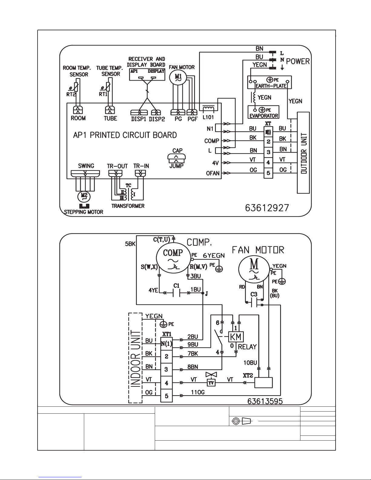
91
Schema elettrico per / Electrical layout for: OGGETTO / OBJECT
MONO SPLIT ON/OFF 7000 W, R410A
MATERIALI / MATERIALS:
DIS:
REV:
SCALA / SCALE:
DATA / DATE: 15.01.2010
DISEGNO \ DRAWING:
INDICE / INDEX:
Disegno proprietà della ditta - a termine di legge è fatto vietato riprodurlo o di renderlo comunque noto a terzi senza autorizzazione
Drawing property of the company - you may not copy, reproduce or transfer it to third parties without authorization
Codice / Code:
N° Pezzi / N. Pieces:
Legenda colori - Colours legend
BK / BLACK / Nero YELLOW/GREEN (YEGN) / Giallo-
Verde
BU / BLUE / Blu RED / ROSSO
GN / GREEN / Verde WH / White / Bianco
OG / ORANGE / Arancione
VT / VIOLET / VIOLA
YE / YELLOW / Giallo
Cablaggi unità interna 7000W / 7000W Indoor unit wiring diagram
Cablaggi unità esterna 7000 W / 7000 W Outdoor unit wiring diagram
3. SCHEMI ELETTRICI / ELECTRIC SCHEMES / ESQUEMAS ELÉCTRICOS / SCHÉMAS ÉLECTRIQUES/ ELEKTRISCHE SCHEMEN

92
3. SCHEMI ELETTRICI / ELECTRIC SCHEMES / ESQUEMAS ELÉCTRICOS / SCHÉMAS ÉLECTRIQUES/ ELEKTRISCHE SCHEMEN
Schema elettrico per / Electrical layout for:
OGGETTO / OBJECT
DUAL SPLIT ON - OFF 2600 W + 2600 W, 410A
MATERIALI / MATERIALS:
DIS:
REV:
SCALA / SCALE:
DATA / DATE: 15.01.2005
DISEGNO \ DRAWING:
INDICE / INDEX:
Disegno proprietà della ditta - a termine di legge è fatto vietato riprodurlo o di renderlo comunque noto a terzi senza autorizzazione
Drawing property of the company - you may not copy, reproduce or transfer it to third parties without authorization
Codice / Code:
N° Pezzi / N. Pieces:
Legenda colori - Colours legend
BLACK / Nero YELLOW/GREEN (Y/G) / Giallo-Verde
BLUE / Blu
GREEN / Verde
ORANGE / Arancione
RED / Rosso
WH / WHITE / Bianco
YELLOW / Giallo
63612591
6361369401
Cablaggi unità interna ON-OFF DUAL 2600 W
2600 W ON-OFF DUAL Indoor unit wiring diagram
Cablaggi unità esterna (2600W + 2600W)
(2600W + 2600W) ON-OFF Outdoor unit wiring diagram

93
Schema elettrico per / Electrical layout for:
OGGETTO / OBJECT
DUAL SPLIT ON - OFF 2600 W + 3500 W, 410A
MATERIALI / MATERIALS:
DIS:
REV:
SCALA / SCALE:
DATA / DATE: 15.01.2005
DISEGNO \ DRAWING:
INDICE / INDEX:
Disegno proprietà della ditta - a termine di legge è fatto vietato riprodurlo o di renderlo comunque noto a terzi senza autorizzazione
Drawing property of the company - you may not copy, reproduce or transfer it to third parties without authorization
Codice / Code:
N° Pezzi / N. Pieces:
Legenda colori - Colours legend
BLACK / Nero YELLOW/GREEN (Y/G) / Giallo-Verde
BLUE / Blu
GREEN / Verde
ORANGE / Arancione
RED / Rosso
WH / WHITE / Bianco
YELLOW / Giallo
63612591
63613694
Cablaggi unità interna ON-OFF DUAL 2600 W, 3500 W
2600 W , 3500 W ON-OFF DUAL Indoor unit wiring diagram
Cablaggi unità esterna (2600 W + 3500 W ) E (3500 W +3500 W)
(2600 W + 3500 W) and (3500 W +3500 W ) ON-OFF Outdoor unit wiring diagram
3. SCHEMI ELETTRICI / ELECTRIC SCHEMES / ESQUEMAS ELÉCTRICOS / SCHÉMAS ÉLECTRIQUES/ ELEKTRISCHE SCHEMEN

94
Schema elettrico per / Electrical layout for:
OGGETTO / OBJECT
MONO SPLIT DC INVERTER 2600 W, 3500 W, 410A
MATERIALI / MATERIALS:
DIS:
REV:
SCALA / SCALE:
DATA / DATE: 15.01.2005
DISEGNO \ DRAWING:
INDICE / INDEX:
Disegno proprietà della ditta - a termine di legge è fatto vietato riprodurlo o di renderlo comunque noto a terzi senza autorizzazione
Drawing property of the company - you may not copy, reproduce or transfer it to third parties without authorization
Codice / Code:
N° Pezzi / N. Pieces:
Legenda colori - Colours legend
BK / BLACK / Nero YELLOW/GREEN (YEGN) / Giallo-
Verde
BU / BLUE / Blu RED / ROSSO
GN / GREEN / Verde WH / White / Bianco
OG / ORANGE / Arancione
VT / VIOLET / VIOLA
YE / YELLOW / Giallo
Cablaggi unità interne DC inverter 2600 W, 3500 W
2600 W, 3500 W DC inverter Indoor units wiring diagram
Cablaggi unità esterne 2600 W, 3500 W DC Inverter
2600W, 3500 W DC inverter Outdoor units wiring diagram
N(1)
XT
3
2
BN
63633494
N
AC-L
PE
U
V
W
TUBE
TEM.SENSOR
RT1
RT2
RT3
CN2
4V
N1
AC-L1
L
FAN
OFAN
COMP.
COMP
AC-N1
PE
M
PE PE
MID.ISOLATION SHEET
ELECTRIC BOX
4YV
AC-N2
AP1
AP2
AC-L
AC-N
L1
L2
E
AC-L3
AC-L2
LX1-2
LX1-1
OVC-COMP
COM-OUT
L1
PE
PE
CN1
CN3
BK
BU
BN
BK
BU
YEGN
YEGN
YEGN
YEGN
YEGN
BN
BN
BN
BU
BU
BU
BU
BU
RD
RD
YE
YE
TEM.SENSOR
OUTROOM
EXHAUST
TEM.SENSOR
T
I
N
U
R
O
O
D
N
I
OUTDOOR UNIT
L3
L2 L2
SAT
RD
W
V
U
EKV
CN1
L4
NOTE:
Motor
applies to the
iron shell motor.
ground only
θ
θ
θ

95
Schema elettrico per / Electrical layout for:
OGGETTO / OBJECT
MONO SPLIT DC INVERTER 5300 W, 7000 W 410A
MATERIALI / MATERIALS:
DIS:
REV:
SCALA / SCALE:
DATA / DATE: 15.01.2005
DISEGNO \ DRAWING:
INDICE / INDEX:
Disegno proprietà della ditta - a termine di legge è fatto vietato riprodurlo o di renderlo comunque noto a terzi senza autorizzazione
Drawing property of the company - you may not copy, reproduce or transfer it to third parties without authorization
Codice / Code:
N° Pezzi / N. Pieces:
Legenda colori - Colours legend
BK / BLACK / Nero YELLOW/GREEN (YEGN) / Giallo-
Verde
BU / BLUE / Blu RED / ROSSO
GN / GREEN / Verde WH / White / Bianco
OG / ORANGE / Arancione
VT / VIOLET / VIOLA
YE / YELLOW / Giallo
AP1: MAI N BOARD
POWER
M1
OUTDOOR UNI T
Cablaggi unità interna DC inverter 5300 W , 7000 W
5300 W, 7000 W DC inverter Indoor unit wiring diagram
Cablaggi unità esterna 5300 W, 7000 W DC Inverter
5300 W, 7000 W DC inverter Outdoor unit wiring diagram
INDC2INDC1
FA
AP1
COMP.
OVC- COMP
OFAN
M1
0
0
0
COM-INNER
N
AC- L
T- SENSOR
3
2
INDOOR UNIT
WARNING
PE
4V

96
English
Key
ROOM TEM. SENSOR
TUBE TEM. SENSOR
POWER
EVAPORATOR
ELECTRIC BOX
STEP MOTOR
FAN MOTOR
INDOOR UNIT
OUTROOM TEM. SENSOR
EXHAUST TEM. SENSOR
OVERHEAT
RT3: TUBE TEM. SENSOR
COMP.
4YV: 4 WAY VALVE
OUTDOOR UNIT:
COOL PLASMA GENERATOR
TRANSFORMER
HEATER (COMP)
DISPLAY
SWING MOTOR
EARTHING PANEL
PIPE-IN TEM.SENSOR
PIPE-MED TEM. SENSOR
PIPE-OUT TEM. SENSOR
ROOM TEM. SENSOR
JUMP
MAIN BOARD
DRIVE BOARD
PFC MODULE
POWER MODULE
FILTER
BASE HEATER
BN: BROWN
BU: BLUE
BK: BLACK
YEGN: YELLOW GREEN
GY: GRAY
WH: WHITE
YE: YELLOW
RD: RED
X: CONNECTER
XT: TERMINAL BOARD
CN: CONNECTOR ON BOARD
L: PHASE
N: NEUTRAL
Italiano
Leggenda
SENSORE TEMP. INTERNA
SENSORE TEMP. EVAP.
ALIMENTAZIONE
EVAPORATORE
SCATOLA COMP. ELETTRICI
MOTORE ALETTE
MOTORE VENTILATORE
UNITA INTERNA
SENSORE TEMP. ESTERNA
SENSORE TEMP. MANDATA
SOVRACCARICO
SENSORE TEMP. TUBO
COMP.: COMPRESSORE
4YV: VALVOLA A 4 VIE
UNITA ESTERNA
GENERATORE PLASMA FREDDA
TRASFORMATORE
RISCALDATORE (COMP)
DISPLAY
MOTORE ALETTE
PANNELLO MESSA A TERRA
PIPE-IN TEM.SENSOR
PIPE-MED TEM. SENSOR
PIPE-OUT TEM. SENSOR
ROOM TEM. SENSOR
CONNETTORE
SCHEDA PRINCIPALE
SCHEDA DRIVE
MODULO PFC
MODULO ALIMENTAZIONE
FILTRO
RISCALDATORE BASAMENTO
BN: MARRONE
BU: BLU
BK: NERO
YEGN: GIALLO VERDE
GY: GRIGIO
WH: BIANCO
YE: GIALLO
RD: ROSSO
X: CONNETTORE
XT: MORSETTIERA
CN: CONNETTORE SU SCHEDA
L: FASE
N: NEUTRO
Español
Legenda
SENSOR TEMP. DEL CUARTO
SENSOR TEMP. DEL TUBO
ALIMENTACIÓN
EVAPORADOR
CAJA ELÉCTRICA
MOTOR PASO A PASO
MOTOR DEL VENTILADOR
UNIDAD INTERNA
SENSOR TEMP. CUARTO EXTERIOR
SENSOR TEMP. DE LA DESCARGA
RECALENTAMIENTO
RT3: SENSOR TEMP. DEL TUBO
COMP.
4YV: VÁLVULA DE 4 VÍAS
UNIDAD EXTERIORA
GENERADOR “COOL PLASMA”
TRANSFORMADOR
CALENTADOR
PANTALLA
MOTOR OSCILLACIÓNES
PANEL PUESTA A TIERRA
SENSOR TUBO EN ENTRADA
SENSOR TUBO MED
SENSOR TUBO EXTERIOR
SENSOR TEMP. DEL CUARTO
SALTAR
FICHA PRINCIPALE
FICHA DE MANDO
MODULO PFC
MODULO DE ALIMENTACIÓN
FILTRE
CALENTADOR BASAMENTO
BN: MARRÓN
BU: AZUL
BK: NIGRO
YEGN: AMARILLO VERDE
GY: GRIS
WH: BLANCO
YE: AMARAILLO
RD: ROJO
X: CONECTOR
XT: PLACA DE BORNES
CN: CONECTOR EN EL APARTO
L: FASE
N: NEUTRAL
Français
Légende
CAPTEUR TEMP. INTERIEURE
CAPTEUR TEMP. ECHANGEUR
ALIMENTATION
EVAPORATEUR
BOITE ELECTRIQUE
MOTEUR POUR VOLETS
MOTEUR VENTILATEUR
UNITA INTERNA
CAPTEUR TEMP. EXTERNE
CAPTEUR TEMP. DECHARGE
SOVRACCARICO
RT3: CAPTEUR TEMP. CHANGEUR
COMP. COMPRESSEUR
4YV: SOUPAPE A 4 VOIES
UNITE EXTERIEURE
COOL PLASMA GENERATOR
TRANSFORMATEUR
RESISTANCE (COMP)
AFFICHEUR
MOTEUR POUR VOLETS
PANNEAU MISE A TERRE
PIPE-IN TEM.SENSOR
PIPE-MED TEM. SENSOR
PIPE-OUT TEM. SENSOR
ROOM TEM. SENSOR
CONNECTEUR
CARTE ELECTRONIQUE PRINCIPALE
CARTE ELECTRONIQUE DRIVE
MODULE PFC
MODULE ALIMENTATION
FILTRE
RESISTANCE CHÂSSIS
BN: MARRON
BU: BLEU
BK: NOIR
YEGN: JAUNE VERT
GY: GRAY
WH: BLANC
YE: JAUNE
RD: ROUGE
X: CONNECTEUR
XT: BORNIER
CN: CONNECTEUR SUR CARTE
L: PHASE
N: NEUTRE
Z EIC HEN ER KL ÄRU NG
INNENTEMPERATUR SENSOR
VERDAMPFUNGTEMPERATUR SENSOR
SPEISUNG
VERDAMPFER
ELEKTRISCHE KOMPONENTEN SCHACHTEL
LAMELLEN MOTOR
LUFTER MOTOR
INNENHEIT
AUßENTEMPERATUR SENSOR
AUSLAßTEMPERATUR SENSOR
ÜBERLADUNG
ROHRTEMPERATUR SENSOR
COMP.: VERDICHTER
4YV: 4 WEGEN VENTIL
AUßENHEIT
KALTESPLASMA GENERATOR
TRANSFORMATOR
HEIZER (COMP)
DISPLAY
LAMELLEN MOTOR
ERDUNG PANEEL
EINTRITTROHR TEMP. SENSOR
MITTELROHR TEMP. SENSOR
AUSTRITTROHR TEMP. SENSOR
RAUMTEMPERATUR SENSOR
VERBINDER
HAUPTKARTE
DRIVEKARTE
PFCMODUL
SPEISUNGMODUL
FILTER
LAGERUNGHEIZER
BN: BRAUN
BU: BLAU
BK: SCHWARZ
YEGN: GELB GRÜN
GY: GRAU
WH: WEIß
YE: GELB
RD: ROT
X: VERBINDER
XT: KLEMMLEISTE
CN: VERBINDER AUF KARTE
L: PHASE
N: UNGELADEN
Deutsch

97
NOTE: ................................................................................................................................................................
.............................................................................................................................................................................
.............................................................................................................................................................................
.............................................................................................................................................................................
.............................................................................................................................................................................
.............................................................................................................................................................................
.............................................................................................................................................................................
.............................................................................................................................................................................
.............................................................................................................................................................................
.............................................................................................................................................................................
.............................................................................................................................................................................
.............................................................................................................................................................................
.............................................................................................................................................................................
.............................................................................................................................................................................
.............................................................................................................................................................................
.............................................................................................................................................................................
.............................................................................................................................................................................
.............................................................................................................................................................................
.............................................................................................................................................................................
.............................................................................................................................................................................
.............................................................................................................................................................................
.............................................................................................................................................................................
.............................................................................................................................................................................
.............................................................................................................................................................................
.............................................................................................................................................................................
.............................................................................................................................................................................
.............................................................................................................................................................................
.............................................................................................................................................................................
.............................................................................................................................................................................
.............................................................................................................................................................................
.............................................................................................................................................................................
.............................................................................................................................................................................
.............................................................................................................................................................................
.............................................................................................................................................................................
.............................................................................................................................................................................
.............................................................................................................................................................................
.............................................................................................................................................................................
.............................................................................................................................................................................
.............................................................................................................................................................................
.............................................................................................................................................................................
.............................................................................................................................................................................
.............................................................................................................................................................................
.............................................................................................................................................................................
.............................................................................................................................................................................
.............................................................................................................................................................................
.............................................................................................................................................................................
.............................................................................................................................................................................
.............................................................................................................................................................................
.............................................................................................................................................................................
.............................................................................................................................................................................
.............................................................................................................................................................................
.............................................................................................................................................................................
.............................................................................................................................................................................

98
NOTE: ................................................................................................................................................................
.............................................................................................................................................................................
.............................................................................................................................................................................
.............................................................................................................................................................................
.............................................................................................................................................................................
.............................................................................................................................................................................
.............................................................................................................................................................................
.............................................................................................................................................................................
.............................................................................................................................................................................
.............................................................................................................................................................................
.............................................................................................................................................................................
.............................................................................................................................................................................
.............................................................................................................................................................................
.............................................................................................................................................................................
.............................................................................................................................................................................
.............................................................................................................................................................................
.............................................................................................................................................................................
.............................................................................................................................................................................
.............................................................................................................................................................................
.............................................................................................................................................................................
.............................................................................................................................................................................
.............................................................................................................................................................................
.............................................................................................................................................................................
.............................................................................................................................................................................
.............................................................................................................................................................................
.............................................................................................................................................................................
.............................................................................................................................................................................
.............................................................................................................................................................................
.............................................................................................................................................................................
.............................................................................................................................................................................
.............................................................................................................................................................................
.............................................................................................................................................................................
.............................................................................................................................................................................
.............................................................................................................................................................................
.............................................................................................................................................................................
.............................................................................................................................................................................
.............................................................................................................................................................................
.............................................................................................................................................................................
.............................................................................................................................................................................
.............................................................................................................................................................................
.............................................................................................................................................................................
.............................................................................................................................................................................
.............................................................................................................................................................................
.............................................................................................................................................................................
.............................................................................................................................................................................
.............................................................................................................................................................................
.............................................................................................................................................................................
.............................................................................................................................................................................
.............................................................................................................................................................................
.............................................................................................................................................................................
.............................................................................................................................................................................
.............................................................................................................................................................................
.............................................................................................................................................................................
 Loading...