

Page 1
TA238A/18-6
PNEUMATIC STAPLER
AGRAFEUSE PNEUMATIQUE
GRAPADORA NEUMATICA
OPERATING and MAINTENANCE MANUAL
MANUEL D'UTILISATION et D'ENTRETIEN
MANUAL DE FUNCIONAMIENTO Y MANTENIMIENTO
WARNING
AVERTISSEMENT
ADVERTENCIA
BEFORE USING THIS TOOL, STUDY THIS MANUAL TO ENSURE SAFETY WARNING AND INSTRUCTIONS.
KEEP THESE INSTRUCTIONS WITH THE TOOL FOR FUTURE REFERENCE.
AVANT D’UTILISER CET OUTIL, LIRE CE MANUEL ET LES CONSIGNES DE SÉCURITÉ AFIN DE
GARANTIR UN FONCTIONNEMENT SÛR.
CONSERVER CE MANUEL EN LIEU SÛR AVEC L’OUTIL AFIN DE POUVOIR LE CONSULTER ULTÉRIEUREMENT.
ANTES DE UTILIZAR ESTA HERRAMIENTA, LEA DETENIDAMENTE ESTE MANUAL PARA FAMILIARIZARSE CON
LAS ADVERTENCIAS E INSTRUCCIONES DE SEGURIDAD.
CONSERVE ESTAS INSTRUCCIONES JUNTO CON LA HERRAMIENTA PARA FUTURAS CONSULTAS.
Page 2

INDEX INDEX ÍNDICE
ENGLISH Page 3 to 10
FRANÇAIS Page 11 to 18
ESPAÑOL Page 19 to 26
DEFINITIONS OF SIGNAL WORDS
WARNING: Indicates a potentially hazardous situation which, if not avoided, could result in
CAUTION: Indicates a potentially hazardous situation which, if not avoided, may result in mi-
NOTE: Emphasizes essential information.
DÉFINITIONS DES DIFFÉRENTS DEGRÉS D’ AVERTISSEMENTS
AVERTISSEMENT: Indique une situation éventuellement dangereuse qui, si elle n’est pas
ATTENTION:
REMARQUE: Souligne des informations importantes.
DEFINICIÓN DE LAS INDICACIONES DE ADVERTENCIA
ADVERTENCIA: Indica una situación potencialmente peligrosa que podría causar la muerte o
PRECAUCIÓN: Indica una situación potencialmente peligrosa que podría causar lesiones menos
NOTA: Resalta informaciones importantes.
death or serious injury.
nor or moderate injury.
contournée, pourrait provoquer la mort ou des blessure sérieuses.
Indique une situation éventuellement dangereuse qui, si elle n’est pas contournée,
pourrait provoquer des blessures légères à moyennement sérieuses.
graves lesiones si no se evita.
graves o leves si no se evita.
2
Page 3
ENGLISH
OPERATING and MAINTENANCE MANUAL
INDEX
1. SAFETY INSTRUCTIONS....................................................................3
2. SPECIFICATIONS AND TECHNICAL DATA......................................6
3. AIR SUPPLY AND CONNECTIONS ....................................................7
4. INSTRUCTIONS FOR OPERATION....................................................7
5. MAINTENANCE .................................................................................10
6. STORAGE..........................................................................................10
7. TROUBLE SHOOTING/REPAIRS .....................................................10
BEFORE USING THIS COMPRESSOR, STUDY THIS MANUAL TO ENSURE SAFETY WARNING
AND INSTRUCTIONS.
WARNING
KEEP THESE INSTRUCTIONS WITH THE TOOL FOR FUTURE REFERENCE.
1. SAFETY INSTRUCTIONS
WARNING
TO AVOID SEVERE PERSONAL INJURY OR PROPERTY
DAMAGE
BEFORE USING THE TOOL, READ CAREFULLY AND UNDERSTAND THE FOLLOWING "SAFETY INSTRUCTIONS". FAILURE TO FOLLOW WARNINGS COULD
RESULT IN DEATH OR SERIOUS INJURY.
PRECAUTIONS ON USING THE TOOL
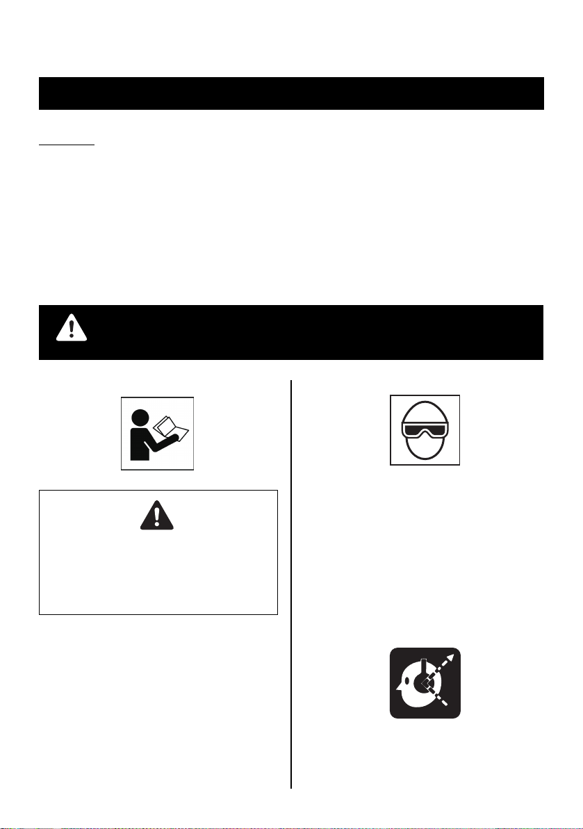
1. WEAR SAFETY GLASSES OR GOGGLES
Danger to the eyes always exists due to the possibility of
dust being blown up by the exhausted air or of a fastener flying up due to the improper handling of the tool. For these
reasons, safety glasses or goggles shall always be worn
when operating the tool.
The employer and/or user must ensure that proper eye protection is worn. Eye protection equipment must conform to
the requirements of Council Directive 89/686/EEC of 21
DEC. 1989 (the American National Standards Institute,
ANSI Z87.1) and provide both frontal and side protection.
The employer is responsible to enforce the use of eye protection equipment by the tool operator and all other personnel in the work area.
NOTE: Non-side shielded spectacles and face shields
alone do not provide adequate protection.
2. EAR PROTECTION MAY BE REQUIRED IN SOME ENVIRONMENTS
As the working condition may include exposure to high noise
levels which can lead to hearing damage, the employer and
user should ensure that any necessary hearing protection is
provided and us ed by the operator and others in the work area.
3
Page 4
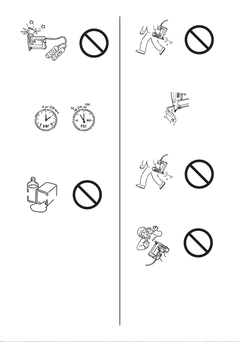
3. DO NOT USE ANY POWER SOURCE EXCEPT AN AIR COMPRESSOR
The tool is designed to operate on compressed air. Do not
operate the tool on any other highpressure gas, combustible gases (e.g., oxygen, acetylene, etc.) since there is the
danger of an explosion. For this reason, absolutely do not
use anything other than an air compressor to operate the
tool.
4. OPERATE WITHIN THE PROPER AIR PRESSURE RANGE
The tool is designed to operate within an air pressure range
of 70 to 100 p.s.i. (5 to 7 bar).
The pressure should be adjusted to the type of the work being fastened. The tool shall never be operated when the operating pressure exceeds 120 p.s.i. (8.3 bar).
Never connect the tool to air pressure which potentially exceeds 200 p.s.i. (13.8 bar) as the tool can burst.
8. DISCONNECT THE AIR SUPPLY AND EMPTY THE MAGAZINE WHEN THE TOOL IS NOT IN USE
Always disconnect the air supply from the tool and empty
the magazine when operation has been completed or suspended, when unattended, moving to a different work area,
adjusting, disassembling, or repairing the tool, and when
clearing a jammed fastener.
9. INSPECT SCREW TIGHTNESS
Loose or improperly installed screws or bolts cause accidents and tool damage when the tool is put into operation.
Inspect to confirm that all screws and bolts are tight and
properly installed prior to operating the tool.
Thinner
5. DO NOT OPERATE THE TOOL NEAR A FLAMMABLE SUBSTANCE
Never operate the tool near a flammable substance (e.g.,
thinner, gasoline, etc.). Volatile fumes from these substances could be drawn into the compressor and compressed together with the air and this could result in an explosion.
6. NEVER USE THE TOOL IN AN EXPLOSIVE ATMOSPHERE
Sparks from the tool may ignite atmospheric gases, dust or
other combustible materials.
7. DO NOT USE A WRONG FITTINGS
The connector on the tool must not hold pressure when air
supply is disconnected. If a wrong fitting is used, the tool
can remain charged with air after disconnecting and thus
will be able to drive a fastener even after the air line is disconnected, possibly causing injury.
Gasoline
10. DO NOT TOUCH THE TRIGGER UNLESS YOU INTEND TO DRIVE A FASTENER
Whenever the air supply is connected to the tool, never
touch the trigger unless you intend to drive a fastener into
the work. It is dangerous to walk around carrying the tool
with the trigger pulled, and this and similar actions should
be avoided.
11. NEVER POINT THE DISCHARGE OUTLET TOWARD YOURSELF AND OTHER PERSONNEL
If the discharge outlet is pointed toward people, serious accidents may be caused when misfiring. Be sure the discharge outlet is not pointed toward people when connecting
and disconnecting the hose, loading and unloading the fasteners or similar operations.
12. USE SPECIFIED FASTENERS (SEE PAGE 6)
The use of fasteners other than specified fasteners will
cause the tool malfunction. Be sure to use only specified
fasteners when operating the tool.
4
Page 5
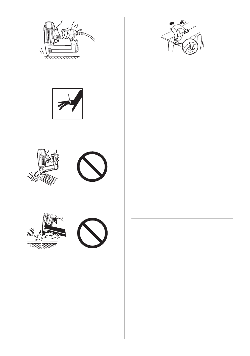
13. PLACE THE DISCHARGE OUTLET ON THE WORK SURFACE PROPERLY
Failure to place the discharge outlet of the nose in a proper
manner can result in a fastener flying up and is extremely
dangerous.
14. KEEP HANDS AND BODY AWAY FROM THE DISCHARGE OUTLET
When loading and using the tool, never place a hand or any
part of body in fastener discharge area of the tool. It is very
dangerous to hit the hands or body by mistake.
15. DO NOT DRIVE FASTENERS CLOSE TO THE EDGE AND CORNER OF THE WORK AND THIN MATERIAL
The workpiece is likely to split and the fastener could fly free
and hit someone.
16. DO NOT DRIVE FASTENERS ON TOP OF OTHER FASTENERS
Driving fasteners on the top of other fasteners may cause
deflection fasteners which could cause injury.
17. REMOVING THE FASTENERS AFTER COMPLETING OPERATION
If fasteners are left in the magazine after the completion of
operation, there is the danger of a serious accident occurring prior to the resumption of operation, should the tool be
handled carelessly, or when connecting the air fitting. For
this reason, always remove all fasteners remaining in the
magazine after completion of the operation.
18. CHECK OPERATION OF THE CONTACT TRIP MECHANISM FREQUENTLY INCASE OF USING A CONTACT
TRIP TYPETOOL
Do not use the tool if the trip is not working correctly as accidental driving of a fastener may result. Do not interfere
with the proper operation of the contact trip mechanism.
19. WHEN USING THE TOOL OUTSIDE OR ELEVATED PLACE
When fastening roofs or similar slanted surface, start fastening at the lower part and gradually work your way up.
Fastening backward is dangerous as you may lose your foot
place.
Secure the hose at a point close to the area you are going
to drive fasteners. Accidents may be caused due to the
hose being pulled inadvertently or getting caught.
20. NEVER USE THE TOOL IF A NY PORTION OF THE TOOL
CONTROLS (e.g., TRIGGER, CONTACT ARM) IS INOPERABLE, DISCONNECTED, ALTERED OR NOT WOKING PROPERLY
21. NEVER ACTUATE THE TOOL INTO FREE SPACE
This will avoid any hazard caused by free flying fasteners
and excessive strain of the tool.
22. ALWAYS ASSUME THAT THE TOOL CONTAINS FASTENERS
23. RESPECT THE TOOL AS A WORKING IMPLEMENT
24. NO HORSEPLAY
25. NEVER LOAD THE TOOL WITH FASTENERS WHEN
ANY ONE OF THE OPERATING CONTROLS (e.g., TRIGGER, CONTACT ARM) IS ACTIVATED
26. WHEN DISPOSING THE MACHINE OR ITS PARTS, FOLLOW THE RELEVANT NATIONAL RULES
OBSERVE THE FOLLOWING GENERAL CAUTION IN ADDITION TO THE OTHER WARNINGS
CONTAINED IN THIS MANUAL
• Do not use the tool as a hammer.
• Always carry the tool by the grip, never carry the
tool by the air hose.
• The tool must be used only for the purpose it was
designed.
• Never remove, t amper with the operating controls
(e.g., TRIGGER, CONTACT ARM)
• Keep the tool in a dry place out of reach of chil-
dren when not in use.
• Do not use the tool without Safety Warning label.
• Do not modify the tool from original design or
function without approval by MAX CO., LTD.
5
Page 6
2. SPECIFICATIONS AND TECHNICAL DATA
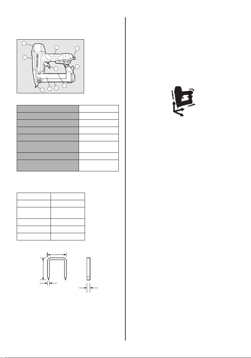
1. NAME OF PARTS
2
7
1
6
9
4
5
10
2. TOOL SPECIFICATIONS
PRODUCT NO. TA238A/18-6
HEIGHT 9-1/2" (241.5mm)
WIDTH 2-1/2" (64mm)
LENGTH 9-1/8" (231mm)
WEIGHT 2.71lbs (1.2kg)
RECOMMENDED OPERATING PRESSURE
LOADING CAPACITY 109staples
AIR CONSUMPTION 0.022ft3(0.61l) at 7 bar
∗ The machine has been compactly designed in order to im-
prove operating weight balance.
3. FASTENER SPECIFICATIONS
PRODUCT NO. TA238A/18-6
CROWN 1/4'' (6.4mm)
LENGTH 1/2''to1-1/2''
WIDTH .05'' (1.25mm)
THICKNESS .044'' (1.12mm)
GAUGE 18
(13 to 38mm)
1 Frame
2 Cylinder Cap
3
3 Exhaust Port
4 Slider Unit
5 Magazine
6 Trigger
8
7 Grip
8 Click Lever
9 Warning Label
(back side)
0 Outlet
70 to 100 p.s.i.
(5 to 7bar)
operating pressure
RECOMMENDED OPERATING PRESSURE:
70 to 100 p.s.i. (5 to 7 bar). Select the operating air pressure within this range for best fastener performance.
DO NOT EXCEED 120 p.s.i. (8.3 bar).
4. TECHNICAL DATA 1 NOISE
A-weighted single-event sound power level
A-weighted single-event emission sound pressure level at
work station
These values are determined and documented in accordance to EN12549 : 1999.
2 VIBRATION
Vibration characteristic value = 2.66 m/s
These values are determined and documented in accordance to ISO 8662-11.
This value is a tool-related characteristic value and does not
represent the influence to the hand-arm-system when using
the tool. An influence to the hand-arm-system when using
the tool will, for example, depend on the gripping force, the
contact pressure forc e, the working direction, the adjustment
of mains supply, the workpiece, the workpiece support.
5. APPLICATIONS
∗ Door and window casings
∗ Plywood, decorative boards, and other interior finish works
∗ Panel assembly and moldings
∗ Sub flooring
∗ Furniture assembly including drawer assembly, case back fas-
tening, blind pinning, and other finishing works
∗ Cabinet assembly
------ LWA, 1s, d 87.2 dB
------- LpA, 1s, d 79.7 dB
2
CROWN
LENGTH
THICKNESS
WIDTH
TOOL AIR FITTINGS:
This tool uses a 1/4"_ P.T. male plug. The inside diameter should
be .28" (7mm) or larger. The fitting must be capable of discharging tool air pressure when disconnected from the air supply.
6
Page 7

3. AIR SUPPLY AND CONNECTIONS
WARNING
[AIR SUPPLY & CONNECTIONS]
Air compressor
Air hose
Used at 70 to 100 p.s.i. (5 to 7 bar)
FITTINGS: Install a male plug on the tool which is free flowing
and which will release air pressure from the tool when disconnected from the supply source.
HOSES: Hose has a min. ID of 1/4" (6 mm) and max. length of
no more than 17' (5 meters).
The supply hose should contain a fitting that will provide "quick
disconnecting" from the male plug on the tool.
SUPPLY SOURCE: Use only clean regulated compressed air as
a power source for the tool.
3-PIECE AIRSET (Air filter, Regulator, Oiler):
Refer to TOOL SPECIFICATIONS for setting the correct operating pressure for the tool.
NOTE:
A filter will help to get the best performance and minimum wear
from the tool because dirt and water in the air supply are major
causes of wear in the tool.
Frequent, but not excessive, lubrication is required for the best
performance. Oil added thru the air line connection will lubricate
the internal parts.
Air filter
Regulator
Oiler
3-piece airset
4. INSTRUCTIONS FOR OPERATION
Read section titled "SAFETY INSTRUCTIONS".
1. BEFORE OPERATION
Check the following prior operation.
1 Wear Safety Glasses or Goggles. 2 Do not connect the air supply. 3 Inspect screw tightness. 4 Check operation of the contact arm & trigger if moving
smoothly.
5 Connect the air supply. 6 Check the air-leakage. (The Tool must not have the air-
leakage.)
7 Hold the Tool with finger-off the trigger, then push the con-
tact arm against the work-piece. (The tool must not operate.)
8 Hold the Tool with contact arm free from work-piece and pull
the trigger. (The Tool must not operate.)
9 Disconnect the air supply.
WARNING
2. OPERATION
Wear safety glasses or goggles. Danger to the eyes always exists due to the possibility of dust being blown up by the exhausted
air or of a fastener flying up due to the improper handling of the
tool. For these reasons, safety glasses or goggles shall always
be worn when operating the tool.
The employer and/or user must ensure that proper eye protection
is worn. Eye protection equipment must conform to the requirements of Council Directive 89/686/EEC of 21 DEC. 1989 (the
American National Standards Institute, ANSI Z87.1) and provide
both frontal and side protection.
The employer is responsible to enforce the use of eye protection
equipment by the tool operator and all other personnel in the work
area.
NOTE: Non-side shielded spectacles and face shields alone do
not provide adequate protection.
WARNING
Keep hands and body away from the discharge outlet when driving the fasteners because of dangerous of hitting the hands or
body by mistake.
7
Page 8
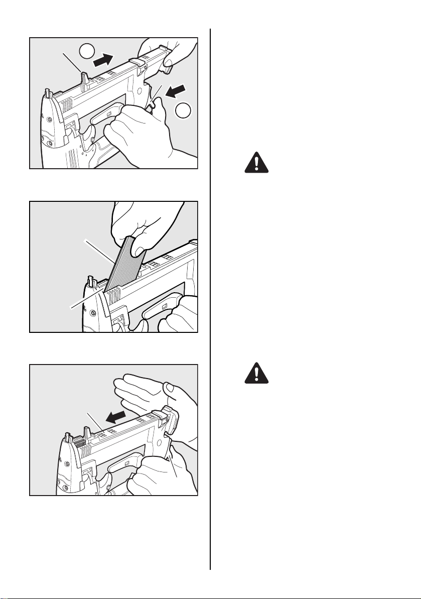
STAPLE LOADING
Slider Unit
TEST OPERATION
1 Adjust the air pressure at 70p.s.i. (5 bar) and connect the air
supply.
2
Click Lever
1
2 Without touching the trigger, depress the contact arm
against the work-piece.
Pull the trigger (The tool must fire the fastener.)
3 With the tool off the work-piece, pull the trigger.
Then depress the connect arm against the work-piece. (The
tool must fire the fastener.)
4 Adjust the air pressure as much as the lowest possible ac-
cording the length of fastener and the hardness of work
piece.
AIR HOSE CONNECTION
Connect the air chuck to the air plug.
1 Push the click lever. 2 Pull out the slider unit.
A set of staples
(Insert it with the square
feet of staples up)
Magazine
3 Insert a set of staples into the magazine with the point of
staples up.
Slider Unit
WARNING
When connecting the air chuck, do not point the staple discharge outlet at any part of your body or at another person,
and do not touch the trigger.
DRIVING FASTENERS
NOTE :
This tool is shipped with SEQUENTIAL TRIP selected.
SEQUENTIAL TRIP
The Sequential Trip requires the operator hold the tool against
the work before pulling the trigger.
This makes accurate fastener placement easier, for instance on
framing, toe nailing and crating applications.
The allows exact fastener location without th e possibility of driving
a second fastener on recall, as described under "Contact Trip".
The Sequential Trip Tool has a positive safely advantage because it will not accidentally drive a fastener if the tool is contacted against the work or anything else-while the operator is holding
the trigger pulled.
Switching SEQUENTIAL TRIP to CONTACT TRIP
WARNING
ALWAYS-disconnect air supply before switching the triggering method.
Click Lever
4 Press the slider unit to set the click lever securely.
8
Page 9
Button
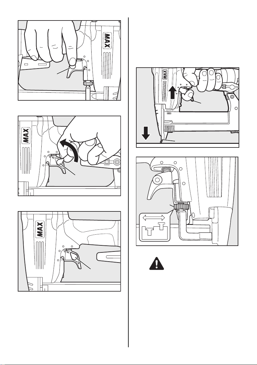
CONTACT TRIP
The common operating procedure on "Contact Trip" tools is for
the operator to contact the work to actuate the trip mechanism
while keeping the trigger pulled, thus driving a fastener each time
the work is contacted.
All pneumatic tools are subject to recoil when driving fasteners.
The tool may bounce, releasing the trip, and if unintentionally allowed to recontact the work surface with the trigger still actuated
(finger still holding trigger pulled) an unwanted second fastener
will be driven.
1 Press the button on the trigger.
Switching lever
2 Turn the switching lever in the direction of the arrow.
Switching lever
3 Set the switching lever as above picture.
Trigger
Contact arm
DRIVING DEPTH ADJUSTIMENT DIAL
Adjustment dial
WARNING
ALWAYS-disconnect air supply before adjusting adjustment
dial.
1 If a Adjustment is required, disconnect air supply. 2 Refer to the figure for direction to turn the dial. 3 Reconnect air supply.
9
Page 10
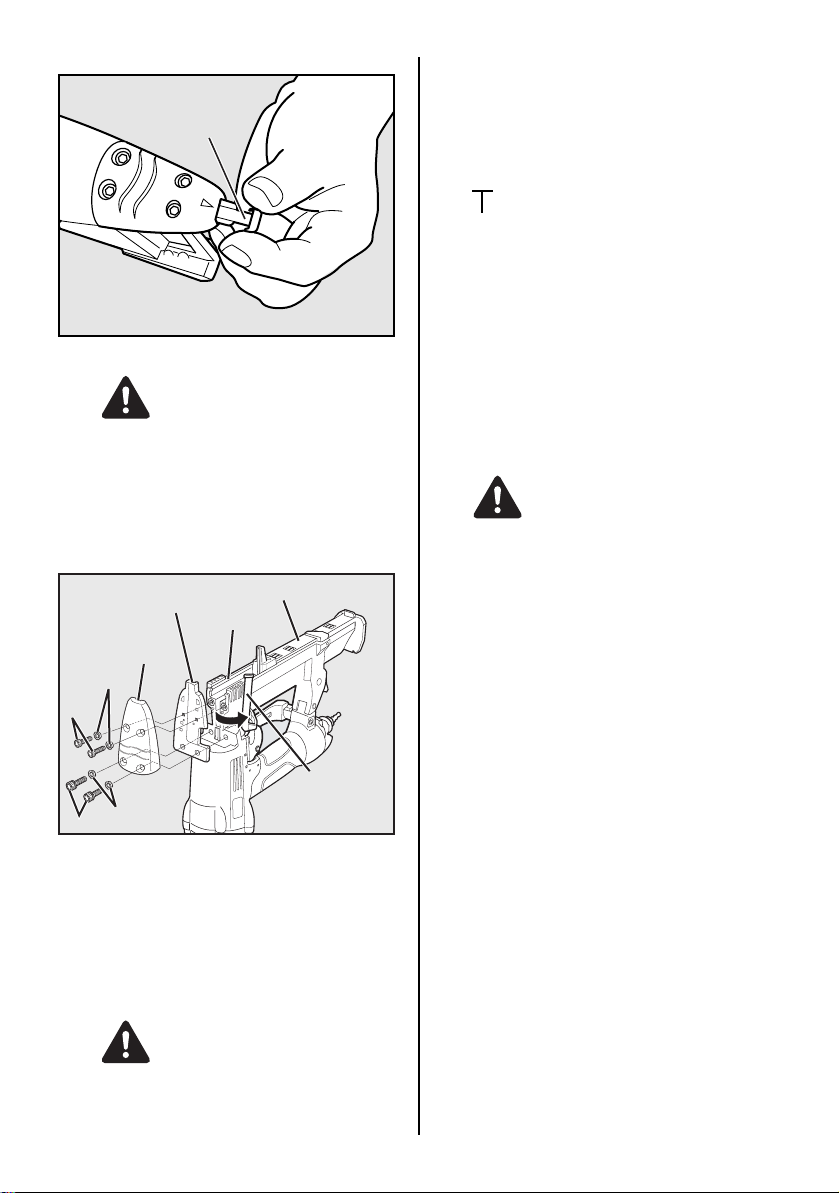
THE CONTACT TIP
Contact tip
WARNING
ALWAYS-disconnect air supply before setting the contact tip.
Set the contact tip on the top of the contact arm, when driving
staples to a soft material.
Use the contact tip at the back of the rear side of the magazine
as necessary.
CLEARING JAMMED STAPLES
Driver guide
Front cover
Collar
Screw
Collar
Screw
1 Disconnect the air hose. 2 Remove the set of staples from the magazine. 3 Take out 4 hexagon socket head cap screws from the mag-
azine.
Then remove the front cover and the driver guide.
4 Clear the staples-jammed inside the driver guide using a
thin iron bar or a flat-blade screw driver. and the ware plate
using a thin iron bar or a flat-blade screwdriver.
5 Reinstall the driver guide and the front cover the set of sta-
ples and bring back the slider unit.
Slider unit
Magagine
Contact arm
5. MAINTENANCE
1 ABOUT PRODUCTION YEAR
This product bears production number at the lower part of
the grip of the main body. The two digits of the number from
left indicates the production year.
(Example)
0 8 8 2 6 0 3 5 D
Year 2008
2 DO NOT FIRE THE STAPLER WHEN IT IS EMPTY 3 USE A 3-PIECE AIRSET
Failure to use a 3-piece airset allows the moisture and dirt
inside compressor to pass into the tool directly. This causes
rust and wear, and results in a poor operating performance.
The hose length between airset and tool should be no longer than 5 m since a longer length results in a reduction in air
pressure.
4 USE RECOMMENDED OIL
The velocite or turbine oil should be used to lubricate the
tool. Upon completion of operations, place 2 or 3 drops of
oil into the air plug inlet with the jet oiler. (Recommended Oil
: ISO VG32)
5 INSPECT AND MAINTAIN DAILY OR BEFORE OPERA-
TION
WARNING
Disconnect air supply and empty the magazine when inspecting or maintaining the tool.
(1) Drain air line filter and compressor
(2) Keep lubricator filled in air 3-pieces set
(3) Clean filter element of air 3-pieces set
(4) Tighten all screws
6. STORAGE
1 When not in use for an extended period, apply a thin coat of
the lubricant to the steel parts to avoid rust.
2 Do not store the tool in a cold weather environment. Keep
the tool in a warm area.
3 When not in use, the tool should be stored in a warm and
dry place. Keep out of reach of children.
4 All quality tools will eventually require servicing or replace-
ment of parts because of wear from the normal use.
7. TROUBLE SHOOTING/REPAIRS
The troubleshooting and/or repairs shall be carried out only by
the MAX CO., LTD. authorised distributors or by other specialists.
WARNING
ALWAYS-disconnect air supply before clearing jammed staples.
10
Page 11

FRANÇAIS
MANUEL D'UTILISATION et D'ENTRETIEN
INDEX
1. CONSIGNES DE SÉCURITÉ .............................................................11
2. CARACTÉRISTIQUES TECHNIQUES ET ACCESSOIRES .............14
3. ALIMENTATION EN AIR COMPRIMÉ ET CONNEXIONS ................15
4. INSTRUCTIONS D’EMPLOI ..............................................................15
5. ENTRETIEN .......................................................................................18
6. STOCKAGE .......................................................................................18
7. DÉPISTAGE DES PANNES/RÉPARATIONS ...................................18
AVANT D'UTILISER CE COMPRESSEUR, LIRE CE MANUEL ET LES CONSIGNES DE SÉCURITÉ
AFIN DE GARANTIR UN FONCTIONNEMENT SÛR.
CONSERVER CE MANUEL EN LIEU SÛR AVEC L'OUTIL AFIN DE POUVOIR LE CONSULTER
AVERTISSEMENT
ULTERIEUREMENT.
1. CONSIGNES DE SÉCURITÉ
AVERTISSEMENT
AFIN D’ÉVITER DES DOMMAGES CORPORELS OU
MATÉRIELS
AVANT D’UTILISER L’OUTIL, LIRE ATTENTIVEMENT CE
MANUEL ET PRENDRE CONNA ISSANCE DES “CONSIGNES
DE SÉCURITÉ” SUIVANTES. LE MANQUEMENT AUX
CONSIGNES DE MISE EN GARDE PEUT ENTRAÎNER LA
MORT OU DES BLESSURES GRAVES.
PRÉCAUTIONS D’EMPLOI DE L’OUTIL
1. PORTEZ DES LUNETTES DE PROTECTION OU DE SÉCURITÉ
Un danger aux yeux est toujours présent en raison de la
poussière rejetée par l’air s’échappant ou de l’éjection de
clous à cause d’une manipulation incorrecte de l’outil. Pour
cette raison il est nécessaire de toujours porter des lunettes
de protection ou de sécurité pendant l'utilisation de l'outil.
L’employeur et/ou l’usager doivent assurer une protection
appropriée des yeux de l'opérateur de l’outil. L’équipement
de protection des yeux doit répondre aux exigences de la
Directive du Conseil 89/686/CEE du 21 décembre 1989
(American National Standards Institute, Norme ANSI Z87.1)
et assurer une protection frontale et latérale de la tête.
L’employeur est responsable pour appliquer le port
d’équipement de protection pour les yeux par l’opérateur de
l’outil et par tous les autres membres du personnel sur le
lieu de travail.
REMARQUE : Les lunettes sans protection latérale ou
frontale n’assurent pas une protection suffisante.
2. DANS CERTAINS ENVIRONNEMENTS UNE PROTECTION AUDITIVE PEUT ÊTRE EXIGÉE
Étant donné que les conditions de travail peuvent entraîner
une exposition à des niveaux de bruit élevés qui peuvent
provoquer des dommages d’audition, l’employeur et
l’utilisateur doivent s’assurer qu’un équipement de protection
auditive est mis à disposition et utilisé par l’opérateur et les
autres personnes se trouvant sur le lieu de travail.
11
Page 12

3. NE PAS UTILISER D’AUTRE SOURCE D’ALIMENTATION QU’UN COMPRESSEUR D’AIR
L’outil est conçu pour fonctionner avec de l’air comprimé.
Ne pas utiliser l’outil avec d’autres gaz sous haute pression,
des gaz combustibles (ex. l’oxygène, l’acétylène, etc.), car
il y a risque d’explosion. Par conséquent, ne rien utiliser
d’autre qu'un compresseur d’air pour faire fonctionner cet
outil.
4. RESPECTER LA PLAGE DE PRESSION D’AIR APPROPRIÉE POUR L’UTILISATION
L'outil est conçu pour fonctionner dans une plage de
pression d'air de 70 à 100 psi (5 à 7 bar).
La pression doit être ajustée au type de pièce à clouer.
L’outil ne doit jamais être utilisé lorsque la pression de
service dépasse 120 psi (8,3 bar).
Ne jamais brancher d’outil sur une alimentation en air
comprimé dont la pression peut éventuellement dépasser
13,8 bars (200 p.s.i.), ce qui peut entraîner l'explosion de
l'outil.
Diluant
5. NE PAS UTILISER L’OUTIL PRÈS D’UNE SUBSTANCE INFLAMMABLE
Ne jamais utiliser l’outil près d’une substance inflammable
(ex. diluant, de l’essence, etc.). Les fumées volatiles de ces
substances peuvent être attirées dans le compresseur,
comprimées en même temps avec l’air, cela risquant de
produire une explosion.
Essence
8. COUPER L’ALIMENTATION EN AIR COMPRIMÉ ET VIDER LE MAGASIN LORSQUE L’OUTIL N’EST PAS UTILISÉ
Veillez à toujours débrancher l’alimentation en air comprimé de
l’outil et à vider le magasin en fin de travail ou lor sque le travail
est suspendu, lorsque l’outil est laissé sans surveillance, est
déplacé vers un au tre lieu de travail, réglé, démo nté ou réparé,
ou encore lorsque vous dégagez un fermoir.
9. CONTRÔLER LE SERRAGE DES VIS
Des vis ou des boulons desserrés ou incorrectement installés
peuvent provoquer des accidents et endommager l’outil lorsqu’il
est mis en service. Contrôler et vérifier que tous les vis et boulons
sont bien serrés et correctement installés avant d’utiliser l’ outil.
10. NE PAS TOUCHER LE DÉCLENCHEUR SAUF POUR ENFONCER UN ÉLÉMENT DE FIXATION
Lorsque l’alimentation en air comprimé est connectée à l’outil, ne
jamais t oucher le déclencheur sauf si dans l’ intention d’enf oncer
un élément de fixation dans la pièce de travail. Il est dangereux
de porter l’outil tout en marchant avec le déclencheur enclen ché.
Ceci, ainsi que des actions similaires doit être évité.
6. N’UTILISEZ JAMAIS L’OUTIL EN PRÉSENCE DE GAZ EXPLOSIFS
Les étincelles de l’outil peuvent enflammer les gaz
atmosphériques, la poussière ou d’autres matériaux
combustibles.
7. NE PAS UTILISER DES PIÈCES DE RACCORDEMENT INADÉQUATES
Le connecteur sur l’outil ne doit pas retenir la pression
lorsque l’alimentation en air comprimé est débranchée. Si
une fixation non appropriée est utilisée, l’outil peut rester
chargé d’air après le débranchement et sera ainsi capable
d’enfoncer un élément de fixation même après le
débranchement de l’arrivée d’air, provoquant ainsi des
dommages éventuels.
11. NE JAMAIS DIRIGER L’ORIFICE DE SORTIE VERS VOUS OU VERS UNE AUTRE PERSONNE
En cas de rat é, les personnes qui se trouveraient dans la t rajectoire
de l’orifice de sortie risquent d’être grièvement blessées. Lorsque
vous branchez ou débranchez le tuyau, chargez ou déchargez les
éléments de fixation ou effectuez une intervention quelconque,
vérifiez toujours que l’orifice de sortie n’est orienté vers personne.
12. UTILISER LES ÉLÉMENTS DE FIXATION APPROPRIÉS (VOIR PAGE 14)
L’utilisation d’éléments de fixation autres que ceux spécifiés
provoque le mauvai s fonctionnement de l’ou til. S’assurer d’ut iliser
uniquement les éléments de fixation appropriés avec l’outil.
12
Page 13

13. PLACER CORRECTEMENT L'ORIFICE DE SORTIE SUR LA SURFACE DE TRAVAIL
Si l’on oublie de placer l'orifice de sortie de façon
appropriée, on risque un détachement violent de l’attache
vers le haut, ce qui est extrêmement dangereux.
14. ÉLOIGNER VOTRE CORPS ET VOS MAINS DE L'ORIFICE DE SORTIE DE L’APPAREIL
Lors du chargement et de l’utilisation de l’outil, ne jamais
placer votre main ou une partie de votre corps dans la zone
de décharge de l’élément de fixation de l’outil. Un contact
accidentel avec les mains ou le corps est très dangereux.
15. NE PAS APPLIQUER LES ÉLÉMENTS DE FIXATION PRÈS DU BORD DE LA PIÈCE ET SUR UN MATÉRIAU MINCE
La pièce de travail peut éclater et l’élément de fixation
risque de sauter et de heurter quelqu’un.
18. VÉRIFIER FRÉQUEMMENT LE FONCTIONNEMENT DU MÉCANISME DE DECLENCHEMENT AU COUP À COUP EN CAS D’UTILISATION D’UN OUTIL DE TYPE À DÉCLENCHEMENT AU COUP À COUP
Ne pas utiliser l’outil si le déclencheur ne fonctionne pas
correctement, car un enfoncement accidentel d’un projectile de
fixation risque de se produire. Ne pas gêner le fonction nement
correct du mécanisme de déclenchement au coup à coup.
19. UTILISATION DE L’OUTIL À L’EXTÉRIEUR OU SUR UN ENDROIT SURÉLEVÉ
Pour fixer un toit, ou une surface inclinée simila ire, commencer
la fixation sur la partie inférieure et exécuter le travail en
montant progressivement. Il est dangereux de faire des
fixations en reculant, car on risque de perdre pied en glissant.
Fixer le tuyau à un point près de la zone où les éléments de
fixation doivent être enfoncés. Des accidents risquent de se
produire à cause d’un tuyau coincé ou tiré par inadvertance.
20. NE JAMAIS UTILISER L’OUTIL SI N’IMPORTE QUELLE PARTIE DES COMMANDES D’OUTIL (PAR EXEMPLE, DÉCLENCHEUR, BRAS DE CONTACT) EST INOPÉRABLE, DÉBRANCHÉE, CHANGÉE OU NE FONCTIONNANT PAS CORRECTEMENT
21. NE JAMAIS ORIENTER L'OUTIL VERS UN ESPACE LIBRE
Les éléments de fixation voltigeant dans l’air présentent un
certain danger, et ceci est néfaste à la durabilité de l'outil.
22. TOUJOURS PRÉSUMER QUE L’OUTIL EST MUNI D'ÉLÉMENTS DE FIXATION
23. CONSIDÉREZ L’OUTIL COMME UN INSTRUMENT DE TRAVAIL
24. NE FAITES PAS DE GESTES BRUSQUES
25. NE JAMAIS MONTER LES FERMOIRS SUR L’OUTIL LORSQU’UNE COMMANDE (DÉTENTE OU BRAS DE CONTACT par exemple) EST ACTIVÉE
26. LORSQUE LA MACHINE OU SES PIÈCES SONT MISES AU REBUT, SUIVEZ LES RÈGLEMENTS NATIONAUX EN VIGUEUR
16. NE PAS ENFONCER DES POINTES OU AGRAFES SUR D’AUTRES ÉLÉMENTS DE FIXATION
Le fait d’enfoncer des éléments de fixation par dessus
d’autres éléments de fixation risque de provoquer un
éclatement de ces éléments qui pourrait provoquer des
blessures.
17. RETRAIT DES ÉLÉMENTS DE FIXATION APRÈS LA FIN DE L’OPÉRATION
Si les éléments de fixation sont laissés dans le magasin
après la fin de l’opération, il y a danger d’accident grave qui
risque de se produire avant la reprise de l’opération, au cas
où l’outil est manipulé négligemment ou lors du
branchement de la fixation d’air. Par conséquent, toujours
enlever tous les éléments de fixation restant dans le
magasin après la fin de l’opération.
RESPECTER LES PRÉCAUTIONS GÉNÉRALES
SUIVANTES EN PLUS DES AUTRES
AVERTISSEMENTS DÉCRITS DANS CE MANUEL
• Ne pas utiliser l’outil comme un marteau.
• Saisissez toujours l’outil par la poignée, et ne le
transportez jamais en le tenant par le tuyau d’air.
• L’outil doit être utilisé uniquement pour l’usage
préconisé.
• Ne jamais retirer ou altérer les commandes
(DÉTENTE OU BRAS DE CONTACT par exemple).
• Conserver l’outil dans un endroit sec, hors de
portée des enfants, lorsqu’il n’est pas utilisé.
• Ne pas utiliser l’outil sans l’étiquette de sécurité.
• Ne pas modifier la conception originale ou les
caractéristiques de l’outil sans le consentement
de MAX CO. LTD.
13
Page 14

2. CARACTÉRISTIQUES TECHNIQUES ET ACCESSOIRES
1. NOM DES PIÈCES
2
7
1
6
9
4
5
10
2. CARACTÉRISTIQUES DE L’OUTIL
N° DE PRODUIT TA238A/18-6
HAUTEUR 9-1/2" (241,5mm)
LARGEUR 2-1/2" (64mm)
LONGUEUR 9-1/8" (231mm)
POIDS 2,71 lbs (1,2 kg)
PRESSION DE SERVICE
RECOMMANDÉE
CAPACITÉ DE CHARGE 109 agrafes
CONSOMMATION EN AIR
COMPRIMÉ
∗ La machine a été conçue pour être compacte afin d'améliorer
la répartition du poids en charge.
3. CARACTÉRISTIQUES DU MATÉRIEL DE FIXATION
N° DE PRODUIT TA238A/18-6
COURONNE 1/4'' (6,4 mm)
LONGUEUR 1/2'' à 1-1/2''
LARGEUR 0,05'' (1,25 mm)
ÉPAISSEUR 0,044'' (1,12 mm)
CALIBRE 18
(13 à 38 mm)
1 Boîtier
2 Couvercle de
3
cylindre
3
Orifice d'évacuation
4
Système à coulisse
5 Magasin
8
6 Déclencheur
7 Poignée
8 Levier à cliquet
9 Étiquette
d'avertissement (à
l'arrière)
0 Orifice de sortie
70 à 100 psi
(5 à 7 bar)
0,022 pi3(0,61 l) à 7 bar
pression de service
PRESSION DE SERVICE RECOMMANDÉE :
70 à 100 psi (5 à 7 bar). Régler l’air comprimé à l’intérieur de cette
plage pour garantir la meilleure performance possible de fixation.
NE PAS DÉPASSER 120 psi (8,3 bar).
4. CARACTÉRISTIQUES TECHNIQUES 1 BRUIT
Niveau de puiss ance sonore pulsée par rapport à la courbe A
Niveau de pression acoustique pulsée par rapport à la
courbe A
------------- LpA, 1s, d 79,7 dB au poste de travail
Ces valeurs out été calculées et documentées,
conformément à la norme EN12549 :1999.
2 VIBRATIONS
Valeur caractéristique des vibrations = 2,66 m/s
Ces valeurs out été calculées et documentées,
conformément à la norme ISO 8662-11.
Cette valeur est une valeur caractéristique associée à un
outil et n'ind ique pas l'effet sur le système main-bras lorsque
l'outil est utilisé. L'effet sur le système main-bras lorsque
l'outil est utilisé dépendra, par exemple, de la force de saisie,
de la force de la pression de contact, du sens de travail, du
réglage de l'alimentation secteur, de la pièce à travailler et de
son support.
5. APPLICATIONS
∗ Montage de châssis de portes et de fenêtres
∗ Fixation de panneaux décoratifs en contreplaqué ou autres
travaux d’aménagement intérieur
∗ Montage de panneaux et de pièces moulées
∗ Faux plancher
∗ Assemblage de meubles et de tiroirs y cinorus de tiroirs,
fixation de parois arrière de placards, fixation cachée et autres
travaux de finition
∗ Assemblage de placards et armoires
------------ LWA, 1s, d 87,2 dB
2
COURO
LONGUEUR
ÉPAISSEUR
LARGEUR
PIÈCES DE RACCORDEMENT D’AIR
COMPRIMÉ DE L'OUTIL :
Cet outil est équipé d’une prise mâle avec filet extérieur de 1/4"
(6 mm)s. Le diamètre intérieur devrait être de 0,28" (7 mm)
minimum. Le raccord doit permettre de décharger l’air comprimé
de l’outil lorsque l’alimentation en air comprimé est interrompue.
14
Page 15

3. ALIMENTATION EN AIR COMPRIMÉ ET CONNEXIONS
AVERTISSEMENT
[ALIMENTATION EN AIR COMPRIMÉ ET CONNEXIONS]
Compresseur d’air
Tuyau à air
Pression 70 à 100 psi (5 à 7 bar)
PIÈCES DE RACCORDEMENT : Installer un raccord mâle à flux
libre sur l’outil qui relâche la pression d’air de l’outil lorsqu’il est
débranché de la source d’alimentation.
TUYAUX : Le diamètre intérieur du tuyau doit être de 1/4" (6 mm)
minimum et d’une longueur maximale de 17" (5 mètres).
Le tuyau d’alimentation doit avoir une fixation qui assure un
“débranchement rapide” de la fiche mâle sur l’outil.
SOURCE D’ALIMENTATION : Utiliser uniquement l’air
comprimé régulé comme source d’alimentation pour l’outil.
UNITÉ D'AIR COMPRIMÉ À TROIS ÉLÉMENTS (Filtre à air,
régulateur, graisseur) :
Se référer aux SPECIFICATIONS DE L’OUTIL pour le réglage de
la pression de fonctionnement appropriée pour l’outil.
REMARQUE :
Un filtre assure une meilleure performance et un minimum d’usure
de l’outil, parc e que l’encrassement et l’eau dans l ’alimentation en
air comprimé sont les sources principales d’usure de l’outil.
Des graissages fréquents, mais non excessifs sont nécessaires
pour conserver la meilleure performance. L’huile ajoutée à
travers le raccord de ligne d’air lubrifie les pièces internes.
Régulateur
Filtre a air
Unité d'air comprimé à trois
éléments
Graisseur
4. INSTRUCTIONS D’EMPLOI
Lire le paragraphe intitulé “CONSIGNES DE
SÉCURITÉ”.
1. AVANT CHAQUE UTILISATION
Vérifier les points suivants avant d’utiliser l’outil.
1 Porter des lunettes de protection ou de sécurité. 2 Ne pas encore brancher l’alimentation en air comprimé. 3 Vérifier le serrage des vis. 4 Vérifier le fonctionnement de la barre de contact et
s’assurer que le levier de commande se déplace librement.
5 Brancher l’alimentation en air comprimé. 6 Rechercher une éventuelle présence d’une fuite d’air.
(L’outil ne doit pas présenter de fuite d’air.)
7 Tenir l’outil (ne pas mettre de doigt sur le levier de
commande) et appuyer la barre de contact contre la pièce
à fixer. (L’outil ne doit pas fonctionner.)
8 Tenir l’outil en sorte que la barre de contact ne repose pas
sur la pièce à fixer et appuyer sur le levier de commande.
(L’outil ne doit pas fonctionner.)
9 Débrancher l'alimentation en air comprimé.
AVERTISSEMENT
2. PENDANT L'UTILISATION
Porter des lunettes de protection ou de sécurité. Un danger aux
yeux est toujours présent en raison de la poussière rejetée par
l’air s’échappant ou de l’éjection de clous à cause d’une
manipulation incorrecte de l’outil. Pour cette raison il est
nécessaire de toujours porter des lunettes de protection ou de
sécurité pendant l'utilisation de l'outil.
L’employeur et/ou l’usager doivent assurer une protection
appropriée des yeux de l'opérateur de l’outil. L’équipement de
protection des yeux doit répondre aux exigences de la Directive
du Conseil 89/686/CEE du 21 décembre 1989 (American
National Standards Institute, Norme ANSI Z87.1) et assurer une
protection frontale et latérale de la tête.
L’employeur est responsable pour appliquer le port d’équipement
de protection pour les yeux par l’opérateur de l’outil et par tous
les autres membres du personnel sur le lieu de travail.
REMARQUE : Les lunettes sans protection latérale ou frontale
n’assurent pas une protection suffisante.
AVERTISSEMENT
Veiller à tenir les mains et le reste du corps hors de portée de
l’orifice de sortie pendant l'enfoncement des éléments de fixation
pour éviter de toucher accidentellement les mains ou le corps.
15
Page 16

CHARGEMENT DES AGRAFES
Système à
coulisse
2
Levier à cliquet
1
1 Pousser le levier à cliquet. 2 Extraire le système à coulisse.
Ensemble d'agrafes
(L'insérer avec le pied carré
des agrafes vers le haut)
Magasin
3 Insérer un ensemble d'agrafes dans le magasin avec les
extrémités pointues des agrafes vers le haut.
TEST
1 Régler l’air comprimé sur 70 psi (5 bar) et brancher
l’alimentation en air comprimé.
2 Appuyer la barre de contact contre la pièce à fixer sans
cependant toucher au levier de commande.
Tirer le déclencheur (L’outil doit tirer la pointe.)
3 Appuyer sur le levier de commande, l’outil ne devant pas
toucher la pièce à fixer.
Appuyer ensuite la barre de contact contre la pièce à fixer.
(L’outil doit tirer la pointe.)
4 Régler la pression de l'air comprimé à un niveau aussi bas
que possible, selon la longueur de l'attache et la dureté de
la pièce de travail.
RACCORDEMENT DU TUYAU D'AIR
Raccorder le mandrin à air au raccord pneumatique.
AVERTISSEMENT
Lors du raccordement du mandrin à air, ne pas pointer
l'orifice de sortie des agrafes vers une quelconque partie du
corps ou une autre personne et ne pas toucher le
déclencheur.
ENFONCEMENT D'ÉLÉMENTS DE FIXATION
REMARQUE :
Cet outil est livré avec le DÉCLENCHEMENT SÉQUENTIEL
sélectionné.
DECLENCHEMENT DE TIR SEQUENTIEL
Il faut, pour le déclenchement séquentiel, que l’appareil touche
l’ouvrage avant que l’on ne déclenche le levier de commande.
Cette technique facilite le placement précis de la pointe/l'agrafe,
par exemple dans les applications d'encadrement, de clouage en
biais et de mise en caisse.
Cette technique permet de positionner la pointe/l’agrafe avec
précision sans risquer que le recul ne libère une 2e pointe/agrafe.
Les appareils à déclenchement séquentiel présentent les
avantages suivants en matière de sécurité: il n’y a aucun
déclenchement accidentel si l’appareil entre en contact avec
l’ouvrage ou autre objet lorsque l’on appuie sur le levier de
commande.
Commutation du DÉCLENCHEMENT SÉQUENTIEL en
DÉCLENCHEMENT PAR CONTACT
Système à coulisse
Levier à
cliquet
4 Appuyer sur le système à coulisse afin que le levier à cliquet
soit bien positionné.
AVERTISSEMENT
TOUJOURS couper l'alimentation en air avant de commuter la
méthode de déclenchement.
16
Page 17

Bouton
DECLENCHEMENT PAR CONTACT
Le fonctionnement normal des appareils avec déclenchement
par contact prévoit que l’opérateur touche l’ouvrage avec
l’appareil pour déclencher un tir tout en maintenant le levier de
commande appuyeé.
Tous les outils pneumatiques de tir d’attaches sont sujets à un
recul. L’appareil peut, éventuellement, actionner le
déclenchement par contact lors d’un éventuel impact; si cela
entraîne un nouveau contact accidentel de l’appareil avec la
surface à fixer alors que le levier de commande est encore
appuyé, un deuxième tir sera déclenché involontairement.
1 Appuyer sur le bouton du déclencheur.
Levier de commutation
2 Tourner le levier de commutation dans le sens de la flèche.
Levier de commutation
3 Régler le levier de commutation tel que sur l'image ci-
dessus.
Déclencheur
Bras de contact
DISQUE DE REGLAGE EN PROFONDEUR DES POINTES
Cadran d e réglage
AVERTISSEMENT
TOUJOURS couper l’alimentation en air comprimé avant de
tourner le disque de réglage.
1 Si oui, couper l’alimentation en air comprimé. 2 Le repère placé sur la barre de contact indique le sens dans
lequel il faut tourner le disque de réglage.
3 Rebrancher l’alimentation en air comprimé.
17
Page 18

CAPUCHON DE CONTACT
Bout de contact
AVERTISSEMENT
TOUJOURS couper l’alimentation en air comprimé avant de
mettre le capuchon de contact.
Ce dernier se place sur la pointe de la barre de contact si le
matériel à fixer est souple.
Utiliser si nécessaire le capuchon de contact situé à l'arrière du
magasin.
RETRAIT DES AGRAFES COINCÉES
Guide d’entraînement
Capot avant
Collier
Vis
Coulisseau de magasin
Magasin
5. ENTRETIEN
1 À PROPOS DE L’ANNÉE DE PRODUCTION
Ce produit porte le numéro de production à la partie
inférieure de l a poignée du corps principal. Le s deux chiffres
du numéro de la gauche indiquent l’année de production.
(Exemple)
0 8 8 2 6 0 3 5 D
Année 2008
2 NE PAS DÉCLENCER L’AGRAFEUSE QUAND ELLE
EST VIDE
3 UTILISER UNE UNITÉ D'AIR COMPRIMÉ À TROIS
ÉLÉMENTS
Le fait de ne pas utiliser une unité d'air comprimé à trois
éléments permet l’entrée de l’humidité et de saletés à
l’intérieur du compresseur qui passe directement dans
l'outil. Cela crée une formation de rouille et provoque l’usure
conduisant à une mauvaise performance pendant
l’utilisation. La longueur du tuyau entre le régulateur et l'outil
ne doit pas dépasser 5 m, étant donné qu’une longueur
supérieure réduit la pression d’air.
4 UTILISER UNE HUILE RECOMMANDÉE
L’huile de turbine fluide doit être utilisée pour lubrifier l'outil.
Après la fin des opérations, placer 2 ou 3 gouttes d’huile
dans l’entrée d’air avec le graisseur à jet. (Huile
recommandée : ISO VG32)
5 VÉRIFIER ET ENTRETENIR L’OUTIL TOUS LES JOURS
OU AVANT CHAQUE UTILISATION
AVERTISSEMENT
Couper l’alimentation en air comprimé et vider le magasin
avant toute vérification ou mesure d’entretien de l’outil.
(1) Vider le filtre de la conduite d’air et le compresseur
(2) Veiller à ce que le graisseur soit toujours plein dans l’unité
d’air comprimé à trois éléments
(3) Nettoyer l’élément filtrant de l’unité d’air comprimé à trois
éléments
(4) Bien serrer toutes les vis
Bras de
Collier
Vis
1 Débrancher le tuyau d'air. 2 Retirer le jeu d'agrafes du magasin. 3 Extraire les 4 vis à six pans creux du magasin.
Retirer ensuite le capot avant et le guide d'entraînement.
4 Retirer les agrafes coincées à l'intérieur du guide
d'entraînement et la plaque d'usure à l'aide d'une tige de fer
ou d'un tournevis plat.
5
Réinstaller le gui de d'entraînement, le capot avant, l'ensemble d'agrafes et ramener en arrière le système à coulisse.
contact
AVERTISSEMENT
TOUJOURS débrancher l'alimentation en air comprimé avant
de retirer les agrafes coincées.
6. STOCKAGE
1 Si l’outil doit rester inutilisé pendant un certain temps,
appliquer une mince couche de lubrifiant sur les pièces en
acier pour éviter l’apparition de rouille.
2 Ne pas entreposer l’outil dans un endroit exposé au froid.
Le conserver dans un endroit chaud.
3 Si l’outil reste inutilisé, il faut le conserver dans un endroit
chaud et sec. Le conserver hors de portée des enfants.
4 Même les outils de qualité peuvent éventuellement
nécessiter des mesures d’entretien ou le remplacement de
pièces en raison de l’usure normale.
7. DÉPISTAGE DES PANNES/ RÉPARATIONS
Le dépistage de pannes et/ou les réparations ne doivent être
réalisés que par des distributeurs autorisés de la société MAX
CO.,LTD. ou tout autre spécialiste qui respectera les
informations contenues ici.
18
Page 19

ESPAÑOL
MANUAL DE FUNCIONAMIENTO Y MANTENIMIENTO
ÍNDICE
1. INSTRUCCIONES DE SEGURIDAD .................................................19
2. ESPECIFICACIONES Y DATOS TÉCNICOS....................................22
3. SUMINISTRO DE AIRE COMPRIMIDO Y CONEXIONES ................23
4. INSTRUCCIONES DE FUNCIONAMIENTO......................................23
5. MANTENIMIENTO .............................................................................26
6. ALMACENAMIENTO .........................................................................26
7. LOCALIZACIÓN DE AVERÍAS/REPARACIONES............................26
ANTES DE UTILIZAR ESTA HERRAMIENTA, LEA DETENIDAMENTE ESTE MANUAL PARA
FAMILIARIZARSE CON LAS ADVERTENCIAS E INSTRUCCIONES DE SEGURIDAD.
ADVERTENCIA
CONSERVE ESTAS INSTRUCCIONES JUNTO CON LA HERRAMIENTA PARA FUTURAS
CONSULTAS.
1. INSTRUCCIONES DE SEGURIDAD
ADVERTENCIA
PARA EVITAR GRAVES DAÑOS PERSONALES O A LA
PROPIEDAD
ANTES DE UTILIZAR LA HERRAMIENTA, LEA CON
ATENCIÓN, COMPRENDA Y FAMILIARÍCESE CON LAS
SIGUIENTES INSTRUCCIONES DE SEGURIDAD. EL
INCUMPLIMIENTO DE LAS ADVERTENCIAS
SIGUIENTES PUEDE PROVOCAR LESIONES GRAVES E
INCLUSO LA MUERTE.
PRECAUCIONES AL UTILIZAR LA HERRAMIENTA
1. LLEVE GAFAS PROTECTORAS O DE SEGURIDAD
La zona de los ojos se encuentra siempre bajo peligro
potencial debido a la presencia de polvo en el aire
expulsado o a la posibilidad de que una grapa o un clavo
salgan despedidos si se manipula la herramienta de
manera incorrecta. Por ese motivo, es necesario utilizar
siempre gafas protectoras o de seguridad al utilizar la
herramienta.
El encargado y/o el usuario deben asegurarse de llevar
protección ocular apropiada. El equipo de protección ocular
debe responder a las exigencias de la Directiva del Consejo
89/686/CEE del 21 de diciembre de 1989 (Instituto
Nacional Americano de Normalización, ANSI Z87.1) y
asegurar una protección tanto frontal como lateral.
El encargado es responsable de imponer el uso de
equipamiento de protección ocular al operador de la
herramienta, así como al resto de los trabajadores en la
zona de trabajo.
NOTA:
Las gafas sin protección lateral y las pantallas
únicamente frontales no aseguran una protección adecuada.
2. EN ALGUNAS CIRCUNSTANCIAS PUEDE SER
NECESARIO UTILIZAR PROTECCIÓN DE OÍDOS
El usuario puede estar expuesto a un nivel elevado de
ruido, que puede causar daños al oído. El encargado y/o
usuario deben asegurarse de utilizar la protección
necesaria y de que el resto de los trabajadores la utilicen en
la zona de trabajo.
19
Page 20

3. NO UTILICE NINGUNA FUENTE DE ENERGÍA EXCEPTO UN COMPRESOR DE AIRE
La herramienta está diseñada para funcionar con aire
comprimido. No utilice la herramienta con ningún otro gas
de alta presión, gases combustibles (por ejemplo, oxígeno,
acetileno, etc.) ya que existe el peligro de explosión. Por
esta razón, es imprescindible utilizar únicamente un
compresor de aire para el funcionamiento de la
herramienta.
8. MIENTRAS LA HERRAMIENTA NO ESTÉ EN USO, DESCONECTE EL SUMINI STRO DE AIRE COMPRIMIDO Y VACÍE EL CARTUCHO
Desconecte siempre el suministro de aire comprimido
desde la herramienta y vacíe el cartucho cuando se ha
completado o interrumpido la operación, cuando
permanece sin supervisión, cuando se traslada a una zona
de trabajo diferente, cuando se ajusta, desmonta o repara
la herramienta, así como cuando se desatasca una grapa.
4. UTILICE DENTRO DEL LÍMITE DE PRESIÓN DE AIRE ADECUADO
La herramienta esta designada para funcionar dentro de
limite de presión de aire de 70 a 100 p.s.i. (5 a 7 bares).
La presión debería adaptarse dependiendo de la clase de
trabajo. Nunca debe utilizarse la herramienta cuando la
presión de funcionamiento sea superior a 120 p.s.i. (8,3
bares).
Nunca conecte la herramienta a una alimentación de aire
comprimido cuya presión pueda superar los 200 p.s.i. (13,8
bares) porque podría reventar.
Diluyente
5. NO UTILICE LA HERRAMIENTA CERCA DE SUSTANCIAS INFLAMABLES
Nunca utilice la herramienta cerca de sustancias
inflamables (por ejemplo diluyente, gasolina, etc.). Los
gases volátiles de estas sustancias podrían ser
comprimidos junto con el aire dentro del compresor
pudiendo provocar una explosión.
6. NUNCA UTILICE LA HERRAMIENTA EN UN AMBIENTE EXPLOSIVO
Las chispas de la herramienta pueden inflamar gases
atmosféricos, polvo u otros materiales combustibles.
7. NO UTILICE ACCESORIOS INADECUADOS
El conector de la herramienta no debe contener presión
cuando el suministro de aire comprimido esté
desconectado. Si se utiliza un accesorio inadecuado, la
herramienta puede permanecer cargada con aire tras
desconectarla y, por lo tanto, puede continuar funcionando
incluso tras haber desconectado el suministro de aire
comprimido y causar daños.
Gasolina
9. COMPRUEBE LA TENSIÓN DE LOS TORNILLOS
Los tornillos flojos o mal instalados pueden causar
accidentes y daños a la herramienta durante el uso.
Compruebe que todos los tornillos estén apretados y bien
instalados antes de utilizar la herramienta.
10. NO TOQUE EL GATILLO A MENOS QUE TENGA INTENCIÓN DE UTILIZARLO
Cuando el suministro de aire comprimido esté conectado a la
herramienta, nunca toque el gatillo a menos que tenga intención
de utilizarlo. Es peligroso llevar la herramienta con el gatillo
apretado; esta acción y cualquier otra semejante deben evitarse.
11. NUNCA APUNTE LA SALIDA DE DESCARGA HACIA USTED U OTRAS PERSONAS
Si la salida de descarga apunta a personas pueden
ocasionarse serios accidentes en caso de disparo
accidental. Asegúrese de que la salida de descarga no esté
apuntada hacia ninguna persona cuando conecte y
desconecte la manguera, cargue y descargue las grapas o
realice operaciones similares.
20
Page 21

12. UTILICE GRAPAS ESPECÍFICAS (VÉASE PÁGINA 22)
El uso de grapas que no sean las específicas puede causar
el funcionamiento incorrecto de la herramienta. Asegúrese
de utilizar únicamente grapas específicas.
18. COMPROBAR LA OPERACIÓN MECANISMO DE CONTACTO CON FRECUENCIA EN CASO DE UTILIZAR UNA HERRAMIENTA DE TIPO “TRIP” CONTACTO
No utilizar la herramienta si “trip” no funciona
correctamente, ya que puede grapar sin querer. No tocar la
operación propia del mecanismo “trip” contacto.
13. COLOQUE LA SALIDA DE DESCARGA SOBRE LA SUPERFICIE DE TRABAJO DEL MODO CORRECTO
Si se olvida de poner la salida de descarga situada en la
punta del cargador de la manera correcta, se puede
provocar que una grapa salga disparada hacia arriba y esto
es extremadamente peligroso.
14. MANTENGA LAS MANOS Y EL CUERPO ALEJADOS DE LA SALIDA DE DESCARGA
Al cargar y usar la herramienta no coloque ni la mano ni
ninguna parte del cuerpo sobre la salida de descarga, ya
que puede resultar muy peligroso. Es muy peligroso
golpear las manos o el cuerpo por error.
15. NO GRAPE JUNTO AL BORDE DE SUPERFICIES O MATERIALES FINOS
Es probable que la superficie se parta o desgarre y la grapa
podría saltar y dañar a alguien.
16. NO GRAPE SOBRE OTRAS GRAPAS
Grapar sobre otras grapas puede causar desvío que, a su
vez, podría causar daños.
17. QUITE LAS GRAPAS DESPUÉS DE COMPLETAR LA OPERACIÓN
Si se dejan las grapas puestas tras completar la operación,
existe el peligro de un accidente grave si se maneja la
herramienta de forma descuidada o al conectar la válvula de
aire. Por este motivo es imprescindible quitar todas las grapas
que queden en el cartucho tras completar la operación.
19. UTILIZACIÓN DE LA HERRAMIENTA AL AIRE LIBRE O EN SITIOS ELEVADOS
A la hora de grapar tejados u otras superficies inclinadas,
empiece en la parte inferior y suba poco a poco. Grapar
hacia atrás es peligroso ya que se puede resbalar.
Asegure la manguera cerca de la zona donde se va a
grapar. Se pueden provocar accidentes si se tira de la
manguera de modo fortuito o si se engancha.
20. NUNCA UTILICE LA HERRAMIENTA SI CUALQUIER PORCIÓN DE LOS CONTROLES DE L A HERRAMIENTA (POR EJEMPLO, DISPARADOR, BRAZO DE CONTACTO) ES INOPERABLE, DESCONECTADA, ALTERADA O NO OPERA CORRECTAMENTE
21. NUNCA DISPARE AL AIRE
Esto evitará todo peligro causado por grapas que pueden
salir disparadas así como un sobreesfuerzo innecesario de
la herramienta.
22. SIEMPRE SE DEBE ASUMIR QUE LA HERRAMIENTA CONTIENE GRAPAS
23. DEBE RESPETAR LA HERRAMIENTA COMO UN IMPLEMENTO DE TRABAJO
24. NO JUEGUE HACIENDO BROMAS
25. NUNCA CARGUE LA HERRAMIENTA CON LOS AFIANZADORES CUANDO CUALQUIERA DE LOS CONTROLES DE OPERACIÓN (ej.: DISPARADOR, BRAZO DE CONTACTO) SE ENCUENTRA ACTIVADO
26. CUANDO SE DESECHEN LA MÁQUINA O SUS PIEZAS, DEBEN SEGUIRSE LAS NORMATIVAS NACIONALES PERTINENTES
OBSERVE LAS PRECAUCIONES SIGUIENTES
JUNTO CON EL RESTO DE ADVERTENCIAS
INCLUIDAS EN ESTE MANUAL
• No utilice la herramienta como martillo.
• Agarre siempre la herramienta por el mango y
nunca la sujete por los tubos de aire.
• La herramie nta debe utilizarse únicamente para el
propósito para el que fue designada.
• Nunca retire, fuerce los controles de operación
(ej.: DISPARADOR, BRAZO DE CONTACTO)
• Cuando la herramienta no se esté utilizando,
guárdela en un lugar seco fuera del alcance de
los niños.
• No utilice la herramienta sin la etiqueta de
Advertencia de seguridad.
• No modifique el diseño original ni la función de la
herramienta sin la aprobación de MAX CO., LTD.
21
Page 22

2. ESPECIFICACIONES Y DATOS TÉCNICOS
1. DENOMINACIÓN DE LAS PIEZAS
2
7
1
6
9
4
5
10
2. ESPECIFICACIONES DE LA HERRAMIENTA
N° DE PRODUCTO TA238A/18-6
ALTURA 9-1/2" (241,5mm)
ANCHURA 2-1/2" (64mm)
LONGITUD 9-1/8" (231mm)
PESO 2,71lbs (1,2kg)
PRESIÓN DE FUNCIONAMIENTO
RECOMENDADA
CAPACIDAD DE CARGA 109 grapas
CONSUMO DE AIRE 0,022ft3(0,61l) a 7 bares
∗ La herramienta tiene un diseño compacto para mejorar el
equilibrio durante el funcionamiento.
3. ESPECIFICACIONES DE LAS GRAPAS
N° DE PRODUCTO TA238A/18-6
CORONA 1/4" (6,4mm)
LONGITUD 1/2'' a 1-1/2''
ANCHURA 0,05'' (1,25mm)
ESPESOR 0,044'' (1,12mm)
CALIBRE 18
(13 a 38mm)
1 Carcasa
2 Tapa del cilindro
3
3 Puerto de salida
de aire
4 Unidad deslizante
5 Cartucho
8
6 Gatillo
7 Asa o mango
8 Fiador
9 Etiqueta de
advertencia (lado
posterior)
0 Salida
70 a 100 p.s.i.
(5 a 7 bares)
de presión de
funcionamiento
PRESIÓN DE FUNCIONAMIENTO RECOMENDADA:
70 a 100 p.s.i. (5 a 7 bares). Para garantizar el rendimiento
óptimo del clavador, la presión del aire debe ser regulada dentro
de este campo.
LA PRESIÓN NO DEBE SER SUPERIOR A 120 p.s.i. (8,3 bares).
4. DATOS TÉCNICOS 1 NIVEL DE RUIDO
Nivel de potencia acústica por impulsos A
Nivel de intensidad acústica por impulsos A en la zona de
trabajo
------- LpA, 1s, d 79,7 dB en el puesto de trabajo
La determinación y documentación de estos valores se
realiza según la norma EN12549 : 1999.
2 VIBRACIONES
Valor característico de las vibraciones = 2,66 m/s
La determinación y documentación de estos valores se
realiza según la norma ISO 8662-11.
Este valor es un valor de características relacionado con la
herramienta y no representa la influencia de utilizar la
herramienta sobre el sistema mano-brazo. La influencia de
la utilizació n de la herramienta sobre el sistema mano -brazo
depende, por ejemplo, de l a fuerza de agarre, de la fuerza de
la presión de contacto, de la dirección de trabajo, del ajuste
del suministro el éctrico, de la pieza de trabajo o d el apoyo de
esta.
5. CAMPOS DE APLICACIÓN
∗ Montaje de cercos de puerta y de ventana
∗ Contrachapados, tableros decorativos y otros trabajos de
acabados interiores.
∗ Montaje de paneles y molduras
∗ Entablado de suelos
∗ Montaje de mobiliario, incluyendo la fabricación de cajones,
grapado de traseras, clavados ocultos y otros trabajos de
acabado.
∗ Montaje de armarios
------ LWA, 1s, d 87,2 dB
2
CORONA
LONGITUD
ESPESOR
ANCHURA
PIEZAS DE CONEXIÓN PARA EL AIRE COMPRIMIDO:
Este aparato está equipado con una boquilla de empalme con
rosca exterior de 1/4". El diámetro interior debería ser de 0,28"
(7mm) o superior. La pieza de empalme debe permitir la
descarga de presión del aparato en caso de interrupción de la
alimentación de aire comprimido.
22
Page 23

3. SUMINISTRO DE AIRE COMPRIMIDO Y CONEXIONES
ADVERTENCIA
[SUMINISTRO DE AIRE Y CONEXIONES]
Compresor de aire
Manguera de aire
Utilizado a 70 a 100 p.s.i. (5 a 7 bares).
Regulador
Filtro de aire
Conjunto de 3 piezas
Engrasador
4. INSTRUCCIONES DE FUNCIONAMIENTO
Lea el apartado titulado "INSTRUCCIONES DE
SEGURIDAD".
1. PREVIO AL USO
Verifique los puntos siguientes antes de utilizar la herramienta.
1 Lleve gafas de seguridad o protectoras. 2 No conecte el aire comprimido. 3 Compruebe la firmeza de los tornillos. 4 Compruebe el funcionamiento del brazo de contacto y la
marcha fácil del disparador.
5 Conecte el aire comprimido. 6 Compruebe la herramienta en cuanto a fugas de aire. (No
deben existir fugas de aire.)
7 Sujete la herramienta (sin colocar el dedo en el disparador)
y apriete el brazo de contacto contra la pieza. (La
herramienta no debe funcionar.)
8 Mantenga la herramienta de modo que el brazo de contacto
no esté aplicado contra la pieza, y accione el disparador.
(La herramienta no debe funcionar.)
9 Mientras la herramienta no se esté utilizando, desconectar
el suministro de aire comprimido y vaciar el cartucho.
ADVERTENCIA
ACCESORIOS: Instale un enchufe macho a la herramienta,
permitiendo una corriente libre y liberando así presión de la
herramienta cuando se desconecta de la fuente de suministro.
MANGUERAS: La manguera tiene un diámetro interior mínimo
de1/4" (6 mm) y una longitud máxima de 17' (5 metros).
La manguera debe estar equipada con un accesorio que permita
la "desconexión rápida" del enchufe macho.
FUENTE DE SUMINISTRO: Utilice única mente aire comprimido
regularizado limpio como fuente de energía para la herramienta.
CONJUNTO DE 3 PIEZAS (Filtro de aire, regulador,
engrasador):
Consulte las especificaciones de la herramienta para ajustar la
presión de funcionamiento adecuada.
NOTA:
El uso de un filtro mejora el funcionamiento y reduce el desgaste
de la herramienta, ya que la suciedad y el agua en el suministro
de aire son las causas principales del desgaste de la
herramienta.
Es necesario lubricar con frecuencia, pero no en exceso, para
obtener un perfecto funcionamiento. El aceite que se añade a la
conexión de suministro de aire lubrica las partes internas.
2. FUNCIONAMIENTO
Lleve gafas de seguridad o protectoras. La zona de los ojos se
encuentra siempre bajo peligro potencial debido a la presencia
de polvo en el aire expulsado o a la posibilidad de que una grapa
o un clavo salgan despedidos si se manipula la herramienta de
manera incorrecta. Por ese motivo, es necesario utilizar siempre
gafas protectoras o de seguridad al utilizar la herramienta.
El encargado y/o el usuario deben asegurarse de llevar
protección ocular apropiada. El equipo de protección ocular debe
responder a las exigencias de la Directiva del Consejo 89/686/
CEE del 21 de diciembre de 1989 (Instituto Nacional Americano
de Normalización, ANSI Z87.1) y asegurar una protección tanto
frontal como lateral.
El encargado es responsable de imponer el uso de equipamiento
de protección ocular al operador de la herramienta, así como al
resto de los trabajadores en la zona de trabajo.
NOTA:Las gafas sin protección lateral y las pantallas
únicamente frontales no aseguran una protección adecuada.
ADVERTENCIA
Durante el proceso de grapar/clavar, las manos y el cuerpo
deben mantenerse alejados del orificio de salida ya que existe el
riesgo de resultar heridos accidentalmente.
23
Page 24

CARGA DE GRAPAS
Unidad deslizante
2
Fiador
1
1 Pulse el fiador. 2 Saque la unidad deslizante.
Juego de grapas
(Introdúzcalo con las puntas
de las grapas hacia arriba)
Cartucho
3 Introduzca un juego de grapas en el cartucho con la punta
de las grapas hacia arriba.
Unidad deslizante
PRUEBA DE FUNCIONAMIENTO
1 Ajuste la presión del aire a 70p.s.i. (5 bares) y conecte el
suministro de aire comprimido.
2 Sin tocar el disparador, apriete el brazo de contacto contra
la pieza.
Presione el gatillo (La herramienta debe disparar la grapa).
3 Accione el disparador sin que la herramienta esté aplicada
contra la pieza.
A continuación, apriete el brazo de conexión contra la
pieza. (La herramienta debe disparar la grapa.)
4 Ajuste la presión atmosférica a un nivel lo más bajo posible,
dependiendo de la longitud de la grapa y la dureza de la
pieza de trabajo.
CONEXIÓN DE LA MANGUERA DE AIRE
Conecte el mandril neumático de sujeción a la boquilla de
entrada de aire.
ADVERTENCIA
Cuando conecte el mandril neumático de sujeción no apunte
la salida de descarga de grapas hacia ninguna parte de su
cuerpo o del de otra persona y no toque el gatillo.
GRAPAS DE INTRODUCCIÓN
NOTA:
Esta herramienta se envía con el DISPARO SECUENCIAL
seleccionado.
DISPARO SECUENCIAL
En caso de realizar un disparo secuencial, es necesario tocar la
pieza con el aparato antes de apretar la palanca de
accionamiento.
Esto facilita la colocación precisa de la grapa, por ejemplo, para
aplicaciones de enmarcado, clavado diagonal y elaboración de
cajones.
Esta técnica de dis paro permite emplazar exactamente el clav o/la
grapa sin que exista la posibilidad de aplicar un segundo clavo/
una segunda grapa con el retroceso del aparato.
Los aparatos con disparo secuencial ofrecen las siguientes
ventajas a nivel de seguridad: no se puede producir un disparo
accidental al tocar la pieza u otro objeto con el aparato, estando
apretada la palanca de accionamiento.
Cambio de DISPARO SECUENCIAL a ACCIONAMIENTO POR
CONTACTO
Fiador
4 Presione sobre la unidad deslizante para asegurar el fiador.
ADVERTENCIA
Antes de cambiar el método de accionamiento, desconectar
SIEMPRE la alimentación de aire comprimido.
24
Page 25

Botón
ACCIONAMIENTO POR CONTACTO
El funcionamiento normal de los aparatos con accionamiento por
contacto prevé que, para efectuar un disparo,el operario toque la
pieza con el aparato mientras mantiene apretada la palanca de
accionamiento.
Todas las herramientas neumáticas para la aplicación de clavos
y grapas son susceptibles de presentar retrocesos. Existe el
peligro de que el aparato dispare el accionamiento por contacto
en caso de choque; si, en este caso, se vuelve a tocar
involuntariamente la superficie de la pieza mientras la palanca de
accionamiento está todavía apretada, se produce un segundo
disparo accidental.
1 Pulse el botón del gatillo.
Palanca de conmutación
2 Coloque la palanca de conmutación en la dirección de la
flecha.
Palanca de
conmutación
3 Coloque la palanca de conmutación como muestra la
imagen anterior.
Gatillo
Brazo de contacto
DISCO DE AJUSTE PARA LA PROFUNDIDAD DE CLAVADO
Cuadrant e de
ajuste
ADVERTENCIA
Antes de girar el disco de ajuste, desconectar SIEMPRE la
alimentación de aire comprimido.
1 Si es necesario realizar el ajuste, desconectar la
alimentación de aire comprimido.
2 La marca en el brazo de contacto indica el sentido en el
cual se ha de girar el disco de ajuste.
3 Volver a conectar la alimentación de aire comprimido.
25
Page 26

PUNTA DE CONTACTO
Punta de contacto
ADVERTENCIA
Antes de colocar la punta de contacto, desconectar SIEMPRE
la alimentación de aire comprimido.
La punta de contacto se coloca en la punta del brazo de
contacto para grapar materiales blandos.
Utilice la punta de contacto en la parte posterior del lado trasero
del cartucho según sea necesario.
RETIRADA DE GRAPAS ATASCADAS
Guía del impulsor
Tapa delantera
Anillo
Tornillo
Carro cargador
Cartucho
5. MANTENIMIENTO
1 ACERCA DEL AÑO DE PRODUCCIÓN
Este producto tiene el número de producción en la parte
inferior del mango del cuerpo principal. Los dos dígitos del
número de la izquierda indican el año de producción.
(Ejemplo)
0 8 8 2 6 0 3 5 D
Año 2008
2 NO DISPARE LA GRAPADORA CUANDO ESTÉ VACÍA 3 UTILICE EL REGULADOR DE PRESIÓN DE 3 PIEZAS
Si no se utiliza un regulador de presión la humedad y la
suciedad pasan directamente a la grapadora. Esto provoca
oxidación y desgaste y un funcionamiento deficiente. La
longitud de la manguera entre el regulador y la grapadora
no debe sobrepasar los 5 metros; una longitud superior
reduciría la presión de aire.
4 UTILICE EL ACEITE RECOMENDADO
Se debe utilizar aceite turbina para lubricar la herramienta.
Una vez finalizadas las operaciones, eche dos o tres gotas
de aceite en la boquilla de entrada de la herramienta.
(Aceite recomendado : ISO VG32)
5 PROCEDA A LA VERIFICACIÓN Y AL MANTENIMIENTO
DE LA GRAPADORA O CLAVADORA
PERIÓDICAMENTE O ANTES DE CADA USO
ADVERTENCIA
Antes de proceder a la verificación o al mantenimiento,
desconecte el suministro de aire comprimido y vacíe el
cartucho.
(1) Vacíe el filtro del suministro de aire y del compresor.
(2) Mantenga lleno el dispositivo de lubrificación presente en el
set para aire comprimido compuesto de tres elementos.
(3) Limpie el elemento del filtro del sistema de aire de 3 piezas
(4) Apriete todos los tornillos.
Brazo de
Anillo
Tornillo
1 Desconecte la manguera de aire comprimido. 2 Saque el juego de grapas del cartucho. 3
Extraiga los 4 tornillos de cabeza hexagonal del cartucho. A continuación extraiga la tapa delantera y la guía del impulsor.
4
Retire del interior de la guía del impulsor las grapas atascadas utilizando una barra fina de hierro o un destornillador de cabeza plana y la placa de desgaste utilizando una barra fina de hierro o un destornillador de cabeza plana.
5 Vuelva a colocar la tapa delantera y la guía del impulsor,
introduzca nuevamente el juego de grapas y lleve la unidad
deslizante hacia atrás.
contacto
ADVERTENCIA
Desconecte SIEMPRE el suminis tro de aire antes de retirar las
grapas atascadas.
6. ALMACENAMIENTO
1 Para evitar la formación de óxido, aplique una capa de
lubricante sobre las partes de acero antes de guardar la
máquina durante un período de tiempo prolongado.
2 No conserve la máquina a temperaturas bajas. Guarde la
herramienta en un lugar templado.
3 Cuando no la utilice, guárdela en lugares templados y
secos. Mantenga la herramienta fuera del alcance de los
niños.
4 Para que la grapadora o clavadora proporcione siempre un
resultado óptimo, realice el mantenimiento y la sustitución
de las piezas gastadas.
7. LOCALIZACIÓN DE AVERÍAS/
REPARACIONES
El diagnóstico y/o las operaciones de reparación deben
efectuarse exclusivamente por concesionarios MAX CO. LTD. o
por personal especializado siguiendo las instrucciones
contenidas en el presente manual.
26
Page 27

27
Page 28

TA238A/18-6
EXPOLDED
VIEW AND SPARE PARTS LIST
SCHEMA ECLATE ET LISTE DES
PIECES DE RECHANGE
DESPIECE DE LA MAQUINA Y LISTA
DE RECAMBIOS
2
3
4
26
5
6
51
7
8
9
10
64
11
12
13
1
1
72
17
18
20
38
39
40
41
44
43
21
18
19
71
67
29
35
36
37
46
45
30
68
31
69
70
32
33
34
48
62
47
102
49
25
24
22
23
23
50
63
54
O-RING KIT
Parts marked
included in
the O-ring kit
101
55
52
53
59
are
56
65
14
66
15
16
42
27
28
58
57
60
61
28
Page 29

TA238A/18-6
ITEM
PAR T
NO.
NO.
1
TA19210
2
TA19136
3
TA19137
4
TA19138
5
TA19139
6
TA19141
7
TA19142
8
TA19143
9
TA19144
10
TA19145
11
TA70377
12
TA19208
13
TA19146
14
TA19148
15
TA19149
16
TA19207
17
TA70351
18
TA18930
19
TA19180
20
TA19328
21
TA19170
22
TA19171
23
TA19172
24
TA19168
25
TA19169
26
TA19140
27
TA19329
28
TA19347
29
TA19156
30
TA19157
31
TA19158
32
TA19162
33
TA19163
34
TA19164
35
TA19198
36
TA19199
37
TA19200
38
TA19201
39
TA19182
40
TA19343
41
TA19202
42
TA19052
43
TA19254
44
TA19330
45
TA19331
46
TA19332
47
TA81276
48
TA19340
49
TA19346
50
TA19341
51
TA19215
52
TA19342
53
TA19338
54
TA19339
55
TA19337
56
TA19352
57
TA19333
58
TA19334
59
TA19335
60
TA19344
Steel
Aluminum
Polyurethan
Steel
Polyacetal
Rubber
Polyacetal
Rubber
Rubber
Rubber
Aluminum + Steel
Nylon
Aluminum
Rubber
Polyacetal
Rubber
Magnesium
Polyethylene terephthalate
Steel
Polyurethan
Steel
Nylon
Steel
Rubber
Aluminum
Rubber
Steel
Steel
Polyacetal
Steel
Steel
Polyacetal
Steel
Polyacetal + Steel
Nylon
Steel
Steel
Steel
Steel
Steel
Polyurethan
Steel
Steel
Nylon
Steel
Steel
Nylon
Polyurethan
Steel
Steel
Rubber
Steel
Steel
Steel
Nylon
Steel
Steel
Nylon
Steel
Nylon + Steel
HEX. SOC. HD. CAP SCREW ASSY
CYLINDER CAP
EXHAUST SEAL
COMPRESSION SPRING
HEAD VALVE GUIDE
O-RING 9141
HEAD VALVE PISTON
O-RING 9143
O-RING 9144
CYLINDER CAP SEAL
MAIN PISTON UNIT
CYLINDER WASHER
CYLINDER
CHECK PAWL
CYLINDER RING
BUMPER
FRAME UNIT
NAME PLATE
SPRING PIN
NOZZLE
HEX. SOC. HD. CAP SCREW
HOOK
ELASTIC STOP NUT
END CAP SEAL
END CAP
O-RING 9140
HEX. SOC. HD. CAP SCREW
COLLAR B
TRIGGER VALVE HEAD
SPRING
TRIGGER VALVE STEM
TRIGGER VALVE GUIDE
SPRING
TRIGGER UNIT
ARM GUIDE
SPRING
CONTACT ARM A
C-RING
ADJUST DIAL
CONTACT ARM B
CONTACT TOP
HEX. SOC. HD. CAP SCREW ASSY
COLLAR
FRONT COVER
DRIVER GUIDE
WARE PLATE
MAGAZINE ASSY(USA)
PUSHER STOPPER
TAPPING SCREW
E-RING
O-RING 9215
HEX. SOC. HD. CAP SCREW
STEP PIN
SPRING
CLICK LEVER
SPRING PIN
PUSHER
PUSHER GUIDE
SPRING
SLIDER
29
ENS. VIS 6 PANS CREUX
COUVECLE DE CYLINDRE
RONDELLE ECHAPPEMENT
RESSORT À PRESSION
GUIDE DE CLAPET DE TÊTE
JOINT TORIQUE 9141
PISTON DE CLAPET DE TÉTE
JOINT TORIQUE 9143
JOINT TORIQUE 9144
JOINT DE COUVERCLE DE CYLINDRE
PISTON DE TRAVAIL COMPLET
RONDELLE DE CYLINDRE
CYLINDRE
CLIQUET D'ARRÊT
ANNEAU DE CYLINDRE
AMORTISSEUR
BOÎTIER COMPLET
PLAQUE SIGNALÉTIQUE
GOUPILLE DE RESSORT
DIFFUSEUR
VIS SIX PANS CREUX
CROCHET
ECROU DE FREINAGE
SCEAU DE CHAPEAU D'EXTRÉMITÉ
CAPOT DE RECOUVREMENT
JOINT TORIQUE 9140
VIS SIX PANS CREUX
COLLIER B
TÊTE DE VANNE DE DÉCLENCHEMENT
RESSORT
TIGE DE VANNE DE DÉCLENCHEMENT
GUIDE DE VANNE DE DÉCLENCHEMENT
RESSORT
UNITÉ DE DÉCLENCHEMENT
GUIDE DE BRAS DE CONTACT
RESSORT
BARRE DE CONTACT A
JOINT TORIQUE
CADRAN DE RÉGLAGE
BARRE DE CONTACT B
HAUT DE BARRE DE CONTACT
ENS. VIS 6 PANS CREUX
COLLIER
CAPOT AVANT
TREIBERFÜHRER
PLAQUE D’USURE
MAGASIN COMPLET(USA)
TAQUET-POUSSOIR
VIS TARAUDEUSE
JOINT TORIQUE (ANNEAU EN E)
JOINT TORIQUE 9215
VIS SIX PANS CREUX
BOULON À GRADINS
RESSORT
LEVIER DE DÉCLENCHEMENT
GOUPILLE DE RESSORT
POUSSOIR
GUIDE DE POUSSOIR
RESSORT
COULISSE
ESPAÑOLENGLISHMATERIAL FRANÇAIS
CONJUNTO DE TORNILLOS DE CABEZA HEXAGONAL
CUIBIERTA DE CILINDRO
ARANDELA DE ESCAPE
MUELLE DE COMPRESIÓN
GUÍA DE LA VÁLVULA DEL CABEZAL
ANILLO TÓRICO 9141
EMBORO VÁLVULA DEL CABEZAL
ANILLO TÓRICO 9143
ANILLO TÓRICO 9144
JUNTA CUBIERTA DE CILINDRO
EMBORO DE TRAVAJO COMPL
ARANDELA DE CILINDRO
CILINDRO
TRINQUETE
ANILLO DE CILINDRO
AMORTIGUADOR
CARCASA COMPL
PLACA DE IDENTIFICACIÓN
PERNO DE MUELLE
DIFUSOR
TORNILLO DE CABEZA HEXAGONAL
GANCHO
TUERCA DE SEGURIDAD ELASTICA
SELLO DE CASQUETE DE EXTREMIDAD
CAPERUZA DE CIERRE
ANILLO TÓRICO 9140
TORNILLO DE CABEZA HEXAGONAL
COLLAR B
CABEZAL DE LA VÁLVULA DE ACCIONAMIENTO
MUELLE
VÁSTAGO VÁLVULA DE ACCIONAMIENTO
GUÍA DE LA VÁLVULA DE ACCIONAMIENTO
MUELLE
UNIDAD DE ACCIONAMIENTO
GUÍA DEL BRAZO
MUELLE
BRAZO DE CONTACTO A
ARO EN C
MANOPOLA DI REGOLAZIONE
BRAZO DE CONTACTO B
PARTE SUPERIOR DE CONTACTO
CONJUNTO DE TORNILLOS DE CABEZA HEXAGONAL
COLLAR
TAPA DELANTERA
GUIDA DI MANDRINO
PLACA DE DESGASTE
TAPA GUARDAPOLVO(USA)
TAPÓN DE EMPUJADOR
TORNILLO DE ROSCA CORTANTE
ARO EN E
ANILLO TÓRICO 9215
TORNILLO DE CABEZA HEXAGONAL
PERNO ESCALONADO
MUELLE
PALANCA DE DISPARADOR
PERNO DE MUELLE
EMPUJADOR
GUÍA DE EMPUJADOR
MUELLE
CORREDERA
Page 30

TA238A/18-6
ITEM
PAR T
NO.
NO.
61
TA19336
62
TA19306
63
TA19348
64
TA19209
65
TA19147
66
TA19150
67
TA19155
68
TA19159
69
TA19160
70
TA19161
71
TA19165
72
TA19173
101
TA81265
102
TA81266
Nylon
Polyethylene terephthalate
Polyethylene terephthalate
Rubber
Rubber
Rubber
Rubber
Rubber
Rubber
Rubber
Steel
Polyester fiber
TAIL COVER
WARNING LABEL
NAME LABEL
O-RING 9209
O-RING 9147
O-RING 9150
O-RING 9155
O-RING 9159
O-RING 9160
O-RING 9161
SPRING PIN
EXHAUST FILTER
O-RING KIT
TRIGGER VALVE KIT
COUVERCLE DE QUEUE
JOINT D'AVERTISSEMENT
JOINT DE NOM
JOINT TORIQUE 9209
JOINT TORIQUE 9147
JOINT TORIQUE 9150
JOINT TORIQUE 9155
JOINT TORIQUE 9159
JOINT TORIQUE 9160
JOINT TORIQUE 9161
GOUPILLE DE RESSORT
FILTRED ECHAPPEMENT
KIT DE JOINT TORIQUE
KIT DE SOUPAPE DE DÉCLENCHEMENT
ESPAÑOLENGLISHMATERIAL FRANÇAIS
CUBIERTA DE COLA
JUNTA DE ADVERTENCIA
JUNTA DE NOMBRE
ANILLO TÓRICO 9209
ANILLO TÓRICO 9147
ANILLO TÓRICO 9150
ANILLO TÓRICO 9155
ANILLO TÓRICO 9159
ANILLO TÓRICO 9160
ANILLO TÓRICO 9161
PERNO DE MUELLE
FILTRO DE ESCAPE
KIT DE ANILLO TÓRICO
KIT DE LA VÀLVULA DEL DISPARADOR
30
Page 31

31
Page 32

• The content of this manual might be changed without notice for improvement.
• Le contenu de ce manuel est sujet a modification sans preavis a des fins d'amelioration.
• El contenido de este manual puede ser cambiado sin noticia previa para mejoramiento.
• The specifications and design of the products in this manual will be subject to change without
advance notice due to our continuous efforts to improve the quality of our products.
• Les caracteristiques et la conception des produits mentionnes dans ce manuel sont sujettes a
des modifications sans preavis en raison de nos efforts continus pour ameliorer la qualite de nos
produits.
• Las caracteristicas y la concepcion de los productos mencionados en este manual estan sujetas
a modificaciones sin preaviso debido a nuestros esfuerzos continuos para mejorar la calidad de
nuestros productos.
257 East 2nd Street
Mineola, NY 11501, U.S.A.
TEL: 1-800-223-4293
FAX: (516)741-3272
www.maxusacorp.com (USA Site)
www.max-ltd.co.jp/int/ (GLOBAL Site)
4008645
100712-00/01
 Loading...