

Page 1
SN883RH2
SN890CH2<34>
PNEUMATIC NAILER
CLOUEUSE PNEUMATIQUES
CLAVADORAS NEUMATICAS
PARA PEINES DE CLAVO
OPERATING AND MAINTENANCE MANUAL
MANUEL D'UTILISATION ET D'ENTRETIEN
MANUAL DE OPERACIONES Y MANTENIMIENTO
SN883RH2 SN890CH2<34>
WARNING
AVERTISSEMENT
ADVERTENCIA
BEFORE USING THIS TOOL, STUDY THIS MANUAL TO ENSURE SAFETY WARNING AND INSTRUCTIONS.
KEEP THESE INSTRUCTIONS WITH THE TOOL FOR FUTURE REFERENCE.
AVANT D’UTILISER CET OUTIL, LIRE CE MANUEL ET LES CONSIGNES DE SÉCURITÉ AFIN DE
GARANTIR UN FONCTIONNEMENT SÛR.
CONSERVER CE MANUEL EN LIEU SÛR AVEC L’OUTIL AFIN DE POUVOIR LE CONSULTER ULTÉRIEUREMENT.
ANTES DE UTILIZAR ESTA HERRAMIENTA, LEA DETENIDAMENTE ESTE MANUAL PARA FAMILIARIZARSE CON
LAS ADVERTENCIAS E INSTRUCCIONES DE SEGURIDAD.
CONSERVE ESTAS INSTRUCCIONES JUNTO CON LA HERRAMIENTA PARA FUTURAS CONSULTAS.
Page 2

INDEX INDEX ÍNDICE
ENGLISH Page 3 to 18
FRANÇAIS Page 19 to 34
ESPAÑOL Page 35 to 50
DEFINITIONS OF SIGNAL WORDS
WARNING: Indicates a potentially hazardous situation which, if not avoided, could result in death or
CAUTION: Indicates a potentially hazardous situation which, if not avoided, may result in minor or
NOTE: Emphasizes essential information.
DÉFINITIONS DES DIFFERÉNTS DEGRÉS D’ AVERTISSEMENTS
AVERTISSEMENT Indique une situation éventuellement dangereuse qui, si elle n’est pas contournée, pour-
ATTENTION Indique une situation éventuellement dangereuse qui, si elle n’est pas contournée, pour-
REMARQUE Souligne des informations importantes.
DEFINICIÓN DE LAS INDICACIONES DE ADVERTENCIA
!ATENCION! Indica una situación potencialmente peligrosa que podría causar la muerte o graves le-
!PRECAUCIÓN! Indica una situación potencialmente peligrosa que podría causar lesiones menos graves
NOTA: Resalta informaciones importantes.
serious injury.
moderate injury.
rait provoquer la mort ou des blessure sérieuses.
rait provoquer des blessures légères à moyennement sérieuses.
siones si no se evita.
o leves si no se evita.
2
Page 3
ENGLISH
OPERATING AND MAINTENANCE MANUAL
INDEX
1. SAFETY INSTRUCTIONS ..................................................3
2. SPECIFICATIONS AND TECHNICAL DATA ....................7
3. AIR SUPPLY AND CONNECTIONS ..................................8
4. INSTRUCTIONS FOR OPERATION ................................10
5. MAINTENANCE FOR PERFORMANCE..........................18
6. STORAGE ........................................................................18
7. TROUBLE SHOOTING/REPAIRS.................................... 18
BEFORE USING THIS TOOL, STUDY THIS MANUAL TO ENSURE SAFETY WARNING AND INSTRUCTIONS.
WARNING
KEEP THESE INSTRUCTIONS WITH THE TOOL FOR FUTURE REFERENCE.
1. SAFETY INSTRUCTIONS
WARNING
TO AVOID SEVERE PERSONAL INJURY
OR PROPERTY DAMAGE
BEFORE USING THE TOOL, READ CAREFULLY AND UNDERSTAND THE FOLLOWING "SAFETY INSTRUCTIONS". FAILURE
TO FOLLOW WARNINGS COULD RESULT
IN DEATH OR SERIOUS INJURY.
PRECAUTIONS ON USING THE TOOL
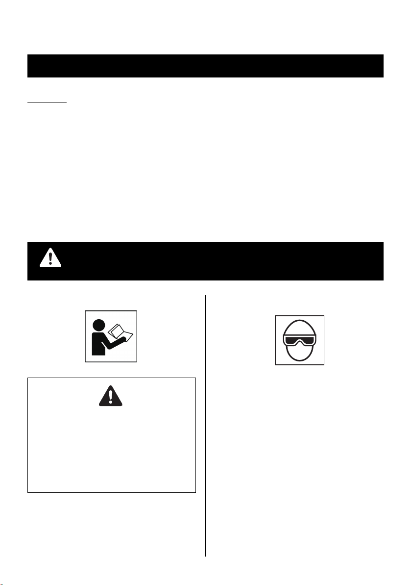
1. WEAR SAFETY GLASSES OR GOGGLES
Danger to the eyes always exists due to the
possibility of dust being blown up by the exhausted air or of a fastener flying up due to
the improper handling of the tool. For these
reasons, safety glasses or goggles shall always be worn when operating the tool.
The employer and/or user must ensure that
proper eye protection is worn. Eye protection
equipment must conform to the requirements of the American National Standards
Institute, ANSI Z87.1 (Council Directive 89/
686/EEC of 21 DEC. 1989) and provide both
frontal and side protection.
The employer is responsible to enforce the
use of eye protection equipment by the tool
operator and all other personnel in the work
area.
3
Page 4
NOTE: Non-side shielded spectacles and
face shields alone do not provide adequate
protection.
2. EAR PROTECTION MAY BE REQUIRED IN SOME ENVIRONMENTS
As the working condition may include exposure to high noise levels which can lead to
hearing damage, the employer and user
should ensure that any necessary hearing
protection is provided and used by the operator and others in the work area.
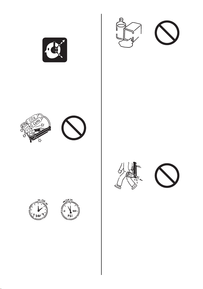
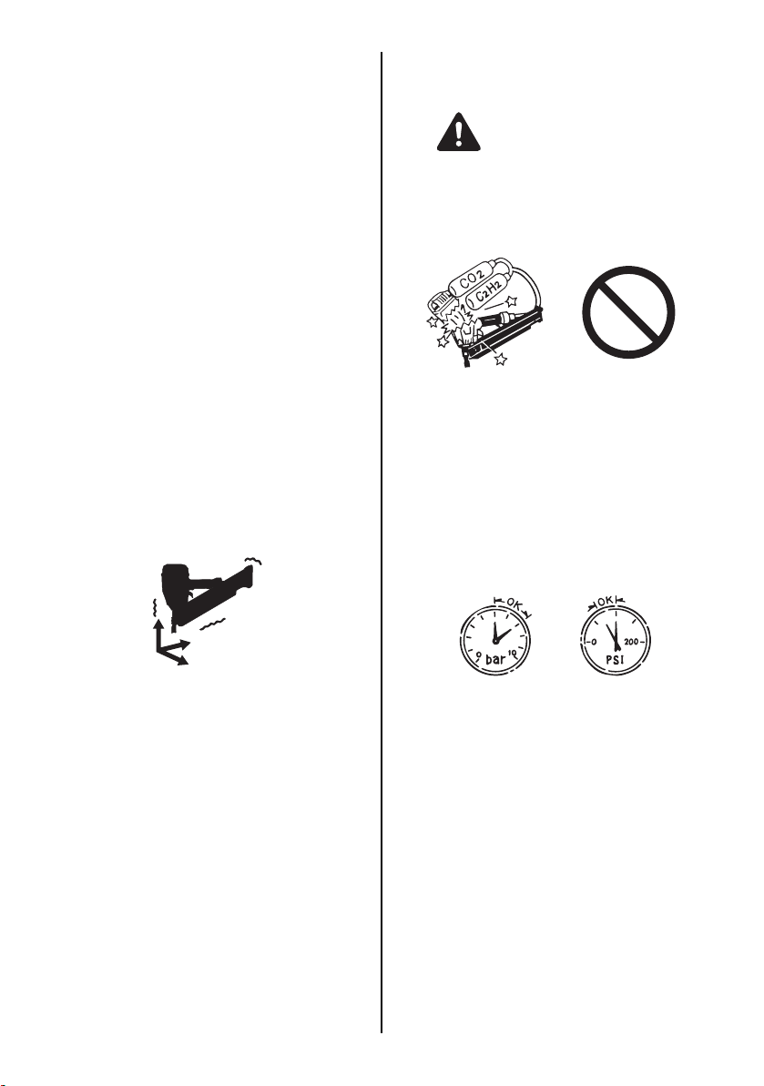
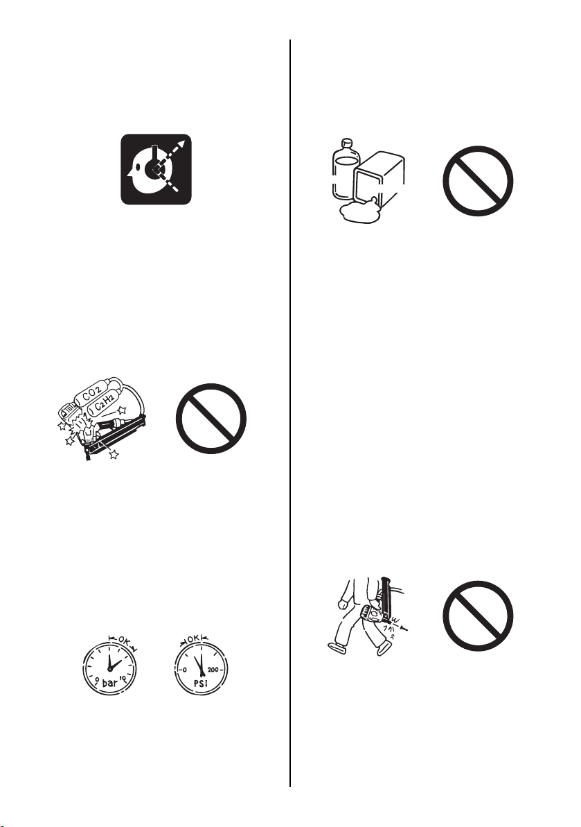
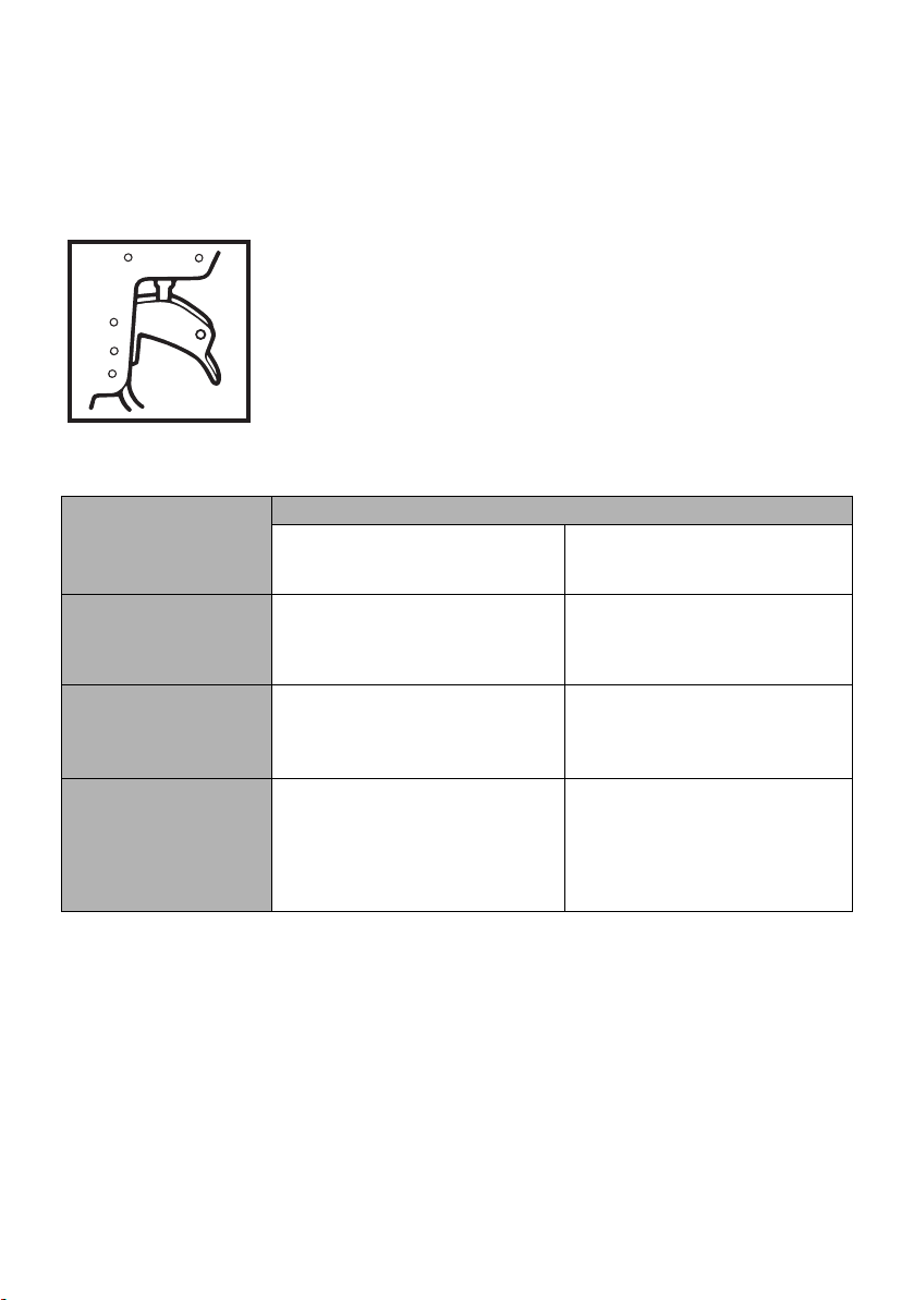
3. DO NOT USE ANY POWER SOURCE EXCEPT AN AIR COMPRESSOR
The tool is designed to operate on compressed air. Do not operate the tool on any
other highpressure gas, combustible gases
(e.g., oxygen, acetylene, etc.) since there is
the danger of an explosion. For this reason,
absolutely do not use anything other than an
air compressor to operate the tool.
Thinner
Gasoline
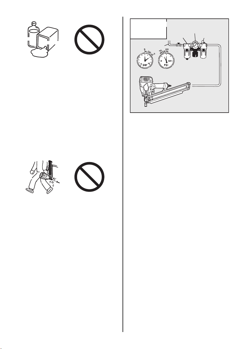
5. DO NOT OPERATE THE TOOL NEAR A FLAMMABLE SUBSTANCE
Never operate the tool near a flammable
substance (e.g., thinner, gasoline, etc.). Volatile fumes from these substances could be
drawn into the compressor and compressed
together with the air and this could result in
an explosion.
6. NEVER USE THE TOOL IN AN EXPLOSIVE ATMOSPHERE
Sparks from the tool may ignite atmospheric
gases, dust or other combustible materials.
7. DO NOT USE A WRONG FITTINGS
The connector on the tool must not hold
pressure when air supply is disconnected. If
a wrong fitting is used, the tool can remain
charged with air after disconnecting and thus
will be able to drive a fastener even after the
air line is disconnected, possibly causing injury.
5
7
100
70
4. OPERATE WITHIN THE PROPER AIR PRESSURE RANGE
The tool is designed to operate within an air
pressure range of 70 to 100 p.s.i. (5 to 7 bar).
The pressure should be adjusted to the type
of the work being fastened. The tool shall
never be operated when the operating pressure exceeds 120 p.s.i. (8 bar).
Never connect the tool to air pressure which
potentially exceeds 200 p.s.i. (14 bar) as the
tool can burst.
8. DISCONNECT THE AIR SUPPLY AND EMPTY THE MAGAZINE WHEN THE TOOL IS NOT IN USE
Always disconnect the air supply from the
tool and empty the magazine when operation
has been completed or suspended, when unattended, moving to a different work area, adjusting, disassembling, or repairing the tool,
and when clearing a jammed fastener.
4
Page 5
9. INSPECT SCREW TIGHTNESS
Loose or improperly installed screws or bolts
cause accidents and tool damage when the
tool is put into operation. Inspect to confirm
that all screws and bolts are tight and properly installed prior to operating the tool.
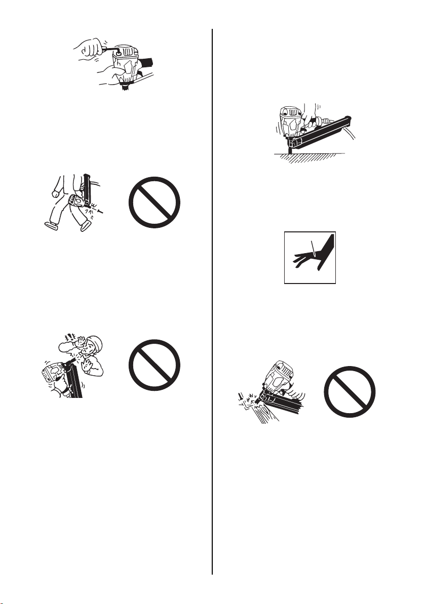
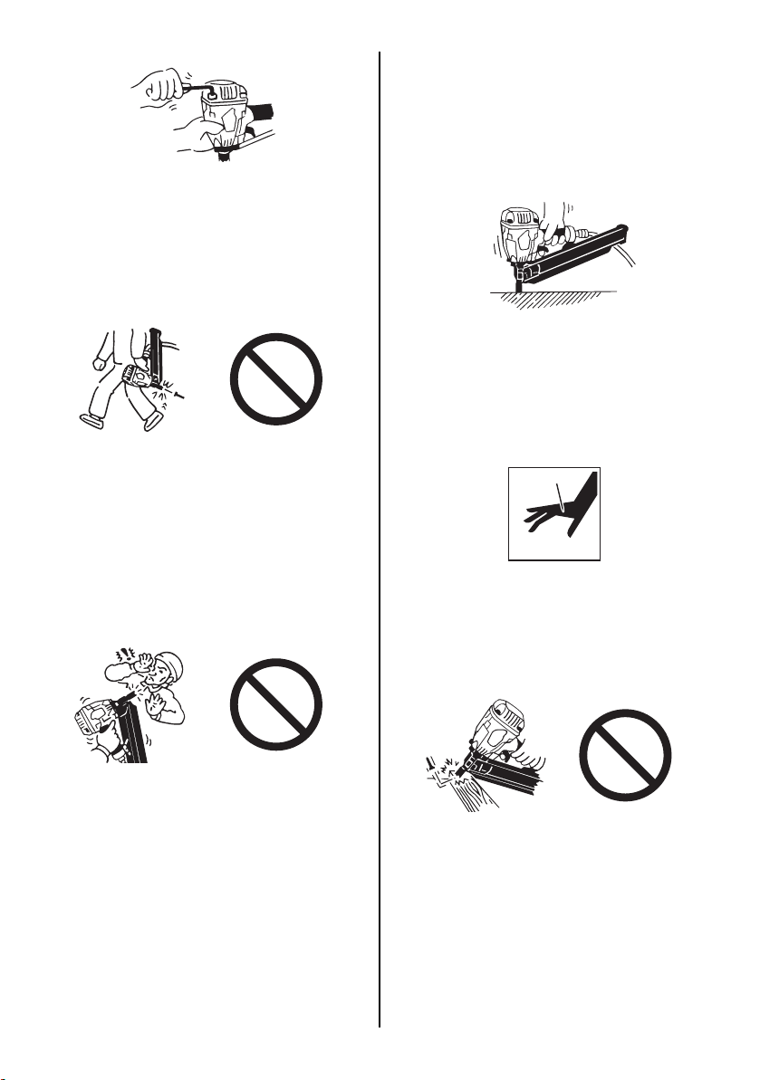
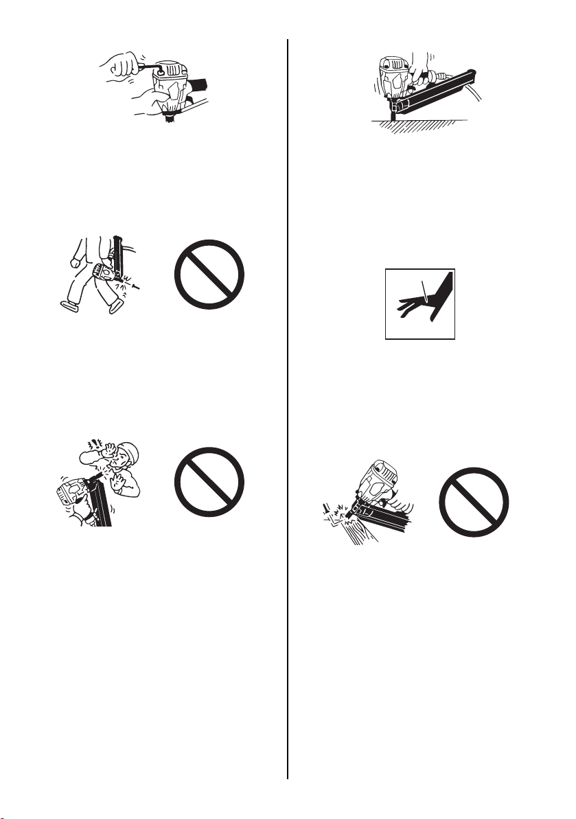
10. DO NOT TOUCH THE TRIGGER UNLESS YOU INTEND TO DRIVE A FASTENER
Whenever the air supply is connected to the
tool, never touch the trigger unless you intend to drive a fastener into the work. It is
dangerous to walk around carrying the tool
with the trigger pulled, and this and similar
actions should be avoided.
12. USE SPECIFIED FASTENERS (SEE PAGE 7)
The use of fasteners other than specified
fasteners will cause the tool malfunction. Be
sure to use only specified fasteners when
operating the tool.
13. PLACE THE DISCHARGE OUTLET ON THE WORK SURFACE PROPERLY
Failure to place the discharge outlet of the
nose in a proper manner can result in a fastener flying up and is extremely dangerous.
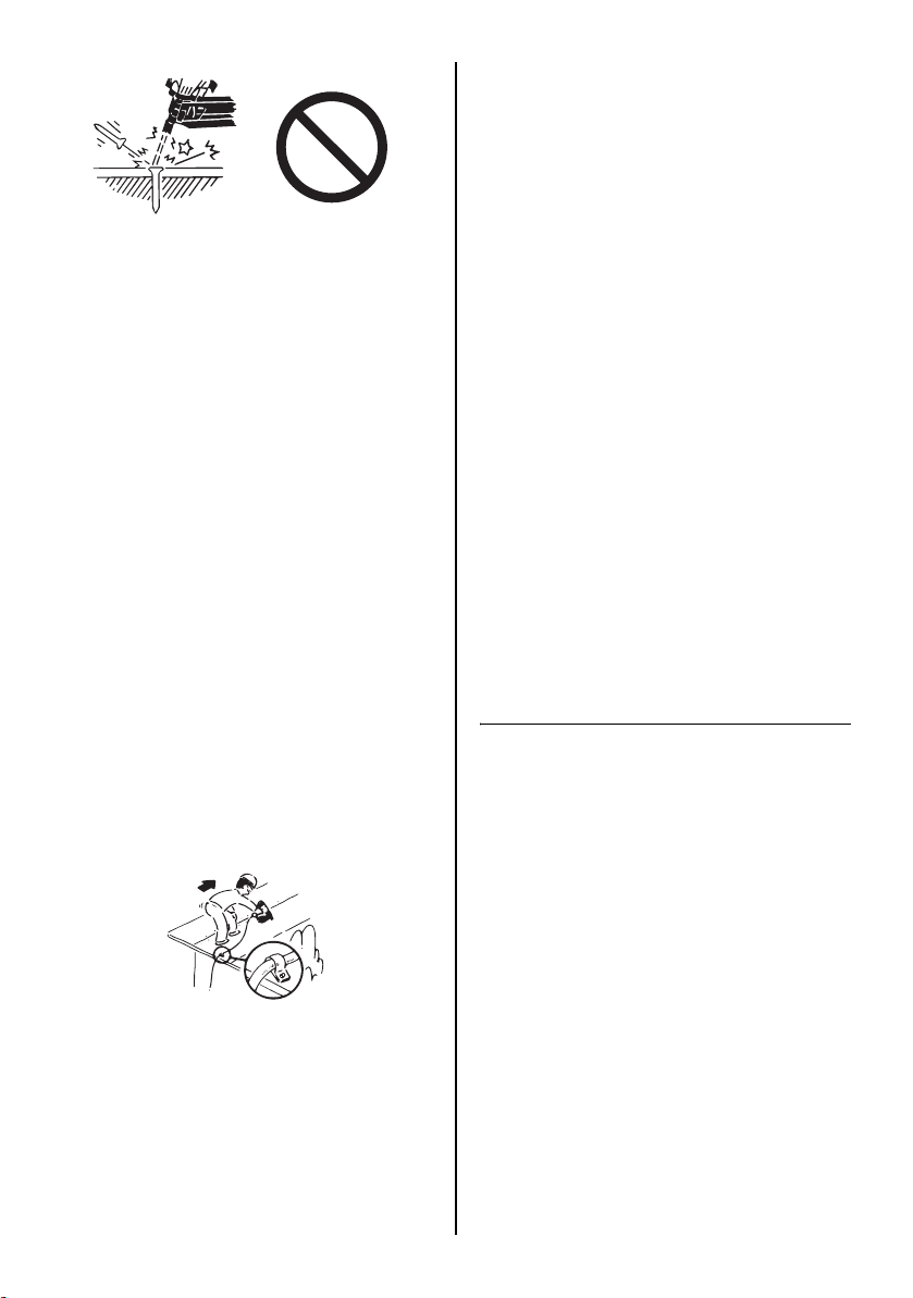
14. KEEP HANDS AND BODY AWAY FROM THE DISCHARGE OUTLET
When loading and using the tool, never
place a hand or any part of body in fastener
discharge area of the tool. It is very dangerous to hit the hands or body by mistake.
11. NEVER POINT THE DISCHARGE OUTLET
TOWARD YOURSELF AND OTHER PERSONNEL
If the discharge outlet is pointed toward people, serious accidents may be caused when
misfiring. Be sure the discharge outlet is not
pointed toward people when connecting and
disconnecting the hose, loading and unloading the fasteners or similar operations.
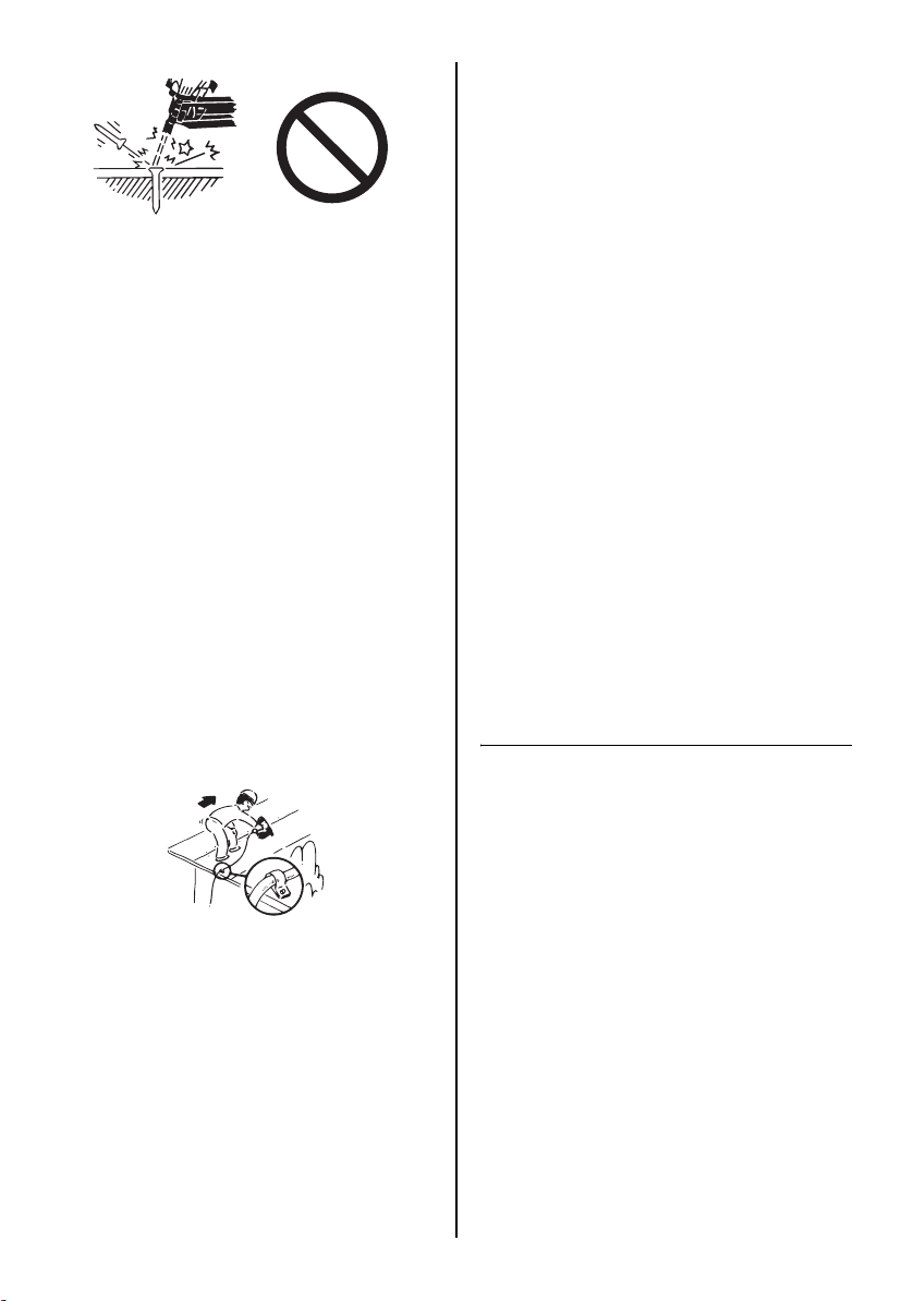
15. DO NOT DRIVE FASTENERS CLOSE TO THE EDGE AND CORNER OF THE WORK AND THIN MATERIAL
The workpiece is likely to split and the fastener could fly free and hit someone.
5
Page 6
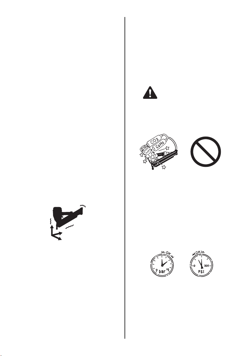
16. DO NOT DRIVE FASTENERS ON TOP OF OTHER FASTENERS
Driving fasteners on the top of other fasteners may cause deflection fasteners which
could cause injury.
17. REMOVING THE FASTENERS AFTER COMPLETING OPERATION
If fasteners are left in the magazine after the
completion of operation, there is the danger
of a serious accident occurring prior to the
resumption of operation, should the tool be
handled carelessly, or when connecting the
air fitting. For this reason, always remove all
fasteners remaining in the magazine after
completion of the operation.
20. NEVER USE THE TOOL IF ANY PORTION
OF THE TOOL CONTROLS (e.g., TRIGGER, CONTACT ARM) IS INOPERABLE,
DISCONNECTED, ALTERED OR NOT
WOKING PROPERLY
21. NEVER ACTUATE THE TOOL INTO FREE SPACE
This will avoid any hazard caused by free flying fasteners and excessive strain of the
tool.
22. ALWAYS ASSUME THAT THE TOOL CONTAINS FASTENERS
23. RESPECT THE TOOL AS A WORKING IMPLEMENT
24. NO HORSEPLAY
25. NEVER LOAD THE TOOL WITH FASTENERS WHEN ANY ONE OF THE OPERATING CONTROLS (e.g., TRIGGER,
CONTACT ARM) IS ACTIVATED
18. CHECK OPERATION OF THE CONTACT TRIP MECHANISM FREQUENTLY IN CASE OF USING A CONTACT TRIP TYPE TOOL
Do not use the tool if the trip is not working
correctly as accidental driving of a fastener
may result. Do not interfere with the proper
operation of the contact trip mechanism.
19. WHEN USING THE TOOL OUTSIDE OR ELEVATED PLACE
When fastening roofs or similar slanted surface, start fastening at the lower part and
gradually work your way up. Fastening backward is dangerous as you may lose your foot
place.
Secure the hose at a point close to the area
you are going to drive fasteners. Accidents
may be caused due to the hose being pulled
inadvertently or getting caught.
26. WEAR THE GLOVES DEPENDING ON THE WORKING CONDITION
27. WHEN DISPOSING THE MACHINE OR ITS
PARTS, FOLLOW THE RELEVANT NATIONAL RULES
OBSERVE THE FOLLOWING GENERAL CAUTION IN ADDITION TO THE
OTHER WARNINGS CONTAINED IN
THIS MANUAL
• Do not use the tool as a hammer.
• Always carry the tool by the grip, never car-
ry the tool by the air hose.
• The tool must be used only for the purpose
it was designed.
• Never remove, tamper with the operating
controls (e.g., TRIGGER, CONTACT ARM)
• Keep the tool in a dry place out of reach of
children when not in use.
• Do not use the tool without Safety Warning
label.
• Do not modify the tool from original design
or function without approval by MAX CO.,
LTD.
6
Page 7
2. SPECIFICATIONS AND TECHNICAL DATA
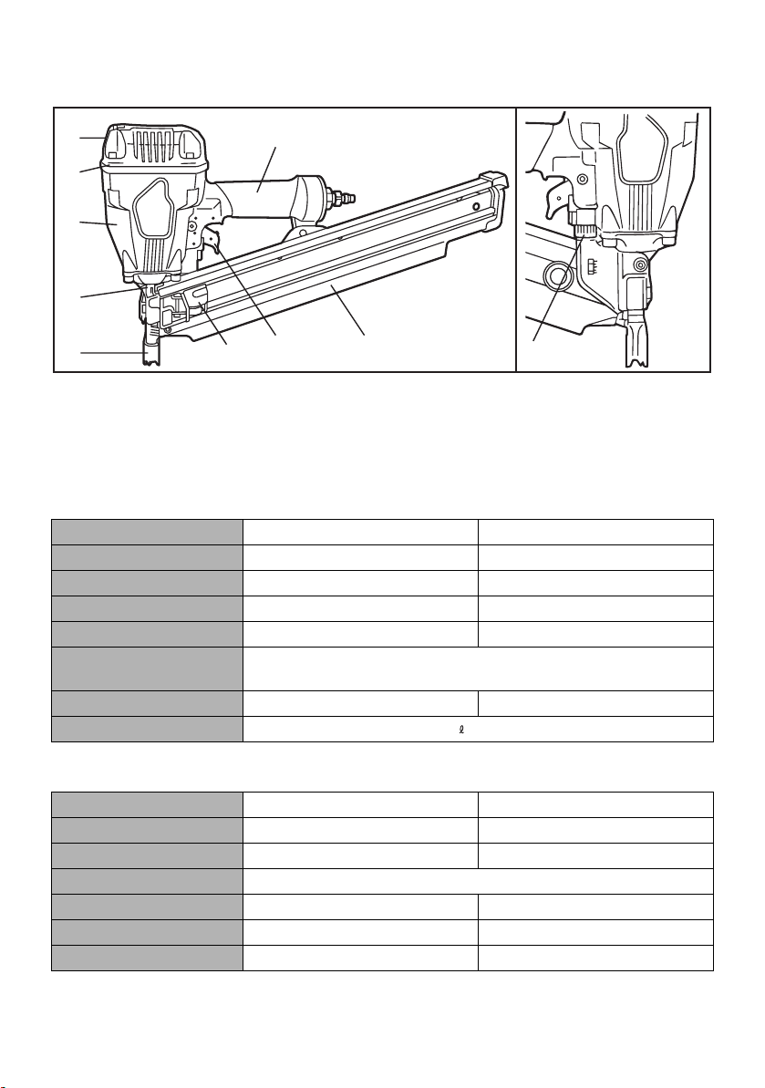
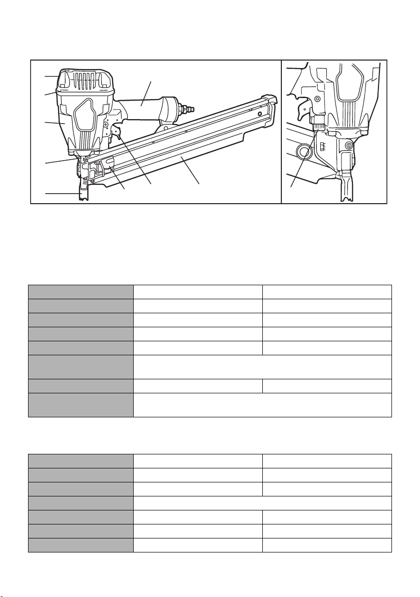
1. NAME OF PARTS
8
7
2
1
4
6
3
1 Frame
2 Cylinder Cap
3 Contact Arm
4 Nose
5 Magazine
2. TOOL SPECIFICATIONS
PRODUCT NO. SN883RH2 SN890CH2<34>
HEIGHT 11-7/8" (300 mm) 12-1/2" (316 mm)
WIDTH 4-3/4" (121 mm) 4-3/4" (121 mm)
LENGTH 20-3/4" (526 mm) 17-1/8" (435 mm)
WEIGHT 7.2 lbs. (3.3 kg) 7.3 lbs. (3.3 kg)
RECOMMENDED
OPERATING PRESSURE
LOADING CAPACITY 64 nails 90 nails
AIR CONSUMPTION 0.077 ft3at 90 p.s.i. (2.1 at 6 bar) operating pressure
9
6 Trigger
7 Grip
8 Exhaust Cover
9 Pusher
0 Adjustment Dial
5
70 to 100 p.s.i. (5 to 7 bar)
0
3. FASTENER SPECIFICATIONS
PRODUCT NO. SN883RH2 SN890CH2<34>
NAIL LENGTH 2" to 3-1/4" (50 to 83 mm) 2" to 3-1/2" (50 to 90 mm)
SHANK DIAMETER .113" to .148" (2.9 to 3.8 mm) .110" to .131" (2.8 to 3.3 mm)
SHANK TYPE Smooth, Ring, Screw
HEAD DIAMETER .267" to .295" (6.8 to 7.5 mm) .256" to .303" (6.5 to 7.7 mm)
COLLATION ANGLE 21 degree 34 degree
HEAD Full round head Clipped head
7
Page 8
TOOL AIR FITTINGS:
This tool uses a 3/8" N.P.T. male plug. The inside diameter should be .39" (9.9mm) or larger.
The fitting must be capable of discharging tool air
pressure when disconnected from the air supply.
RECOMMENDED OPERATING PRESSURE:
70 to 100 p.s.i. (5 to 7 bar). Select the operating
air pressure within this range for best fastener
performance.
DO NOT EXCEED 120 p.s.i. (8 bar).
4. TECHNICAL DATA 1 NOISE
A-weighted single-event sound power level
------ LWA, 1s, d 101.03 dB (SN883RH2)
------ LWA, 1s, d 96.9 dB (SN890CH2<34>)
A-weighted single-event emission sound
pressure level at work station
------ LpA, 1s, d 92.72 dB (SN883RH2)
------ LpA, 1s, d 86.5 dB (SN890CH2<34>)
These values are determined and documented in accordance to EN12549 : 1999.
3. AIR SUPPLY AND CONNECTIONS
WARNING
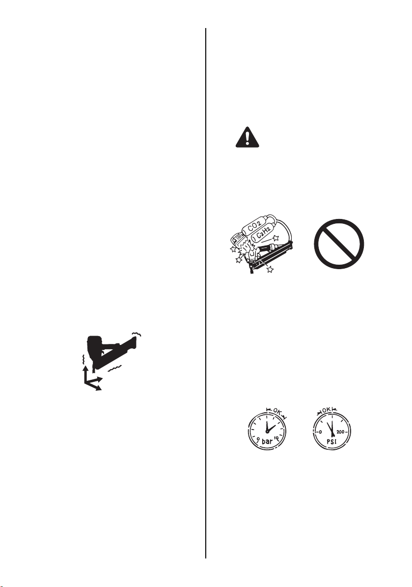
READ SECTION TITLED "SAFETY INSTRUCTIONS"
DO NOT USE ANY POWER SOURCE EXCEPT
AN AIR COMPRESSOR
The tool is designed to operate on compressed
air. Do not operate the tool on any other highpressure gas, combustible gases (e.g., oxygen,
acetylene, etc.) since there is the danger of an
explosion. For this reason, absolutely do not use
anything other than an air compressor to operate
the tool.
2 VIBRATION
Vibration characteristic value
= 4.26 m/s
= 4.5 m/s
These values are determined and documented in accordance to ISO 8662-11.
This value is a tool-related characteristic value and does not represent the influence to the
hand-arm-system when using the tool. An influence to the hand-arm-system when using
the tool will for example depend on the gripping force, the contact pressure force, the
working direction, the adjustment of mains
supply, the workpiece, the workpiece support.
5. APPLICATIONS
∗ Floor and wall framing
∗ Subflooring
∗ Roof and wall sheathing
∗ Fencing
2
(SN883RH2)
2
(SN890CH2<34>)
5
7
OPERATE WITHIN THE PROPER AIR PRESSURE RANGE
The tool designed to operate within an air pressure range of 70 to 100 p.s.i. (5 to 7 bar).
The pressure should be adjusted to the type of
the work being fastened. The tool shall never be
operated when the operating pressure exceeds
120 p.s.i. (8 bar).
8
100
70
Page 9
Thinner
Gasoline
[AIR SUPPLY & CONNECTIONS]
Air compressor
Air hose
Air filter
Regulator
Oiler
DO NOT OPERATE THE TOOL NEAR A FLAMMABLE SUBSTANCE
Never operate the tool near a flammable substance (e.g., thinner, gasoline, etc.). Volatile
fumes from these substances could be drawn
into the compressor and compressed together
with the air and this could result in an explosion.
DO NOT USE A WRONG FITTINGS
The connector on the tool must not hold pressure
when air supply is disconnected. If a wrong fitting
is used, the tool can remain charged with air after
disconnecting and thus will be able to drive a fastener even after the air line is disconnected, possibly causing injury.
DISCONNECT THE AIR SUPPLY AND EMPTY
THE MAGAZINE WHEN THE TOOL IS NOT IN
USE
Always disconnect the air supply from the tool
and empty the magazine when operation has
been completed or suspended, when unattended, moving to a different work area, adjusting,
disassembling, or repairing the tool, and when
clearing a jammed fastener.
3-piece airset
Used at 70 to 100 p.s.i. (5 to 7 bar)
FITTINGS: Install a male plug on the tool which
is free flowing and which will release air pressure
from the tool when disconnected from the supply
source.
HOSES: Hose has a min. ID of 1/4" (6 mm) and
max. length of no more than 17" (5 meters).
The supply hose should contain a fitting that will
provide "quick disconnecting" from the male plug
on the tool.
SUPPLY SOURCE: Use only clean regulated
compressed air as a power source for the tool.
3-PIECE AIRSET (Air filter, Regulator, Oiler):
Refer to TOOL SPECIFICATIONS for setting the
correct operating pressure for the tool.
NOTE:
A filter will help to get the best performance and
minimum wear from the tool because dirt and
water in the air supply are major causes of wear
in the tool.
Frequent, but not excessive, lubrication is required for the best performance. Oil added thru
the air line connection will lubricate the internal
parts.
9
Page 10

4. INSTRUCTIONS FOR OPERATION
READ SECTION TITLED "SAFETY INSTRUCTIONS".
1. BEFORE OPERATION
Check the following prior operation.
1 Wear Safety Glasses or Goggles. 2 Do not connect the air supply. 3 Inspect screw tightness. 4 Check operation of the contact arm & trigger
if moving smoothly.
5 Connect the air supply. 6 Check the air-leakage. (The Tool must not
have the air-leakage.)
7 Hold the Tool with finger-off the trigger, then
push the contact arm against the work-piece.
(The tool must not operate.)
8 Hold the Tool with contact arm free from
work-piece and pull the trigger. (The Tool
must not operate.)
9 Disconnect the air supply.
WARNING
2. OPERATION
Wear safety glasses or goggles danger to the
eyes always exists due to the possibility of dust
being blown up by the exhausted air or of a fastener flying up due to the improper handling of
the tool. For these reasons, safety glasses or
goggles shall always be worn when operating
the tool.
The employer and/or user must ensure that
proper eye protection is worn. Eye protection
equipment must conform to the requirements of
the American National Standards Institute, ANSI
Z87.1 (Council Directive 89/686/EEC of 21 DEC.
1989) and provide both frontal and side protec-
tion.
The employer is responsible to enforce the use
of eye protection equipment by the tool operator
and all other personnel in the work area.
NOTE:
Non-side shielded spectacles and face
shields alone do not provide adequate protection.
WARNING
Keep hands and body away from the discharge
outlet when driving the fasteners because of
dangerous of hitting the hands or body by mistake.
NAIL LOADING
WARNING
•
When loading the nails, be sure to release
the finger from the Trigger.
•
Do not press the Contact Arm against the
object.
Nails
PROCEDURE
1 Load the nails into the slot in the rear of the
Magazine until they go over the Nail Stopper.
Nail Stopper
10
Page 11
Pusher
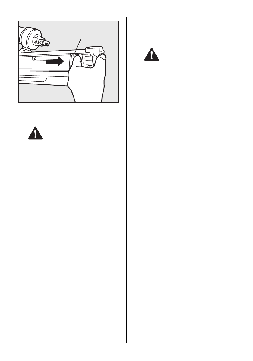
2 Pull the Pusher as far as the rear end of the
magazine and release it gently.
DRIVING FASTENERS
NOTE:
This tool is shipped with SINGLE ACTUATION
selected.
WARNING
•
To avoid double firing or accidental firing,
pull the trigger rapidly and firmly.
•
SINGLE ACTUATION is different from SEQUENTIAL TRIP.
•
The tool with SINGLE ACTUATION drives a
nail each time both when depressing the
Contact Arm while keeping the Trigger
pulled, and when pullimg the Trigger and
keeping it pulled after the Contact Arm depressed.
CAUTION
Abrupt release of the Pusher causes jamming
of nails or dry-firing.
TEST OPERATION
1 Adjust the air pressure at 70 p.s.i. (5 bar) and
connect the air supply.
2 Without touching the trigger, depress the
contact arm against the work-piece.
Pull the trigger. (The tool must fire the fastener.)
3 With the tool off the work-piece, pull the trig-
ger.
Then depress the contact arm against the
work-piece. (The tool must fire the fastener.)
4 Adjust the air pressure as much as the low-
est possible according the length of fastener
and the hardness of work-piece.
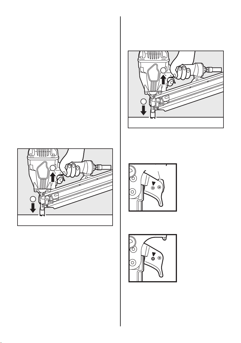
SINGLE ACTUATION OPERATION
For SINGLE ACTUATION operation, keep the
Trigger pulled and depress the Contact Arm
against the work surface, or depress the Contact
Arm against the work surface and pull the Trigger and keep it pulled. Tool cannot fire a second
nail until the Trigger is released and tool can cycle.
11
Page 12
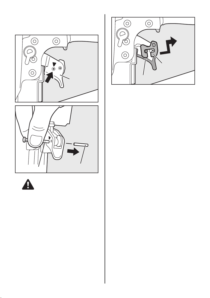
SWITCHING SINGLE ACTUATION TO
CONTACT ACTUATION WITH ANTIDOUBLE FIRE MECHANISM
Spring Pin
Trigger
Punch
WARNING
•
ALWAYS disconnect air supply before
switching the triggering method.
1 Gently push out the Spring Pin which indicat-
ed with " T " mark straight with the punch or
similar tool.
Spring Pin
Switching Lever
2 Remove the Switching Lever to the direction
of the arrow.
NOTE:
When switching back CONTACT ACTUATION
with ANTI-DOUBLE FIRE MECHANISM to SINGLE ACTUATION, equip the Switching Lever
facing "D" mark front with the Spring Pin to the
Trigger by reverse procedure.
12
Page 13

WARNING
•
Use sintering steel grey metallic color Switching Lever
Confirm and use the designated original Switching Lever when carrying out the switching back
procedure.
The use of Switching Lever other than the designated original one will cause serious accidents.
(e.g., firing fasteners just pulling trigger, etc.)
Color Shape (1/1 scale) Tool
SINTERING STEEL
GREY METALLIC
STAINLESS SILVER
STEEL BLACKENING HS90A
•
Never install the Switching Lever to the Previous model
NF550, SN883, and
SN883 with thin trigger
SN883 and SN890 with
thick trigger
It will cause serious accidents. (e.g., firing fasteners just pulling trigger, etc)
Projection Shape
Flat Shape
This model Another model
13
Page 14
CONTACT TRIP MODEL with ANTI-DOUBLE
FIRE MECHANISM
The anti-double fire mechanism (US patent
5597106, UK patent 2286790) is installed on this
tool.
The common operating procedure on "Contact
Trip" tools is for the operator to contact the work
to actuate the trip mechanism while keeping the
trigger pulled, thus driving a fastener each time
the work is contacted. This will allow rapid fastener placement on many jobs, such as sheathing, decking and pallet assembly. All pneumatic
tools are subject to recoil when driving fasteners.
The tool may bounce, releasing the trip, and if
unintentionally allowed to re-contact the work
surface with the trigger still actuated (finger still
holding trigger pulled) an unwanted second fastener will be driven.
SINGLE FIRE OPERATION (ANTI-DOUBLE
FIRE MECHANISM)
For single fire operation, depress the Contact
Arm against the work surface and pull the Trigger. Tool cannot fire a second nail until the Trigger is released and tool can cycle.
2
1
CONTACT FIRE OPERATION
For contact fire operation, hold the Trigger and
depress the Contact Arm against the work surface.
1
2
PROCEDURE
1 Hold the Trigger. 2 Depress the Contact Arm.
PROCEDURE
1 Depress the Contact Arm. 2 Pull the Trigger.
MODEL IDENTIFICATION
Switching Lever
SINGLE ACTUATION
Identified by SWITCHING LEVER.
CONTACT TRIP WITH ANTI-DOUBLE FIRE
MECHANISM
(US patent 5597106, UK patent 2286790)
Identified by RED TRIGGER.
The Switching Lever is removed.
14
Page 15
SEQUENTIAL TRIP
The Sequential Trip requires the operator to hold the tool against the work before pulling the trigger. This
makes accurate fastener placement easier, for instance on framing, toe nailing and crating applications.
The Sequential Trip allows exact fastener location without the possibility of driving a second fastener on
recoil, as described under "Contact Trip".
The Sequential Trip Tool has a positive safety advantage because it will not accidentally drive a fastener
if the tool is contacted against the work-or anything else-while the operator is holding the trigger pulled.
SEQUENTIAL TRIP
Identified by ORANGE TRIGGER.
PROCEDURE
1 Pulling the Trigger and keeping it
pulled.
2 Depressing the Contact Arm.
SINGLE ACTUATION • The tool fires a nail.
• The tool cannot fire a second nail
until the Trigger is released.
CONTACT ACTUATION
WITH ANTI-DOUBLE
The tool fires a nail each time when
the Contact Arm is depressed.
FIRE MECHANISM
1 Depressing the Contact Arm. 2 Pulling the Trigger and keeping
it pulled.
• The tool fires a nail.
• The tool cannot fire a second nail
until the Trigger is released.
• The tool fires a nail.
• The tool cannot fire a second nail
until the Trigger is released.
SEQUENTIAL TRIP The tool cannot fire a nail. • The tool fires a nail.
• The tool cannot fire a second nail
until the Trigger is released and
the Contact Arm is left work surface.
15
Page 16
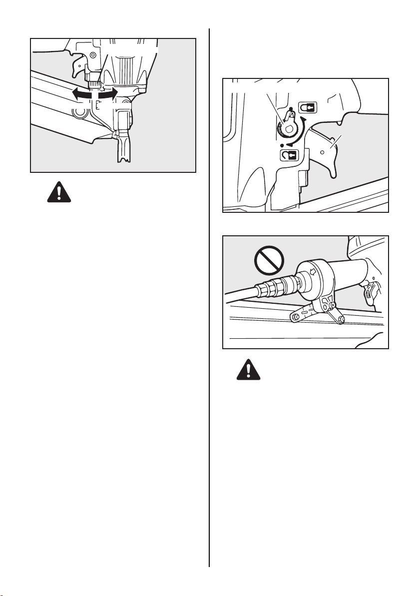
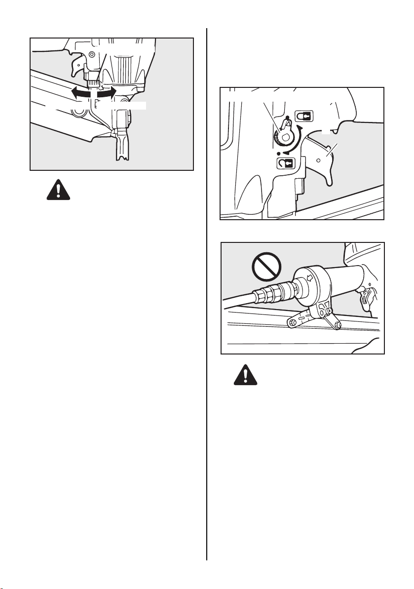
DRIVING DEPTH ADJUSTMENT
Adjustment Dial
TRIGGER LOCK MECHANISM
The tool is equipped with a Trigger Lock Mechanism. Push and rotate the Trigger from LOCK to
the Trigger UNLOCK position before driving
nails.
Trigger Lock Dial
Deeper Shallower
WARNING
ALWAYS disconnect air supply before making
adjustment.
The driving depth adjustment is made by adjusting the Adjustment Dial.
1 With air pressure set, drive a few nails into a
representative material sample to determine
if adjustment is necessary.
2 If adjustment is required, disconnect air sup-
ply.
3 Refer to the mark on the Contact Arm area
for direction to turn the Adjustment Dial.
4 Re-connect air supply.
LOCK
Trigger
UNLOCK
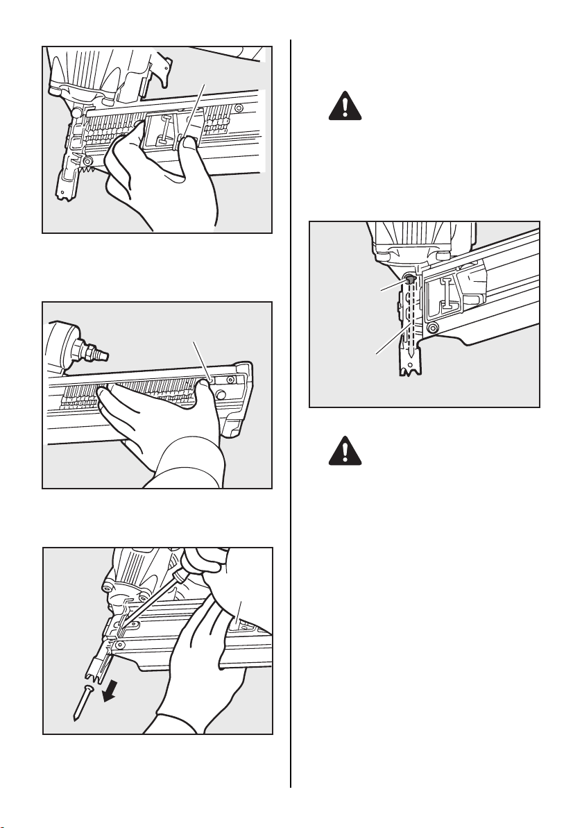
REMOVING JAMMED NAILS
WARNING
ALWAYS disconnect air supply before removing jammed nails.
16
Page 17
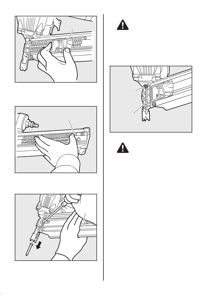
Pusher Lever
WARNING
When removing the jammed nail, wear the
gloves.
Do not remove the jammed nail with your bare
hands.
PROCEDURE
1 Push down the Pusher Lever and release
the strip nails from the Pusher.
Nail Stopper
2 Push the Nail Stopper, and remove the strip
nails from inside of the Magazine.
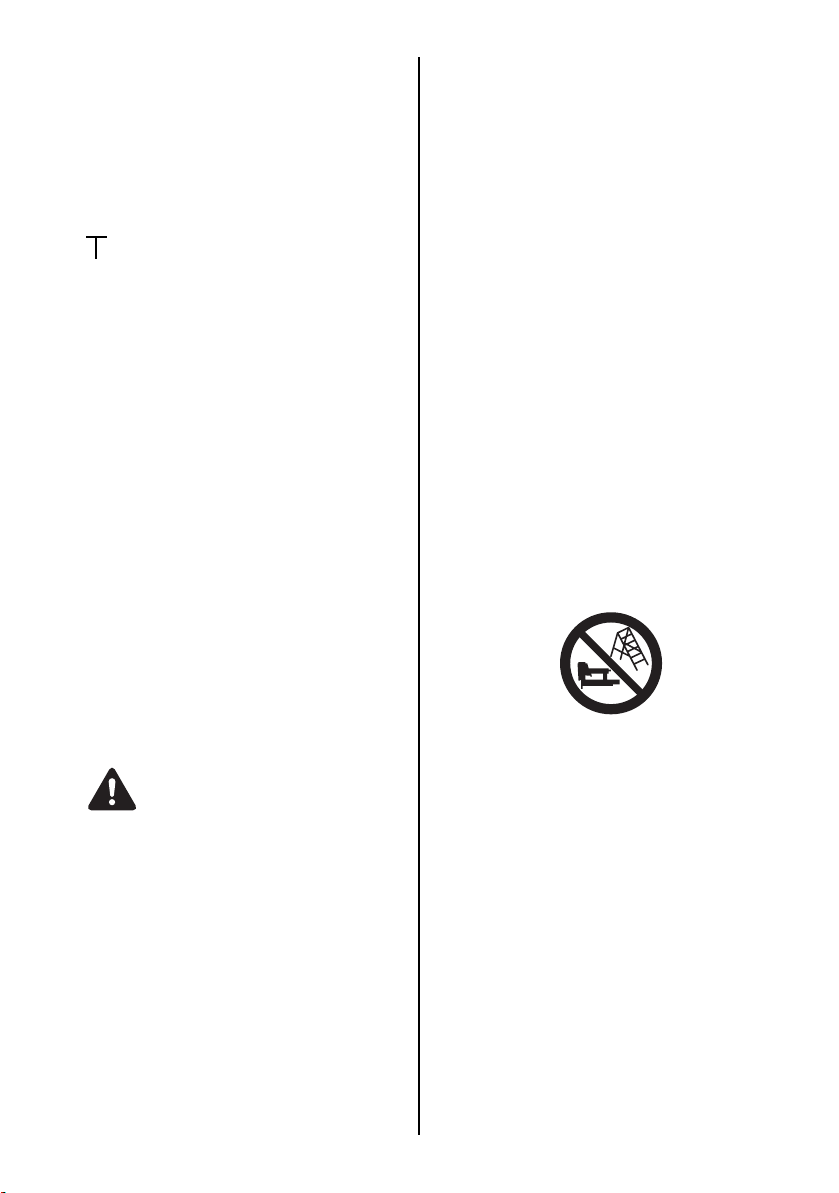
Pusher
Magnet
Remaining nail
(SN883RH2 only)
WARNING
Nails are held in the Nose of the tool by magnet. (SN883RH2 only)
This tool equips a magnet in the Nose to drive
out all nails loaded in the Magazine. Therefore,
in the case the collation strip is broken, there are
nails remaining in the Nose even if you think that
you removed whole nails. In this case, there is
possibility of serious accident if you think that
there are no nails and activate the tool. For that
reason, when you remove the nails from the
Magazine, confirm that there are no nails in the
Nose besides disconnect air supply.
3 Pull and stayed the Pusher with hand. 4 Remove the jammed nail from the Nose us-
ing a punch or a slotted screw driver.
17
Page 18
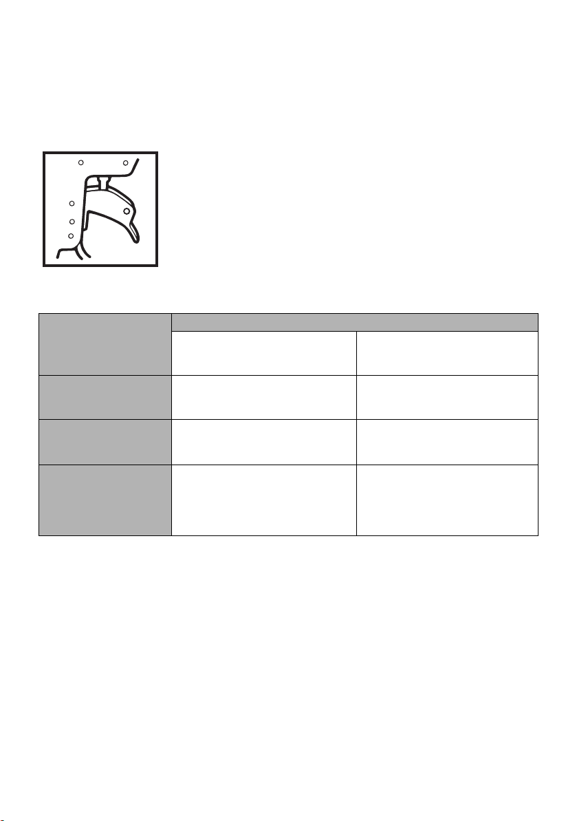
5. MAINTENANCE FOR PERFORMANCE
1 ABOUT PRODUCTION YEAR
This product bears production number at the
lower part of the grip of the main body. The
two digits of the number from left indicates
the production year.
(Example)
0 8 8 2 6 0 3 5 D
Year 2008
2 DO NOT FIRE THE NAILER WHEN IT IS
EMPTY
3 USE A 3-PIECE AIRSET
Failure to use a 3-piece airset allows the
moisture and dirt inside compressor to pass
into the tool directly. This causes rust and
wear, and results in a poor operating performance. The hose length between airset
and tool should be no longer than 5 m since
a longer length results in a reduction in air
pressure.
4 USE RECOMMENDED OIL
The velocite or turbine oil should be used to
lubricate the tool. Upon completion of operations, place 2 or 3 drops of oil into the air plug
inlet with the jet oiler. (Recommended Oil :
ISO VG32)
5 INSPECT AND MAINTAIN DAILY OR BE-
FORE OPERATION
WARNING
Disconnect air supply and empty the magazine when inspecting or maintaining the tool.
(1) Drain air line filter and compressor
(2) Keep lubricator filled in air 3-pieces set
(3) Clean filter element of air 3-pieces set
(4) Tighten all screws
(5) Keep contact arm moving smoothly
6. STORAGE
1 When not in use for an extended period, ap-
ply a thin coat of the lubricant to the steel
parts to avoid rust.
2 Do not store the tool in a cold weather envi-
ronment. Keep the tool in a warm area.
3 When not in use, the tool should be stored in
a warm and dry place. Keep out of reach of
children.
4 All quality tools will eventually require servic-
ing or replacement of parts because of wear
from the normal use.
7. TROUBLE SHOOTING/REPAIRS
The troubleshooting and/or repairs shall be carried out only by the MAX CO., LTD. authorised
distributors or by other specialists.
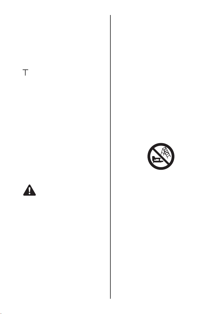
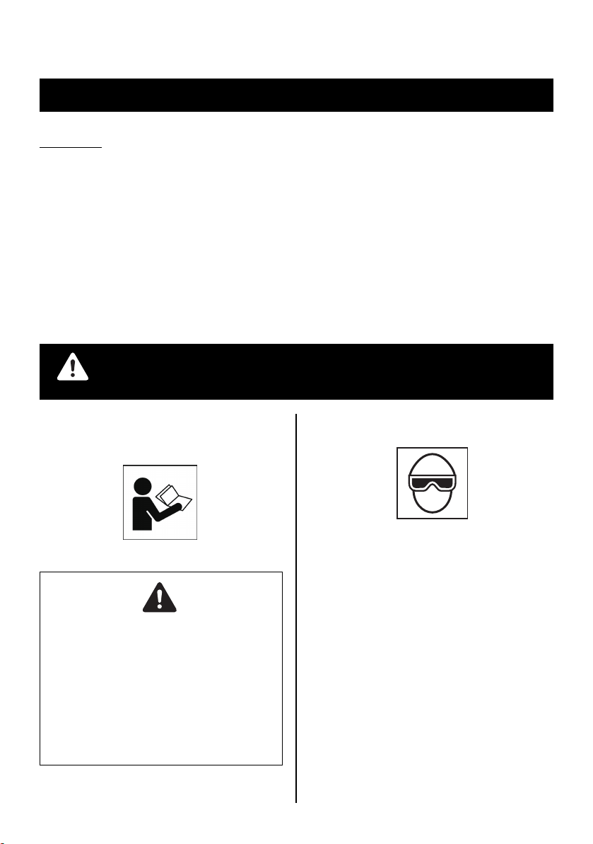
Supplement to the operating instruction
According to the European Norm EN 792-13 the
regulation is valid from 01.01.2001 that all fastener driving tools with contact actuation must be
marked with the symbol "Do not use on scaffoldings, ladders" and they shall not be used for specific application for example:
∗ when changing one driving location to another
involves the use of scaffoldings, stairs, ladders
or ladder alike constructions e.g. roof laths,
∗ closing boxes or crates,
∗ fitting transportation safety systems e.g. on ve-
hicles and wagons.
18
Page 19

FRANÇAIS
MANUEL D’UTILISATION ET D’ENTRETIEN
INDEX
1. CONSIGNES DE SECURITE ...........................................19
2. CARACTERISTIQUES TECHNIQUES ET ACCESSOIRES... 23
3. ALIMENTATION EN AIR COMPRIME ET CONNEXIONS .....24
4. INSTRUCTIONS D’EMPLOI.............................................26
5. ENTRETIEN...................................................................... 34
6. EMMAGASINAGE ............................................................34
7. REPARATION ..................................................................34
AVANT D’UTILISER CET OUTIL, LIRE CE MANUEL ET LES CONSIGNES DE SECURITE AFIN DE
GARANTIR UN FONCTIONNEMENT SUR.
AVERTISSEMENT
CONSERVER CE MANUEL EN LIEU SUR AVEC L’OUTIL AFIN DE POUVOIR LE CONSULTER
ULTERIEUREMENT.
1. CONSIGNES DE SECURITE
AVERTISSEMENT
AFIN D’EVITER DES DOMMAGES
CORPORELS OU MATERIELS
AVANT D’UTILISER L’OUTIL, LIRE
ATTENTIVEMENT CE MANUEL ET
PRENDRE CONNAISSANCE DES
“CONSIGNES DE SECURITE” SUIVANTES.
LE MANQUEMENT AUX CONSIGNES DE
MISE EN GARDE PEUT ENTRAÏNER LA
MORT OU DES BLESSURES GRAVES.
PRECAUTIONS D’EMPLOI DE L’OUTIL
1. PORTEZ DES LUNETTES
PROTECTRICES OU DE SÉCURITÉ
Il existe toujours un risque de danger pour les
yeux provoqué par les poussières soufflées par
l’air échappé ou par la projection en l’air de
l’élément de fixation due à une manipulation
inadéquate de l’outil. Pour cette raison, des
verres de sécurité ou des lunettes de protection
doivent toujours être portées pendant
l’utilisation de l’outil. L’employeur et/ou
l’utilisateur doit s’assurer qu’un équipement de
protection des yeux approprié est porté.
L’équipement de protection des yeux doit
assurer la protection frontale et latérale à la fois.
L’employeur se doit d’obliger l’opérateur d’outil
et l’ensemble du personnel présent sur le lieu de
travail à porter des lunettes de protection des
yeux.
19
Page 20
REMARQUE: Des lunettes sans blindage
latéral et des équipements de protection de
la face seuls n’assurent pasune protection
appropriée. Directive européenne 89/686/
CEE du 21 décembre 1989.
utilisé lorsque la pression de fonctionnement
dépasse 120 p.s.i. (8 bar).
Ne jamais brancher d’outil sur l’alimentation
en air comprimé dont la pression peut
éventuellement dépasser 200 p.s.i. (14
bars), l’outil risquant d’exploser.
2. DANS CERTAINS ENVIRONNEMENTS UNE PROTECTION AUDITIVE PEUT ETRE EXIGEE
Etant donné que les conditions de travail
peuvent entraîner une exposition à des
niveaux de bruit élevés qui peuvent provoquer
des dommages d’audition, l’employeur et
l’utilisateur doivent s’assurer qu’un équipement
de protection auditive est mis àdisposition et
utilisé par l’opérateur et les autres personnes
se trouvant sur le lieu de travail.
3. NE PAS UTILISER D’AUTRE SOURCE D’ALIMENTATION QU’UN COMPRESSEUR D’AIR
L’outil est concu pour fonctionner avec de l’air
comprimé. Ne pas utiliser l’outil avec d’autres
gaz sous haute pression, des gaz
combustibles (ex. l’oxygène, l’acétylène, etc.),
car il y a risque d’explosion. Par conséquent,
ne rien utiliser d’autre que le compresseur d’air
pour faire fonctionner cet outil.
Diluant
Essence
5. NE PAS UTILISER L’OUTIL PRES D’UNE SUBSTANCE INFLAMMABLE
Ne jamais utiliser l’outil près d’une substance
inflammable (ex. diluant, de l’essence, etc.).
Les fumées volatiles de ces substances
peuvent être attirées dans le compresseur,
comprimées en même temps avec l’air, cela
risquant de produire une explosion.
6. N’UTILISEZ JAMAIS L’OUTIL DANS UNE AMBIANCE EXPLOSIVE
Les étincelles de l’outil peuvent mettre à feu
les gaz atmosphériques, la poussière ou
d’autres matériaux combustibles.
7. NE PAS UTILISER DES ELEMENTS DE FIXATION INADEQUATS
Le connecteur sur l’outil ne doit pas retenir la
pression lorsque l’admission d’air est
débranchée. Si une fixation non appropriée
est utilisée, l’outil peut rester chargé d’air
après le débranchement et sera ainsi capable
d’enfoncer un élément de fixation même
après le débranchement de l’arrivée d’air,
provoquant ainsi des dommages éventuels.
5
7
100
70
4. RESPECTER LA PLAGE DE PRESSION D’AIR APPROPRIEE POUR L’UTILISATION
L’outil est concu pour fonctionner dans une
plage de pression de 70 à 100 p.s.i. (5 à 7 bar).
La pression doit être ajustée au type de
pièce à clouer. L’outil ne doit jamais être
8. COUPER L’ALIMENTATION EN AIR COMPRIME ET VIDER LE MAGASIN LORSQUE L’OUTIL N’EST PAS UTILISE
Veillez à toujours débrancher l’arrivée d’air de
l’outil et à vider le magasin en fin de travail ou
lorsque le travail est suspendu, lorsque l’outil
est laissé sans surveillance, est déplacé vers un
autre lieu de travail, réglé, démonté ou réparé,
ou encore lorsque vous dégagez un fermoir.
20
Page 21
9. CONTROLER LE SERRAGE DES VIS
Des vis ou des boulons desserrés ou
incorrectement installés peuvent provoquer
des accidents et endommager l’outil lorsqu’il
est mis en service. Contrôler et vérifier que
tous les vis et boulons sont bien serrés et
correctement installés avant d’utiliser l’outil.
10. NE PAS TOUCHER LE DECLENCHEUR SAUF POUR ENFONCER UN ELEMENT DE FIXATION
Chaque fois que l’arrivée d’air est connectée
à l’outil, ne jamais toucher le déclencheur
sauf si on a l’intention d’enfoncer des
éléments de fixation dans la pièce. ll est
dangereux de porter l’outil tout en marchant
avec le déclencheur enclenché. Ceci, ainsi
que des actions similaires doivent être évités.
12. UTILISER LES ELEMENTS DE FIXATION APPROPRIÉS
L’utilisation d’éléments de fixation autres
que ceux spécifiés provoque le mauvais
fonctionnement de l’outil. Sassurer d’utiliser
uniquement les éléments de fixation
appropriés avec l’outil.
13. PLACER CORRECTEMENT LA SORTIE DE DÉCHARGE SUR LA SURFACE DE TRAVAIL
Si l’on oublie de placer la sortie de décharge
du nez de façon appropriée, on risque
d’avoir comme conséquence un
détachement violent de l’attache vers le haut
et ceci est extrêmement dangereux.
14. ELOIGNER VOTRE CORPS ET VOS MAINS DU NEZ DE L’APPAREIL
Lors du chargement et de l’utilisation de l’outil,
ne jamais placer votre main ou une partie de
votre corps dans la zone de décharge de
l’élément de fixation de l’outil.
11. NE JAMAIS DIRIGER L’ORIFICE DE REFOULEMENT VERS VOUS OU VERS UNE AUTRE PERSONNE
En cas de râté, les personnes qui se
trouveraient dans la trajectoire de l’orifice de
refoulement risquent d’être grièvement
blessées. Lorsque vous branchez ou
débranchez le tuyau, montez ou démontez
les fermoirs ou effectuez une intervention
quelconque, vérifiez toujours que l’orifice de
refoulement n’est orienté vers personne.
15. NE PAS APPLIQUER LES ELEMENTS DE FIXATION PRES DU BORD DE LA PIECE ET SUR UN MATERIAU MINCE
La pièce a tendance à éclater et l’élément de
fixation risque de sauter et de heurter
quelqu’un. Faire attention lors de la fixation
d’un matériau mince ou près des bords et
des coins de la pièce.
21
Page 22
16. NE PAS ENFONCER DES POINTES OU AGRAFES SUR D’AUTRES ELEMENTS DE FIXATION
Le fait d’enfoncer des éléments de fixation par
dessus d’autres éléments de fixation risque de
provoquer un éclatement de ces élément qui
pourrait provoquer des blessures.
17. RETRAIT DES PROJECTILES APRES LA FIN DE L’OPERATION
Si les projectiles sont laissés dans le magasin
après la fin de l’opération, il y a danger
d’accident grave qui risque de se produire avant
la reprise de l’opération, au cas où l’outil est
manipulé négligemment ou lors du branchement
de la fixation d’air. Par conséquent, toujours
enlever tous les projectiles restant dans le
changeur après la fin de l’opération.
18. VERIFIER FREQUEMMENT LE FONCTIONNEMENT DU MECANISME DE DECLENCHEMENT AU COUP À COUP EN CAS D’UTILISATION D’UN OUTIL DE TYPE A DECLENCHEMENT AU COUP À COUP
Ne pas utiliser l’outil si le déclencheur ne
fonctionne pas correctement, car un
enfoncement accidentel d’un projectile de
fixation risque de se produire. Ne pas gêner
le fonctionnement correct du mécanisme de
déclenchement au coup à coup.
19. UTILISATION DE L’OUTIL A L’EXTERIEUR OU SUR UN ENDROIT SURELEVE
Pour fixer un toit, ou une surface similaire
inclinée, commencer la fixation sur la partie
inférieure et exécuter le travail en montant
progressivement. ll est dangereux de faire
des fixations en reculant, car on risque de
perdre pied en glissant.
Fixer le tuyau à un point près de la zone où les
éléments de fixation doivent être enfoncés. Des
accidents risquent de se produire à cause d’un
tuyau coincé ou tiré par inadvertance.
20. NE JAMAIS UTILISER L’OUTIL SI N’IMPORTE QUELLE PARTIE DES COMMANDES D’OUTIL (PAR EXEMPLE, DÉCLENCHEUR, BRAS DE CONTACT) EST INOPÉRABLE, DÉBRANCHÉE, CHANGÉE OU NE FONCTIONNANT PAS CORRECTEMENT
21. NE JAMAIS LANCER LES POINTES DANS UN ESPACE LIBRE
Les pointes voltigeant dans l’air présentent
un certain danger;
22. TOUJOURS PRÉSUMER QUE L’OUTIL EST MUNIS DE FERMOIRS
23. CONSIDEREZ L’OUTIL COMME UN INSTRUMENT DE TRAVAIL
24. NE FAITES PAS DE GESTES BRUSQUES
25. NE JAMAIS MONTER LES FERMOIRS SUR L’OUTIL LORSQU’UNE COMMANDE (DÉTENTE OU BRAS DE CONTACT par exemple) EST ACTIVÉE
26. PORTEZ DES GANTS SELON LES CONDITIONS DE TRAVAIL
27. LORSQUE LA MACHINE OU SES PIECES SONT MISES AU REBUT, SUIVEZ LES REGLEMENTS NATIONAUX RELATIFS
RESPECTER LES PRECAUTIONS
GENERALES SUIVANTES EN PLUS
DES AUTRES AVERTISSEMENTS
DECRITS DANS CE MANUEL
• Ne pas utiliser l’outil comme un marteau.
• Toujours porter l’outil par la poignée, ne
jamais porter l’outil par tuyau d’air.
• L’outil doit être utilisé uniquement pour
l’usage préconisé.
• Ne jamais retirer ou altérer les commandes
(DÉTENTE OU BRAS DE CONTACT par
exemple).
• Conserver l’outil dans un endroit sec, hors
de portée des enfants, lorsqu’il n’est pas
utilisé.
• Ne pas utiliser l’outil sans l’étiquette de
sécurité.
• Ne pas modifier la conception originale ou
les caractéristiques de l’outil sans le
consentement de MAX CO. LTD.
22
Page 23

2. CARACTERISTIQUES TECHNIQUES ET ACCESSOIRES
1. NOM DES PIÈCES
8
7
2
1
4
6
3
1 Boîtier
2 Couvercle de cylindre
3 Barre de contact
4 Nez
5 Magasin
2. SPÉCIFICATIONS DE L’OUTIL
Produit No. SN883RH2 SN890CH2<34>
Hauteur 11-7/8" (300 mm) 12-1/2" (316 mm)
Largeur 4-3/4" (121 mm) 4-3/4" (121 mm)
Longeur 20-3/4" (526 mm) 17-1/8" (435 mm)
Poids 7.2 lbs. (3.3 kg) 7.3 lbs. (3.3 kg)
Pression de service
recommandée
Capacite de charge 64 pointes 90 pointes
Consommation en air
comprimé
∗ De conception compacte, cet outil peut être utilisé dans un espace réduit.
9
6 Levier de commande
7 Poignée
8 Capot d’aspiration
9 Poussoir
0 Disque de réglage
Pression de fonctionnement 2,1l à 6 barres (0,007 pieds 3 à 90 p.s.i.)
5
70 à 100 p.s.i. (5 à 7 bar)
0
3. SPÉCIFICATS DU MATÉRIEL DE FIXATION
Produit No. SN883RH2 SN890CH2<34>
Longueur de pointe 2" à 3-1/4" (50 à 83 mm) 2" à 3-1/2" (50 à 90 mm)
Diamètre de tige .113" à .148" (2.9 à 3.8 mm) .110" à .131" (2.8 à 3.3 mm)
Type de queue Tige droite, annulaire, filetée Tige droite, annulaire, filetée
Diamètre de tête .267" à .295" (6.8 à 7.5 mm) .256" à .303" (6.5 à 7.7 mm)
Angle de fixation 21 degrés 34 degrés
Tête Tête complètement ronde Tête taillée
23
Page 24
PIECES DE RACCORDEMENT D’AIR
COMPRIME
Cet appareil est équipé d’une prise mâle avec
filet extérieur de 9.5 mm pouce. Le diamètre
intérieur devrait être de 9.9 mm au moins. Le
raccord doit permettre de décharger l’air
comprimé de l’appareil lorsque l’alimentation en
air comprimé est interrompue.
PRESSION DE SERVICE RECOMMANDEE:
De 70 à 100 p.s.i. (5 à 7 bars). Régler l’air
comprimé à l’intérieur de cette plage pour garantir
la meilleure performance possible de fixation.
LA PRESSION DE SERVICE NE DOIT PAS
DEPASSER 120 p.s.i. (8 BARS)
4. CARACTÉRISTIQUES TECHNIQUES
1 BRUIT
Niveau de puissance sonore pulsée par
rapport à la courbe A
------ LWA, 1s, d 101.03 dB (SN883RH2)
------ LWA, 1s, d 96.9 dB (SN890CH2<34>)
Niveau de pression acoustique pulsée par
rapport à la courbe A
------ LpA, 1s, d 92.72 dB (SN883RH2)
------ LpA, 1s, d 86.5 dB (SN890CH2<34>)
au poste de travail
Ces valeurs out été calculées et documentées,
en conformité avec EN12549: 1999.
5. APPLICATIONS
∗ Pose de plinthes au sol et mur
∗ Pose de faux-fonds
∗ Revêtement de doit et mur
∗ Cloisonnage
3. ALIMENTATION EN AIR COMPRIME ET CONNEXIONS
AVERTISSEMENT
LIRE LE PARAGRAPHE INTITULÉ
“CONSIGNES DE SECURITE”.
NE PAS UTILISER UNE AUTRE SOURCE
D'ALIMENTATION EXCEPTE UN
COMPRESSEUR D'AIR
L’outil est conçu pour fonctionner avec de l’air
comprimé Ne pas utiliser l’outil avec d’autres gaz
sous haute pression, des gaz combustibles(ex.
l’oxygène, l’acétylène, etc.), car il y a risque
d’explosion. Par conséquent, ne rien utiliser
d’autre que le compresseur d’air pour faire
fonctionner cet l’outil.
2 VIBRATIONS
Valeur caractéristique de vibration
= 4.26 m/s
= 4.5 m/s
Ces valeurs sont déterminées et documentées
conformément à la norme ISO 8662-11.
Cette valeur représente une valeur
caractéristique connexe à l’outil et non
l’influence au système main-bras lorsque l’on
utilise l’outil. Une influence au système mainbras lorsque l’on utilise l’outil dépendra, par
exemple, de la force de saisie, la force de
pression de contact, la direction de
fonctionnement, le réglage de l’air principale, le
lieu de travail, le support d’objets de travail.
2
(SN883RH2)
2
(SN890CH2<34>)
5
7
RESPECTER LA PLAGE DE PRESSION D’AIR
APPROPRIEE POUR L’UTILISATION
L’outil est concu pour fonctionner dans une
plage de pression de 70 à 100 p.s.i. (5 à 7 bar).
La pression doit être ajustée au type de pièce à
clouer. L’outil ne doit jamais être utilisé lorsque la
pression de fonctionnement dépasse 120 p.s.i.
(8 bar).
24
100
70
Page 25

Diluant
Essence
[ARRIVEE D’AIR ET RACCORDEMENTS]
Compresseur d’air
Tuyau
Filtre
Regulateur
Graisseur
NE PAS UTILISER L’OUTIL PRES D’UNE
SUBSTANCE INFLAMMABLE
Ne jamais utiliser l’outil près d’une substance
inflammable (ex. diluant, de l’essence, etc.). Les
fumées volatiles de ces substances peuvent être
attirées dans le compresseur, être comprimées
en même temps que l’air et une explosion risque
de se produire.
NE PAS UTILISER DES PROJECTILES
INADEQUATS
Le raccord de l’outil ne doit pas retenir la pression
lorsque l’admission d’air est débranchée. Si un
projectile non approprié est utilisé, l’outil peut
rester chargé d’air après le débranchement et
sera ainsi capable d’enfoncer un projectile même
après le débranchement de d’air, provoquant
ainsi des dommages éventuels.
COUPER L’ALIMENTATION EN AIR
COMPRIME ET VIDER LE MAGASIN
LORSQUE L’OUTIL N’EST PAS UTILISE
Veillez à toujours débrancher l’arrivée d’air de
l’outil et à vider le magasin en fin de travail ou
lorsque le travail est suspendu, lorsque l’outil est
laissé sans surveillance, est déplacé vers un
autre lieu de travail, réglé, démonté ou réparé,
ou encore lorsque vous dégagez un fermoir.
Ensemble de regulation
Pression 70 à 100 p.s.i. (5 à 7 bar)
FIXATIONS: Installer le raccord mâle sur l’outil,
qui est à flux libre et qui relâche la pression d’air
de l’outil lorsqu’il est débranché de la source
d’alimentation.
TUYAUX: Le diamètre intéreur du tuyau doit être
de 1/4” (6 mm) min. et d’une longueur maximale
de 17” (5 metres).
Le tuyau d’alimenttation doit avoir une fixation
qui assure un “débranchement rapide” de la
fiche mâle sur l’outil.
SOURCE D’ALIMENTATION: Utiliser
uniquement l’air comprimé régulé comme so urce
d’alimentation pour l’outil.
ENSEMBLE DE REGULATION (Filtre à air,
mano-detendeur, graisseur):
Se référer aux SPECIFICATIONS DE L’OUTIL
pour le réglage de la pression de fonctionnement
appropriée pour l’outil.
REMARQUE:
Un filtre assure une meilleure performance et un
minimum d’usure de l’outil, parce que
l’encrassement et l’eau dans l’arrivée d’air sont
les sources principales d’usure de l’outil.
Des graissages fréquents, mais non excéssifs
sont nécessaires pour conserver la meilleure
performance. L’huile ajoutée à travers le raccord
de ligne d’air lubrifie les pièces internes.
25
Page 26

4. INSTRUCTIONS D’EMPLOI
LIRE LE PARAGRAPHE INTITULÉ
“CONSIGNES DE SECURITE”.
1. AVANT DE TRAVAILLER:
Vérifiez les points suivants avant d’utiliser l’outil.
1 Mettre les lunettes de protection. 2 Ne pas encore brancher l’alimentation en air
comprimé.
3 Vérifier la bonne assise des vis. 4 Vérifier le fonctionnement de la barre de
contact et s’assurer que le levier de
commande se déplace librement.
5 Brancher l’alimentation en air comprimé. 6 Rechercher l’éventuelle présence d’une fuite
d’air. (L’appareil ne doit pas avoir de fuite
d’air.)
7 Tenir l’outil (ne pas mettre de doigt sur le
levier de commande) et appuyer la barre de
contact contre la pièce à fixer. (L’outil ne doit
pas fonctionner.)
8 Tenir l’outil en sorte que la barre de contact
ne repose pas sur la pièce à fixer et appuyer
sur le levier de commande. (L’outil ne doit
pas fonctionner.)
9 COUPER L’ALIMENTATION EN AIR
COMPRIME ET VIDER LE MAGASIN
LORSQUE L’OUTIL N’EST PAS UTILISE.
REMARQUE:
des équipements de protection de la face seuls
n’assurent pas une protection appropriée. Directive
européenne 89/686/CEE du 21 décembre 1989.
AVERTISSEMENT
Veillez à tenir les mains et le reste du corps hors
de portée de l’ouverture de sortie pendant
l’agrafage/le pointage pour éviter de toucher
accidentellement les mains ou le corps.
MISE EN PLACE D’UNE BOBINE DE POINTES
AVERTISSEMENT
•
Lorsque l’on charge les clous, s’assurer de
libérer le doigt du déclencheur.
•
Ne pas serrer le bras de contact contre
l’objet.
Des lunettes sans blindage latéral et
AVERTISSEMENT
2. TRAVAILLER
Porter des verres de securite ou des lunettes de
protection. Il existe toujours un risque de danger
pour les yeux provoqué par les poussières
soufflées par l’air échappé ou par la projection en
l’air l’élément de fixation due à une manipulation
inadéquate de l’outil. Pour cette raison, des verres
de sécurité ou des lunettes de protection doivent
toujours être portées pendant l’utilisation de l’outil.
L’employeur et/ou l’utilisateur doit s’assurer qu’un
équipement de protection des yeux approprié est
porté. L’équipement de protection des yeux doit
assurer la protection frontale et latérale à la fois.
L’employeur se doit d’obliger l’opérateur d’outil et
l’ensemble du personnel présent sur le lieu de
travail à porter des lunettes de protection des yeux.
Pointes
MÉTHODE
1 Charger les pointes dans la fente à l’arrière
du magasin jusqu’à ce qu’elles aillent audessus du taquet de pointes.
26
Taquet des clous
Page 27

Poussoir
2 Tirer le poussoir jusqu’au fond du magasin,
puis le libérer doucement.
ATTENTION
Un dégagement brusque du poussoir causera
un bourrage des pointes ou un
déclenchement à vide.
TEST
1 Régler l’air comprimé sur 70 p.s.i. (5 bars) et
brancher l’alimentation en air comprimé.
2 Appuyer la barre de contact contre la pièce à
fixer sans cependant toucher au levier de
commande.
Appuyer ensuite sur le levier de commande.
(L’outil doit tirer la pointe.)
3 Appuyer sur le levier de commande, l’outil ne
devant pas toucher la pièce à fixer.
Appuyer ensuite la barre de contact contre la
pièce à fixer. (L’outil doit tirer la pointe.)
4 Régler l’air comprimé sur la pression la plus
faible possible en fonction du diamètre et de
la longueur des pointes ainsi que de la
dureté de la pièce à fixer.
ATTACHE POUR ENFONCEMENT
REMARQUE:
Cet outil est expédiée avec l’ACTIONNEMENT
SIMPLE sélectionné.
AVERTISSEMENT
•
Pour éviter un déclenchement double ou
accidentel, tirer le déclencheur rapidement
et fermement.
•
L’ACTIONNEMENT SIMPLE est différent du
TIR SÉQUENTIEL.
•
L’outil avec ACTIONNEMENT SIMPLE insère un pointe chaque fois que l’on enfonce le
bras de contact tout en gardant le dispositif
de déclenchement tiré, et quand on tire le
dispositif de déclenchement et qu’on le
maintient tiré après avoir enfoncé le bras
de contact.
ACTIONNEMENT SIMPLE
Pour l’ ACTIONNEMENT SIMPLE, maintenir le
dispositif de déclenchement tiré et enfoncer le
bras de contact contre la surface de travail, ou
enfoncer le bras de contact contre la surface de
travail et tirez le dispositif de déclenchement et le
maintenir tiré. L’outil ne peut pas tirer une
deuxième pointe jusqu’à ce que le dispositif de
déclenchement soit libéré et l’outil peut faire un
cycle.
27
Page 28

COMMUTATION DE L’ACTIONNEMENT SIMPLE À L’ACTIONNEMENT
DE CONTACT AVEC MÉCANISME DE
DÉCLENCHEMENT ANTI-DOUBLE
Levier de
commande
Tourillon de
cylindre
Levier de commutation
2 Enlever le levier de commutation dans la
direction de la flèche.
NOTE:
Lorsque l’on remet le DÉCLENCHEUR DE
CONTACT avec le MÉCANISME DE DÉCLENCHEMENT ANTI-DOUBLE sur la position DÉCLENCHEMENT SIMPLE, régler le levier de
commutation dirigé vers l’avant de la marque “D”
avec la goupille à ressort au déclencheur en suivant la méthode inverse.
Poinçon
AVERTISSEMENT
•
TOUJOURS débrancher l’alimentation en
air avant de changer la méthode de déclenchement.
1 Repousser doucement la tige à ressort
indiquée par la marque " T " directement
avec le poinçon ou un outil similaire.
Tige à ressort
28
Page 29

AVERTISSEMENT
•
Utiliser le levier de commutation de couleur métallique gris d’acier de frittage
Vérifier que le levier de commutation est bien spécifié d’origine lorsque l’on applique la méthode
de commutation en arrière.
L’utilisation d’un levier de commutation autre que celui spécifié d’origine causera un accident
sérieux (exemple: Déclencher des clous en actionnnant simplement le déclencheur, etc.).
Couleur Forme (1/1 échelle) Outil
MÉTALLIQUE GRIS
ACIER DE FRITTAGE
ARGENT INOXIDABLE
NOIRCISSEMENT
D’ACIER
•
Ne jamais installer le levier de commutation sur le modèle précédent
NF550, SN883 et SN883
avec levier de comman-
de mince
SN883 et SN890 avec le-
vier de commande
épais
HS90A
Ceci causera des accidents sérieux. (par exemple, tirer des clous en activant tout simplement le
déclencheur, etc.)
Forme de
projection
Forme plate
Ce modèle Un autre modèle
29
Page 30

MODÈLE DE DÉCLENCHEMENT À CONTACT
avec MÉCANISME TIR ANTI-DOUBLE.
Le mécanisme de tir anti-double (brevet US
5597106, brevet UK 2286790) est installé sur cet
outil. Le mode opératoire commun sur les outils
avec “déclenchement à contact” est prévu pour
que l’opérateur puisse actionner le dispositif de
déclenchement, en entrant en contact avec la
pièce de travail, tout en maintenant le dispositif
de déclenchement tiré, enfonçant ainsi une
attache chaque fois que la pièce de travail entre
en contact. Ceci permettra un placement rapide
des attaches, dans beaucoup de travaux,
comme travaux pour engainer, pontage et
assemblage de palettes. Tous les outils
pneumatiques sont sujets au recul, lorsque l’on
enfonce des attaches. L’outil peut rebondir, en
libérant le déclenchement, et s’il est entré par
mégarde nouveau en contact avec la surface de
travail, et avec le dispositif de déclenchement
encore actionné (avec votre doigt maintenant le
dispositif de déclenchement tiré), une deuxième
attache non désirée sera enfoncée.
OPERATION DE TIR A CONTACT
Pour l’opération de tir de contact, maintenir le dispositif de déclenchement et enfoncer le bras de
contact contre la surface de la pièce de travail.
OPERATION DE TIR SIMPLE (ANTI DOUBLE
TIR SEQUENTIEL)
Pour l’opération de tir simple, enfoncer le bras de
contact contre la surface de la pièce de travail et tirer
le dispositif de déclenchement. L’outil ne peut pas tirer un deuxième clou, tant que le dispositif de déclenchement n’est pas libéré et l’outil peut tourner.
2
1
PROCEDE
1 Enfoncer le bras de contact. 2 Tenir le dispositif de déclenchement.
IDENTIFICATION DES DIFFERENTES
MODELES
Levier de commutation
1
2
PROCEDE
1 Tenir le dispositif de déclenchement. 2 Enfoncer le bras de contact.
ACTIONNEMENT SIMPLE
Identifié par LEVIER DE COMMUTATION.
MODELE DE DECLENCHEMENT A CONTACT
avec MECANISME ANTI DOUBLE TIR SEQUENTIEL.
2286790) Identifié par la
Le levier de commutation est enlevé.
30
(brevet US 5597106, brevet UK
DÉTENTE ROUGE.
Page 31
DECLENCHEMENT DE TIR SEQUENTIEL
Il faut, poru le déclenchement séquentiel, que l’appareil touche l’ouvrage avant que l’on ne déclenche le
levier de commande. Cette technique permet de positionner la pointe/l’agrafe avec précision sans risquer que le recul ne libère une 2e pointe/agrafe.
Les appareils à déclenchement séquentiel présentent les avantages suivants en matière de sécurité: il
n’y a aucun déclenchement accidentel si l’appareil entre en contact avec l’ouvrage ou autre objet lorsque
l’on appuie sur le levier de commande.
DECLENCHEMENT DE TIR SEQUENTIEL
Identifié par la DÉTENTE ORANGE.
PROCEDE
ACTIONNEMENT SIMPLE
ACTIONNEMENT DE
CONTACT AVEC LE
MÉCANISME DE TIR
ANTI-DOUBLE
DÉCLENCHEMENT SÉQUENTIEL
1 Tirer le déclencheur et le
maintenir tiré.
2 Presser le bras de contact.
• L’outil déclenche un clou.
• L’outil ne peut pas déclencher un
deuxième clou jusqu’à ce que le
déclencheur soit libéré.
L’outil déclenche un clou chaque fois
que le bras de contact est enfoncé.
L’outil ne peut pas déclencher un
clou.
1 Presser le bras de contact. 2 Tirer le déclencheur et le main-
tenir tiré.
• L’outil déclenche un clou.
• L’outil ne peut pas déclencher un
deuxième clou jusqu’à ce que le
déclencheur soit libéré.
• L’outil déclenche un clou.
• L’outil ne peut pas déclencher un
deuxième clou jusqu’à ce que le
déclencheur soit libéré.
• L’outil déclenche un clou.
• L’outil ne peut pas déclencher un
deuxième clou jusqu’à ce que le
déclencheur soit libéré et le bras
de contact est laissé sur la surface de travail.
31
Page 32
REGLAGE DE LA PROFONDEUR D’INSERTION
Disque de réglage
Plus profond Moins profond
AVERTISSEMENT
TOUJOURS débrancher l’alimentation en air
avant d’effectuer le réglage.
Le réglage de profondeur d’insertion s’effectue
en ajustant le cadran de réglage du bras du cadran de réglage.
1 Avec la pression d’air réglée, enfoncer quel-
ques clous dans un échantillon de matériau
typique pour déterminer si le réglage est nécessaire.
2 Si le réglage est nécessaire, déconnecter
l’alimentation d’air.
3 Le repère placé sur la barre de contact indi-
que le sens dans lequel il faut tourner le disque de réglage.
4 Connecter de nouveau l’alimentation d’air.
MODE D’EMPLOI DU MECANISME DE BLOCAGE DU D’ÉCLENCHEUR
Cet appareil est équipé d’un mécanisme de blocage du déclencheur. Appuyer sur le loquet de
blocage et le tourner afin de le libérer avant d’utiliser l’appareil.
Blocage de la commande
LOCK
(BLOQUE)
Levier de
commande
UNLOCK
(DEBLOQUE)
ENLEVEMENT DES CLOUS BLOQUES
AVERTISSEMENT
TOUJOURS débrancher l’alimentation en air
avant d’enlever les clous bloqués.
32
Page 33
Levier du
poussoir
MÉTHODE
1 Pousser vers le bas le levier du poussoir et
libérer les clous à bande à partir du poussoir.
Taquet de pointes
4 Enlever les clous bloqués du Nez avec un
poinçon ou un tournevis à tête en fente.
AVERTISSEMENT
Pour enlever un bourrage de clous, revêtir des
gants.
Ne pas tenter de réparer un bourrage de clous
à mains nues.
Aimant
Clous restants
(SN883RH2 seulement)
2 Pousser le taquet de pointes, et enlever les
pointes à bande à partir de l’intérieur du
magasin.
Poussoir
3 Tirer le poussoir en arrière et le maintenir en
position en insérant une tige dans le trou.
AVERTISSEMENT
Les clous sont maintenus dans le nez de
l’outil par l’aimant. (SN883RH2 seulement)
Cet outil est équipé d’un aimant dans le nez pour
décharger tous les clous installés dans le
magasin. Par conséquent, si la bande de
collation est cassée, il y a des clous restants
dans le nez, même si vous pensez que vous
avez enlevé tous les clous. Dans ce cas, il y
arisque d’accident sérieux si vous pensez qu’il
n’y a aucun clou et l’outil est activé. Pour cette
raison, quand vous enlevez les clous du
magasin, confirmez qu’il n’y a aucun clou dans le
nez, en plus du fait que la fourniture de l’air a été
débranchée.
33
Page 34
5. ENTRETIEN
1 PROPOS DE L’ANNÉE DE PRODUCTION
Ce produit porte le numéro de production à
la partie inférieure de la poignée du corps
principal. Les deux chiffres du numéro de la
gauche indique l’année de production.
(Exemple)
0 8 8 2 6 0 3 5 D
Année 2008
2 NE PAS FAIRE FONCTIONNER LA
CLOUEUSE LORSQU’ELLE EST VIDE
3 UTILISER UN ENSEMBLE DE
REGULATION
Le fait de ne pas utiliser un ensemble de
régulation, permet l’entrée de l’humidité et
l’encrassement à l’intérieur du compresseur
qui passe directement dans la cloueuse.
Cela crée une formation de rouille et
provoque l’usure conduisant à une mauvaise
performance pendant l’utilisation. La
longueur du tuyau entre le regulateur et la
cloueuse ne doit pas dépasser 5 m, étant
donné qu’une longueur supérieure réduit la
pression d’air.
4 UTILISER UNE HUILE RECOMMANDEE
L’huile de turbine fluide doit être utilisée pour
lubrifier la cloueuse. Après la fin des
opérations, placer 2 ou 3 gouttes d’huile
dans l’entrée d’air de graisseur à jet. (ISO
VG32)
5 VERIFIER ET ENTRETENIR L’OUTIL
TOUS LES JOURS OU AVANT CHAQUE
UTILISATION.
AVERTISSEMENT
Couper l’alimentation en air comprimé et vider
le magasin avant toute vérification ou mesure
d’entretien de l’outil.
(1) Vider le filtre de la conduite d’air et le
compresseur.
(2) Veiller à ce que le graisseur soit toujours
plein dans l’unité d’air comprimé à trois
éléments.
(3) Nettoyer l’élément filtrant de l’unité d’air
comprimé à trois éléments.
(4) Bien serrer toutes les vis.
(5) Faire en sorte que la barre de contact grade
sa liberté de mouvement.
6. EMMAGASINAGE
1 Si l’outil doit rester inutilisé pendant un
certain temps, appliquer une mince couche
de lubrifiant sur les pièces en acier pour
éviter l’apparition de rouille.
2 Ne pas entreposer l’outil dans un endroit
exposé au froid. Le conserver dans un
endroit chaud.
3 Si l’outil reste inutilisé, il faut le conserver
dans un endroit chaud et sec. Le mettre hors
de portée des enfants.
4 Même les outils de qualité peuvent
éventuellement nécessiter des mesures
d’entretien ou le remplacement de pièces en
raison de l’usure normale.
7. REPARATION
Le dépistage de dérangements et/ou les
réparations ne doivent être réalisés que par des
distributeurs autorisés de la société MAX
CO.,LTD. ou tout autre spécialiste qui respectera
les informations contenues ici.
SuppIément au mode d’emploi
Selon Ia norme européenne EN 792-13 le
réglement suivant est valable du 1.1.2001, que
toutes machines à enfoncer les fixations
équipées de commande par contact doivent être
marquées avec le symbole "Ne pas utiliser sur
des échafaudages ou e’chelles" et elles ne
seront pas utilisées pour utilisations spécifiques,
par example:
∗ en cours de déplacement d’un lieu
d’enfoncement à l’autre sur des
échafaudages, escaliers, échelles ou
constructions de même qu‘êchelles comme
p.e. lattis du toit
∗ pour fermer des boîtes ou des caisses
∗ pour fixer des systèmes d’arrimages p.e. sur
véhicules ou wagons.
34
Page 35
ESPAÑOL
MANUAL DE OPERACIONES Y MANTENIMIENTO
INDICE
1. INSTRUCCIONES DE SEGURIDAD................................35
2. DATOS TECNICOS Y ACCESORIOS .............................39
3. EL SUMINISTRO DE AIRE Y CONEXIONES .................. 40
4. INSTRUCCIONES PARA EL SERVICIO ......................... 42
5. MANTENIMIENTO............................................................ 50
6. ALMACENAJE ................................................................. 50
7. SUBSANACION DE AVERIAS ........................................50
PARA EVITAR GRAVES DAÑOS PERSONALES O EN LA PROPIEDAD.
ANTES DE EMPLEAR LA HERRAMIENTA, LEER CON ATENCIÓN Y COMPRENDER LOS
ATENCIÓN
SIGUIENTES INSTRUCCIONES DE SEGURIDAD.
1. INSTRUCCIONES DE SEGURIDAD
ATENCIÓN
PARA EVITAR GRAVES DAÑOS
PERSONALES O EN LA PROPIEDAD.
ANTES DE EMPLEAR LA HERRAMIENTA,
LEER CON ATENCIÓN Y COMPRENDER
LOS SIGUIENTES INSTRUCCIONES DE
SEGURIDAD. EL NO CUMPLIMIENTO DE
LAS ADVERTENCIAS SIGUIENTES PUEDE
RESULTAR EN SERIAS LESIONES Y AUN
LA MUERTE.
PRECAUCIONES PARA EMPLEAR LA
HERRAMIENTA
1. LLEVE CATALEJOS PROTECTORES O DE SEGURIDAD
Debido a la presencia de polvo en el aire, o el
mal uso de la herramienta, siempre existe
peligro a los ojos. Por estas razones, se deben
utilizar siempre las gafas de seguridad cuando
se maneja la herramienta. El usuario debe
asegurarse de que se emplea la protección
adecuada. La protección debe estar de
acuerdo con los requisitos de la “American
National Standards Institute, ANSI Z87.1” y
debe aportar protección frontal y lateral.
El empleador es responsable de implementar
el uso del equipo de protección de ojos para el
operador de herramienta y otro personal en el
área de trabajo.
OBSERVAR
sin blindaje de cara, no proporcionan la
protección adecuada. Directiva del Consejo 89/
686/CEE del 21 de Diciembre de 1989.
35
: Las gafas sin protección lateral y
Page 36

p.s.i. (14 bares), ya que la herramienta
podría reventar.
2. EN ALGUNOS CIRCUNSTANCIAS PUEDE SER NECESARIO LA PROTECCIÓN DE OÍDOS
El usuario puede ser expuesto a un nivel alto
de ruido, lo cual puede causar daños al oído.
El usuario debería asegurarse de que se
emplea la protección necesaria, y de que
sea empleado por los demás trabajadores
en la zona de trabajo.
3. NO UTILIZAR NINGUNA FUENTE DE ENERGÍA SALVO UN COMPRESOR DE AIRE
La herramienta esta designada para funcionar
con aire comprimido. No utilizar la herramienta
con ningún otro gas de alta presión, gases
combustibles (por ejemplo, oxigeno, acetileno,
etc.) ya que existe el peligro de una explosión.
Por esta razón, es imprescindible que no se
utilice otra cosa que un compresor de aire para
manejar la herramienta.
5
7
100
70
Aguarrás
Gasolina
5. NO MANEJAR LA HERRAMIENTA CERCA DE SUSTANCIAS INFLAMABLES
Nunca manejar la herramienta cerca de
sustancias inflamables (por ejemplo
aguarrás, gasolina, etc.). Gases volátiles de
estas sustancias, pueden ser arrastradas
dentro del compresor y el aire comprimido
puede provocar una explosión.
6. NUNCA UTILIZAR LA HERRAMIENTA EN UN AMBIENTE EXPLOSIVO
Las chispas de la herramienta pueden poner
a fuego los gases atmosféricos, el polvo o
otros materiales combustibles.
7. NO UTILIZAR ACCESORIOS IMPROPIOS
El enchufe de la herramienta no debe
contener presión, cuando el suministro de
aire este desconectado. Si se utiliza un
accesorio impropio, la herramienta puede
quedarse cargada con aire despuès de
desconectar, de este modo seguira
funcionando incluso despuès de haber
desconectado el suministro de aire, con la
posibilidad de causar daños.
4. UTILIZAR DENTRO DEL LIMITE PRECISO DE PRESIÓN DE AIRE
La herramienta esta designada para
funcionar dentro de limite de presión de aire
de 70 a 100 p.s.i. (5 a 7 bar).
La presión debería ser adaptada a la clase
de trabajo indicado. La herramienta no
debería ser manejada cuando la presión
sobrepasa 120 p.s.i. (8 bar).
No conecte la herramienta nunca a una
alimentación de aire comprimido cuya
presión pueda superar posiblemente los 200
8. MIENTRAS LA HERRAMIENTA NO ESTE EN USO, DESCONECTE LA ALIMENTACION DE AIRE COMPRIMIDO Y VACIE EL CARGADOR
Siempre desconecte el suministro de aire desde
la herramienta y vacíe el cartucho, cuando la
operación ha sido completada o está suspendida,
cuando permanece sin atender, cambiando a u na
área de trabajo diferente, ajustando, desarmando
o reparando la herramienta, y al despejar un
afianzador atascado.
36
Page 37
9. COMPROBAR LA TENSIÓN DEL TORNILLO
Los tornillos flojos o mal instalados pueden
causar accidentes y daños a la herramienta,
cuando se utiliza. Compruebe que todos los
tornillos estèn apretados y bien instalados
antes de utilizar la herramienta.
10. NO TOCAR EL DISPARADOR AL MENOS QUE TENGA INTENCIÓN DE UTILIZARLO
Cuando el suministro de aire este conectado
a la herramienta, no tocar nunca el disparador
al menos que tenga intención de utilizarlo. Es
peligroso llevar la herramienta con disparador
echado, y esto debe ser evitado.
13. PONGA CORRECTAMENTE EL ENCHUFE DE DESCARGA EN LA SUPERFICIE DE TRABAJO
Si se olvida de poner el enchufe de descarga
de la nariz de manera apropiada, se puede
causar una separación violenta del sujetador
para arriba y esto es extremadamente
peligroso.
14. MANTENER LAS MANOS Y EL CUERPO ALEJADOS DE LA SALIDA DE DESCARGA
Al cargar y usar la herramienta no colocar ni
la mano ni ninguna parte del cuerpo sobre la
salida de descarga, ya que puede resultar
muy peligroso.
11. NUNCA APUNTE LA SALIDA DE DESCARGA HACIA UD. MISMO Y OTRO PERSONAL
Si la salida de descarga es apuntada hacia
personas, pueden ocasionarse serios
accidentes cuando se dispara
equivocadamente. Asegúrese de que la
salida de descarga no está apuntada hacia
las personas cuando conecta y desconecta
la manguera, carga y descarga los
afianzadores u operaciones similares.
12. UTILIZAR GRAPAS ESPECIFICAS
El uso de grapas que no sean las
especificas pueden causar la mala función
de la herramienta. Asegurarse de utilizar
únicamente grapas especificas.
15. NO GRAPAR JUNTO AL BORDE DE LAS SUPERFICIES O MATERIALES FINOS
Es probable que la superficie se divida y la
grapa podría saltar y dañar a alguien. Tener
cuidado a la hora de grapar materiales finos
y los bordes y las esquinas de las
superficies.
37
Page 38

16. NO GRAPAR SOBRE OTRAS GRAPAS
Grapando encima de otras grapas puede
causar desvío, lo cual puede causar daños.
17. QUITAR LAS GRAPAS DESPUÉS DE COMPLETAR LA OPERACIÓN
Si se dejan las grapas puestas despuès de
completar la operación, existe el peligro de
un accidente grave, si se maneja la
herramienta de forma descuidada, o en la
hora de conectar las instalaciones de aire.
Por esta razón es imprescindible quitar
todas las grapas que sobran despuès de
completar la operación.
18. COMPROBAR LA OPERACIÓN MECANISMO DE CONTACTO CON FRECUENCIA EN CASO DE UTILIZAR UNA HERRAMIENTA DE TIPO “TRIP” CONTACTO
No utilizar la herramienta si “trip” no funciona
correctamente, ya que puede grapar sin
querer. No tocar la operación propia del
mecanismo “trip” contacto.
20. NUNCA UTILICE LA HERRAMIENTA SI CUALQUIER PORCIÓN DE LOS CONTROLES DE LA HERRIAMENTA (POR EJEMPLO, DISPARADOR, BRAZO DE CONTACTO) ES INOPERABLE, DESCONECTADA, ALTERADA O NO OPERA CORRECTAMENTE
21. NO CLAVE NUNCA EN EL AIRE
De lo contrario, existe peligro por los clavos
que salen disparados, y la herramienta sufre
un sobreesfuerzo innecesario.
22. SUPONGA SIEMPRE QUE LA HERRAMIENTA CONTIENE LOS AFIANZADORES
23. RESPECTO A LAS HERRAMIENTAS COMO UN ELEMENTO DE TRABAJO
24. NO JUEGUE HACIENDO BROMAS
25. NUNCA CARGUE LA HERRAMIENTA CON LOS AFIANZADORES CUANDO CUALQUIERA DE LOS CONTROLES DE OPERACIÓN (ej.: DISPARADOR, BRAZO DE CONTACTO) SE ENCUENTRA ACTIVADO
26. SIEMPRE UTILICE GUANTES DE PROTECCIÓN SEGÚN LAS CONDICIONES DEL TRABAJO
27. CUANDO LA MÁQUINA O SUS PIEZAS SE PONEN AL RECHAZO, POR FAVOR SIGUE LOS REGLAMENTOS NACIONALES RELATIVOS
19. LA UTILIZACIÓN DE LA HERRAMIENTA AL AIRE LIBRE O EN SITIOS ELEVADOS
A la hora de grapar tejados o otras
superficies inclinados, empezar en la parte
baja y poco a poco subir. Grapar hacia atrás
es peligroso ya que se puede resbalar.
Asegurar la manguera cerca de la zona
donde se va a grapar. Accidentes pueden
resultar debido a que la manguera se
enganche.
OBSERVAR LAS SIGUIENTES
ADVERTENCIAS
• No utilizar la herramienta como martillo
• Siempre llevar la herramienta por el mango,
nunca por la manguera de aire
• La herramienta debe ser utilizada
únicamente para el propósito a que fue
designada
• Nunca retire, fuerce los controles de
operación (ej.: DISPARADOR, BRAZO DE
CONTACTO).
• Guardar la herramienta en sitios secos y
mantener fuera del alcance de niños
• No utilizar la herramienta sin la etiqueta de
Aviso de Segurided
• No modificar la herramienta del diseño
original función sin la aprobación de MAX
CO., LTD.
38
Page 39
2. DATOS TECNICOS Y ACCESORIOS
1. DENOMINACIÓN DE LAS PIEZAS
8
7
2
1
4
6
3
1 Carcasa
2 Tapa del cilindro
3 Brazo de contacto
4 Pico del clavador
5 Cargador
2. DATOS TÉCNICOS DE LA HERRAMIENTA
N° de producto SN883RH2 SN890CH2<34>
Alto 11-7/8" (300 mm) 12-1/2" (316 mm)
Ancho 4-3/4" (121 mm) 4-3/4" (121 mm)
Largo 20-3/4" (526 mm) 17-1/8" (435 mm)
Peso 7,2 lbs. (3,3 kg) 7,3 lbs. (3,3 kg)
Presión de servicio
recomendada
Capacidad de carga 64 clavo 90 clavo
Consumo de aire
comprimido
∗ El diseño compacto de la herramienta permite utilizarla en un espacio angosto.
9
6 Disparador
7 Asa o mango
8 Campana de aspiración
9 Empujador
0 Disco de ajuste
2,1 l con una presión de servicio de 6 bares (0,977 pies3 a 90 p.s.i.)
5
70-100 p.s.i. (5-7 bares)
0
3. DATOS TÉCNICOS DE LOS CLAVOS
N° de producto SN883RH2 SN890CH2<34>
Lonaitud de los clavos 2"-3-1/4" (50-83 mm) 2"-3-1/2" (50-90 mm)
Diámetro del vástago ,113"-0,148" (2,9-3,8 mm) ,110"-0,131" (2,8-3,3 mm)
Tipo de codolo Vástago recto, Vástago anular, Vástago
Diámetro del cabezal ,267"-,295" (6,8-7,5 mm) ,256"-,303" (6,5-7,7 mm)
Ángulo de clavado 21 grados 34 grados
Cabeza Cabeza completamente redonda Cabeza acortada
39
Page 40
PIEZAS DE CONEXION PARA EL AIRE
COMPRIMIDO:
Este aparato está equipado con una boquilla de
empalme con rosca exterior de 9.5 mm. El
diámetro interior debería ser de mín. 9.9 mm. La
pieza de empalme debe permitir la descarga de
presión del aparato en caso de interrupción de la
alimentación de aire comprimido.
PRESION DE SERVICIO
RECOMENDADA:
70 a 100 p.s.i. (5 a 7 bares). Para garantizar el
rendimiento óptimo del clavador, la presión del
aire debe ser regulada dentro de este campo.
LA PRESION DE SERVICIO NO DEBE
SUPERAR LOS 120 p.s.i. (8 BARES).
4. DATOS TÉCNICOS 1 NIVEL DE RUIDO
Nivel de potencia acústica por impulsos A
------ LWA, 1s, d 101.03 dB (SN883RH2)
------ LWA, 1s, d 96.9 dB (SN890CH2<34>)
Nivel de intensidad acústica por impulsos A
---- LpA, 1s, d 92.72 dB (SN883RH2)
---- LpA, 1s, d 86.5 dB (SN890CH2<34>)
en el puesto de trabajo
La determinación y documentación de estos
valores se realiza según EN12549: 1999.
5. CAMPOS DE APLICACIÓN
∗ Encofrado de pisos y paredes
∗ Revestimiento de pisos
∗ Revestimiento de techos y paredes
∗ Vallado
3. EL SUMINISTRO DE AIRE Y CONEXIONES
ATENCIÓN
LEA EL APARTADO CON EL TíTULO
“INSTRUCCIONES PARA LA
SEGURIDAD”.
NO UTILIZAR NINGUNA OTRA FUENTE DE
ENERGÍA SALVO UN COMPRESOR DE AIRE
La herramienta esta designada para funcionar
con aire comprimido. No utilizar la herramienta
con ningún otro gas de alta presión, gases
combustibles (por ejemplo, oxigeno, acetileno,
etc.) ya que existe el peligro de una explosión.
Por esta razón, es imprescindible que no se
utilice otra cosa que un compresor de aire para
manejar la herramienta.
2 VIBRACIONES
Indice de vibraciones
= 4.26 m/s
= 4.5 m/s
Estos valores se determinan y se
documentan de acuerdo con ISO 8662-11.
Este valor es un valor característico
relacionado a la herramienta y no representa
la influencia al sistema mano-brazo al usar
la herramienta. Una influencia al sistema
mano-brazo cuando se usa la herramienta,
por ejemplo, dependerá de la fuerza de
agarre, la fuerza de presión de contacto, la
dirección de trabajo, el ajuste del suministro
de aire principal, el lugar de trabajo, el
soporte de los objetos de trabajo.
2
(SN883RH2)
2
(SN890CH2<34>)
5
7
OPERAR DENTRO DEL LIMITE CORRECTO
DE PRESIÓN DE AIRE
La herramienta esta designada para funcionar
dentro de limite de presión de aire de 70 a 100 p.s.i.
(5 a 7 bar).
La presión debería ser adaptada a la clase de
trabajo indicado. La herramienta no debería ser
manejada cuando la presión sobrepasa 120 p.s.i.
(8 bar).
40
100
70
Page 41
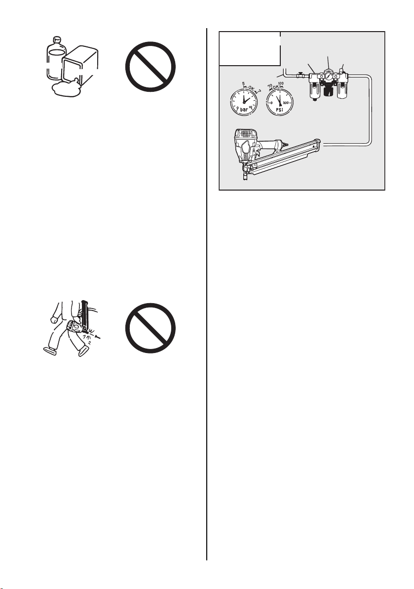
Aguarrás
Gasolina
[EL SUMINISTRO DE AIRE Y CONEXIONES]
Compresor de Aire
Aire Mangueras
Regulador
Filtro de Aire
Deposito de Acceite
NO UTILIZAR LA HERRAMIENTA CERCA DE
SUSTANCIAS INFLAMABLES
Nunca manejar herramienta cerca de sustancias
inflamables (por ejemplo, aguarrás, gasolina,
etc.). Gases volátiles de estas sustancias
pueden ser arrastradas dentro del compresor de
aire y el aire comprimido puede provocar una
explosión.
NO UTILIZAR ACCESORIOS IMPROPIOS
El conector de herramienta no debe contener
presión cuando el suministro de aire este
desconectado. Si se utiliza un accesorio
impropio, la herramienta puede quedarse
cargada con aire despuès de desconectar, de
este modo seguira funcionando incluso despuès
de haber desconectado el suministro de aire,
con la posibilidad de causar daños.
MIENTRAS LA HERRAMIENTA NO ESTE EN
USO, DESCONECTE LA ALIMENTACION DE
AIRE COMPRIMIDO Y VACIE EL CARGADOR
Siempre desconecte el suministro de aire desde
la herramienta y vacíe el cartucho, cuando la
operación ha sido completada o está
suspendida, cuando permanece sin atender,
cambiando a una área de trabajo diferente,
ajustando, desarmando o reparando la
herramienta, y al despejar un afianzador
atascado.
Conjunto de 3 piezas
Presión 70 a 100 p.s.i. (5 a 7 bar)
ACCESORIOS: Instalar un enchufe macho a la
herramienta, lo cual permite una corriente libre,
y suelta presión de la herramienta cuando se
desconecta de la fuente de suministro.
MANGUERAS: La manguera tiene un mínimo
de 1/4” (6 mm) y máximo de 17” (5 matros) de
largo.
Debe existir en la manguera un accesorio que
permite “desconectar rapido” del enchufe
macho.
FUENTE DE SUMINISTRO: Utilizar únicamente
aire comprimido regularizado limpio como fuente
de energía para la herramienta.
CONJUNTO DE 3 PIEZAS (Filtro de Aire,
Regulador, Deposito de Aceite):
Ver especificaciones de la herramienta para
ajustar la presión de operación adecuada para la
herramienta.
NOTA:
El uso de un filtro mejora el funcionamiento y
reduce el desgaste de la herramienta, ya que la
suciedad y el agua en el suministro de aire son
las causas principales del desgaste de la
herramienta.
Es necesario engrasar pero no excesivamente
para obtener un perfecto funcionamiento. El
aceite que se añade a la conexión de suministro
de aire engrasa las partes internas.
41
Page 42

4. INSTRUCCIONES PARA EL SERVICIO
LEA EL APARTADO CON EL TÍTULO
“INSTRUCCIONES PARA LA
SEGURIDAD”.
1. ANTES DE LA PUESTA EN SERVICIO
Verifique los puntos siguientes antes de utilizar
la herramienta.
1 Póngase gafas protectoras. 2 No conecte todavía el aire comprimido. 3 Compruebe los tornillos en cuanto a su firme
asiento.
4 Compruebe el funcionamiento del brazo de
contacto y la marcha fácil del disparador.
5 Conecte el aire comprimido. 6 Compruebe la herramienta en cuanto a
fugas de aire. (No deben existir fugas de
aire.)
7 Sujete la herramienta (sin colocar el dedo en
el disparador) y apriete el brazo de contacto
contra la pieza. (La herramienta no debe
funcionar.)
8 Mantenga la herramienta de modo que el
brazo de contacto no esté aplicado contra la
pieza, y accione el disparador. (La
herramienta no debe funcionar.)
9 Mientras la hirramienta no este en uso,
desconecte la alimentacion de aire
comprimido y vacie el cargador.
operador de herramienta y otro personal en el
área de trabajo.
OBSERVAR: Las gafas sin protección lateral y
sin blindaje de cara, no proporcionan la
protección adecuada.
ATENCIÓN
Durante el proceso de grapar/clavar, las manos
y el cuerpo deben mantenerse alejados del
orificio de salida ya que existe el riesgo de que
puedan ser heridos accidentalmente.
COLOCAR UN ROLLO DE CLAVOS
ATENCIÓN
•
Cuando se cargan los clavos, asegurarse
de quitar su dedo del gatillo.
•
No apretar el brazo de contacto contra el
objeto.
ATENCIÓN
2. SERVICIO
Utilizar gafas de seguridad. Debido a la
presencia de polvo en el aire, o el mal uso de la
herramienta, siempre existe peligro a los ojos.
Por estas razones, se deben utilizar siempre las
gafas de seguridad cuando se maneja la
herramienta. El usuario debe asegurarse de que
se emplea la protección adecuada. La
protección debe estar de acuerdo con los
requisitos de la “American National Standards
Institute, ANSI Z87.1”. Directiva del Consejo 89/
686/CEE del 21 de Diciembre de 1989 y debe
aportar protección frontal y lateral.
El empleador es responsable de implementar el
uso del equipo de protección de ojos para el
Clavos
MÉTODO
1 Cargar los clavos en la ranura en la parte del
cargador hasta que vayan sobre el bloque
de los clavos.
42
Bloque de los clavos
Page 43

Botón
2 Extraer el botón hasta el fondo del cargador,
luego liberarlo suavemente.
ATENCIÓN
Una liberación brusca del botón causará un
atasco de los clavos o un disparo a vacío.
PRUEBA DE FUNCIONAMIENTO
1 Ajuste la presión del aire a 70 p.s.i. (5 bares)
y conecte el aire comprimido.
2 Sin tocar el disparador, apriete el brazo de
contacto contra la pieza.
Accione el disparador. (La herramienta debe
disparar el clavo.)
3 Accione el disparador sin que la herramienta
esté aplicada contra la pieza.
A continuación, apriete el brazo de contacto
contra la pieza. (La herramienta debe
disparar el clavo.)
4 Ajustar la presión atmosférica a un nivel lo
más bajo posible, según la longitud del lazo
y la dureza de la pieza de trabajo.
SUJETADORES PARA
INTRODUCCIÓN
NOTA:
Esta herramienta se suministra con el modo de
ACCIONAMIENTO SIMPLE seleccionado.
ADVERTENCIA
•
Para evitar un disparo doble o accidental, tirar el disparador rápida y firmemente.
•
El ACCIONAMIENTO SIMPLE es diferente
del DISPARO SECUENCIAL.
•
La herramienta con ACCIONAMIENTO SIMPLE inserta un clavo cada vez que se inserta el brazo de contacto manteniendo al
mismo tiempo el dispositivo de disparo extraído, y cuando se tira el dispositivo de disparo y que se lo mantiene extraído después
de haber insertado el brazo de contacto.
ACCIONAMIENTO SIMPLE
Para el ACCIONAMIENTO SIMPLE, mantener
el dispositivo de disparo extraído e insertar el
brazo de contacto contra la superficie de trabajo,
o insertar el brazo de contacto contra la superficie de trabajo y tirar el dispositivo de disparo y
mantenerlo extraído. La herramienta no puede
extraer un segundo clavo hasta que el dispositivo de disparo esté liberado y la herramienta puede hacer un ciclo.
43
Page 44

CONMUTACIÓN DEL MODO DE ACCIONAMIENTO SIMPLE AL MODO DE
ACCIONAMIENTO DE CONTACTO
CON MECANISMO DE DISPARO ANTIDOBLE.
Perno de rodillo
Palanca de conmutación
Disparador
Punzón
ATENCIÓN
•
SIEMPRE desconecte la alimentación de
aire antes de cambiar el método de disparo.
1 Tirar suavemente la varilla de muelle que se
indica con la marca " T ", directamente con
el punzón u otra herramienta similar.
Varilla de muelle
2 Retirar la palanca de conmutación en la di-
rección de la flecha.
NOTA:
Cuando se vuelve a poner el DISPOSITIVO DE
DISPARO DE CONTACTO con el MECANISMO
DE DISPARO ANTIDOBLE en la posición DISPARO SIMPLE, ajustar la palanca de conmutación dirigida hacia la parte frontal de la marca “D”
con el pasador de resorte al dispositivo de disparo según el método opuesto.
44
Page 45

ATENCIÓN
•
Usar la palanca de conmutación de color metálico gris de acero de sinterización
Comprobar que la palanca de conmutación se especifica de origen cuando se aplica el método
de conmutación por atrás.
El uso de una palanca de conmutación distinta de la especificada de origen causará un accidente serio (ejemplo: Disparar los clavos impulsando simplemente el dispositivo de disparo, etc).
Color Forme (1/1 escala) Herramienta
METÁLICO GRIS ACERO
DE SINTERIZACIÓN
PLATA INOXIDABLE
ENNEGRECIMIENTO
DE ACERO
•
Nunca instalar la palanca de conmutación en el modelo anterior
NF550, SN883, y SN883
con disparador fino
SN883 y SN890 con dis-
parador grueso
HS90A
Esto causará accidentes serios. (por ejemplo, tirando clavos activando simplemente el disparador, etc)
Forma de proyección
Forma plana
Este modelo Otro modelo
45
Page 46

MODELO DE TRINQUETE DE CONTACTO con
MECANISMO de DISPARO ANTI-DOBLE
El mecanismo de disparo anti-doble (patente US
5597106, patente UK 2286790) está instalado
en esta herramienta. El procedimiento de
funcionamiento común en las herramientas de
“trinquete de contacto” es para que el operador
pueda entrar en contacto con la pieza de trabajo,
para actuar el mecanismo de trinquete, mientras
que se mantiene el disparador tirado,
accionando así un sujetador cada vez que se
entra en contacto con la pieza de trabajo. Esto
permitirá una colocación rápida del sujetador, en
muchos tipos de trabajos, tales como forro,
trabajos de puentes y montaje de plataforma.
Todas las herramientas neumáticas están
sujetadas a rebote, al clavar los sujetadores. La
herramienta puede rebotar, disparando el
trinquete, y si está contactando
involuntariamente otra vez la superficie de la
pieza de trabajo, con el disparador todavía
actuado (con su dedo todavía manteniendo el
disparador tirado), un segundo sujetador
indeseado será clavado.
OPERACIÓN DEL DISPANO DE CONTACTO
Para la operación del disparo de contacto,
mantener el disparador y presione el brazo del
contacto contra la superficie de la pieza de
trabajo.
OPERACIÓN SIMPLE DE DISPARO (MECANISMO DE DISPARO ANTI-DOBLE)
Para la operación simple de disparo, presione el
brazo del contacto contra la superficie de la pieza de trabajo y tire del disparador.
La herramienta no puede disparar un segundo
clavo, hasta que se libere el disparador y la herramienta puede girar.
2
1
PROCEDIMIENTO
1 Presione el brazo del contacto. 2 Tire del disparador.
IDENTIFICACION DE LOS MODELOS
Palanca de conmutación
1
2
PROCEDIMIENTO
1 Mantener el disparador. 2 Presione el brazo del contacto.
ACCIONAMIENTO SIMPLE
Definido por PALANCA DE CONMUTACIÓN.
MODELO DE TRINQUETE DE CONTACTO
con MECANISMO de DISPARO ANTI-DOBLE
(patente US 5597106, patente UK 2286790)
Visible por el DISPARADOR ROJO.
Se retira la palanca de conmutación.
46
Page 47

DISPARO SECUENCIAL
En caso de realizar un disparo secuencial, es necesario tocar la pieza con el aparato antes de apretar
la palanca de accionamiento. Esta técnica de disparo permite emplazar exactamente el clavo/la grapa
sin que exista la posibilidad de aplicar un segundo clavo/una segunda grapa con el retroceso del
apataro.
Los apatatos con disparo secuencial ofrecen las siguientes ventajas a nivel de seguridad: no se puede
producir un disparo accidental al tocar la pieza u otro objeto con el apataro, estando apretada la palanca
de accionamiento.
DISPARO SECUENCIAL
Visible por el DISPARADOR ANARANJADO.
PROCEDIMIENTO
1 Tirar el disparo y mantenerlo
tirado.
2 Presionar el brazo de contacto.
ACCIONAMIENTO
SIMPLE
• La herramienta dispara un clavo.
• La herramienta no puede disparar
un segundo clavo hasta que el
disparador esté liberado.
ACCIONAMIENTO DE
CONTACTO CON EL
MECANISMO DE
La herramienta dispara un clavo
cada vez que se presiona el brazo
de contacto.
DISPARO ANTIDOBLE
DISPARO SECUENCIAL La herramienta no puede disparar
un clavo.
1 Presionar el brazo de contacto. 2 Tirar el disparo y mantenerlo
tirado.
• La herramienta dispara un clavo.
• La herramienta no puede disparar
un segundo clavo hasta que el
disparador esté liberado.
• La herramienta dispara un clavo.
• La herramienta no puede disparar
un segundo clavo hasta que el
disparador esté liberado.
• La herramienta dispara un clavo.
• La herramienta no puede disparar
un segundo clavo hasta que el
disparador esté liberado y el
brazo de contacto se deja sobre
la superficie de trabajo.
47
Page 48
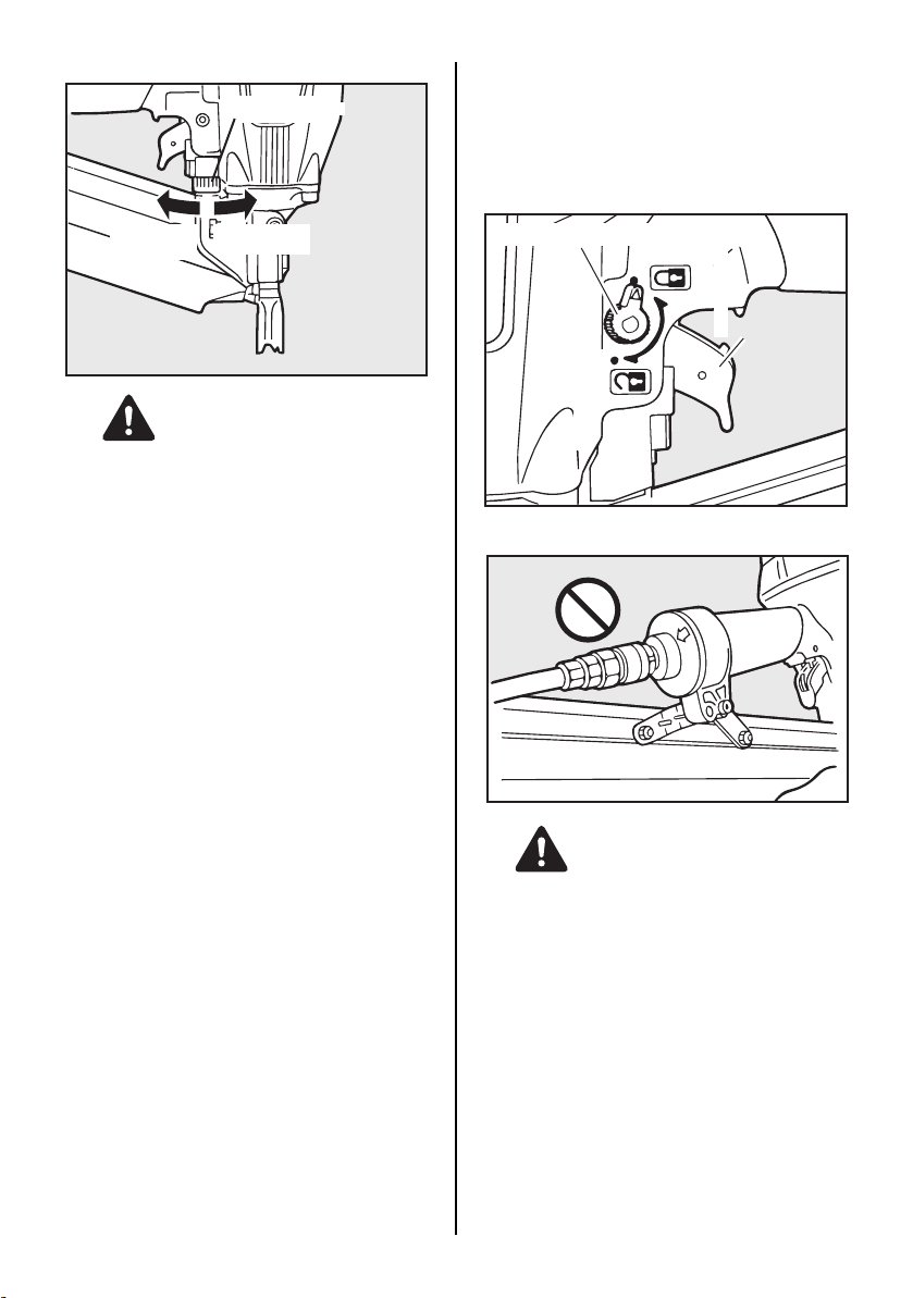
AJUSTE DE LA PROFUNDIDAD DE INSERCIÓN
Disco de ajuste
Mayor
profundidad
Menor
profundidad
EXPLICACION DEL MECANISMO DEL
BLOQUEO DEL GATILLO
La herramienta está equipada con un
mecanismo de blocaje del gatillo.
Empuje y gire el mecanismo de segure lad a la
posición lilre autes de clavar.
Blogueo de accionamiento
LOCK
(BLOQUEADO)
Disparador
UNLOCK
ATENCIÓN
SIEMPRE desconectar la alimentación de aire
antes de efectuar el ajuste.
El ajuste de profundidad de inserción se efectúa
ajustando el cuadrante de ajuste del brazo del
cuadrante de ajuste.
1 Con la presión de aira ajustada, insertar
algunos clavos en una muestra de material
típico para determinar si se debe efectuar el
ajuste.
2 Si el ajuste es necesario, desconectar la
alimentación de aire.
3 La marca en el brazo de contacto indica el
sentido en el cual se ha de girar el disco de
ajuste.
4 Conectar nuevamente la alimentación de
aire.
(DESBLOQUEADO)
CÓMO QUITAR LOS CLAVOS ATASCADOS
ATENCIÓN
SIEMPRE desconectar la alimentación de aire
antes de quitar los clavos atascados.
48
Page 49

Palanca del
empujador
MÉTODO
1 Empujar hacia abajo la palanca del
empujador y liberar los clavos a banda a
partir del empujador.
4 Retirar los clavos bloqueados de la Nariz
con un punzón o un destornillador a cabeza
de raja.
ATENCIÓN
Cuando extraiga el clavo bloqueado utilice
guantes.
No extraiga el clavo bloqueado con las manos
desnudas.
Imán
Bloque de clavos
2
Empujar el bloque de clavos, y retirar los clavos de banda a partir del interior del cargador.
Empujador
Clavos
remanentes
(SN883RH2 solamente)
ATENCIÓN
Los clavos se mantienen en la nariz de la
herramienta por medio del imán. (SN883RH2
solamente)
Esta herramienta se equipa de un imán en la
nariz para descargar todos los clavos instalados
en el cargador. Por lo tanto, si la banda de cotejo
es rota, hay clavos remanentes en la nariz,
aunque piensan que se han removido todos los
clavos. En ese caso, hay riesgo de accidente
serio si piensan que no hay ningún clavo
remanente y se activa la herramienta de
repente. Por esta razón, cuando se retiran los
clavos del cargador, confirmar que no hay
ningún clavo en la nariz, además del hecho de
que se desconectó el suministro del aire.
3 Extraer y volver a poner el empujador detrás
por medio del agujero y de la varilla.
49
Page 50
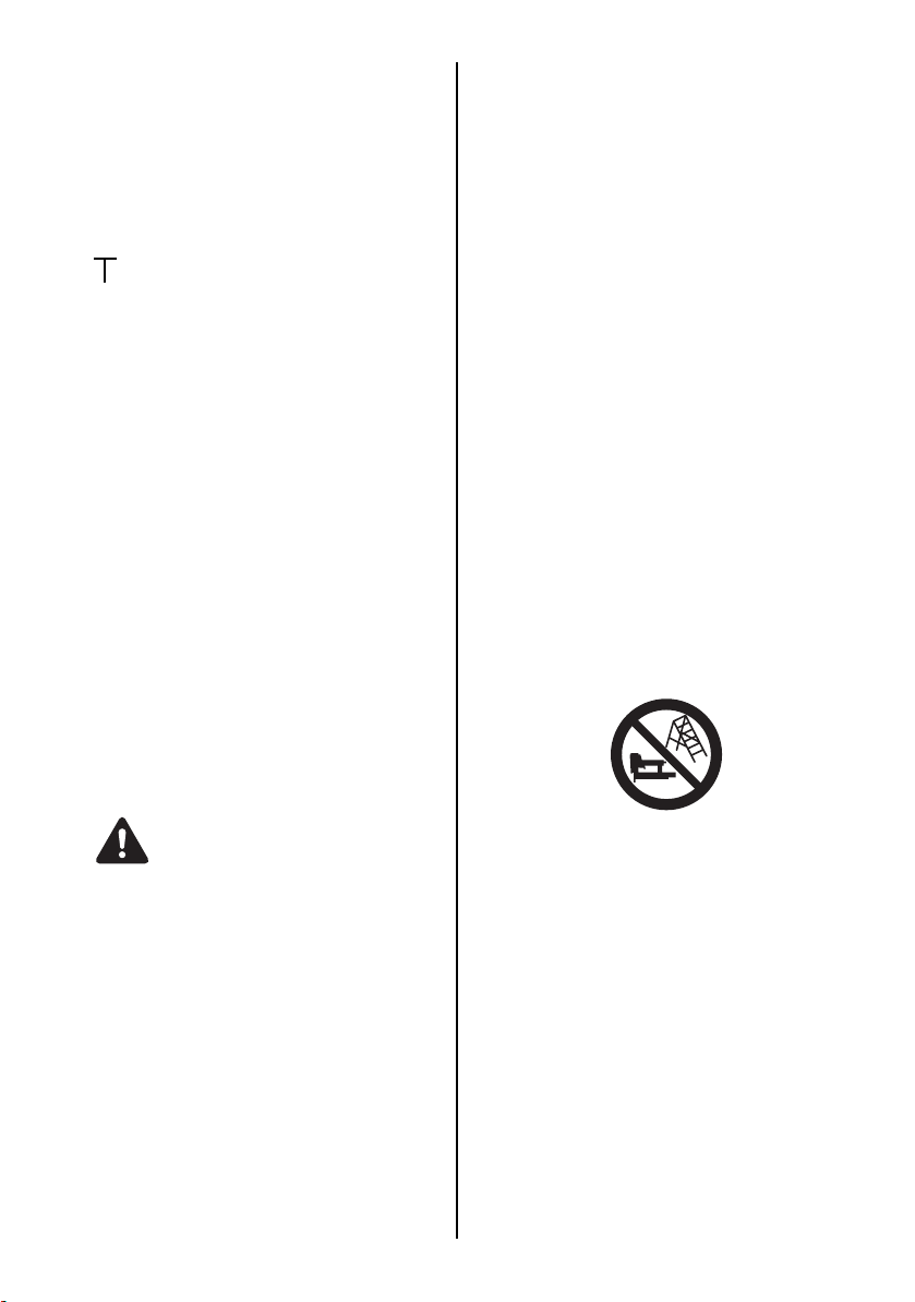
5. MANTENIMIENTO
1 ACERCA DEL AÑO DE PRODUCCIÓN
Este producto lleva el número de producción
en la parte inferior del apretón del cuerpo
principal. Los dos dígitos del número de la
izquierda indican el año de producción.
(Ejemplo)
0 8 8 2 6 0 3 5 D
Año 2008
2 NO DISPARE LA CLAVADORA CUANDO
ESTÉ VACÍA
3 UTILIZAR EL REGULADOR DE PRESIÓN
DE 3 PIEZAS
Si no se utiliza un regulador de presión la
humedad y suciedad pasa directamente a la
grapadora. Esto provoca oxidación y
desgaste y resultados poco favorables. La
longitud de la manguera entre el regulador y
la grapadora no debe sobrepasar 5 metros
ya que una medida mas larga reduce la
presión de aire.
4 UTILIZAR EL ACEITE RECOMENDADO
Se debe utilizar aceite turbina para engrasar
la herramienta. Cuando se completan las
operaciones echar dos o tres gotas de aceite
en la boquilla de entrada de la herramienta.
(ISO VG32)
5 PROCEDER A LA VERIFICACION Y A LA
MANUTENCION DE LA GRAPADORA O
CLAVADORA PERIODICAMENTE O
CADA VEZ QUE SE PONGA EN
FUNCIONAMIENTO
6. ALMACENAJE
1 Para evitar la formacion de oxido, aplicar
una capa de lubrificante sobre las partes
aceradas antes de reponer la misma para un
periodo prolongado.
2 No conservar la misma a temperaturas
bajas, sino en lugares calientes.
3 Cuando la misma no se utiliza, conservarla
en lugares calientes y secos. No tener la
grapadora o clavadora al alcance de los
niños.
4 Para que la grapadora o clavadora le de
siempre un resultado optimo, debera realizar
la manutencion y la sustitucion de las piezas
gastadas correctamente.
7. SUBSANACION DE AVERIAS
El diagnostico y/o las operaciones de reparacion
deben efectuarse exclusivamente por
concesionarios MAX CO. LTD. o por personal
especializado siguiendo las instrucciones
contenidas en el presente manual.
ATENCIÓN
Antes de proceder a la verificacion o a la
manutencion de la misma, interrumpir la
alimentacion de aire comprimido y vaciar el
cargador.
(1) Vaciar el filtro de la linea de aire y del
compresor.
(2) Mantener lleno el dispositivo de lubrificacion
presente en el set para aire comprimido
compuesto de tres elementos.
(3) Limpiar el elemento del filtro del sistema de
aire de 3 piezas
(4) Apretar todos los tornillos
(5) El brazo de contacto debe moverse
suavemente.
Suplemento a la instrucción para la operación
Según la Norma Europea EN792-13, la
regulación es válida desde el 1° de enero de
2001, que todas las herramientas para clavado
de sujetadores, con actuación de contacto, se
deben marcar con el símbolo “No utilice en
andamios y escalas”, y no deben ser utilizados
para un uso específico, por ejemplo:
∗ cuando el cambio de una posición de clavado
a otra implica el uso de andamios, escaleras,
escalas, o construcciones semejantes a
escala, e.g. listones de techo,
∗ cierre de cajas o cajones,
∗ instalación de sistemas de seguridad de
transporte e.g. en los vehículos y carros.
50
Page 51

SN883RH2
EXPLODED
VIEW AND SPARE PARTS LIST
SCHEMA ECLATE ET LISTE DES
PIECES DE RECHANGE
DESPIECE DE LA MAQUINA Y LISTA
DE RECAMBIOS
1
2
3
4
6
7
8
9
10
9
11
12
13
14
15
16
17
18
19
20
5
22
82
81
89
32
33
34
35
36
87
37
38
39
40
41
42
44
47
49
51
52
54
57
58
55
60
61
64
21
28
29
30
31
201
67
43
90
45
46
48
50
72
78
202
53
55
58
59
80
62
63
65
23
83
70
27
OPTION
O-RING KIT
Part s mar ked
the O-ring kit
203
207
75
6
79
208
28
are
inincluded
24
91
25
204
69
206
27
72
84
77
27
86
85
70
32
33
101
35
102
103
26
38
39
104
105
106
107
47
108
109
70
73
92
76
55
113
29
30
31
110
43
111
50
66
68
70
27
74
71
115
51
Page 52

SN883RH2
ITEM
PAR T
NO.
1
KN12666
2
KN12678
3
KN12194
4
KN12669
5
KN70168
6
KN12653
7
KN12627
8
KN12656
9
KN12650
10
KN12645
11
KN70142
12
KN12613
13
KN70170
14
KN12628
15
KN12190
16
KN12649
17
KN12648
18
KN12634
19
KN12614
20
KN12193
21
KN81069
22
KN12205
23
KN12206
24
KN12671
25
CN35685
26
KN12436
27
EE31121
28
KN12643
29
KN12644
30
KN12636
31
KN12660
32
KN12642
33
KN12646
34
KN12664
35
KN12641
36
KN12654
37
KN12658
38
KN12647
39
KN12637
40
KN12635
41
KN12630
42
KN12401
43
FF22402
44
HS10145
45
KN12620
46
CN34500
47
KK23129
48
KN23943
49
KN12207
50
KN12618
51
KN12212
52
KN12651
53
KN12200
54
KN70172
55
KN12668
56
57
KN12670
58
KN12619
59
KN12617
NO.
Steel
Rubber
Steel
Steel
Aluminum
Stainless steel
Urethane
Aluminum
Rubber
Rubber
Stainless steel, Rubber
Rubber
Magnesium, Steel
Urethane
Polyacetal
Rubber
Rubber
Aluminum
Rubber
Rubber
Aluminum
Aluminum
Aluminum
Steel
Nylon
Aluminum
Steel
Rubber
Rubber
Polyacetal
Stainless steel
Rubber
Rubber
Polyacetal
Rubber
Stainless steel
Steel
Rubber
Polyacetal
Steel
Steel
Polyacetal
Stainless steel
Nylon
Steel
Stainless steel
Stainless steel
Stainless steel
Nylon
Rubber
Steel
Rubber
Polyacetal
Steel
Steel
Steel
Steel
Rubber
SCREW 5X12 VIS 5X12 TORNILLO 5X12
ESPAÑOLFRANÇAISENGLISHMATERIAL
EXHAUST GUIDE FILTRE ECHAPPEMENT FILTRO DE ESCAPE
EXHAUST COVER CAPOT D'ASPIRATION CAMPANA DE ASPIRACIÓN
SCREW 6X28 VIS 6X28 TORNILLO 6X28
CYLINDER CAP UNIT COUVERCLE DE CYLINDRE COMPLET CUBIERTA DE CILINDRO COMPL.
COMPRESSION SPRING 2653 RESSORT À PRESSION 2653 MUELLE DE COMPRESIÓN 2653
PISTON STOP BUTÉE DE PISTON TOPE EMBOLO
HEAD VALVE PISTON PISTON DE CLAPET DE TÉTE EMBOLO VÁLVULA DEL CABEZAL
O-RING AS568-150 JOINT TORIQUE AS568-150 ANILLO TÓRICO AS568-150
O-RING AS568-142 JOINT TORIQUE AS568-142 ANILLO TÓRICO AS568-142
CYLINDER CAP SEAL UNIT
O-RING 4.5X48.8 JOINT TORIQUE 4.5X48.8 ANILLO TÓRICO 4.5X48.8
MAIN PISTON UNIT PISTON DE TRAVAIL COMPLET EMBOLO DE TRAVAJO COMPL.
CYLINDER SEAL RONDELLE DE CYLINDRE ARANDELA DE CILINDRO
CYLINDER RING JOINT DE CYLINDRE ANILLO DE CILINDRO
O-RING 1AG100 JOINT TORIQUE 1AG100 ANILLO TÓRICO 1AG100
O-RING 1AG70 JOINT TORIQUE 1AG70 ANILLO TÓRICO 1AG70
CYLINDER CYLINDRE CILINDRO
CHECK PAWL CLIQUET D'ARRÊT TRINQUETE
BUMPER AMORTISSEUR AMORTIGUADOR
FRAME BOÎTIER CARCASA
NAME LABEL A JOINT DE NOM A JUNTA DE NOMBRE A
NAME LABEL B JOINT DE NOM B JUNTA DE NOMBRE B
SCREW 5X28 VIS 5X28 TORNILLO 5X28
END CAP FILTER SA-10
END CAP CAPOT DE RECOUVREMENT CAPERUZA DE CIERRE
PLANE WASHER 1-5 RONDELLE LISSE 1-5 ARANDELA LISA 1-5
O-RING 1AP12 JOINT TORIQUE 1AP12 ANILLO TÓRICO 1AP12
O-RING 1AP20 JOINT TORIQUE 1AP20 ANILLO TÓRICO 1AP20
TRIGGER VALVE HOUSING
PARALLEL PIN 2660 GOUPILLE PARALLELE 2660 PERNO PARALELO 2660
O-RING 1AP6 JOINT TORIQUE 1AP6 ANILLO TÓRICO 1AP6
O-RING 1BP7 JOINT TORIQUE 1BP7 ANILLO TÓRICO 1BP7
PILOT VALVE VANNE-PILOTE VÁLVULA DE CONTROL
O-RING 1AP9 JOINT TORIQUE 1AP9 ANILLO TÓRICO 1AP9
COMPRESSION SPRING 2654 RESSORT À PRESSION 2654 MUELLE DE COMPRESIÓN 2654
TRIGGER VALVE STEM TIGE DE SOUPAPE DE COMMANDE VÁSTAGO VÁLVULA DE ACCIONAMIENTO
O-RING 1B 1.4X2.5 JOINT TORIQUE 1B 1.4X2.5 ANILLO TÓRICO 1B 1.4X2.5
TRIGGER VALVE CAP CAPUCHON DE SOUPAPE DE COMMANDE CAPERUZA VÁLVULA DE ACCIONAMIENTO
CONTCT LEVER B LEVIER DE CONTACT B PALANCA DE CONTACTO B
CONTCT LEVER A LEVIER DE CONTACT A PALANCA DE CONTACTO A
TRIGGER LEVIER DE COMMANDE PALANCA DE ACCIONAMIENTO
ROLL PIN 3X16 TOURILLON DE CYLINDRE 3X16 PERNO DE RODILLO 3X16
SWITCH LEVER A LEVIER D'INTERRUPTEUR A PALANCA DEL INTERRUPTOR A
SWITCH LEVER B LEVIER D'INTERRUPTEUR B PALANCA DEL INTERRUPTOR B
SWITCH SPRING RESSORT D'INTERRUPTEUR MUELLE DEL INTERRUPTOR
COMPRESSION SPRING 3129 RESSORT À PRESSION 3129 MUELLE DE COMPRESIÓN 3129
COMPRESSION SPRING 3943 RESSORT À PRESSION 3943 MUELLE DE COMPRESIÓN 3943
ARM GUIDE GUIDE DE BRAS DE CONTACT GUÍA DEL BRAZO
EXHAUST SEAL RONDELLE ECHAPPEMENT ARANDELA DE ESCAPE
CONTACT ARM A BARRE DE CONTACT A BRAZO DE CONTACTO A
O-RING AS568-144 JOINT TORIQUE AS568-144 ANILLO TÓRICO AS568-144
ADJUST DIAL CADRAN DE RÉGLAGE CUADRANTE DE AJUSTE
NOSE UNIT NEZ DU CLOUEUR COMPLET PICO DEL CLAVADORCOMPL.
SCREW 5X10 VIS 5X10 TORNILLO 5X10
SCREW 8X28 VIS 8X28 TORNILLO 8X28
PLANE WASHER 5.1X12X1.2 RONDELLE LISSE 5.1X12X1.2 ARANDELA LISA 5.1X12X1.2
MAGAZINE GUIDE B GUIDE DE MAGASIN B GUÎA DE CARGADOR B
UNITE DE RONDELLE DE COUVERCLE DE CYLINDRE COMPL. DE CUBIERTA DE ARANDELA DE CILINDRO
FILTRE SA-10 DE CAPOT DE RECOUVREMENT FILTRO DEL CAPPUCCIO DI CHIUSURA SA-10
CARTER DE SOUPAPE DE DÉCLENCHEMENT
CUBIERTA DE VÁLVULA DEL DISPARADOR
52
Page 53

SN883RH2
ITEM
PART
NO.
60
KN12616
61
KK23694
62
KN12215
63
KN12652
64
KN70171
65
KN12672
66
KN12624
67
KN12663
68
KN12629
69
KN12203
70
CC49411
71
KN12623
72
KN12667
73
KN12419
74
KN81068
75
GN12070
76
KN12640
77
KN12661
78
KN12625
79
KN12633
80
KN12662
81
KN12622
82
KK23507
83
KN12621
84
KN12626
85
KN12204
86
CN31083
87
KN12655
88
89
FF21235
90
KN12615
91
HH12111
92
KN12420
101
CN32246
102
KK24123
103
CN35128
104
HN10100
105
HS10118
106
HN10786
107
KN12277
108
KN12278
109
KN12276
110
KK33300
111
KK23973
113
KN12405
115
BB40027
201
KN81070
202
KN81071
203
KN81074
204
KN81027
206
4009561
207
4009560
208
KN81035
NO.
Rubber
Stainless steel
Steel
Rubber
Steel
Stainless steel
Polyacetal
Stainless steel
Stainless steel
Steel
Steel, Nylon
Nylon
Steel
Stainless steel
Aluminum
Steel
Stainless steel
Stainless steel
Nylon
Steel
Steel
Nylon
Stainless steel
Nylon
Polyacetal
Nylon
Rubber
Stainless steel
Steel
Steel
Rubber
Stainless steel
Polyacetal
Stainless steel
Steel
Steel
Polyacetal
Stainless steel
Steel
Nylon
Steel
Stainless steel
Stainless steel
Steel, Stainless steel
Steel
PET
PET
ESPAÑOLFRANÇAISENGLISHMATERIAL
MAGAZINE GUIDE A GUIDE DE MAGASIN A GUÍA DE CARGADOR A
COMPRESSION SPRING 3964 RESSORT Á PRESSION 3964 MUELLE DE COMPRESIÓN 3964
CONTACT BOLT BOULON DE CONTACT PERNO DE CONTACTO
O-RING 1A 1x6.2 JOINT TORIQUE 1A 1x6.2 ANILLO TÓRICO 1A 1x6.2
CONTACT ARM B UNIT BARRE DE CONTACT B BRAZO DE CONTACTO B
E-RETAINING RING 5 BAGUE DE RETENUE E 5 ANILLO DE RETENCIÓN EN E 5
NAIL GUIDE B GUIDE DE CLOUS B GUÍA DE CLAVOS B
NAIL GUIDE A GUIDE DE CLOUS A GUÍA DE CLAVOS A
NAIL COVER COUVERCLE DE CLOUS CUBIERTA DE CLAVOS
TAIL HANGER SUPPORT DE QUEUE SOPORTE DE COLA
NUT M5 ECROU M5 TUERCA M5
TAIL COVER COUVERCLE DE QUEUE CUBIERTA DE COLA
SCREW 5X14 VIS 5X14 TORNILLO 5X14
NAIL STOPPER PIECE ARRET DE CLOUS TOPE DE CLAVOS
MAGAZINE MAGASIN CARGADOR
RUBBER WASHER 1.8x6x2 DISQUE DE CAOUTCHOUC 1.8x6x2 ARANDELA DE CAUCHO 1.8x6x2
SPIRAL SPRING 2640 RESSORT SPIRAL 2640 MUELLE ESPIRAL 2640
PARALLEL PIN 2661 GOUPILLE PARALLELE 2661 PERNO PARALELO 2661
PUSHER HOLDER SUPPORT DE POUSSOIR SOPORTE DE EMPUJADOR
PUSHER POUSSOIR EMPUJADOR
PARALLEL PIN 2662 GOUPILLE PARALLELE 2662 PERNO PARALELO 2662
TRIGGER LOCK LEVER LEVIER DE BLOCAGE DE LA COMMANDE PALANCA, BLOQUEO DE ACCIONAMIENTO
COMPRESSION SPRING 3507 RESSORT Á PRESSION 3507 MUELLE DE COMPRESIÓN 3507
TRIGGER LOCK DIAL DISQUE DE BLOCAGE DE LA COMMANDE DISCO, BLOQUE DE ACCIONAMIENTO
SPRING COLLAR COLLIER DE RESSORT COLLAR DE MUELLE
ARM COVER COUVERCLE DE BRAS CUBIERTA DEL BRAZO
DUST COVER HOOK
COMPRESSION SPRING 2655 RESSORT Á PRESSION 2655 MUELLE DE COMPRESIÓN 2655
ROLL PIN 3X30 TOURILLON DE CYLINDRE 3X30 PERNO DE RODILLO 3X30
SWITCHING LEVER LEVIER DE COMMUTATION PALANCA DE CONMUTACIÓN
O-RING 1AG45 JOINT TORIQUE 1AG45 ANILLO TÓRICO 1AG45
NAIL STOPPER B PIECE ARRET DE CLOUS B TOPE DE CLAVOS B
PILOT VALVE VANNE-PILOTE VÁLVULA DE CONTROL
COMPRESSION SPRING 4123 RESSORT À PRESSION 4123 MUELLE DE COMPRESIÓN 4123
TRIGGER VALVE STEM TIGE DE SOUPAPE DE COMMANDE VÁSTAGO VÁLVULA DE ACCIONAMIENTO
CONTACT LEVER LEVIER DE CONTACT PALANCA DE CONTACTO
TRIGGER LEVIER DE COMMANDE PALANCA DE ACCIONAMIENTO
ARM GUIDE PLATE PLAQUE DE GUIDE DE BRAS PLACA DE GUÍA DEL BRAZO
CONTACT ARM A GUIDE GUIDE DE BRAS DE CONTACT A GUÍA DEL BRAZO DE CONTACTO A
ARM GUIDE GUIDE DE BRAS DE CONTACT GUÍA DEL BRAZO
CONTACT ARM A BARRE DE CONTACT A BRAZO DE CONTACTO A
TORSION SPRING 3300 RESSORT DE TORSION 3300 MUELLE DE TORSIÓN 3300
COMPRESSION SPRING 3973 RESSORT Á PRESSION 3973 MUELLE DE COMPRESIÓN 3973
RAFTER HOOK CROCHET DE COMBLE GANCHO DE CIMA
SCREW 5X30 VIS 5X30 TORNILLO 5X30
TRIGGER VALVE KIT KIT DE SOUPAPE DE COMMANDE KIT VÁLVULA DE ACCIONAMIENTO
ARM GUIDE KIT KIT DE GUIDE DE BRAS KIT DE LA GUÍA DEL BRAZO
O-RING KIT KIT DE JOINT TORIQUE KIT DE ANILLO TÓRICO
SEQUENTIAL TRIP KIT KIT DE DÉCLENCHEMENT SÉQUENTIEL KIT DE DISPARO SECUENCIAL
NAME LABEL JOINT DE NOM JUNTA DE NOMBRE
CAUTION LABEL ÉTIQUETTE DE PRÉCAUTION ETIQUETA DE PRECAUCIÓN
RAFTER HOOK KIT KIT DE CROCHET DE COMBLE EQUIPO DE GANCHO DE CIMA
CROCHET DE COUVERCLE ANTI-POUSSIÈRE
GANCHO DE LA TAPA GUARDAPOLVO
53
Page 54

SN890CH2<34>
211
OPTION
EXPLODED
1
3
4
112
7
8
9
10
9
11
12
13
14
15
16
17
18
19
20
2
5
22
82
81
47
VIEW AND SPARE PARTS LIST
SCHEMA ECLATE ET LISTE DES
PIECES DE RECHANGE
21
23
83
28
89
32
33
34
35
36
87
37
38
39
40
41
42
49
51
52
54
57
58
55
60
61
64
29
30
70
31
201
90
50
45
46
202
67
72
78
53
55
58
59
80
62
63
65
43
44
48
DESPIECE DE LA MAQUINA Y LISTA
DE RECAMBIOS
O-RING KIT
Parts mar ked
are
inincluded
207
27
75
79
27
208
OPTION
the O-ring kit
203
24
25
69
84
77
6
85
56
213
76
86
70
204
206
27
55
26
210
32
33
101
35
102
103
38
39
104
105
106
107
47
108
109
68
70
74
73
113
28
29
30
31
110
43
111
50
66
212
70
71
27
115
54
Page 55

SN890CH2<34>
ITEM
PAR T
NO.
NO.
1
KN12666
2
KN12678
3
KN12194
4
KN12669
5
KN70168
6
KN12720
7
KN12627
8
KN12656
9
KN12650
10
KN12645
11
KN70142
12
KN12613
13
KN70175
14
KN12628
15
KN12190
16
KN12649
17
KN12648
18
KN12634
19
KN12614
20
KN12193
21
KN81069
22
KN12205
23
KN12206
24
KN12671
25
CN35685
26
KN12436
27
EE31121
28
KN12643
29
KN12644
30
KN12636
31
KN12660
32
KN12642
33
KN12646
34
KN12664
35
KN12641
36
KN12654
37
KN12658
38
KN12647
39
KN12637
40
KN12635
41
KN12630
42
KN12401
43
FF22402
44
HS10145
45
KN12620
46
CN34500
47
KK23129
48
KK29025
49
KN12207
50
KN12618
51
KN12212
52
KN12651
53
KN12200
54
KN12711
55
KN12668
56
HH12111
57
KN12670
58
KN12619
59
KN12717
Steel
Rubber
Steel
Steel
Aluminum
Stainless steel
Urethane
Aluminum
Rubber
Rubber
Stainless steel, Rubber
Rubber
Magnesium, Steel
Urethane
Polyacetal
Rubber
Rubber
Aluminum
Rubber
Rubber
Aluminum
Aluminum
Aluminum
Steel
Nylon
Aluminum
Steel
Rubber
Rubber
Polyacetal
Stainless steel
Rubber
Rubber
Polyacetal
Rubber
Stainless steel
Steel
Rubber
Polyacetal
Steel
Steel
Polyacetal
Stainless steel
Nylon
Steel
Stainless steel
Stainless steel
Stainless steel
Nylon
Rubber
Steel
Rubber
Polyacetal
Steel
Steel
Rubber
Steel
Steel
Rubber
ESPAÑOLFRANÇAISENGLISHMATERIAL
SCREW 5X12 VIS 5X12 TORNILLO 5X12
EXHAUST GUIDE FILTRE D'ÉCHAPPEMENT GUÍA DE ESCAPE
EXHAUST COVER CAPOT D'ASPIRATION CAMPANA DE ASPIRACIÓN
SCREW 6X28 VIS 6X28 TORNILLO 6X28
CYLINDER CAP UNIT COUVERCLE DE CYLINDRE COMPLET CUBIERTA DE CILINDRO COMPL.
COMPRESSION SPRING 2720 RESSORT À PRESSION 2720 MUELLE DE COMPRESIÓN 2720
PISTON STOP BUTÉE DE PISTON TOPE EMBOLO
HEAD VALVE PISTON PISTON DE CLAPET DE TÉTE EMBOLO VÁLVULA DEL CABEZAL
O-RING AS568-150 JOINT TORIQUE AS568-150 ANILLO TÓRICO AS568-150
O-RING AS568-142 JOINT TORIQUE AS568-142 ANILLO TÓRICO AS568-142
CYLINDER CAP SEAL UNIT
O-RING 4.5X48.8 JOINT TORIQUE 4.5X48.8 ANILLO TÓRICO 4.5X48.8
MAIN PISTON UNIT PISTON DE TRAVAIL COMPLET EMBOLO DE TRAVAJO COMPL.
CYLINDER SEAL RONDELLE DE CYLINDRE ARANDELA DE CILINDRO
CYLINDER RING JOINT DE CYLINDRE ANILLO DE CILINDRO
O-RING 1AG100 JOINT TORIQUE 1AG100 ANILLO TÓRICO 1AG100
O-RING 1AG70 JOINT TORIQUE 1AG70 ANILLO TÓRICO 1AG70
CYLINDER CYLINDRE CILINDRO
CHECK PAWL CLIQUET D'ARRÊT TRINQUETE
BUMPER AMORTISSEUR AMORTIGUADOR
FRAME BOÎTIER CARCASA
NAME LABEL A JOINT DE NOM A JUNTA DE NOMBRE A
NAME LABEL B JOINT DE NOM B JUNTA DE NOMBRE B
SCREW 5X28 VIS 5X28 TORNILLO 5X28
END CAP FILTER SA-10
END CAP CAPOT DE RECOUVREMENT CAPERUZA DE CIERRE
PLANE WASHER 1-5 RONDELLE LISSE 1-5 ARANDELA LISA 1-5
O-RING 1AP12 JOINT TORIQUE 1AP12 ANILLO TÓRICO 1AP12
O-RING 1AP20 JOINT TORIQUE 1AP20 ANILLO TÓRICO 1AP20
TRIGGER VALVE HOUSING
PARALLEL PIN 2660 GOUPILLE PARALLELE 2660 PERNO PARALELO 2660
O-RING 1AP6 JOINT TORIQUE 1AP6 ANILLO TÓRICO 1AP6
O-RING 1BP7 JOINT TORIQUE 1BP7 ANILLO TÓRICO 1BP7
PILOT VALVE VANNE-PILOTE VÁLVULA DE CONTROL
O-RING 1AP9 JOINT TORIQUE 1AP9 ANILLO TÓRICO 1AP9
COMPRESSION SPRING 2654 RESSORT À PRESSION 2654 MUELLE DE COMPRESIÓN 2654
TRIGGER VALVE STEM TIGE DE SOUPAPE DE COMMANDE VÁSTAGO VÁLVULA DE ACCIONAMIENTO
O-RING 1B 1.4X2.5 JOINT TORIQUE 1B 1.4X2.5 ANILLO TÓRICO 1B 1.4X2.5
TRIGGER VALVE CAP CAPUCHON DE SOUPAPE DE COMMANDE CAPERUZA VÁLVULA DE ACCIONAMIENTO
CONTCT LEVER B LEVIER DE CONTACT B PALANCA DE CONTACTO B
CONTCT LEVER A LEVIER DE CONTACT A PALANCA DE CONTACTO A
TRIGGER LEVIER DE COMMANDE PALANCA DE ACCIONAMIENTO
ROLL PIN 3X16 TOURILLON DE CYLINDRE 3X16 PERNO DE RODILLO 3X16
SWITCH LEVER A LEVIER D'INTERRUPTEUR A PALANCA DEL INTERRUPTOR A
SWITCH LEVER B LEVIER D'INTERRUPTEUR B PALANCA DEL INTERRUPTOR B
SWITCH SPRING RESSORT D'INTERRUPTEUR MUELLE DEL INTERRUPTOR
COMPRESSION SPRING 3129 RESSORT À PRESSION 3129 MUELLE DE COMPRESIÓN 3129
COMPRESSION SPRING 9025 RESSORT À PRESSION 9025 MUELLE DE COMPRESIÓN 9025
ARM GUIDE GUIDE DE BRAS DE CONTACT GUÍA DEL BRAZO
EXHAUST SEAL RONDELLE ECHAPPEMENT ARANDELA DE ESCAPE
CONTACT ARM A BARRE DE CONTACT A BRAZO DE CONTACTO A
O-RING AS568-144 JOINT TORIQUE AS568-144 ANILLO TÓRICO AS568-144
ADJUST DIAL CADRAN DE RÉGLAGE CUADRANTE DE AJUSTE
NOSE NEZ DE CLOUEUR NARIZ
SCREW 5X10 VIS 5X10 TORNILLO 5X10
O-RING 1AG45 JOINT TORIQUE 1AG45 ANILLO TÓRICO 1AG45
SCREW 8X28 VIS 8X28 TORNILLO 8X28
PLANE WASHER 5.1X12X1.2 RONDELLE LISSE 5.1X12X1.2 ARANDELA LISA 5.1X12X1.2
MAGAZINE GUIDE B GUIDE DE MAGASIN B GUÎA DE CARGADOR B
UNITE DE RONDELLE DE COUVERCLE DE CYLINDRE
FILTRE SA-10 DE CAPOT DE RECOUVREMENT FILTRO DEL CAPPUCCIO DI CHIUSURA SA-10
CARTER DE SOUPAPE DE DÉCLENCHEMENT
COMPL. DE CUBIERTA DE ARANDELA DE CILINDRO
CUBIERTA DE VÁLVULA DEL DISPARADOR
55
Page 56

SN890CH2<34>
ITEM
PAR T
NO.
NO.
60
KN12616
61
KK29024
62
KN12590
63
KN12652
64
KN70171
65
KN12672
66
KN12624
67
KN12722
68
KN12716
69
KN12574
70
CC49411
71
KN12715
72
KN12667
73
KN12419
74
KN81072
75
GN12070
76
KN12719
77
KN12661
78
KN12714
79
KN12712
80
KN12662
81
KN12622
82
KK23507
83
KN12621
84
KN12723
85
KN12573
86
CN31083
87
KN12655
89
FF21235
90
KN12615
91
KN12420
101
CN32246
102
KK24123
103
CN35128
104
HN10100
105
HS10118
106
HN10786
107
KN12277
108
KN12278
109
KN12276
110
KK33300
111
KK23973
112
KN12653
113
KN12405
115
BB40027
201
KN81070
202
KN81073
203
KN81074
204
KN81027
206
4009565
207
4009564
208
KN81035
210
KN12420
211
KN81054
212
KN12676
213
BB40404
Rubber
Stainless steel
Steel
Rubber
Steel
Stainless steel
Polyacetal
Stainless steel
Stainless steel
Steel
Steel, Nylon
Nylon
Steel
Stainless steel
Aluminum
Steel
Stainless steel
Stainless steel
Nylon
Steel
Steel
Nylon
Stainless steel
Nylon
Polyacetal
Nylon
Rubber
Stainless steel
Steel
Stainless steel
Stainless steel
Polyacetal
Stainless steel
Steel
Steel
Polyacetal
Stainless steel
Steel
Nylon
Steel
Stainless steel
Stainless steel
Stainless steel
Steel, Stainless steel
Steel
Polyethylene terephthalate
Polyethylene terephthalate
Stainless steel
Steel
MAGAZINE GUIDE A GUIDE DE MAGASIN A GUÍA DE CARGADOR A
COMPRESSION SPRING RESSORT Á PRESSION MUELLE DE COMPRESIÓN
CONTACT BOLT BOULON DE CONTACT PERNO DE CONTACTO
O-RING 1A 1.5x5 JOINT TORIQUE 1A 1.5x5 ANILLO TÓRICO 1A 1.5x5
CONTACT ARM B UNIT BARRE DE CONTACT B BRAZO DE CONTACTO B
E-RETAINING RING 5 BAGUE DE RETENUE E 5 ANILLO DE RETENCIÓN EN E 5
NAIL GUIDE B GUIDE DE CLOUS B GUÍA DE CLAVOS B
NAIL GUIDE A GUIDE DE CLOUS A GUÍA DE CLAVOS A
NAIL COVER COUVERCLE DE CLOUS CUBIERTA DE CLAVOS
TAIL HANGER SUPPORT DE QUEUE SOPORTE DE COLA
NUT M5 ECROU M5 TUERCA M5
TAIL COVER COUVERCLE DE QUEUE CUBIERTA DE COLA
SCREW 5X14 VIS 5X14 TORNILLO 5X14
NAIL STOPPER PIECE ARRET DE CLOUS TOPE DE CLAVOS
MAGAZINE MAGASIN CARGADOR
RUBBER WASHER 1.8x6x2 DISQUE DE CAOUTCHOUC 1.8x6x2 ARANDELA DE CAUCHO 1.8x6x2
SPIRAL SPRING 2719 RESSORT SPIRAL 2719 MUELLE ESPIRAL 2719
PARALLEL PIN 2661 GOUPILLE PARALLELE 2661 PERNO PARALELO 2661
PUSHER HOLDER SUPPORT DE POUSSOIR SOPORTE DE EMPUJADOR
PUSHER POUSSOIR EMPUJADOR
PARALLEL PIN 2662 GOUPILLE PARALLELE 2662 PERNO PARALELO 2662
TRIGGER LOCK LEVER LEVIER DE BLOCAGE DE LA COMMANDE PALANCA, BLOQUEO DE ACCIONAMIENTO
COMPRESSION SPRING 3507 RESSORT Á PRESSION 3507 MUELLE DE COMPRESIÓN 3507
TRIGGER LOCK DIAL DISQUE DE BLOCAGE DE LA COMMANDE DISCO, BLOQUE DE ACCIONAMIENTO
SPRING COLLAR COLLIER DE RESSORT COLLAR DE MUELLE
ARM COVER COUVERCLE DE BRAS CUBIERTA DEL BRAZO
DUST COVER HOOK
COMPRESSION SPRING 2655 RESSORT Á PRESSION 2655 MUELLE DE COMPRESIÓN 2655
ROLL PIN 3X30 TOURILLON DE CYLINDRE 3X30 PERNO DE RODILLO 3X30
SWITCHING LEVER LEVIER DE COMMUTATION PALANCA DE CONMUTACIÓN
NAIL STOPPER B PIECE ARRET DE CLOUS B TOPE DE CLAVOS B
PILOT VALVE VANNE-PILOTE VÁLVULA DE CONTROL
COMPRESSION SPRING 4123 RESSORT À PRESSION 4123 MUELLE DE COMPRESIÓN 4123
TRIGGER VALVE STEM TIGE DE SOUPAPE DE COMMANDE VÁSTAGO VÁLVULA DE ACCIONAMIENTO
CONTACT LEVER LEVIER DE CONTACT PALANCA DE CONTACTO
TRIGGER LEVIER DE COMMANDE PALANCA DE ACCIONAMIENTO
ARM GUIDE PLATE PLAQUE DE GUIDE DE BRAS PLACA DE GUÍA DEL BRAZO
CONTACT ARM A GUIDE GUIDE DE BRAS DE CONTACT A GUÍA DEL BRAZO DE CONTACTO A
ARM GUIDE GUIDE DE BRAS DE CONTACT GUÍA DEL BRAZO
CONTACT ARM A BARRE DE CONTACT A BRAZO DE CONTACTO A
TORSION SPRING 3300 RESSORT DE TORSION 3300 MUELLE DE TORSIÓN 3300
COMPRESSION SPRING 3973 RESSORT Á PRESSION 3973 MUELLE DE COMPRESIÓN 3973
COMPRESSION SPRING 2653 RESSORT Á PRESSION 2653 MUELLE DE COMPRESIÓN 2653
RAFTER HOOK CROCHET DE COMBLE GANCHO DE CIMA
SCREW 5X30 VIS 5X30 TORNILLO 5X30
TRIGGER VALVE KIT KIT DE SOUPAPE DE COMMANDE KIT VÁLVULA DE ACCIONAMIENTO
ARM GUIDE KIT KIT DE GUIDE DE BRAS KIT DE LA GUÍA DEL BRAZO
O-RING KIT KIT DE JOINT TORIQUE KIT DE ANILLO TÓRICO
SEQUENTIAL TRIP KIT KIT DE DÉCLENCHEMENT SÉQUENTIEL KIT DE DISPARO SECUENCIAL
NAME LABEL JOINT DE NOM JUNTA DE NOMBRE
CAUTION LABEL ÉTIQUETTE DE PRÉCAUTION ETIQUETA DE PRECAUCIÓN
RAFTER HOOK KIT KIT DE CROCHET DE COMBLE EQUIPO DE GANCHO DE CIMA
NAIL STOPPER B PIECE ARRET DE CLOUS B TOPE DE CLAVOS B
BODY HANGER KIT KIT DE SUPPORT DE BOITIER KIT DE SUSPENSION DE CARCASA
NAIL GUIDE C GUIDE DE CLOUS C GUÍA DE CLAVOS C
SCREW 5X16 VIS 5X16 TORNILLO 5X16
CROCHET DE COUVERCLE ANTI-POUSSIÈRE
ESPAÑOLFRANÇAISENGLISHMATERIAL
GANCHO DE LA TAPA GUARDAPOLVO
56
Page 57

575859
Page 58

Page 59

Page 60

• The content of this manual might be changed without notice for improvement.
• Le contenu de ce manuel est sujet a modification sans preavis a des fins d'amelioration.
• El contenido de este manual puede ser cambiado sin noticia previa para mejoramiento.
• The specifications and design of the products in this manual will be subject to change without advance
notice due to our continuous efforts to improve the quality of our products.
• Les caractéristiques et la conception des produits mentionnés dans ce manuel sont sujettes à des
modifications sans préavis en raison de nos efforts continus pour améliorer la qualité de nos produits.
• Las características y la concepción de los productos mencionados en este manual están sujetas a
modificaciones sin preaviso debido a nuestros esfuerzos continuos para mejorar la calidad de
nuestros productos.
257 East 2nd Street
Mineola, NY 11501, U.S.A.
TEL: 1-800-223-4293
FAX: (516)741-3272
www.maxusacorp.com (USA Site)
wis.max-ltd.co.jp/int/ (GLOBAL Site)
4009567
110711-00/01
 Loading...