

Page 1
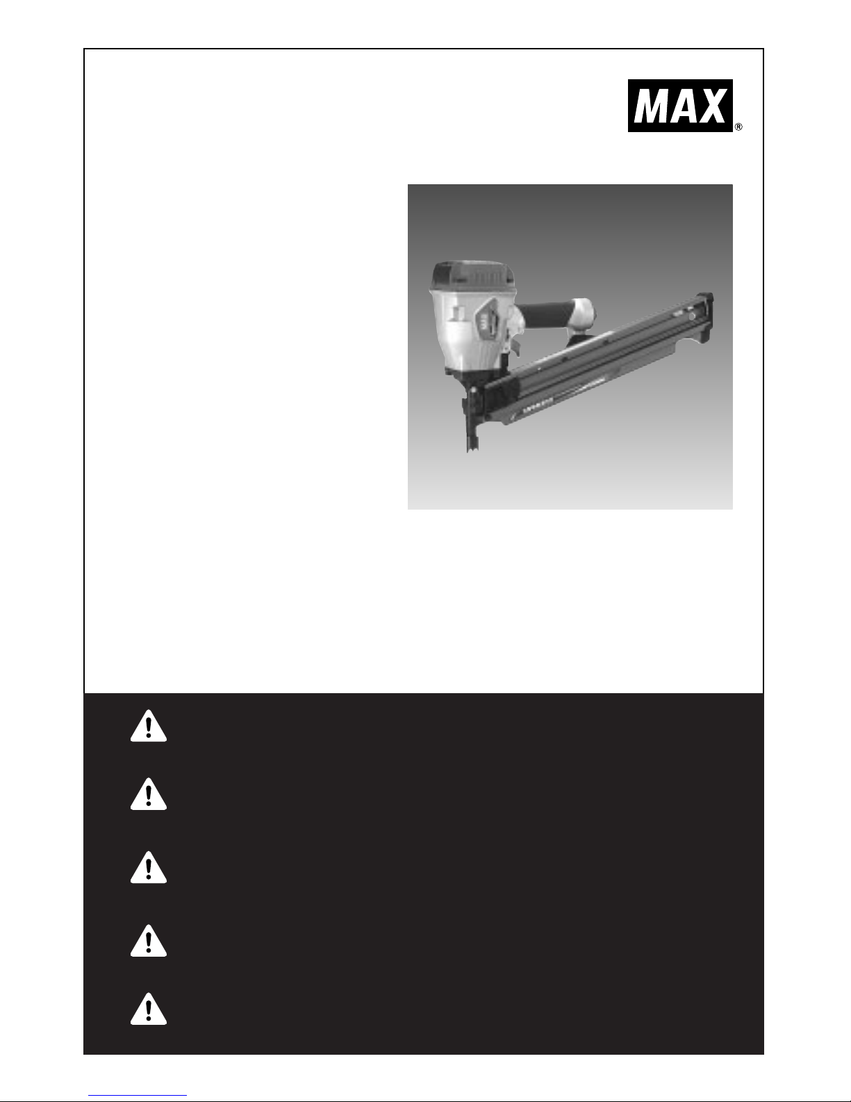
SN883CH/34
(
CE
)
34 DEGREE CLIPPED HEAD FRAMING
STICK NAILER
34-GRAD BEFESTIGTER RAHMENSTOCKHAUPTNAGLER
CLOUEUSE À MANCHE D’ENCADREMENT
DE TÊTE COUPÉE À 34 DEGRÉS
INCHIODATRICE A MANICA DI QUADRO
DI TESTA TAGLIATA A 34 GRADI
CLAVADORA DE BARRA DE MARCO
DE CABEZA CORTADA A 34 GRADOS
OPERATING and MAINTENANCE MANUAL
BETRIEBSANLEITUNG
MANUEL D’UTILISATION et D’ENTRETIEN
MANUALE DI FUNZIONAMENTO E MANUTENZIONE
MANUAL DE OPERACIONES Y MANTENIMIENTO
BEFORE USING THIS TOOL, STUDY THIS MANUAL TO ENSURE SAFETY WARNING AND
INSTRUCTIONS.
KEEP THESE INSTRUCTIONS WITH THE TOOL FOR FUTURE REFERENCE.
WARNING
LESEN SIE VOR INBETRIEBNAHME DES GERÄTES DIE GEBRAUCHS- UND SICHERHEITSHINWEISE. BITTE BEWAHREN SIE DIE GEBRAUCHS- UND SICHERHEITSHINWEISE AUF,
DAMIT SIE AUCH SPÄTER EINGESEHEN WERDEN KÖNNEN.
ACHTUNG
AVANT D’UTILISER CET OUTIL, LIRE CE MANUEL ET LES CONSIGNES DE SECURITE
AFIN DE GARANTIR UN FONCTIONNEMENT SUR.
CONSERVER CE MANUEL EN LIEU SUR AVEC L’OUTIL AFIN DE POUVOIR LE
CONSULTER ULTERIEUREMENT.
AVERTISSEMENT
PRIMA DI USARE QUESTA MACCHINA, STUDIARE IL MANUALE PER PRENDERE ATTO
DEGLI AVVERTIMENTI E DELLE ISTRUZIONIPER LA SICUREZZA.
TENERE QUESTE ISTRUZIONI INSIEME ALLO STRUMENTO PER CONSULTAZIONI FUTURE.
ATTENZIONE
PARA EVITAR GRAVES DAÑOS PERSONALES O EN LA PROPIEDAD.
ANTES DE EMPLEAR LA HERRAMIENTA, LEER CON ATENCIÓN Y COMPRENDER LOS
SIGUIENTES INSTRUCCIONES DE SEGURIDAD.
ATENCIÓN
Page 2

2
DEFINITIONS OF SIGNAL WORDS
WARNING: Indicates a potentially hazardous situation which, if not avoided, could result in death
or serious injury.
CAUTION: Indicates a potentially hazardous situation which, if not avoided, may result in minor or
moderate injury.
NOTE: Emphasizes essential information.
DEFINITIONEN DER HINWEISBEZEICHNUNGEN
ACHTUNG! Zeigt eine eventuell gefährliche Situation an, die den Tod oder schwere Verletzungen
zur Folge haben könnte, wenn sie nicht vermieden wird.
VORSICHT! Zeigt eine eventuell gefährliche Situation an, die leichte oder mittelschwere
Verletzungen zur Folge haben könnte, wenn sie nicht vermieden wird.
HINWEIS: Hebt wichtige Informationen hervor.
DÉFINITIONS DES DIFFÉRENTS DEGRÉS D’ AVERTISSEMENTS
AVERTISSEMENT Indique une situation éventuellement dangereuse qui, si elle n’est pas contournée,
pourrait provoquer la mort ou des blessure sérieuses.
ATTENTION Indique une situation éventuellement dangereuse qui, si elle n’est pas contournée,
pourrait provoquer des blessures légères à moyennement sérieuses.
REMARQUE Souligne des informations importantes.
DEFINIZIONE DELLE INDICAZIONI DI AVVERTIMENTO
ATTENZIONE: Indica l’eventualità che possa verificarsi una situazione pericolosa, la quale se non
viene evitata, può risultare letale o provocare gravi lesioni.
AVVERTENZA: Indica l’eventualità che possa verificarsi una situazione pericolosa, la quale se non
viene evitata, può provocare lesioni di lieve o media entità.
NOTA: Evidenzia informazioni importanti.
DEFINICIÓN DE LAS INDICACIONES DE ADVERTENCIA
¡
ATENCIÓN! Indica una situación potencialmente peligrosa que podría causar la muerte o graves
lesiones si no se evita.
¡
PRECAUCIÓN! Indica una situación potencialmente peligrosa que podría causar lesiones menos
graves o leves si no se evita.
NOTA: Resalta informaciones importantes.
ENGLISH Page 3 to 15 Page
DEUTSCH Page 17 to 29 Page
FRANÇAIS Page 31 to 43 Page
ITALIANO Page 45 to 57 Page
ESPAÑOL Page 59 to 71 Page
INDEX INHALTSVERZEICHNIS INDEX INDICE INDICE
Page 3
3
OPERATING and MAINTENANCE MANUAL
ENGLISH
INDEX
1. SAFETY INSTRUCTIONS
……………………………………………
3
2. SPECIFICATIONS & TECHNICAL DATA
………………………………
7
3. AIR SUPPLY AND CONNECTIONS
……………………………………
8
4. INSTRUCTIONS FOR OPERATION
……………………………………
10
5. MAINTENANCE
………………………………………………………
15
6. STORAGE
………………………………………………………………
15
7. TROUBLESHOOTING/REPAIRS
………………………………………
15
BEFORE USING THIS TOOL, STUDY THIS MANUAL TO ENSURE SAFETY
WARNING AND INSTRUCTIONS.
KEEP THESE INSTRUCTIONS WITH THE TOOL FOR FUTURE REFERENCE.
WARNING
1. SAFETY INSTRUCTIONS
TO AVOID SEVERE PERSONAL INJURY OR
PROPERTY DAMAGE
BEFORE USING THE TOOL, READ
CAREFULLY AND UNDERSTAND THE
FOLLOWING “SAFETY INSTRUCTIONS”.
FAILURE TO FOLLOW WARNINGS COULD
RESULT IN DEATH OR SERIOUS INJURY.
WARNING
1. WEAR SAFETY GLASSES OR GOGGLES
Danger to the eyes always exists due to the
possibility of dust being blown up by the
exhausted air or of a fastener flying up due to
the improper handling of the tool. For these
reasons, safety glasses or goggles shall
always be worn when operating the tool.
The employer and/or user must ensure that
proper eye protection is worn. Eye protection
equipment must conform to the requirements
of Council Directive 89/686/EEC of 21 DEC.
1989 (the American National Standards
Institute, ANSI Z87.1) and provide both frontal
and side protection.
The employer is responsible to enforce the
use of eye protection equipment by the tool
operator and all other personnel in the work
area.
NOTE: Non-side shielded spectacles and
face shields alone do not provide adequate
protection.
PRECAUTIONS ON USING THE TOOL
Page 4
ENGLISH
4
2. EAR PROTECTION MAY BE REQUIRED IN
SOME ENVIRONMENTS
As the working condition may include
exposure to high noise levels which can lead
to hearing damage, the employer and user
should ensure that any necessary hearing
protection is provided and used by the
operator and others in the work area.
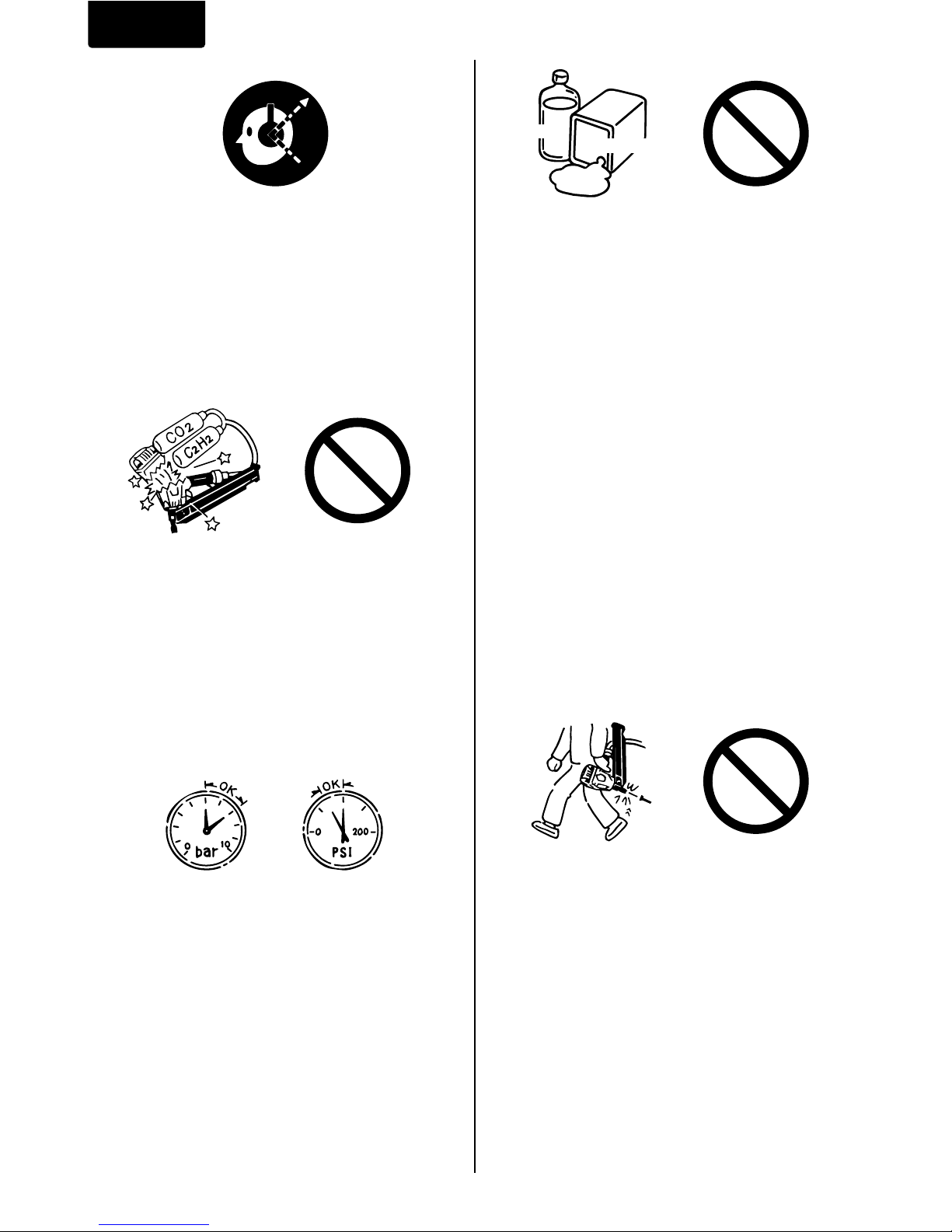
3. DO NOT USE ANY POWER SOURCE
EXCEPT AN AIR COMPRESSOR
The tool is designed to operate on
compressed air. Do not operate the tool on
any other highpressure gas, combustible
gases (e.g., oxygen, acetylene, etc.) since
there is the danger of an explosion. For this
reason, absolutely do not use anything other
than an air compressor to operate the tool.
4. OPERATE WITHIN THE PROPER AIR
PRESSURE RANGE
The tool is designed to operate within an air
pressure range of 5 to 7 bar (70 to 100 p.s.i.).
The pressure should be adjusted to the type
of the work being fastened. The tool shall
never be operated when the operating
pressure exceeds 8 bar (120 p.s.i.).
Never connect the tool to air pressure which
potentially exceeds 14 bar (200 p.s.i.) as the
tool can burst.
5. DO NOT OPERATE THE TOOL NEAR A
FLAMMABLE SUBSTANCE
Never operate the tool near a flammable
substance (e.g., thinner, gasoline, etc.).
Volatile fumes from these substances could
be drawn into the compressor and
compressed together with the air and this
could result in an explosion.
6. NEVER USE THE TOOL IN AN EXPLOSIVE
ATMOSPHERE
Sparks from the tool may ignite atmospheric
gases, dust or other combustible materials.
7. DO NOT USE A WRONG FITTINGS
The connector on the tool must not hold
pressure when air supply is disconnected. If a
wrong fitting is used, the tool can remain
charged with air after disconnecting and thus
will be able to drive a fastener even after the
air line is disconnected, possibly causing
injury.
8. DISCONNECT THE AIR SUPPLY AND
EMPTY THE MAGAZINE WHEN THE TOOL
IS NOT IN USE
Always disconnect the air supply from the tool
and empty the magazine when operation has
been completed or suspended, when
unattended, moving to a different work area,
adjusting, disassembling, or repairing the tool,
and when clearing a jammed fastener.
5
7
70
100
Thinner
Gasoline
Page 5
ENGLISH
5
12. USE SPECIFIED FASTENERS
(SEE PAGE 7)
The use of fasteners other than specified
fasteners will cause the tool malfunction. Be
sure to use only specified fasteners when
operating the tool.
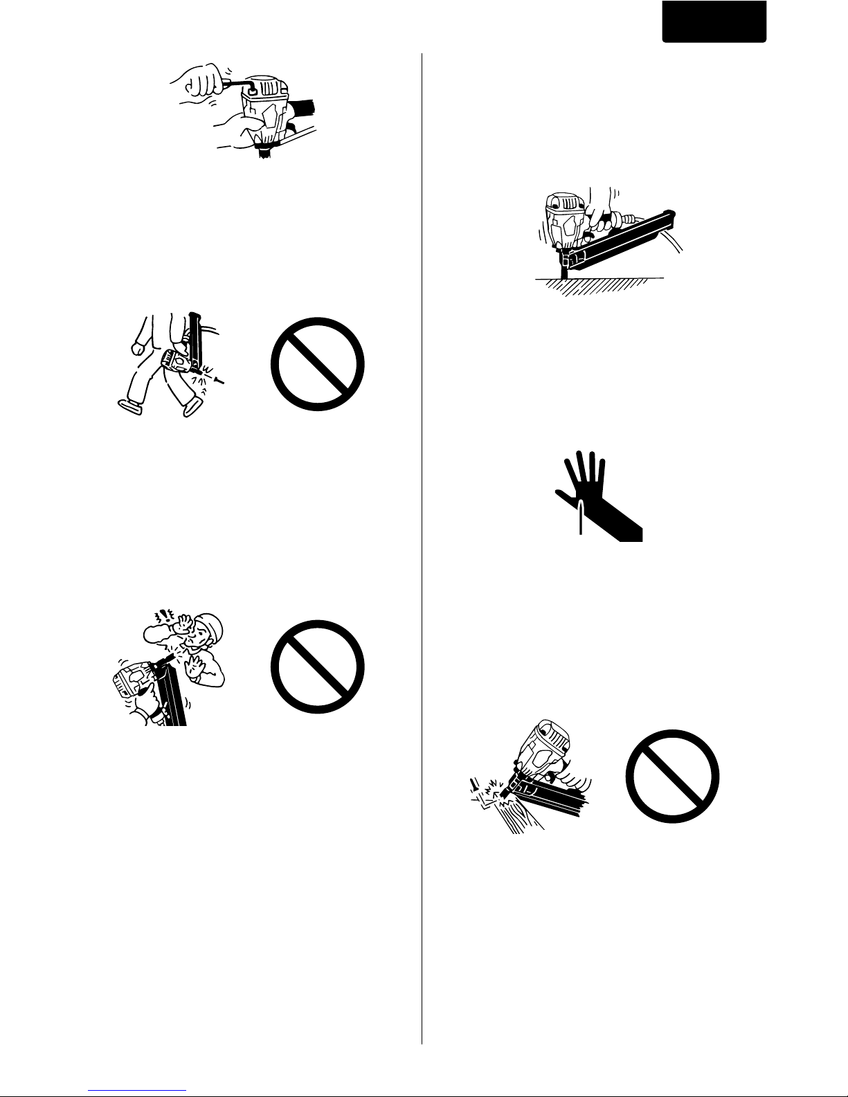
13. PLACE THE DISCHARGE OUTLET ON THE
WORK SURFACE PROPERLY
Failure to place the discharge outlet of the
nose in a proper manner can result in a
fastener flying up and is extremely
dangerous.
14. KEEP HANDS AND BODY AWAY FROM
THE DISCHARGE OUTLET
When loading and using the tool, never place
a hand or any part of body in fastener
discharge area of the tool. It is very
dangerous to hit the hands or body by
mistake.
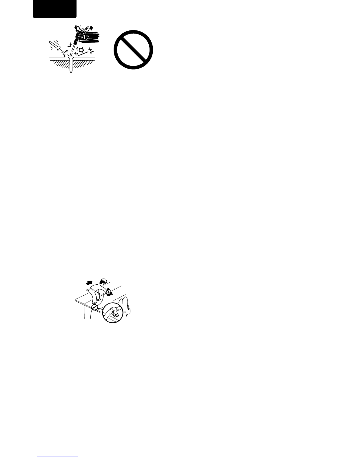
15. DO NOT DRIVE FASTENERS CLOSE TO
THE EDGE AND CORNER OF THE WORK
AND THIN MATERIAL
The workpiece is likely to split and the
fastener could fly free and hit someone.
9. INSPECT SCREW TIGHTNESS
Loose or improperly installed screws or bolts
cause accidents and tool damage when the
tool is put into operation. Inspect to confirm
that all screws and bolts are tight and
properly installed prior to operating the tool.
10. DO NOT TOUCH THE TRIGGER UNLESS
YOU INTEND TO DRIVE A FASTENER
Whenever the air supply is connected to the
tool, never touch the trigger unless you intend
to drive a fastener into the work. It is
dangerous to walk around carrying the tool
with the trigger pulled, and this and similar
actions should be avoided.
11. NEVER POINT THE DISCHARGE OUTLET
TOWARD YOURSELF AND OTHER
PERSONNEL
If the discharge outlet is pointed toward
people, serious accidents may be caused
when misfiring. Be sure the discharge outlet
is not pointed toward people when connecting
and disconnecting the hose, loading and
unloading the fasteners or similar operations.
Page 6
ENGLISH
6
20. NEVER USE THE TOOL IF ANY PORTION
OF THE TOOL CONTROLS (e.g., TRIGGER,
CONTACT ARM) IS INOPERABLE,
DISCONNECTED, ALTERED OR NOT
WOKING PROPERLY
21. NEVER ACTUATE THE TOOL INTO FREE
SPACE
This will avoid any hazard caused by free
flying fasteners and excessive strain of the
tool.
22. ALWAYS ASSUME THAT THE TOOL
CONTAINS FASTENERS
23. RESPECT THE TOOL AS A WORKING
IMPLEMENT
24. NO HORSEPLAY
25. NEVER LOAD THE TOOL WITH
FASTENERS WHEN ANY ONE OF THE
OPERATING CONTROLS (e.g., TRIGGER,
CONTACT ARM) IS ACTIVATED
26. WEAR THE GLOVES DEPENDING ON THE
WORKING CONDITION
27. WHEN DISPOSING THE MACHINE OR ITS
PARTS, FOLLOW THE RELEVANT
NATIONAL RULES
OBSERVE THE FOLLOWING GENERAL
CAUTION IN ADDITION TO THE OTHER
WARNINGS CONTAINED IN THIS
MANUAL
• Do not use the tool as a hammer.
• Always carry the tool by the grip, never
carry the tool by the air hose.
• The tool must be used only for the purpose
it was designed.
• Never remove, tamper with the operating
controls (e.g., TRIGGER, CONTACT ARM)
• Keep the tool in a dry place out of reach of
children when not in use.
• Do not use the tool without Safety Warning
label.
• Do not modify the tool from original design
or function without approval by MAX CO.,
LTD.
16. DO NOT DRIVE FASTENERS ON TOP OF
OTHER FASTENERS
Driving fasteners on the top of other fasteners
may cause deflection fasteners which could
cause injury.
17. REMOVING THE FASTENERS AFTER
COMPLETING OPERATION
If fasteners are left in the magazine after the
completion of operation, there is the danger
of a serious accident occurring prior to the
resumption of operation, should the tool be
handled carelessly, or when connecting the
air fitting. For this reason, always remove all
fasteners remaining in the magazine after
completion of the operation.
18. CHECK OPERATION OF THE CONTACT
TRIP MECHANISM FREQUENTLY IN CASE
OF USING A CONTACT TRIP TYPE TOOL
Do not use the tool if the trip is not working
correctly as accidental driving of a fastener
may result. Do not interfere with the proper
operation of the contact trip mechanism.
19. WHEN USING THE TOOL OUTSIDE OR
ELEVATED PLACE
When fastening roofs or similar slanted
surface, start fastening at the lower part and
gradually work your way up. Fastening
backward is dangerous as you may lose your
foot place.
Secure the hose at a point close to the area
you are going to drive fasteners. Accidents
may be caused due to the hose being pulled
inadvertently or getting caught.
Page 7

ENGLISH
7
1. NAME OF PARTS
2. TOOL SPECIFICATIONS
3. FASTENER SPECIFICATIONS
i
u
w
q
r
e
y
o
t
q
Frame
w
Cylinder Cap
e
Contact Arm
r
Nose
t
Magazine
y
Trigger
u
Grip
i
Exhaust Cover
o
Pusher
!0
Adjustment Dial
2. SPECIFICATIONS AND TECHNICAL DATA
PRODUCT NO. SN883CH/34 (CE)
HEIGHT 310 mm (12-1/4”)
WIDTH 121 mm (4-3/4”)
LENGTH 440 mm (17-3/8”)
WEIGHT 3.2 kg (7.1 lbs.)
RECOMMENDED
5 to 7 bar (70 to 100 p.s.i.)
OPERATING PRESSURE
LOADING CAPACITY 90 Nails
AIR CONSUMPTION
2.18R at 6 bar (90 p.s.i.)
operating pressure
PRODUCT NO. SN883CH/34 (CE)
NAIL LENGTH 50 to 83 mm (2” to 3-1/4”)
SHANK DIAMETER 2.9 to 3.3 mm (.113” to .131”)
SHANK TYPE Smooth, Ring, Screw
HEAD DIAMETER 6.5 to 7.7 mm (.256” to .303”)
COLLATION ANGLE 34 degree
HEAD Clipped head
!0
*The machine has been designed
compact so that you can use it in
the narrow space.
Page 8

ENGLISH
8
TOOL AIR FITTINGS:
This tool uses a 3/8” N.P.T. male plug. The inside
diameter should be 9.9mm (.39”) or larger. The
fitting must be capable of discharging tool air
pressure when disconnected from the air supply.
RECOMMENDED OPERATING
PRESSURE:
5 to 7 bar (70 to 100 p.s.i.). Select the operating
air pressure within this range for best fastener
performance.
DO NOT EXCEED 8 bar (120 p.s.i.).
5. APPLICATIONS
*Floor and wall framing
*Subflooring
*Roof and wall sheathing
*Fencing
4. TECHNICAL DATA
q NOISE
A-weighted single-event sound power level
------ LWA, 1s, d 94.6 dB
A-weighted single-event emission sound
pressure level at work station
------- LpA, 1s, d 90.28 dB
These values are determined and documented
in accordance to EN12549 : 1999.
w VIBRATION
Vibration characteristic value = 4.1 m/s
2
These values are determined and documented
in accordance to ISO 8662-11.
This value is a tool-related characteristic value
and does not represent the influence to the
hand-arm-system when using the tool. An
influence to the hand-arm-system when using
the tool will, for example, depend on the
gripping force, the contact
pressure force, the working
direction, the adjustment of
mains supply, the
workpiece, the workpiece
support.
3. AIR SUPPLY AND
CONNECTIONS
Read section titled “SAFETY
INSTRUCTIONS”.
DO NOT USE ANY POWER SOURCE EXCEPT
AN AIR COMPRESSOR
The tool is designed to operate on compressed
air. Do not operate the tool on any other
highpressure gas, combustible gases (e.g.,
oxygen, acetylene, etc.) since there is the danger
of an explosion. For this reason, absolutely do not
use anything other than an air compressor to
operate the tool.
OPERATE WITHIN THE PROPER AIR
PRESSURE RANGE
The tool designed to operate within an air
pressure range of 5 to 7 bar (70 to 100 p.s.i.).
The pressure should be adjusted to the type of
the work being fastened. The tool shall never be
operated when the operating pressure exceeds 8
bar (120 p.s.i.).
WARNING
5
7
70
100
Page 9

ENGLISH
9
DO NOT OPERATE THE TOOL NEAR A
FLAMMABLE SUBSTANCE
Never operate the tool near a flammable
substance (e.g., thinner, gasoline, etc.). Volatile
fumes from these substances could be drawn into
the compressor and compressed together with
the air and this could result in an explosion.
DO NOT USE A WRONG FITTINGS
The connector on the tool must not hold pressure
when air supply is disconnected. If a wrong fitting
is used, the tool can remain charged with air after
disconnecting and thus will be able to drive a
fastener even after the air line is disconnected,
possibly causing injury.
DISCONNECT THE AIR SUPPLY AND EMPTY
THE MAGAZINE WHEN THE TOOL IS NOT IN
USE
Always disconnect the air supply from the tool
and empty the magazine when operation has
been completed or suspended, when unattended,
moving to a different work area, adjusting,
disassembling, or repairing the tool, and when
clearing a jammed fastener.
FITTINGS: Install a male plug on the tool which is
free flowing and which will release air pressure
from the tool when disconnected from the supply
source.
HOSES: Hose has a min. ID of 6 mm (1/4”) and
max. length of no more than 5 meters (17”).
The supply hose should contain a fitting that will
provide “quick disconnecting” from the male plug
on the tool.
SUPPLY SOURCE: Use only clean regulated
compressed air as a power source for the tool.
3-PIECE AIRSET (Air filter, Regulator, Oiler):
Refer to TOOL SPECIFICATIONS for setting the
correct operating pressure for the tool.
NOTE:
A filter will help to get the best performance and
minimum wear from the tool because dirt and
water in the air supply are major causes of wear
in the tool.
Frequent, but not excessive, lubrication is
required for the best performance. Oil added thru
the air line connection will lubricate the internal
parts.
Air compressor
[
AIR SUPPLY & CONNECTIONS
]
Air filter
Air hose
Oiler
Used at 5 to 7 bar (70 to 100 p.s.i.)
Regulator
[
AIR SUPPLY & CONNECTIONS
]
3-piece airset
100
70
5
7
Thinner
Gasoline
Page 10

ENGLISH
10
4. INSTRUCTIONS FOR
OPERATION
2. OPERATION
Wear safety glasses or goggles. Danger to the
eyes always exists due to the possibility of dust
being blown up by the exhausted air or of a
fastener flying up due to the improper handling of
the tool. For these reasons, safety glasses or
goggles shall always be worn when operating the
tool.
The employer and/or user must ensure that
proper eye protection is worn. Eye protection
equipment must conform to the requirements of
Council Directive 89/686/EEC of 21 DEC. 1989
(the American National Standards Institute, ANSI
Z87.1) and provide both frontal and side
protection.
The employer is responsible to enforce the use of
eye protection equipment by the tool operator and
all other personnel in the work area.
NOTE: Non-side shielded spectacles and face
shields alone do not provide adequate protection.
WARNING
WARNING
Keep hands and body away from the discharge
outlet when driving the fasteners because of
dangerous of hitting the hands or body by
mistake.
Nails
Read section titled “SAFETY
INSTRUCTIONS”.
1. BEFORE OPERATION
Check the following prior operation.
q
Wear Safety Glasses or Goggles.
w
Do not connect the air supply.
e
Inspect screw tightness.
r
Check operation of the contact arm & trigger if
moving smoothly.
t
Connect the air supply.
y
Check the air-leakage. (The Tool must not
have the air-leakage.)
u
Hold the Tool with finger-off the trigger, then
push the contact arm against the work-piece.
(The tool must not operate.)
i
Hold the Tool with contact arm free from workpiece and pull the trigger. (The Tool must not
operate.)
o
Disconnect the air supply.
NAIL LOADING
●
When loading the nails, be sure to release
the finger from the Trigger.
●
Do not press the Contact Arm against the
object.
PROCEDURE
q
Load the nails into the slot in the rear of the
Magazine until they go over the Nail Stopper.
WARNING
Nail Stopper
Page 11

ENGLISH
11
TEST OPERATION
q
Adjust the air pressure at 5 bar (70 p.s.i.) and
connect the air supply.
w
Without touching the trigger, depress the
contact arm against the work-piece.
Pull the trigger. (The tool must fire the
fastener.)
e
With the tool off the work-piece, pull the
trigger.
Then depress the contact arm against the
work-piece. (The tool must fire the fastener.)
r
Adjust the air pressure as much as the lowest
possible according the length of fastener and
the hardness of work-piece.
MODEL IDENTIFICATION
CONTACT TRIP MODEL with ANTI-DOUBLE
FIRE MECHANISM
The anti-double fire mechanism (US patent
5597106, UK patent 2286790) is installed on this
tool.
The common operating procedure on “Contact
Trip” tools is for the operator to contact the work
to actuate the trip mechanism while keeping the
trigger pulled, thus driving a fastener each time
the work is contacted. This will allow rapid
fastener placement on many jobs, such as
sheathing, decking and pallet assembly. All
pneumatic tools are subject to recoil when driving
fasteners. The tool may bounce, releasing the
trip, and if unintentionally allowed to re-contact
the work surface with the trigger still actuated
(finger still holding trigger pulled) an unwanted
second fastener will be driven.
CONTACT TRIP WITH ANTI-DOUBLE FIRE
MECHANISM
(US patent 5597106, UK patent 2286790)
Identified by BLACK TRIGGER.
w
Pull the Pusher as far as the rear end of the
magazine and release it gently.
Pusher
Abrupt release of the Pusher causes jamming
of nails or dry-firing.
CAUTION
Page 12

ENGLISH
12
2
1
DRIVING FASTENERS
CONTACT FIRE OPERATION
For contact fire operation, hold the Trigger and
depress the Contact Arm against the work
surface.
PROCEDURE
q
Hold the Trigger.
w
Depress the Contact Arm.
1
2
SINGLE FIRE OPERATION
(ANTI-DOUBLE FIRE MECHANISM)
For single fire operation, depress the Contact Arm
against the work surface and pull the Trigger.
Tool cannot fire a second nail until the Trigger is
released and tool can cycle.
PROCEDURE
q
Depress the Contact Arm.
w
Pull the Trigger.
SEQUENTIAL TRIP
The Sequential Trip requires the operator to hold
the tool against the work before pulling the trigger.
This makes accurate fastener placement easier,
for instance on framing, toe nailing and crating
applications. The Sequential Trip allows exact
fastener location without the possibility of driving
a second fastener on recoil, as described under
“Contact Trip”.
The Sequential Trip Tool has a positive safety
advantage because it will not accidentally drive a
fastener if the tool is contacted against the workor anything else-while the operator is holding the
trigger pulled.
SEQUENTIAL TRIP
Identified by ORANGE TRIGGER.
When using the tool with both hands;
Hold the rear of the magazine to use.
Do not hold the front of the magazine because
your hand may be injured by nails.
WARNING
Page 13

ENGLISH
13
Adjustment Dial
ALWAYS disconnect air supply before dial
adjustment.
q
With air pressure set, drive nails into a
representative material sample to determine if
adjustment is necessary.
w
If adjustment is required, disconnect air
supply.
e
Refer to the mark on the Adjust Spacer for
direction to turn the adjustment dial.
r
Reconnect air supply.
WARNING
Trigger lock dial
Trigger
(LOCK)
(UNLOCK)
TRIGGER LOCK MECHANISM
The tool is equipped with a trigger lock
mechanism. Push and rotate the trigger LOCK to
the trigger UNLOCK position before driving nails.
Deeper Shallow
Contact Tip
Contact Arm
ALWAYS disconnect air supply before
attaching / detaching the contact tip.
Attach the Contact Tip on the tip of Contact Arm,
when driving nails to a soft material.
WARNING
The Contact Tip can be kept on the Contact Tip
holder when not using.
Contact Tip
Contact Tip holder
ADJUSTABLE DIAL DEPTH CONTROL
TRIGGER LOCK MECHANISM
CONTACT TIP (OPTION)
Page 14

ENGLISH
14
ALWAYS disconnect air supply before
removing jammed nails.
REMOVING JAMMED NAILS
WARNING
PROCEDURE
q
Push the Pusher Lever and release the strip
nails from the Pusher.
Pusher Lever
w
Push the Nail Stopper, and remove the strip
nails from inside of the Magazine.
Nail Stopper
e
Pull and stayed the Pusher back using the
hole and a rod.
r
Remove the jammed nail from the Nose using
a punch or a slotted screw driver.
PusherHole
Rod
Page 15

ENGLISH
15
5. MAINTENANCE
w
DO NOT FIRE THE STAPLER WHEN IT IS
EMPTY
e
USE A 3-PIECE AIRSET
Failure to use a 3-piece airset allows the
moisture and dirt inside compressor to pass
into the tool directly. This causes rust and
wear, and results in a poor operating
performance. The hose length between airset
and tool should be no longer than 5 m since a
longer length results in a reduction in air
pressure.
r
USE RECOMMENDED OIL
The velocite or turbine oil should be used to
lubricate the tool. Upon completion of
operations, place 2 or 3 drops of oil into the air
plug inlet with the jet oiler. (Recommended Oil
: ISO VG32)
t
INSPECT AND MAINTAIN DAILY OR
BEFORE OPERATION
Disconnect air supply and empty the
magazine when inspecting or maintaining the
tool.
(1) Drain air line filter and compressor
(2) Keep lubricator filled in air 3-pieces set
(3) Clean filter element of air 3-pieces set
(4) Tighten all screws
(5) Keep contact arm moving smoothly
6. STORAGE
q
When not in use for an extended period, apply
a thin coat of the lubricant to the steel parts to
avoid rust.
w
Do not store the tool in a cold weather
environment. Keep the tool in a warm area.
e
When not in use, the tool should be stored in a
warm and dry place. Keep out of reach of
children.
r
All quality tools will eventually require servicing
or replacement of parts because of wear from
the normal use.
7. TROUBLE
SHOOTING/REPAIRS
The troubleshooting and/or repairs shall be
carried out only by the MAX CO., LTD. authorised
distributors or by other specialists.
WARNING
Supplement to the operating instruction
According to the European Norm EN 792-13 the
regulation is valid from 01.01.2001 that all
fastener driving tools with contact actuation must
be marked with the symbol “Do not use on
scaffoldings, ladders” and they shall not be used
for specific application for example:
*when changing one driving location to another
involves the use of scaffoldings, stairs, ladders
or ladder alike constructions e.g. roof laths,
*closing boxes or crates,
*fitting transportation safety systems e.g. on
vehicles and wagons.
q
ABOUT PRODUCTION YEAR
This product bears production number at the
lower part of the grip of the main body. The
two digits of the number from left indicates the
production year.
(Example)
0 8 8 2 6 0 3 5 D
Year 2008
Page 16

73
3
1
2
4
5
112
7
8
9
10
9
11
12
13
14
15
16
17
18
19
20
22
28
29
30
31
201
32
33
34
35
36
87
37
38
39
40
41
42
44
47
49
51
48
46
45
50
23
25
24
26
65
63
79
85
76
77
6
84
55
58
59
80
52
54
57
58
55
60
61
64
205
75
78
53
202
62
72
27
73
68
66
67
70
72
69
71
83
203
89
82
81
O-RING KIT
Parts marked
in included
are
the O-ring kit
27
55
27
86
27
90
70
56
43
70
204
28
29
30
31
32
33
101
35
102
103
38
39
104
105
47
108
109
111
43
50
110
106
107
21
207
206
74
113
70
115
208
EXPLODED
VIEW AND SPARE
PARTS LIST
EINZELTEILDAR-
STELLUNG UND
ERSATZEILLISTE
SCHEMA ECLATE ET
LISTE DES PIECES
DE RECHANGE
ESPLOSO DEI
COMPONENTI DE
ELENCO DELLE
PARTI DI RICAMBIO
DESPIECE DE LA
MAQUINA Y LISTA
DE RECAMBIOS
SN883CH/34
PNEUMATIC STAPLER
Page 17

74
SN883CH/34
ESPAÑOLITALIANOFRANÇAISENGLISHMATERIAL DEUTSCH
ITEM
NO.
PART
NO.
1
2
3
4
5
6
7
8
9
10
11
12
13
14
15
16
17
18
19
20
21
22
23
24
25
26
27
28
29
30
31
32
33
34
35
36
37
38
39
40
41
42
43
44
45
46
47
48
49
50
51
52
53
54
55
56
57
58
59
BB40406
KN12187
KN12194
BB40429
KN70093
KK23976
KN12186
KN12185
HH14150
HH11161
KN70097
HH19218
KN70111
KN12189
KN12190
HH12121
HH12107
KN12188
CN35325
KN12193
KN81019
KN12205
KN12206
BB40460
CN35685
KN11247
EE31121
HH11125
HH11138
CN33909
FF30161
HH11119
HH11209
CN31589
HH11113
KK24161
KN12214
HH11901
CN33910
HS10144
KN12274
HS10147
FF22402
HS10145
HS10146
CN34500
KK23129
KK23943
KN12207
TA15144
KN12212
HH14729
KN12200
KN12223
BB40415
HH12111
BB40443
EE39172
KN12224
SCREW 5X12 SCHRAUBE 5X12 VIS 5X12 VITE 5X12 TORNILLO 5X12
EXHAUST FILTER AUSLASSFILTER FILTRE ECHAPPEMENT FILTRO DI SCARICA FILTRO DE ESCAPE
EXHAUST COVER ABSAUGHAUBE CAPOT D'ASPIRATION
COPERCHIO DELLO SCARIO CAMPANA DE ASPIRACIÓN
SCREW 6X28 SCHRAUBE 6X28 VIS 6X28 VITE 6X28 TORNILLO 6X28
CYLINDER CAP UNIT
ZYLINDERDECKEL KOMPL.
GRUPPO COPERCHIO CILINDRO CUBIERTA DE CILINDRO COMPL.
COMPRESSION SPRING 3976
DRUCKFEDER 3976
RESSORT À PRESSION 3976
MOLLA DI COMPRESSIONE 3976 MUELLE DE COMPRESIÓN 3976
PISTON STOP KOLBENANSCHLAG BUTÉE DE PISTON FERMO STANTUFFO TOPE EMBOLO
HEAD VALVE PISTON KOPFVENTILKOLBEN
PISTON DE CLAPET DE TÉTE
STANTUFFO VALVOLA DI MANDATA
EMBOLO VÁLVULA DEL CABEZAL
O-RING AS568-150 O-RING AS568-150
JOINT TORIQUE AS568-150
O-RING AS568-150
ANILLO TÓRICO AS568-150
O-RING AS568-142 O-RING AS568-142
JOINT TORIQUE AS568-142
O-RING AS568-142
ANILLO TÓRICO AS568-142
CYLINDER CAP SEAL UNIT
ZYLINDERABDECKSCHEIBE-KOMPL.
O-RING 4.5X48.8 O-RING 4.5X48.8
JOINT TORIQUE 4.5X48.8
O-RING 4.5X48.8
ANILLO TÓRICO 4.5X48.8
MAIN PISTON UNIT
ARBEITSKOLBEN KOMPL.
PISTON DE TRAVAIL COMPLET
GRUPPO STANTUFFO OPERATORE
EMBOLO DE TRAVAJO COMPL.
CYLINDER SEAL
ZYLINDERABDECKSCHEIBE
RONDELLE DE CYLINDRE
RONDELLA DI CILINDRO ARANDELA DE CILINDRO
CYLINDER RING ZYLINDERRING JOINT DE CYLINDRE ANELLO DI CILINDRO ANILLO DE CILINDRO
O-RING 1AG100 O-RING 1AG100 JOINT TORIQUE 1AG100 O-RING 1AG100 ANILLO TÓRICO 1AG100
O-RING 1AG70 O-RING 1AG70 JOINT TORIQUE 1AG70 O-RING 1AG70 ANILLO TÓRICO 1AG70
CYLINDER ZILINDER CYLINDRE CILINDRO CILINDRO
CHECK PAWL SPERRKLINKE CLIQUET D'ARRÊT NOTTOLINO DI ARRESTO TRINQUETE
BUMPER STOSSDÄMPFER AMORTISSEUR AMMORTIZZATORE AMORTIGUADOR
FRAME GEHÄUSE BOÎTIER ALLOGGIAMENTO CARCASA
NAME LABEL A NAMENSSCHILD A JOINT DE NOM A SIGILLO DI NOME A JUNTA DE NOMBRE A
NAME LABEL B NAMENSSCHILD B JOINT DE NOM B SIGILLO DI NOME B JUNTA DE NOMBRE B
SCREW 5X28 SCHRAUBE 5X28 VIS 5X28 VITE 5X28 TORNILLO 5X28
END CAP FILTER SA-10
ABSCHLUSSKAPPEFILTER SA-10
END CAP ABSCHLUSSKAPPE
CAPOT DE RECOUVREMENT
CAPPUCCIO DI CHIUSURA
CAPERUZA DE CIERRE
PLANE WASHER 1-5
GLATTE UNTERLEGSCHEIBE 1-5
RONDELLE LISSE 1-5 RONDELLA PIANA 1-5 ARANDELA LISA 1-5
O-RING 1AP12 O-RING 1AP12 JOINT TORIQUE 1AP12 O-RING 1AP12 ANILLO TÓRICO 1AP12
O-RING 1AP20 O-RING 1AP20 JOINT TORIQUE 1AP20 O-RING 1AP20 ANILLO TÓRICO 1AP20
TRIGGER VALVE HOUSING
BETÄTIGUNGSVENTILGEHÄUSE
PARALLEL PIN 161 PARALLELBOLZEN 161
GOUPILLE PARALLELE 161
PERNO PARALLELO 161 PERNO PARALELO 161
O-RING 1AP6 O-RING 1AP6 JOINT TORIQUE 1AP6 O-RING 1AP6 ANILLO TÓRICO 1AP6
O-RING 1BP7 O-RING 1BP7 JOINT TORIQUE 1BP7 O-RING 1BP7 ANILLO TÓRICO 1BP7
PILOT VALVE STEUERVENTIL VANNE-PILOTE VALVOLA DI COMANDO VÁLVULA DE CONTROL
O-RING 1AP9 O-RING 1AP9 JOINT TORIQUE 1AP9 O-RING 1AP9 ANILLO TÓRICO 1AP9
COMPRESSION SPRING 4161
DRUCKFEDER 4161
RESSORT À PRESSION 4161
MOLLA DI COMPRESSIONE 4161 MUELLE DE COMPRESIÓN 4161
TRIGGER VALVE STEM
BETÄTIGUNGSVENTILSCHAFT
TIGE DE SOUPAPE DE COMMANDE STELO VALVOLA DI AZIONAMENTO
O-RING 1B 1.4X2.5 O-RING 1B 1.4X2.5
JOINT TORIQUE 1B 1.4X2.5
O-RING 1B 1.4X2.5
ANILLO TÓRICO 1B 1.4X2.5
TRIGGER VALVE CAP
BETÄTIGUNGSVENTILDECKEL
CONTCT LEVER B KONTAKTHEBEL B LEVIER DE CONTACT B LEVA DI CONTATTO B
PALANCA DE CONTACTO B
CONTCT LEVER A KONTAKTHEBEL A LEVIER DE CONTACT A LEVA DI CONTATTO A
PALANCA DE CONTACTO A
TRIGGER BETÄTIGUNGSHEBEL LEVIER DE COMMANDE GRILLETTO
PALANCA DE ACCIONAMIENTO
ROLL PIN 3X16 ROLLENBOLZEN 3X16
TOURILLON DE CYLINDRE 3X16
PERNO DI ROTOLAMENT 3X16
PERNO DE RODILLO 3X16
SWITCH LEVER A FAHRSCHALTHEBEL A
LEVIER D'INTERRUPTEUR A LEVA DELL'INTERRUTTORE A
PALANCA DEL INTERRUPTOR A
SWITCH LEVER B FAHRSCHALTHEBEL B
LEVIER D'INTERRUPTEUR B LEVA DELL'INTERRUTTORE B
PALANCA DEL INTERRUPTOR B
SWITCH SPRING SCHALTERFEDER
RESSORT D'INTERRUPTEUR MOLLA DELL'INTERRUTTORE MUELLE DEL INTERRUPTOR
COMPRESSION SPRING 3129
DRUCKFEDER 3129
RESSORT À PRESSION 3129
MOLLA DI COMPRESSIONE 3129 MUELLE DE COMPRESIÓN 3129
COMPRESSION SPRING 3943
DRUCKFEDER 3943
RESSORT À PRESSION 3943
MOLLA DI COMPRESSIONE 3943 MUELLE DE COMPRESIÓN 3943
ARM GUIDE ARMFÜHRER
GUIDE DE BRAS DE CONTACT
GUIDA DEL BRACCIO DI CONTATTO
GUÍA DEL BRAZO
EXHAUST SEAL AUSLASSSCHEIBE
RONDELLE ECHAPPEMENT
RONDELLA DI SCARICA ARANDELA DE ESCAPE
CONTACT ARM A KONTAKTARM A BARRE DE CONTACT A
BRACCIO DI CONTATTO A
BRAZO DE CONTACTO A
O-RING AS568-144 O-RING AS568-144
JOINT TORIQUE AS568-144
O-RING AS568-144
ANILLO TÓRICO AS568-144
ADJUST DIAL
EINSTELLVORWAHLKNOPF
CADRAN DE RÉGLAGE
MANOPOLA DI REGOLAZIONE
CUADRANTE DE AJUSTE
NOSE NAGLERNASE NEZ DE CLOUEUR PUNTA SPARACHIODI NARIZ
SCREW 5X10 SCHRAUBE 5X10 VIS 5X10 VITE 5X10 TORNILLO 5X10
O-RING 1AG45 O-RING 1AG45 JOINT TORIQUE 1AG45 O-RING 1AG45 ANILLO TÓRICO 1AG45
SCREW 8X28 SCHRAUBE 8X28 VIS 8X28 VITE 8X28 TORNILLO 8X28
PLANE WASHER 5.1X12X1.2 RONDELLE LISSE 5.1X12X1.2
RONDELLA PIANA 5.1X12X1.2
ARANDELA LISA 5.1X12X1.2
MAGAZINE GUIDE B MAGAZINFÜHRER B GUIDE DE MAGASIN B GUIDA CARICATORE B GUÎA DE CARGADOR B
COUVERCLE DE CYLINDRE
COMPLET
UNITE DE RONDELLE DE
COUVERCLE DE CYLINDRE
GRUPPO COPERCHIO DI
RONDELLA DI CILINDRO
COMPL. DE CUBIERTA DE
ARANDELA DE CILINDRO
FILTRE SA-10 DE CAPOT DE
RECOUVREMENT
FILTRO DE CAPERUZA DE
CIERRE SA-10
FILTRO DEL CAPPUCCIO DI
CHIUSURA SA-10
CARTER DE SOUPAPE DE
DÉCLENCHEMENT
ALLOGGIO DELLA VALVOLA DI
INNESCO
CUBIERTA DE VÁLVULA DEL
DISPARADOR
VÁSTAGO VÁLVULA DE
ACCIONAMIENTO
CAPUCHON DE SOUPAPE DE
COMMANDE
GLATTE UNTERLEGSCHEIBE
5.1X12X1.2
COPERCHIO VALVOLA DI
AZIONAMENTO
CAPERUZA VÁLVULA DE
ACCIONAMIENTO
Steel
Stainless steel
Steel
Steel
Aluminum
Stainless steel
Urethane
Aluminum
Rubber
Rubber
Stainless steel, Rubber
Rubber
Magnesium, Steel
Urethane
Polyacetal
Rubber
Rubber
Aluminum
Rubber
Rubber
Aluminum
Aluminum
Aluminum
Steel
Nylon
Aluminum
Steel
Rubber
Rubber
Polyacetal
Stainless steel
Rubber
Rubber
Polyacetal
Rubber
Stainless steel
Steel
Rubber
Polyacetal
Steel
Steel
Polyacetal
Stainless steel
Nylon
Steel
Stainless steel
Stainless steel
Stainless steel
Nylon
Rubber
Steel
Rubber
Polyacetal
Steel
Steel
Rubber
Steel
Steel
Rubber
Page 18

75
SN883CH/34
ESPAÑOLITALIANOFRANÇAISENGLISHMATERIAL DEUTSCH
ITEM
NO.
PART
NO.
60
61
62
63
64
65
66
67
68
69
70
71
72
73
74
75
76
77
78
79
80
81
82
83
84
85
86
87
89
90
101
102
103
104
105
106
107
108
109
110
111
112
113
115
201
202
203
204
205
206
207
208
KN12216
KK23964
KN12222
HH19722
KN70120
JJ10102
KN12210
KN12227
KN12226
KN12228
CC49411
KN12229
BB40408
KN12182
KN81022
EE39609
KK44021
FF31572
KN12232
KN12230
FF31603
CN35075
KK23507
CN35074
GN10424
KN12231
CN31083
KK24162
FF21235
KN12213
CN32246
KK24123
CN35128
HN10100
HS10118
HN10786
KN12277
KN12278
KN12276
KK33300
KK23973
KK23944
KN12405
BB40027
KN81017
KN81018
KN81016
KN81027
KN11237
KN12547
KN12546
KN81035
Rubber
Stainless steel
Steel
Rubber
Steel
Stainless steel
Polyacetal
Stainless steel
Stainless steel
Steel
Steel, Nylon
Nylon
Steel
Stainless steel
Aluminum
Steel
Stainless steel
Stainless steel
Nylon
Steel
Steel
Nylon
Stainless steel
Nylon
Polyacetal
Nylon
Rubber
Stainless steel
Steel
Stainless steel
Polyacetal
Stainless steel
Steel
Steel
Polyacetal
Stainless steel
Steel
Nylon
Steel
Stainless steel
Stainless steel
Stainless steel
Steel, Stainless steel
Steel
Urethane
Polyethylene terephthalate
Polyethylene terephthalate
MAGAZINE GUIDE A MAGAZINFÜHRER A GUIDE DE MAGASIN A GUIDA CARICATORE A GUÍA DE CARGADOR A
COMPRESSION SPRING 3964
DRUCKFEDER 3964
RESSORT Á PRESSION 3964
MOLLA DI COMPRESSIONE 3964 MUELLE DE COMPRESIÓN 3964
CONTACT BOLT
KONTAKTSCHRAUBBOLZEN
BOULON DE CONTACT BULLONE DI CONTATTO PERNO DE CONTACTO
O-RING 1A 1.5x5 O-RING 1A 1x6.2 JOINT TORIQUE 1A 1x6.2 O-RING 1A 1x6.2
ANILLO TÓRICO 1A 1x6.2
CONTACT ARM B UNIT KONTAKTARM B BARRE DE CONTACT B
BRACCIO DI CONTATTO B
BRAZO DE CONTACTO B
E-RETAINING RING 5 E-HALTERING 5 BAGUE DE RETENUE E 5 ANELLO DI RITEGNO E 5
ANILLO DE RETENCIÓN EN E 5
NAIL GUIDE B NAGELFÜHRER B GUIDE DE CLOUS B GUIDA DI CHIODI B GUÍA DE CLAVOS B
NAIL GUIDE A NAGELFÜHRER A GUIDE DE CLOUS A GUIDA DI CHIODI A GUÍA DE CLAVOS A
NAIL COVER NAGELDECKEL COUVERCLE DE CLOUS COPERCHIO DI CHIODI CUBIERTA DE CLAVOS
TAIL HANGER SCHWANZHALTER SUPPORT DE QUEUE SUPPORTO DI CODA SOPORTE DE COLA
NUT M5 MUTTER M5 ECROU M5 DADO M5 TUERCA M5
TAIL COVER SCHWANZDECKEL COUVERCLE DE QUEUE COPERCHIO DI CODA CUBIERTA DE COLA
SCREW 5X14 SCHRAUBE 5X14 VIS 5X14 VITE 5X14 TORNILLO 5X14
NAIL STOPPER NAGELSTOPPER PIECE ARRET DE CLOUS FERMO DI CHIODI TOPE DE CLAVOS
MAGAZINE MAGAZIN MAGASIN CARICATORE CARGADOR
RUBBER WASHER 1.8x6x2
GUMMISCHEIBE 1.8x6x2
DISQUE DE CAOUTCHOUC 1.8x6x2
ROUNDELLA IN GOMMA1.8x6x2 ARANDELA DE CAUCHO 1.8x6x2
SPIRAL SPRING 4021 SPIRALFEDER 4021 RESSORT SPIRAL 4021 MOLLA SPIRALE 4021 MUELLE ESPIRAL 4021
PARALLEL PIN 1572 PARALLELBOLZEN 1572
GOUPILLE PARALLELE 1572
PERNO PARALLELO 1572
PERNO PARALELO 1572
PUSHER HOLDER SCHIEBERHALTER SUPPORT DE POUSSOIR SUPPORTO SPINGITOIO
SOPORTE DE EMPUJADOR
PUSHER SCHIEBER POUSSOIR SPINGITOIO EMPUJADOR
PARALLEL PIN 1603 PARALLELBOLZEN 1603
GOUPILLE PARALLELE 1603
PERNO PARALLELO 1603
PERNO PARALELO 1603
TRIGGER LOCK LEVER
BETÄTIGUNGSSPERREHEBEL LEVA DI SICURA GRILLETTO
COMPRESSION SPRING 3507
DRUCKFEDER 3507
RESSORT Á PRESSION 3507
MOLLA DI COMPRESSIONE 3507 MUELLE DE COMPRESIÓN 3507
TRIGGER LOCK DIAL
BETÄTIGUNGSSPERREKNOPF
DISCO DI SICURA GRILLETTO
SPRING COLLAR FEDERSSTELLRING COLLIER DE RESSORT COLLARE DELLA MOLLA COLLAR DE MUELLE
ARM COVER ARMABDECKUNG COUVERCLE DE BRAS
COPERCHIO DEL BRACCIO
CUBIERTA DEL BRAZO
DUST COVER HOOK STAUBDECKELHAKEN
COMPRESSION SPRING 4162
DRUCKFEDER 4162
RESSORT Á PRESSION 4162
MOLLA DI COMPRESSIONE 4162 MUELLE DE COMPRESIÓN 4162
ROLL PIN 3X30 ROLLENBOLZEN 3X30
TOURILLON DE CYLINDRE 3X30
PERNO DI ROTOLAMENT 3X30
PERNO DE RODILLO 3X30
SWITCHING LEVER SCHAKELHEFBOOM
LEVIER DE COMMUTATION
LEVA DI COMMUTAZIONE
PALANCA DE CONMUTACIÓN
PILOT VALVE STEUERVENTIL VANNE-PILOTE VALVOLA DI COMANDO VÁLVULA DE CONTROL
COMPRESSION SPRING 4123
DRUCKFEDER 4123
RESSORT À PRESSION 4123
MOLLA DI COMPRESSIONE 4123 MUELLE DE COMPRESIÓN 4123
TRIGGER VALVE STEM
BETÄTIGUNGSVENTILSCHAFT
TIGE DE SOUPAPE DE COMMANDE STELO VALVOLA DI AZIONAMENTO
CONTACT LEVER KONTAKTHEBEL LEVIER DE CONTACT LEVA DI CONTATTO PALANCA DE CONTACTO
TRIGGER BETÄTIGUNGSHEBEL LEVIER DE COMMANDE GRILLETTO
PALANCA DE ACCIONAMIENTO
ARM GUIDE PLATE ARMFÜHRERSPLATTE
PLAQUE DE GUIDE DE BRAS PLACCA DI GUIDA BRACCIO PLACA DE GUÍA DEL BRAZO
CONTACT ARM A GUIDE KONTAKTARMFÜHRER A
GUIDE DE BRAS DE CONTACT A
GUÍA DEL BRAZO DE CONTACTO A
ARM GUIDE ARMFÜHRER
GUIDE DE BRAS DE CONTACT
GUIDA DEL BRACCIO DI CONTATTO
GUÍA DEL BRAZO
CONTACT ARM A KONTAKTARM A BARRE DE CONTACT A
BRACCIO DI CONTATTO A
BRAZO DE CONTACTO A
TORSION SPRING 3300 TORSIONSFEDER 3300
RESSORT DE TORSION 3300
MOLLA DI TORSIONE 3300 MUELLE DE TORSIÓN 3300
COMPRESSION SPRING 3973
DRUCKFEDER 3973
RESSORT Á PRESSION 3973
MOLLA DI COMPRESSIONE 3973 MUELLE DE COMPRESIÓN 3973
COMPRESSION SPRING 3944
DRUCKFEDER 3944
RESSORT Á PRESSION 3944
MOLLA DI COMPRESSIONE 3944 MUELLE DE COMPRESIÓN 3944
RAFTER HOOK DACHHAKEN CROCHET DE COMBLE GANCIO DI TETTO GANCHO DE CIMA
SCREW 5X30 SCHRAUBE 5X30 VIS 5X30 VITE 5X30 TORNILLO 5X30
TRIGGER VALVE KIT BETÄTIGUNGSVENTILKIT
KIT DE SOUPAPE DE COMMANDE KIT VALVOLA DI AZIONAMENTO
KIT VÁLVULA DE ACCIONAMIENTO
ARM GUIDE KIT KIT ARMFÜHRERSKIT KIT DE GUIDE DE BRAS
KIT DELLA GUIDA BRACCIO KIT DE LA GUÍA DEL BRAZO
O-RING KIT O-RINGSKIT KIT DE JOINT TORIQUE KIT DI O-RING KIT DE ANILLO TÓRICO
SEQUENTIAL TRIP KIT
SEQUENTIELLEAUSLÖSUNGKIT KIT DE DISPARO SECUENCIAL
CONTACT TIP KONTAKTKAPPE CAPUCHON DE ONTACT
COPERCHIO DI CONTATTO CAPERUZA DE CONTACTO
NAME LABEL NAMENSSCHILD JOINT DE NOM SIGILLO DI NOME JUNTA DE NOMBRE
CAUTION LABEL VORSICHTSSCHILD
ÉTIQUETTE DE PRÉCAUTION ETICHETTA DI PRECAUZIONE
ETIQUETA DE PRECAUCIÓN
RAFTER HOOK KIT KIT DES DACHHAKENS
KIT DE CROCHET DE COMBLE
KIT DI GANCIO DI TETTO
EQUIPO DE GANCHO DE CIMA
LEVIER DE BLOCAGE DE LA
COMMANDE
PALANCA,
BLOQUEO DE ACCIONAMIENTO
DISCO,
BLOQUE DE ACCIONAMIENTO
DISQUE DE BLOCAGE DE LA
COMMANDE
KIT DE DÉCLENCHEMENT
SÉQUENTIEL
KIT DI AZIONAMENTO
EQUENZIALE
CROCHET DE COUVERCLE
ANTI-POUSSIÈRE
GANCIO COPERCHIO
PARAPOLVERE
GUIDA DEL BRACCIO DI
CONTATTO A
GANCHO DE LA TAPA
GUARDAPOLVO
VÁSTAGO VÁLVULA DE
ACCIONAMIENTO
Page 19

www.max-ltd.co.jp/int/ (GLOBAL Site)
www.max-europe.com (EUROPE Site)
★
080321-00/00
PRINTED IN JAPAN GEDRUCKT IN JAPAN IMPRIMÉ AU JAPON STAMPATO IN GIAPPONE IMPRESO EN JAPÓN
• The content of this manual might be changed without notice for improvement.
• Änderungen der Betriebsanleitung zum Zwecke der Verbesserung ohne Ankündigung
vorbehalten.
• Le contenu de ce manuel est sujet à modification sans préavis à des fins
d’amélioration.
•I contenuti di questo manuale possono essere cambiati senza preavviso per motivi di
miglioramento del prodotto.
• El contenido de este manual puede ser cambiado sin noticia previa para mejoramiento.
•
The specifications and design of the products in this manual will be subject to change without
advance notice due to our continuous efforts to improve the quality of our products.
•
Änderungen bei technischen Daten und Design der Produkte in diesem Handbuch im Sinne der
Produktverbesserung bleiben vorbehalten.
•
Les caractéristiques et la conception des produits mentionnés dans ce manuel sont sujettes à
des modifications sans préavis en raison de nos efforts continus pour améliorer la qualité de nos
produits.
•
Le caratteristiche e la concezione dei prodotti menzionati in questo manuale sono soggette a
modifiche senza preavviso a causa dei nostri sforzi continui per migliorare la qualità dei nostri
prodotti.
•
Las características y la concepción de los productos mencionados en este manual están sujetas
a modificaciones sin preaviso debido a nuestros esfuerzos continuos para mejorar la calidad de
nuestros productos.
OSTSTRASSE 22, 40211
DÜSSELDORF, GERMANY
TEL: +49-211-9365300
FAX: +49-211-93653017
Camerastraat 19
1322 BB Almere The Netherlands
Phone: +31-36-546-9699
FAX: +31-36-536-3985
 Loading...