

Page 1

REBAR TYING TOOL
ATADORA DE ARMADURAS DE REFUERZO
OUTIL DE LIGATURE DE BARRES
RB441T
INSTRUCTION MANUAL AND SAFETY INSTRUCTIONS
MANUAL DE INSTRUCCIONES E INSTRUCCIONES DE SEGURIDAD
MODE D'EMPLOI ET CONSIGNES DE SÉCURITÉ
INDEX
ÍNDICE
SOMMAIRE
ENGLISH Page 2 to 18
ESPAÑOL Página 19 a 34
FRANÇAIS Page 35 à 50
Before using the tool, read and understand tool labels and manual. Failure to
follow warnings could result in serious injury. Keep these instructions with the
tool for future reference.
Lea y comprenda las etiquetas y el manual de la herramienta antes de usarla.
El incumplimiento de las advertencias puede provocar lesiones graves.
Conserve estas instrucciones junto con la herramienta para futuras consultas.
Veillez à lire et bien comprendre les étiquettes et le manuel avant d'utiliser cet
outil. Tout manquement au respect des avertissements peut entraîner des
blessures graves. Conservez ces instructions avec l'outil pour toute
consultation ultérieure.
WARNING
ADVERTENCIA
AVERTISSEMENT
Page 2
2
LOCK
⑤
⑳
⑮
⑬
⑭
④
②
②
⑦
⑥
③
③
Fig.1
22
21
23
⑫
①
⑨
⑩
⑪
⑧
Fig.4
Fig.2 Fig.3
Fig.5 Fig.6
⑯
⑰
⑱
⑲
②
⑤
⑮
2
Page 3
3
Fig.7 Fig.8 Fig.9
Fig.10 Fig.11 Fig.12
Fig.13
Fig.14 Fig.15
Fig.16 Fig.17 Fig.18
Fig.19 Fig.20 Fig.21
⑨
UNLOCK
⑮
45°
⑥
⑥
PUSH
⑨ ⑧
⑦
24
②
⑱
⑲
25
3
Page 4

4
⑬
Fig.22 Fig.23 Fig.24
Fig.25
Fig.26 Fig.27
Fig.28 Fig.29
Fig.32
Fig.30
Fig.31
⑪
⑪
⑳
4
Page 5

5
INDEX
1. NAME OF PARTS......................................................................... 6
2. LIST OF CONTENTS.................................................................... 6
3. GENERAL POWER TOOL SAFETY WARNINGS ....................... 7
4. RB441T SAFETY FEATURES...................................................... 9
5. TOOL SPECIFICATIONS AND TECHNICAL DATA.................. 11
6. TECHNICAL DATA..................................................................... 12
7. PRODUCTION YEAR ................................................................. 12
8. WIRE SPECIFICATION .............................................................. 13
9. APPLICATIONS.......................................................................... 13
10. APPLICABLE REBAR SIZE....................................................... 13
11. BATTERY INSTRUCTIONS........................................................ 14
12. OPERATING INSTRUCTIONS ................................................... 15
13. STORAGE................................................................................... 17
14. WARNING BUZZERS AND PROCEDURES TO FOLLOW ....... 18
DEFINITIONS OF SIGNAL WORDS
WARNING: Indicates a hazardous situation which, if not avoided, could result in death or serious
injury.
CAUTION: Indicates a hazardous situation which, if not avoided, could result in minor or moderate
injury.
NOTICE: Indicates a property damage message.
ENGLISH
INSTRUCTION MANUAL AND SAFETY INSTRUCTIONS
Original instructions
Page 6

6
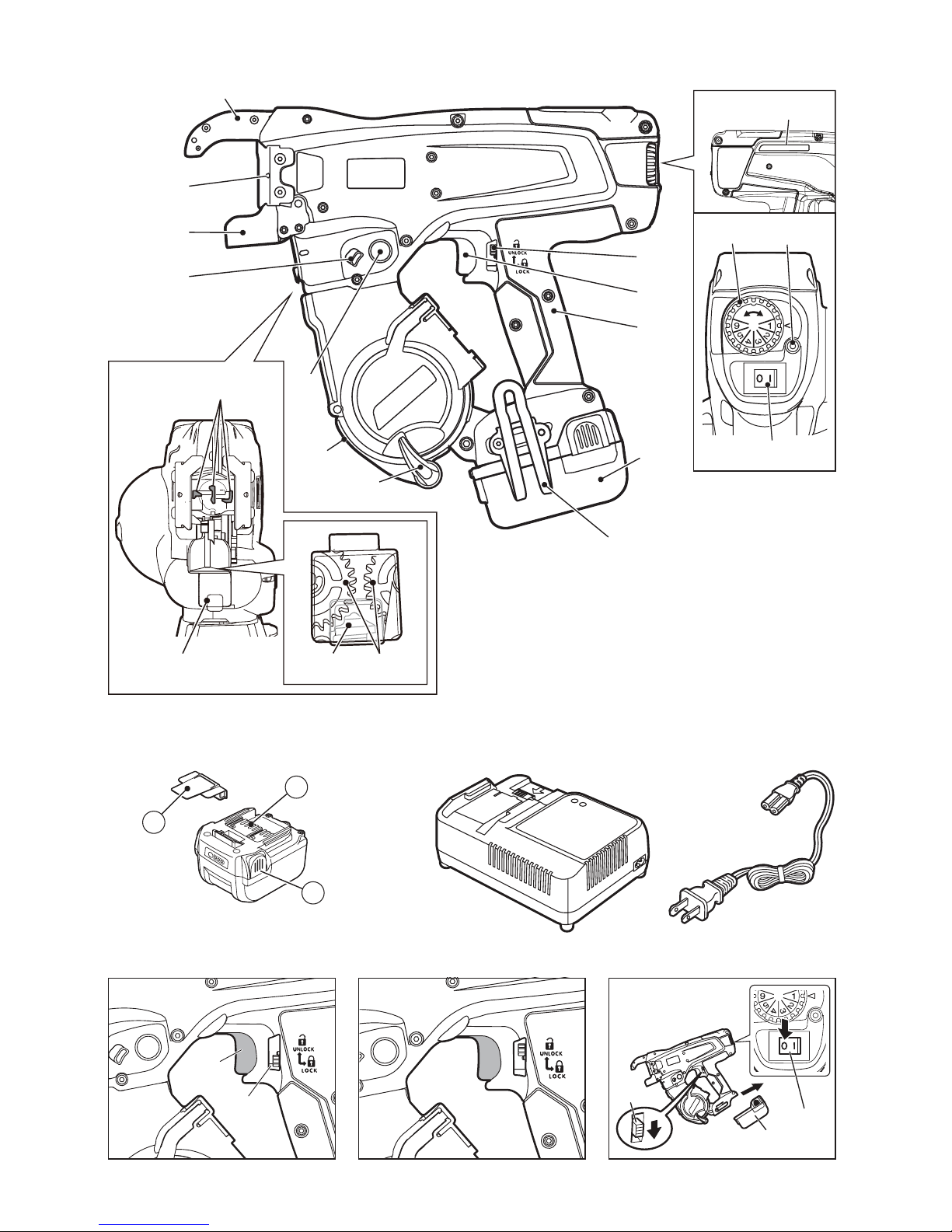
1. NAME OF PARTS
Fig.1
Fig.2
Fig.3
Refer to the JC925 operating and maintenance manual.
Fig.12
Fig.13
2. LIST OF CONTENTS
• MAX Rebar Tying tool / RB441T
• Lithium ion Battery pack / JPL91440A
• Lithium ion Battery charger / JC925
•Power cord
• INSTRUCTION MANUAL AND SAFETY INSTRUCTIONS (This book)
1 Arm
2 Trigger lock
3 Trigger
4 Grip
5 Battery pack
6 Magazine stopper
7 Magazine
8 Release button
9 Release stopper
0 Curl guide
a Center mark
b Serial number
c Torque dial
d LED
e Main switch
f Hook
g Window
h Feeding gear
i Wire guide
j Belt hook
k Pack cap
l Terminal
m Latch
n Magazine cover
o Holding slot
Page 7
7
3. GENERAL POWER TOOL
SAFETY WARNINGS
1. WORK AREA SAFETY
• Keep work area clean and well lit.
Cluttered or dark areas invite accidents.
• Do not operate power tools in
explosive atmospheres, such as in the
presence of flammable liquids, gases
or dust. Power tools create sparks which
may ignite the dust or fumes.
• Keep children and bystanders away
while operating a power tool.
Distractions can cause you to lose
control.
2. ELECTRICAL SAFETY
• Power tool plugs must match the
outlet. Never modify the plug in any
way. Do not use any adapter plugs with
earthed (grounded) power tools.
Unmodified plugs and matching outlets
will reduce risk of electric shock.
• Avoid body contact with earthed or
grounded surfaces, such as pipes,
radiators, ranges and refrigerators.
There is an increased risk of electric
shock if your body is earthed or grounded.
• Do not expose power tools to rain or
wet conditions. Water entering a power
tool will increase the risk of electric shock.
• Do not abuse the cord. Never use the
cord for carrying, pulling or
unplugging the power tool. Keep cord
away from heat, oil, sharp edges or
moving parts. Damaged or entangled
cords increase the risk of electric shock.
•
When operating a power tool outdoors,
use an extension cord suitable for
outdoor use.
Use of a cord suitable for
outdoor use reduces the risk of electric
shock.
• If operating a power tool in a damp
location is unavoidable, use a residual
current device (RCD) protected
supply. Use of an RCD reduces the risk
of electric shock.
3. PERSONAL SAFETY
•
Stay alert, watch what you are doing and
use common sense when operating a
power tool. Do not use a power tool while
you are tired or under the influence of
drugs, alcohol or medication.
A moment
of inattention while operating power tools
may result in serious personal injury.
• Use personal protective equipment.
Always wear eye protection. Protective
equipment such as dust mask, non-skid
safety shoes, hard hat, or hearing
protection used for appropriate conditions
will reduce personal injuries.
• Prevent unintentional starting. Ensure
the switch is in the off-position before
connecting to power source and/or
battery pack, picking up or carrying
the tool. Carrying power tools with your
finger on the switch or energising power
tools that have the switch on invites
accidents.
• Remove any adjusting key or wrench
before turning the power tool on.
A wrench or a key left attached to a
rotating part of the power tool may result
in personal injury.
• Do not overreach. Keep proper footing
and balance at all times. This enables
better control of the power tool in
unexpected situations.
• Dress properly. Do not wear loose
clothing or jewelry. Keep your hair,
clothing and gloves away from moving
parts. Loose clothes, jewelry or long hair
can be caught in moving parts.
• If devices are provided for the
connection of dust extraction and
collection facilities, ensure these are
connected and properly used. Use of
dust collection can reduce dust-related
hazards.
4. POWER TOOL USE AND CARE
• Do not force the power tool. Use the
correct power tool for your
application. The correct power tool will
do the job better and safer at the rate for
which it was designed.
READ ALL SAFETY WARNINGS AND ALL
INSTRUCTIONS.
Failure to follow the warnings and instructions
may result in electric shock, fire and/or
serious injury. Save all warnings and
instructions for future reference. The term
"power tool" in the warnings refers to your
mains-operated (corded) power tool or
battery-operated (cordless) power tool.
WARNING
Page 8

8
• Do not use the power tool if the switch
does not turn it on and off. Any power
tool that cannot be controlled with the
switch is dangerous and must be
repaired.
• Disconnect the plug from the power
source and/or the battery pack from
the power tool before making any
adjustments, changing accessories, or
storing power tools. Such preventive
safety measures reduce the risk of
starting the power tool accidentally.
• Store idle power tools out of the reach
of children and do not allow persons
unfamiliar with the power tool or these
instructions to operate the power tool.
Power tools are dangerous in the hands
of untrained users.
• Maintain power tools. Check for
misalignment or binding of moving
parts, breakage of parts and any other
condition that may affect the power
tool's operation. If damaged, have the
power tool repaired before use. Many
accidents are caused by poorly
maintained power tools.
• Keep cutting tools sharp and clean.
Properly maintained cutting tools with
sharp cutting edges are less likely to bind
and are easier to control.
• Use the power tool, accessories and
tool bits etc. in accordance with these
instructions, taking into account the
working conditions and the work to be
performed. Use of the power tool for
operations different from those intended
could result in a hazardous situation.
5. BATTERY TOOL USE AND CARE
• Recharge only with the charger
specified by the manufacturer. A
charger that is suitable for one type of
battery pack may create a risk of fire when
used with another battery pack.
• Use power tools only with specifically
designated battery packs. Use of any
other battery packs may create a risk of
injury and fire.
• When battery pack is not in use, keep
it away from other metal objects, like
paper clips, coins, keys, nails, screws
or other small metal objects, that can
make a connection from one terminal
to another. Shorting the battery terminals
together may cause burns or a fire.
• Under abusive conditions, liquid may
be ejected from the battery; avoid
contact. If contact accidentally occurs,
flush with water. If liquid contacts
eyes, additionally seek medical help.
Liquid ejected from the battery may cause
irritation or burns.
6. SERVICE
•
Have your power tool serviced by a
qualified repair person using only
identical replacement parts.
This will
ensure that the safety of the power tool is
maintained.
• Do not use the power tool in the rain, where
water is splashing, in a wet place, or in a
damp place. Using the tool in these or similar
conditions will increase the risk of electric
shock, dangerous malfunction, and
overheating.
• DO NOT DISPOSE OF BATTERY PACKS/
BATTERIES INTO FIRE OR WATER. Battery
packs/batteries should be collected, recycled
or disposed of in an environmental-friendly
manner.
• PROTECT THE BATTERY AGAINST HEAT,
ALSO AGAINST CONTINUOUS SUN
IRRADIATION AND FIRE. There is danger of
explosion.
• CHARGE THE BATTERY PACK IN A
TEMPERATURE RANGE 41°F (5°C) TO
104°F (40°C).
• The product you have purchased is
powered by a Li-ion battery which is
recyclable. At the end of its useful life,
under various state and local laws, it is
illegal to dispose of this battery into your
municipal waste stream. Please call 1-8008-BATTERY for information on how to
recycle this battery.
Page 9

9
4. RB441T SAFETY
FEATURES
1. INSPECT THE PARTS BEFORE
MOUNTING THE BATTERY PACK
• Examine the screws to make sure they are
securely tightened.
Incomplete tightening may result in an
accident or breakage. If a screw is loose,
retighten it completely.
• Inspect parts for damage.
Parts will wear over periods of use. Look
also for missing and defective parts and for
parts of poor quality. If a part must be
replaced or repaired, purchase the
replacement part at the dealer where the
tool was purchased or MAX CO., LTD.
authorized distributors.
Use only genuine authorized replacement
parts.
2. SET THE MAIN SWITCH (FIG.6.e) AT
"OFF", THE TRIGGER LOCK (FIG.6.2)
AT "LOCK" AND REMOVE THE BATTERY
PACK (FIG.6.5), WHEN CHANGING THE
BATTERY PACK, REPLACING OR
ADJUSTING THE TIEWIRE,
ABNORMALITIES OCCUR, AND THE
TOOL IS NOT BEING USED
Leaving the tool switched on in these
situations may cause breakdowns or
damage.
3. KEEP FINGERS AND BODY PARTS
CLEAR BETWEEN THE ARM AND CURL
GUIDE AT ALL TIMES (FIG.23)
Failure to do so may result in serious injury.
4. KEEP FINGERS AND BODY PARTS
AWAY FROM THE TIEWIRE WHEN TOOL
IS IN OPERATION
Failure to do so may result in serious injury.
5. DO NOT POINT THE TOOL AT ANYONE
Personal injury may result if the tool catches
an operator or anyone working near him/her.
While working with the tool, be extremely
careful not to bring hands, legs, and other
body parts near the arm of the tool.
6. WHEN THE TOOL IS NOT IN OPERATION
KEEP YOUR FINGERS OFF THE
TRIGGER
Failure to do so may cause accidental tying,
leading to serious injury.
7. NEVER OPERATE THE TOOL UNDER
ANY ABNORMAL CONDITION
If the tool is not in good working order, or if
any abnormal condition is noticed, switch it off
immediately (set the Main switch at "OFF"),
lock the Trigger and have it examined and
repaired.
8. AFTER BATTERY INSTALLATION IF THE
TOOL OPERATES WITHOUT THE
TRIGGER BEING PULLED OR THE
OPERATOR NOTICES UNUSUAL HEAT,
SMELL, OR SOUND, DISCONTINUE
OPERATION
Failure to do so may lead to serious injury.
Return to dealer for safety inspection.
9. NEVER MODIFY THE TOOL
Modifying the tool will impair performance and
operating safety. Any modification may lead to
serious injury and void the tool warranty.
10. MAINTAIN THE TOOL IN GOOD
OPERATING CONDITION
To secure operating safety and ensure top
performance, keep the tool free of wear and
damage. Also keep the tool's hand grip dry
and clean, especially free of oil and grease.
11. USE ONLY THE AUTHORIZED BATTERY
PACK
If the tool is connected to a power supply
other than the authorized pack, such as a
rechargeable battery, a dry cell, or a storage
battery for use in automobiles, the tool may
be damaged, break down, overheat, or even
catch on fire. Do not connect this tool to any
power supply except the authorized battery
pack.
12. TO ENSURE MAXIMUM PERFORMANCE,
FULLY CHARGE THE BATTERY BEFORE
USE
A new battery pack or one not used for
extended periods may have self-discharged
and thus may need recharging to restore it to
a fully charged condition. Before operating
the tool, make sure to charge the Battery pack
with the designated MAX Battery charger.
13. BATTERY CHARGING PRECAUTION
13-1 Use only MAX Battery charger and
MAX Battery pack.
Failure to do so may cause the Battery
to overheat or catch fire leading to
serious injury.
Page 10

10
13-2 Charge the Battery from an AC 120V
wall sockets.
Failure to do so may result in
overheating, or inadequate charging
possibly causing serious injury.
13-3 Never use a transformer.
13-4 Never connect the Battery charger to
an engine generator direct-current
power supply.
The charger will break down or be
damaged from burning.
13-5 Avoid charging the Battery pack in
the rain, in a damp place, or where
water is splashing.
Charging a damp or wet Battery pack
will cause an electric shock or a short
circuit that may lead to damage from
burning and even the tool catching on
fire.
13-6 Do not touch the power cord or plug
with a wet hand or glove.
This may cause injury from electric
shock.
13-7 Do not put a cloth or any other cover
on the Battery charger while the
Battery pack is being charged.
This will cause overheating and
damage from burning, or the Charger
may even catch fire.
13-8 Keep the Battery pack and Battery
charger away from heat and flames.
13-9 Do not charge the Battery pack near
flammable materials.
13-10 Charge the Battery pack in a well
ventilated place.
Avoid charging the Battery pack where
it will be in direct sunlight.
13-11 Charge the Battery pack in a
temperature range of 41°F (5°C) to
104°F (40°C).
13-12 Avoid continual use of the Battery
charger.
Rest the Charger for 15 minutes
between charges to avoid functional
trouble with the unit.
13-13 Any objects that block the
ventilation holes or Battery pack
receptacle may cause electric shock
or functional troubles.
Operate the charger free of dust or
other foreign materials.
13-14 Handle the power cord carefully.
Do not carry the Battery charger by its
power cord. Do not use the power cord
to disconnect it from a wall socket; this
will damage the cord and break the
wires or cause a short circuit. Do not let
the power cord contact sharp edged
tools, hot materials, oil, or grease. A
damaged cord must be repaired or
replaced.
13-15 Do not charge non rechargeable
batteries with this charger.
13-16 This charger is not intended for use
by children or disabled persons
without supervisor.
13-17 Children should be supervised to
ensure that they do not play with the
charger.
13-18 Put a Pack cap (Fig.2.k) on the
Terminal (Fig.2.l) of the Battery
pack.
When the Battery pack is not in use, put
a Pack cap on its Terminal to prevent
short circuits.
13-19 Do not let the Terminal (metal
component) of the Battery pack
short-circuit.
A short circuit in the Terminal will
generate a large current, causing to
overheat the Battery pack and become
damaged.
13-20 Do not leave or store the tool in a
vehicle or in direct sunlight during
summer. Leaving the tool in high
temperature conditions may cause
the Battery pack to deteriorate.
13-21 Do not store a fully discharged
Battery pack. If a fully discharged
Battery pack is removed from the
system and left for a long period of
time, it may become damaged.
Recharge the battery immediately
when it has been discharged.
14. WEAR SAFETY GLOVES WHILE
OPERATING THE TOOL
The finish tie has sharp edges. To avoid
serious injures, be careful not to touch the
sharp edges.
15. PRIOR TO USING THE TOOL
(Fig.4 and 5) Make sure that the safety
features function properly. If they do not,
avoid using the tool.
Page 11

11
5. TOOL SPECIFICATIONS AND TECHNICAL DATA
<BATTERY CHARGER>
<BATTERY PACK>
PRODUCT DESCRIPTION MAX Rebar Tying tool “TWINTIER”
PRODUCT NO. RB441T
DIMENSIONS (Battery pack included) (H)11-1/2" (295mm) x (W)4-7/8" (125mm) x (L)13" (330mm)
WEIGHT (Battery pack included) 5.6lbs (2.5kg)
BATTERY Lithium ion Battery pack / JPL91440A
OPERATING TEMPERATURE 14°F to 104°F (-10°C to 40°C)
HUMIDITY 80% RH or less
PRODUCT DESCRIPTION Lithium ion Battery charger
PRODUCT NO. JC925
INPUT AC120V 60Hz 2.6A 160W
OUTPUT DC14.4V 7.5A, DC18V 5.4A, DC25.2V 4.5A
WEIGHT 3.3lbs (1.5kg)
OPERATING TEMPERATURE RANGE 41°F to 104°F (5°C to 40°C)
OPERATING HUMIDITY RANGE 80% RH or less
PRODUCT DESCRIPTION Lithium ion Battery pack
PRODUCT NO. JPL91440A
NOMINAL VOLTAGE DC14.4V (3.6V x 4cells)
NOMINAL CAPACITY 3.9Ah (3,900mAh)
CHARGING TIME Quick charging – Approx. 33min.(Approx. 90% of capacity)
Full charging – Approx. 45min.(100% of capacity)
ACCESSORIES Pack cap
WEIGHT 1.1lbs (0.5kg)
CHARGING TEMPERATURE 41°F to 104°F (5°C to 40°C)
OPERATINGTEMPERATURE RANGE 32°F to 104°F (0°C to 40°C)
OPERATING HUMIDITY RANGE 80% RH or less
TIES PER CHARGE Approx. 4,000 ties (*under the following conditions: normal temperature,
unused, full-charged battery and #4 x #4 (13mm x 13mm) rebars)
Page 12

12
6. TECHNICAL DATA
6-1 NOISE
Measured value according to EN 60745:
A-weighted sound pressure level (LpA): 79 dB
Uncertainty (KpA):3dB
A-weighted sound power level (LWA): 79 dB
Uncertainty (KWA):3dB
6-2 VIBRATION
Measured value according to EN 60745:
Vibration total values (ah): 0.5 m/s
2
Uncertainty (K): 0.1 m/s
2
• The declared vibration emission value has been measured in accordance with the standard test method and may
be used for comparing one tool with another.
• The declared vibration emission value may also be used in a preliminary assessment of exposure.
• The vibration emission during actual use of the power tool can differ from the declared emission value depending
on the ways in which the tool is used.
• Be sure to identify safety measures to protect the operator that are based on an estimation of exposure in the
actual conditions of use (taking account of all parts of the operating cycle such as the times when the tool is
switched off and when it is running idle in addition to the trigger time).
6-3 RADIATED EMISSION 30-1000 MHZ Class A
This is a class A product. In a domestic environment this product may cause radio interference in which case the
user may be required to take adequate measures.
6-4 Overvoltage category - category 1 according to IEC 60664-1
6-5 Pollution degree - degree 4 according to IEC 60664-1
6-6 Design guidelines – Machinery directive annex 1, EN60745-1, EN60745-2-18
7. PRODUCTION YEAR
This product bears production number in the body (Fig.1.b). The two digits of the number from left
indicates the production year.
WARNING
WARNING
(Example)
17526035D
Year 2017
Page 13
13
8. WIRE SPECIFICATION
*RB441T is not compatible with TW898 series or TW1525 series.
9. APPLICATIONS
• Precast concrete panel
• Building foundation
• Commercial building
• Road & Bridge
• Floor heating pipe
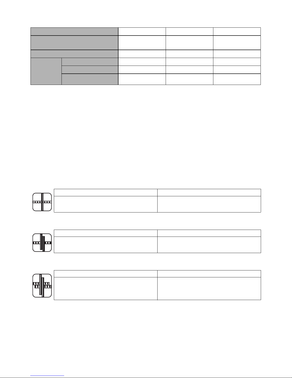
10.APPLICABLE REBAR SIZE
■ 2 rebars combination
■ 3 rebars combination
■ 4 rebars combination
TIEWIRE TW1061T TW1061T-PC TW1061T-EG
TYPE OF WIRE
Annealed wire Poly-coated wire
Electro-galvanized
wire
DIAMETER 19GA (1.0mm) 19GA (1.1mm) 19GA (1.0mm)
TIES/COIL
#3 × #3 (10 mm × 10 mm)
Approx. 265 ties Approx. 230 ties Approx. 265 ties
#4 × #4 (13 mm × 13 mm)
Approx. 240 ties Approx. 210 ties Approx. 240 ties
#7 × #5 × #5
(22 mm × 16 mm × 16 mm)
Approx. 170 ties Approx. 150 ties Approx. 170 ties
Minimum Maximum
#3 × #3 (10mm × 10mm)
#7 × #7 (22mm × 22mm)
#8 × #6 (25mm × 19mm)
Minimum Maximum
#3 × #3 × #3 (10mm × 10mm × 10mm)
#7 × #5 × #5 (22mm × 16mm × 16mm)
#8 × #4 × #4 (25mm × 13mm × 13mm)
Minimum Maximum
#3 × #3 × #3 × #3
(10mm × 10mm × 10mm × 10mm)
#5 × #5 × #4 × #4
(16mm × 16mm × 13mm × 13mm)
Page 14
14
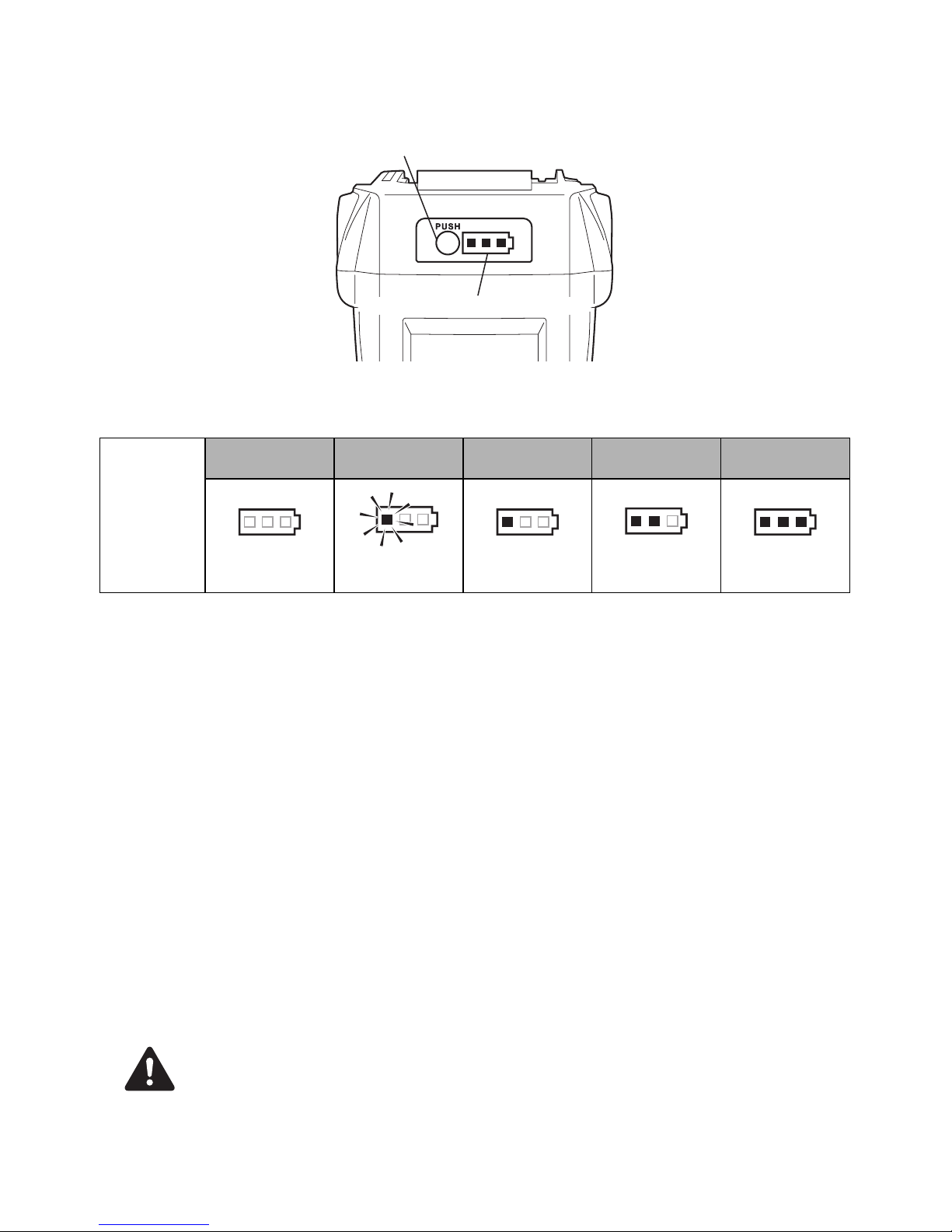
11.BATTERY INSTRUCTIONS
About the Battery Level Indicator
(1) To check the battery level (excluding while charging or while operating the charging
tool), press the Battery level check button.
(2) The Battery level gauge is on according to the battery level.
Service Life of the Battery pack
If any condition described below is observed, the Battery pack is at the end of its service life. Replace it
with a new one.
Although the Battery pack has been properly charged (fully charged), a great drop in tying time has been
noticed.
• Do not charge the Battery pack when this happens. If the motor’s rotational speed slows down,
the power of the Battery pack is considered to be nearly depleted. Using the tool more will
cause it to overdischarge, resulting in a shortened service life of the Battery pack and also in
functional trouble of the tool’s main body.
• Do not use a Battery pack when its service life is finished.
This will cause functional trouble in the tool’s main body. Also charging a Battery pack that is
out of service life will lead to functional trouble in the Charger.
Recycling a Li-ion Battery
The MAX battery pack uses a Li-ion battery, it may be illegal to dispose of this Battery into the municipal
waste system. Check with your local solid waste officials for details in your area for recycling options or
proper disposal.
When disposing of the Battery pack, make sure to put a Pack cap on its Terminal (with insulating
tape securing it) to prevent short circuits.
Battery level
gauge
Battery level:
0%
Battery level:
about 0 to 10%
Battery level:
about 10 to 40%
Battery level:
about 40 to 70%
Battery level:
about 70 to 100%
All indicators
OFF
One red
indicator blinks
One red
indicator ON
Two red
indicators ON
Three red
indicators ON
Battery level check button
Battery level gauge
NOTICE
CAUTION
Page 15

15
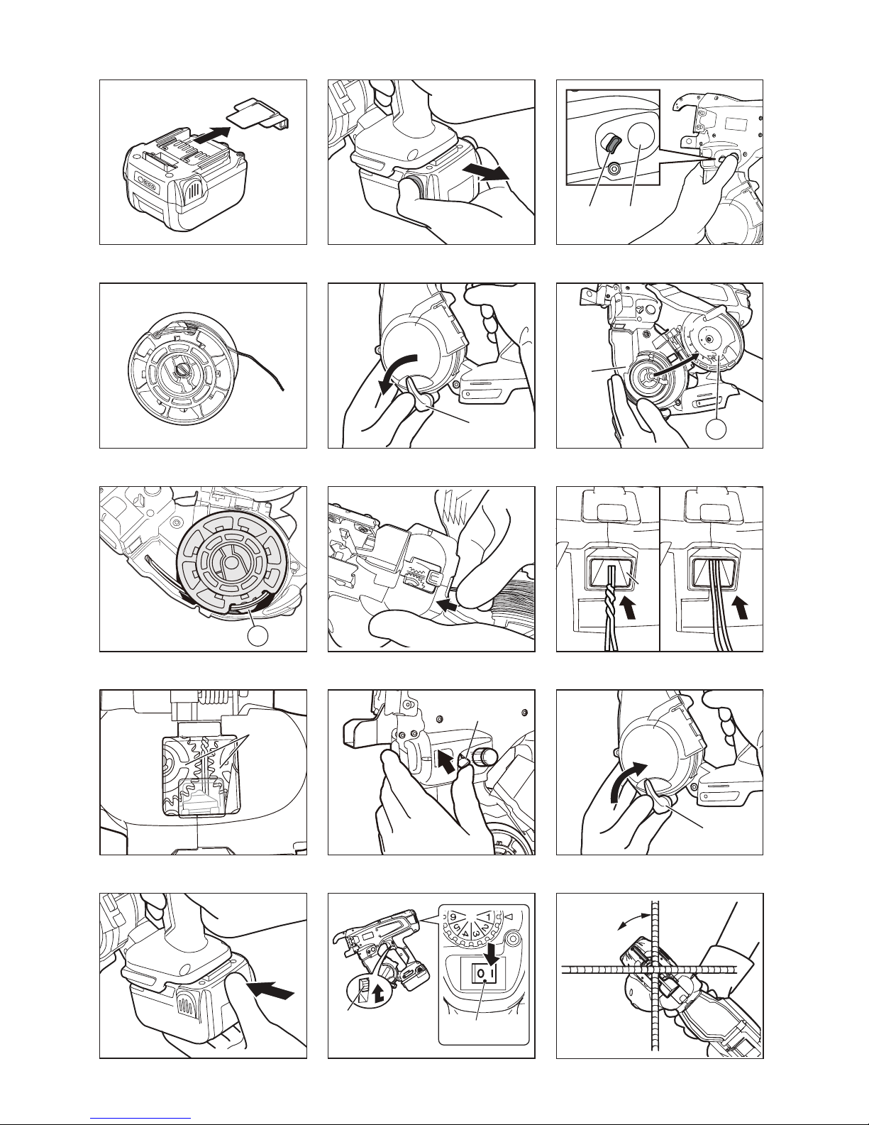
12. OPERATING INSTRUCTIONS
1. How to set the Tiewire
(Fig.6) Set the Main switch (e) at "OFF", the
Trigger lock (2) at "LOCK" and remove the
Battery pack (5).
• Be careful not to drop or give a strong
impact to the Tiewire. It may cause the
damage and the malfunction of the tool.
• Beware of the tip of the wire when you pick
up the Tiewire. It might cause an injury.
1-1 (Fig.9) Press the Release button (8) of this
tool, and confirm that the Release button is
caught in the Release stopper (9).
1-2 (Fig.10) Stretch out the tip of the wound
Tiewire.
BE SURE TO USE ONLY THE SPECIFIED
TIEWIRE (MAX TW1061T Series).
The use of binding wire that has not been
specified may cause breakdown of this tool.
Therefore, be sure only to use the specified MAX
TW1061T series.
RB441T is not compatible with TW898 series or
TW1525 series.
DO NOT USE RUSTY WIRE.
The use of the rusty wire may cause functional
trouble of the tool.
1-3 (Fig.11) Rotate the Magazine stopper (6)
45° counterclockwise.
1-4 (Fig.12,13) Open the Magazine cover (n)
and set the Tiewire in the Magazine (7) with
the Holding slot (o) side of the reel facing
up.
1-5 (Fig.14) Grasp the tool with the left hand,
hold the tip of the wire with the right hand,
and remove the wire from the Holding slot.
The 2 wire tips of new Tiewire are twisted.
1-6 (Fig.15) Straighten out the tip of the wire,
and insert the twisted wire into the Wire
guide (i) parallel.
1-7 (Fig.16) Confirm through the Window that
the twisted part of wire has reached past two
Feeding gears (h).
1-8 (Fig.17) Press the Release stopper (9) up,
and confirm that the Release button has
been raised up.
1-9 (Fig.18) Close the Magazine cover and
rotate the Magazine stopper 45° clockwise.
If the Window is dirty
Open the Window (Fig.1.g) and wipe off the dirt
on the inside of the Window with a cloth. Close
the Window again after cleaning to ensure that
foreign objects will not be able to enter the tool.
2. How to operate RB441T
(Fig.6) Set the Main switch (e) at "OFF", the
Trigger lock (2) at "LOCK" and remove the
Battery pack (5).
2-1 (Fig.19) Mount the Battery pack on the tool's
main body until a click is heard.
2-2 (Fig.20) When Main switch (e) is turned
"ON", the Hook (Fig.1.f) of the tip rotates
automatically for initializing, absolutely do
not bring your fingers close to any rotating
and moving part. Set the Main switch at "ON"
and the trigger lock (2) at "UNLOCK".
2-3 (Fig.21) Tilt the tool 45° angle to the crossed
rebars.
2-4 (Fig.22) Align the Center mark (a) to the
center of the crossed rebars.
2-5 Once pull the Trigger, the tool automatically
completes a series of tying actions (feeding,
cutting, gripping and tying).
• (Fig.23) When the Main switch (Fig.1.e) is
turned "ON", the Hook (Fig.1.f) of the tip
rotates automatically for initializing,
absolutely do not bring your fingers close
to any rotating and moving part.
• Do not touch any rotating and moving part
such as hook of the tip or the Tiewire
during the tying work (while the machine is
operating).
3. How to remove the Tiewire
(Fig.6) Set the Main switch (e) at "OFF", the
Trigger lock (2) at "LOCK" and remove the
Battery pack (5).
3-1 (Fig.9) Press the Release button (8) of the
tool and confirm that the Release button is
caught in the Release stopper (9).
CAUTION
NOTICE
WARNING
Page 16

16
3-2 (Fig.11) Rotate the Magazine stopper (6) to
open the Magazine cover.
3-3 (Fig.24) Remove the Tiewire from the
Magazine.
3-4 (Fig.25) Remove the wire with the plastic
piece from the Wire guide.
4. When the Tiewire runs out
(Fig.26) The plastic piece comes off when it is used
up normally, and can be discarded separately as
plastic and metal wire. (About 8" (20cm) remains
after normal use)
(Fig.6) Set the Main switch (e) at "OFF", the
Trigger lock (2) at "LOCK" and remove the Battery
pack (5).
5. Tension adjustment
(Fig.27.c) This dial allows you to adjust wire
tension torque slightly. To increase the tension,
turn it in the counterclockwise. To decrease the
tension, turn it in the clockwise.
6. Auto Power-off feature
This tool has "Auto Power-off" feature, which
saves the power consumption of the Battery
when the tool is not operated.
If the tool is not operated for 30 minutes, the tool
is automatically turned off. When the power is
turned off automatically, turn the Main switch
OFF and ON again to operate the tool.
7. For proper tightness
7-1 (Fig. 21) Tilt the tool 45° angle to the crossed
rebars.
7-2 (Fig.22) Align the Center mark (a) to the
center of the crossed rebars.
7-3 (Fig.28) Apply the tool perpendicularly to the
surface of the crossed rebars.
During tool operation
Do not move the tool during tying operation until
the tool stops tying automatically.
7-4 (Fig.29) Tie in alternate direction.
7-5 (Fig.30) Cross tying.
Bent the knot of the first tie before making
the second tying.
8. How to reload previously used
Tiewire
(Fig.31) Without twisting the 2 wires, insert them
into the Wire guide (i).
9. (Fig.32) How to set and remove
the belt hook to the tool
The belt hook can be installed either on the right
or the left side of the tool.
Installing/Removing the belt hook
(Installing)
Insert the belt hook into the slot on the tool.
Secure it with a screw.
(Removing)
Loosen a screw, and then remove the belt hook.
• When using the belt hook or changing the
position, set the Main switch (e) at "OFF",
the Trigger lock (2) at "LOCK" and remove
the Battery pack (5).
Failure to do so may cause the tool to start
accidentally, which may cause an accident.
• Before using the belt hook, make sure that
the hook is securely installed on the tool.
Using an improperly installed belt hook may
cause personal injury.
• Securely tighten the designated genuine
screw.
If the screw become loose due to vibration, etc.
generated by operation, the loose screw may
cause a dropping accident.
• When using the belt hook, the tool must be
hooked securely to prevent it from falling.
If the tool falls, it could result in an accident.
WARNING
Page 17

17
13.STORAGE
Do not store the tool in a cold weather
environment. Keep the tool in a warm area.
When not in use, the tool should be stored in a
warm and dry place. Keep out of reach of
children.
REMOVE REEL OF TIEWIRE
When you have finished the Tiewire, remove the
reel from the tool.
STORE THE TOOL
When you have finished tying work or when the
tool will not be used for a while, set the Main
switch (Fig.1.
e
) at "OFF", the Trigger lock
(Fig.1.
2
) at "LOCK" and remove the Battery pack
(Fig.1.
5
). The tool and accessories should be
stored in a well-ventilated dry place where the
temperature will not exceed 104°F (40°C).
The Battery pack with the Pack cap (Fig.2.
k
) to
prevent short circuits should be stored in a wellventilated dry place where the temperature will
not exceed 86°F (30°C).
Page 18

18
14.WARNING BUZZERS AND PROCEDURES TO FOLLOW
This tool sounds warning buzzers for the conditions described below. If the buzzer sounds, follow
procedures according to the conditions described below.
<Buzzer types and procedures to follow>
<When no buzzer sounds but malfunction is suspected>
• If the conditions described below occur, set the Main switch (Fig.1.e) at "OFF", the Trigger
lock (Fig.1.
2
) at "LOCK" and remove the Battery pack (Fig.1.5) before following procedures.
• Do not touch the tying or rotating parts at the tip when setting the Main switch at "ON" under
any circumstances.
Buzzer types Possible cause Procedures to follow
Once (Pi, pi, pi...)
Wire is jammed in the Hook
(Fig.1.f)
Check whether the wire or anything else
is caught in the Hook
Motor is hot Let the tool rest and cool down
Twice (Pipi, pipi, pipi...)
Low battery Charge the Battery pack
Battery pack is not fully inserted Insert the Battery pack properly
Three times
(Pipipi, pipipi, pipipi...)
Tiewire is used up Replace with a new Tiewire
Tiewire is jammed
Open the Magazine cover (Fig.12.n)
and fix the jammed wire
Continuous high pitched
beep (Piii...)
Curl guide (Fig.1.0) is open Confirm supported rebar diameters
Single-short and
continuous high & low
pitched chime
(Pipo / Pii poh Pii poh...)
Internal structure; defect in internal
driving mechanism
Immediately discontinue operation and
set the Main switch (Fig.6.e) at "OFF",
the Trigger lock (Fig.6.2) at "LOCK"
and remove the Battery pack (Fig.6.5)
before consulting. Then contact the
dealer where the tool was purchased or
MAX CO., LTD. authorized distributors.
Symptom Possible cause Procedures to follow
Main switch is "ON" but
does not work
Dead battery
Switch to a new battery and confirm
whether it works
Product does not
function
Auto Power-off feature operated
Try switching the Main switch (Fig.1.e)
from OFF to ON
Tying is not proper Wire is touching rebars while tying Tie so that wire is not touching rebars
Twisted off
Rebar size is not applicable Use with supported rebars diameters
Tension adjustment dial is too tight
Adjust tension adjustment dial
(Fig.1.c)
Tension is too loose
The tied section is not on the
Center mark (Fig.22.a)
Align the Center mark to the center of
the crossed rebars and pull the trigger
Rebar size is not applicable Use with supported rebar diameters
Tension adjustment dial is too
loose
Adjust tension adjustment dial tighter
(Fig.1.c)
Tie form is notably
deformed
Worn or broken parts
Immediately discontinue operation and
set the Main switch (Fig.6.e) at "OFF",
the Trigger lock (Fig.6.2) at "LOCK"
and remove the Battery pack (Fig.6.5)
before consulting. Then contact the
dealer where the tool was purchased or
MAX CO., LTD. authorized distributors.
Increased frequency of
jamming
WARNING
Page 19

19
ÍNDICE
1. NOMBRE DE LAS PIEZAS ........................................................ 20
2. LISTA DE CONTENIDOS ........................................................... 20
3. ADVERTENCIAS GENERALES DE SEGURIDAD SOBRE
LA HERRAMIENTA ELÉCTRICA............................................... 21
4. ADVERTENCIAS DE SEGURIDAD RELATIVAS A LA
RB441T ....................................................................................... 23
5. DATOS TÉCNICOS Y ESPECIFICACIONES DE LA
HERRAMIENTA.......................................................................... 26
6. DATOS TÉCNICOS .................................................................... 27
7. AÑO DE PRODUCCIÓN ............................................................. 27
8. ESPECIFICACIONES DEL ALAMBRE ...................................... 28
9. APLICACIONES ......................................................................... 28
10. TAMAÑO DE ARMADURA APLICABLE ................................... 28
11. INSTRUCCIONES DE LA BATERÍA.......................................... 29
12. INSTRUCCIONES DE FUNCIONAMIENTO............................... 30
13. ALMACENAMIENTO.................................................................. 32
14. ALARMAS ACÚSTICAS Y PROCEDIMIENTOS A SEGUIR ..... 33
DEFINICIONES DE LAS SEÑALES INDICATIVAS
ADVERTENCIA: indica una situación peligrosa que, si no se evita, puede provocar lesiones graves o
incluso la muerte.
PRECAUCIÓN: indica una situación peligrosa que, si no se evita, puede provocar lesiones leves o
moderadas.
AVISO: indica un mensaje relativo a posibles daños materiales.
ESPAÑOL
MANUAL DE INSTRUCCIONES E INSTRUCCIONES DE SEGURIDAD
Traducción de las
instrucciones originales
Page 20

20
1. NOMBRE DE LAS PIEZAS
Fig.1
Fig.2
Fig.3
Consulte el manual de funcionamiento y mantenimiento del cargador JC925.
Fig.12
Fig.13
2. LISTA DE CONTENIDOS
• Atadora de armaduras de refuerzo MAX / RB441T
• Paquete de baterías de ion litio / JPL91440A
• Cargador de baterías de ion litio / JC925
• Cable de alimentación eléctrica
• MANUAL DE INSTRUCCIONES E INSTRUCCIONES DE SEGURIDAD (este libro)
1 Brazo
2 Seguro del disparador
3 Disparador
4 Empuñadura
5 Paquete de baterías
6 Bloqueador del
compartimento de bobina
7 Compartimento de bobina
8 Botón de desbloqueo
9 Bloqueo
0 Guía de curvado
a Marca central
b Número de serie
c Disco selector del par
d LED
e Interruptor principal
f Gancho
g Ventanilla
h Engranaje de alimentación
i Guía del alambre
j Gancho para cinturón
k Tapa del paquete
l Terminal
m Cierre
n Cubierta del
compartimento de bobina
o Ranura de sujeción
Page 21

21
3. ADVERTENCIAS
GENERALES DE SEGURIDAD
SOBRE LA HERRAMIENTA
ELÉCTRICA
1. SEGURIDAD EN LA ZONA DE TRABAJO
• Mantenga la zona de trabajo limpia y
bien iluminada. Las zonas de trabajo
abarrotadas u oscuras propician los
accidentes.
• No utilice la herramienta eléctrica en
atmósferas explosivas, como por
ejemplo en presencia de líquidos
inflamables, gases o polvo. Las
herramientas eléctricas generan chispas
que pueden prender fuego al polvo o a los
humos.
• Mantenga alejados a los niños y a los
curiosos mientras utiliza la
herramienta eléctrica. Las distracciones
pueden hacerle perder el control.
2. SEGURIDAD ELÉCTRICA
• Los enchufes de las herramientas
eléctricas deben guardar
correspondencia con la toma de
corriente. Nunca modifique el enchufe
de ninguna manera. No utilice ningún
enchufe adaptador con las
herramientas eléctricas conectadas a
tierra. Los enchufes sin modificaciones y
en correspondencia con las tomas de
corriente reducirán el riesgo de descarga
eléctrica.
•
Evite el contacto corporal con las
superficies conectadas a tierra, como
tuberías, radiadores, estufas y neveras.
Si su cuerpo está conectado a tierra el
riesgo de descarga eléctrica es mayor.
• No exponga las herramientas
eléctricas a la lluvia o la humedad. La
entrada de agua a una herramienta
eléctrica aumentará el riesgo de
descarga eléctrica.
• Trate el cable con cuidado. No lo use
nunca para trasladar, arrastrar o
desenchufar la herramienta eléctrica.
Mantenga el cable alejado del calor, el
aceite, los bordes cortantes y las
piezas móviles. Los cables dañados o
enredados aumentan el riesgo de
descarga eléctrica.
•
Cuando use una herramienta eléctrica
en el exterior, hágalo utilizando un
cable de extensión adecuado.
El uso de
un cable adecuado para utilización en el
exterior reduce el riesgo de descarga
eléctrica.
•
Si la utilización de una herramienta
eléctrica en un lugar mojado es
inevitable, use un dispositivo de
corriente residual (RCD) con suministro
protegido.
La utilización de un RCD
reduce el riesgo de descarga eléctrica.
3. SEGURIDAD PERSONAL
•
Cuanto utilice una herramienta eléctrica
permanezca alerta, preste atención a lo
que hace y aplique el sentido común. No
utilice una herramienta eléctrica si está
cansado o bajo los efectos de drogas,
bebidas alcohólicas o medicamentos.
Un
instante de descuido durante la utilización
de herramientas eléctricas puede provocar
graves lesiones personales.
•
Use equipo de protección personal. Use
siempre protección ocular.
El equipo de
protección, como máscara antipolvo,
zapatos de seguridad antideslizantes,
casco y protección auditiva, utilizado en las
condiciones apropiadas reducirá el riesgo
de lesiones personales.
• Prevenga la puesta en marcha
accidental. Antes de conectar la
herramienta a la red de alimentación
eléctrica y/o al paquete de baterías,
recogerla o trasladarla, asegúrese de
que el interruptor esté en la posición
"off" ("desconectado"). El traslado de
las herramientas eléctricas con el dedo
en el interruptor o con el interruptor en la
posición "on" propicia los accidentes.
• Antes de poner en marcha la
herramienta retire de la misma toda
llave de ajuste o llave inglesa.
Una llave inglesa o llave de ajuste sujeta
a una pieza giratoria de la herramienta
eléctrica puede provocar lesiones
personales.
LEA TODAS LAS INSTRUCCIONES Y
ADVERTENCIAS DE SEGURIDAD.
Si no respeta las advertencias e instrucciones,
pueden producirse descargas eléctricas,
incendios y/o lesiones graves.
Conserve
todas las advertencias e instrucciones
para futuras consultas.
El término
"herramienta eléctrica" indicado en las
advertencias se refiere a la herramienta
conectada (mediante cables) a la red eléctrica
o accionada por batería (inalámbrica).
ADVERTENCIA
Page 22

22
•
Utilice la herramienta sin extralimitarse.
Manténgase en todo momento en
equilibrio, con los pies bien apoyados
en el suelo.
De este modo podrá controlar
mejor la herramienta eléctrica en
situaciones imprevistas.
• Vístase adecuadamente. No use ropa
holgada ni joyas. Mantenga el cabello,
la ropa y los guantes alejados de las
piezas móviles. Las prendas holgadas,
las joyas o el cabello largo pueden quedar
atrapados en las piezas móviles.
• Si la herramienta tiene dispositivos
para recogida y extracción de polvo,
asegúrese de que están conectados y
se utilizan adecuadamente. El uso del
dispositivo de recogida de polvo puede
reducir los peligros relacionados con el
mismo.
4. UTILIZACIÓN Y CUIDADO DE LA
HERRAMIENTA ELÉCTRICA
• No fuerce la herramienta eléctrica. Use
la herramienta eléctrica adecuada a
sus necesidades. La herramienta
eléctrica adecuada hará mejor el trabajo y
de manera más segura a la velocidad
para la que fue diseñada.
• No use la herramienta eléctrica si el
interruptor no conmuta entre las
posiciones "on" ("conectado") y "off"
("desconectado"). Toda herramienta
eléctrica que no puede controlarse con el
interruptor es peligrosa y debe repararse.
• Desconecte el enchufe de la red
eléctrica y/o el paquete de baterías de
la herramienta antes de guardarla o de
realizar ajustes o cambios de
accesorios. Estas medidas de seguridad
preventivas reducen el riesgo de puesta
en marcha accidental de la herramienta
eléctrica.
• Guarde las herramientas eléctricas
fuera de uso alejadas del alcance de
los niños y no deje que las utilicen
personas no familiarizadas con las
mismas o con estas instrucciones. El
uso de herramientas eléctricas por
personas que carecen de la formación
necesaria resulta peligroso.
• Realice el mantenimiento de las
herramientas eléctricas. Compruebe
que las piezas móviles estén bien
alineadas y sujetas, y que ninguna
pieza esté dañada o en un estado que
pueda afectar al funcionamiento de la
herramienta eléctrica. Si detecta
alguna avería, haga reparar la
herramienta eléctrica antes de usarla.
El mantenimiento deficiente de las
herramientas eléctricas provoca muchos
accidentes.
• Mantenga las herramientas de corte
afiladas y limpias. Las herramientas de
corte adecuadamente mantenidas y con
los bordes afilados tienen menos
probabilidades de atascarse y son más
fáciles de controlar.
• Use la herramienta eléctrica, los
accesorios, las piezas, etc. de acuerdo
con estas instrucciones, teniendo en
cuenta las condiciones de trabajo y la
tarea que debe realizar. El uso de la
herramienta eléctrica para trabajos que
no sean los previstos podría provocar una
situación peligrosa.
5. UTILIZACIÓN Y CUIDADO DE LA
BATERÍA DE LA HERRAMIENTA
• Recargue la batería únicamente con el
cargador especificado por el
fabricante. Un cargador apto para un
determinado tipo de paquete de baterías
puede provocar riesgo de incendio si se
utiliza con otro tipo de paquete de
baterías.
• Use las herramientas eléctricas sólo
con los paquetes de batería diseñados
específicamente. El uso de cualquier
otro paquete de baterías puede provocar
riesgo de lesiones e incendio.
• Cuando el paquete de baterías esté
fuera de uso, manténgalo alejado de
otros objetos metálicos, como clips
para papeles, monedas, llaves, clavos,
tornillos u otros objetos metálicos
pequeños que pueden establecer la
conexión entre un terminal y otro. La
unión de los terminales de baterías puede
causar quemaduras o provocar un
incendio.
• En condiciones de uso inadecuadas la
batería puede proyectar líquido, cuyo
contacto es necesario evitar. Si
accidentalmente entra en contacto con
dicho líquido, lávese bien con agua. Si
el líquido entra en contacto con los
ojos, lávese con agua y acuda al
médico. El líquido proyectado por la
batería puede causar irritación o
quemaduras.
6. REPARACIÓN
•
La reparación de la herramienta eléctrica
debe confiarse a un técnico cualificado
que utilice únicamente las piezas de
recambio originales.
De esta manera se
garantizará la seguridad de la herramienta
eléctrica.
Page 23

23
• No use la herramienta eléctrica bajo la
lluvia, donde haya salpicaduras de agua, o
en un lugar húmedo o mojado. La utilización
de la herramienta en esas condiciones o
similares aumentará el riesgo de descarga
eléctrica, avería peligrosa y recalentamiento.
• NO ARROJE LAS BATERÍAS O PAQUETES
DE BATERÍAS AL FUEGO O AL AGUA. Las
baterías o paquetes de baterías deben
recogerse, reciclarse o eliminarse de una
manera que no afecte al medio ambiente.
• PROTEJA LA BATERÍA CONTRA EL
CALOR, LA IRRADIACIÓN SOLAR
CONTINUA Y EL FUEGO. Hay peligro de
explosión.
• CARGUE EL PAQUETE DE BATERÍAS EN
UN INTERVALO DE TEMPERATURA DE
41°F (5°C) A 104°F (40°C).
• El producto que ha adquirido funciona con
una batería de ion litio que es reciclable.
Cuando llegue al final de su vida útil, y
según la normativa estatal y local, es ilegal
eliminar la batería en el sistema ordinario
de residuos municipales. Llame al 1-800-8BATTERY para obtener información sobre
cómo reciclar la batería.
4. ADVERTENCIAS DE
SEGURIDAD RELATIVAS
A LA RB441T
1. REVISE LAS PIEZAS ANTES DE MONTAR
EL PAQUETE DE BATERÍAS
• Compruebe que los tornillos están bien
ajustados.
Un ajuste insuficiente puede provocar un
accidente o una avería en la herramienta.
Si un tornillo está flojo, vuelva a apretarlo
a fondo.
• Revise las piezas para comprobar que no
presentan daños.
Las piezas se deterioran con el uso.
Compruebe también que no faltan piezas
y que no son defectuosas o de mala
calidad. Si hay alguna pieza que deba
reemplazarse o repararse, diríjase al
proveedor donde compró la herramienta o
a un distribuidor autorizado por MAX CO.,
LTD.
Use únicamente las piezas de recambio
originales autorizadas.
2. COLOQUE EL INTERRUPTOR
PRINCIPAL (FIG.6.e) EN LA POSICIÓN
"OFF" ("DESCONECTADO"), COLOQUE
EL SEGURO DEL DISPARADOR
(FIG.6.2) EN LA POSICIÓN "LOCK"
("BLOQUEADO") Y EXTRAIGA EL
PAQUETE DE BATERÍAS (FIG.6.5)
CUANDO CAMBIE EL PAQUETE DE
BATERÍAS, SUSTITUYA O AJUSTE EL
ALAMBRE DE AMARRE, SE PRODUZCA
CUALQUIER ANOMALÍA O LA
HERRAMIENTA ESTÉ FUERA DE USO
Si se deja la herramienta activada en esas
situaciones, pueden producirse lesiones o
averías.
3. MANTENGA LOS DEDOS Y EL CUERPO
APARTADOS DEL BRAZO Y DE LA GUÍA
DE CURVADO EN TODO MOMENTO
(FIG.23)
El incumplimiento de esta advertencia
puede provocar lesiones graves.
4. MANTENGA LOS DEDOS Y EL CUERPO
APARTADOS DEL ALAMBRE DE
AMARRE CUANDO LA HERRAMIENTA
ESTÉ EN FUNCIONAMIENTO
El incumplimiento de esta advertencia
puede provocar lesiones graves.
Page 24

24
5. NO APUNTE A NADIE CON LA
HERRAMIENTA
Si la herramienta atrapa al operario o a
alguien que esté trabajando cerca de él
podría provocarle lesiones. Cuando trabaje
con la herramienta, tenga sumo cuidado de
no acercar las manos, las piernas u otras
partes del cuerpo al brazo de la misma.
6. CUANDO LA HERRAMIENTA NO ESTÉ
EN FUNCIONAMIENTO, QUITE LOS
DEDOS DEL DISPARADOR
El incumplimiento de esta advertencia
puede ocasionar el accionamiento
accidental de la herramienta y provocar
lesiones graves.
7. NUNCA HAGA FUNCIONAR LA
HERRAMIENTA EN CONDICIONES
ANÓMALAS
Si la herramienta no está en buenas
condiciones de funcionamiento, o si observa
alguna anomalía, desconéctela
inmediatamente (coloque el interruptor
principal en la posición "OFF"), bloquee el
disparador y haga que la revisen y la
reparen.
8. DESPUÉS DE LA INSTALACIÓN DE LA
BATERÍA, SI LA HERRAMIENTA SE
PONE EN MARCHA SIN ACCIONAR EL
DISPARADOR O SI EL OPERARIO
ADVIERTE UN CALENTAMIENTO, OLOR
O SONIDO INUSUALES, DEBE
INTERRUMPIRSE EL FUNCIONAMIENTO
El incumplimiento de esta advertencia
puede provocar lesiones graves. Lleve la
herramienta al distribuidor para que reciba
una inspección de seguridad.
9. NUNCA MODIFIQUE LA HERRAMIENTA
La modificación de la herramienta incidirá
negativamente en el rendimiento y en la
seguridad de funcionamiento. Cualquier
modificación de la herramienta puede
provocar lesiones graves y dar lugar a la
anulación de la garantía.
10. MANTENGA LA HERRAMIENTA EN
BUENAS CONDICIONES DE
FUNCIONAMIENTO
Para garantizar un funcionamiento seguro y
el máximo rendimiento, proteja a la
herramienta de las averías y el desgaste.
Además, mantenga limpia y seca la
empuñadura de la herramienta,
especialmente sin aceite o grasa.
11. USE ÚNICAMENTE EL PAQUETE DE
BATERÍAS AUTORIZADO
Si está conectada a una fuente de energía
que no es el paquete autorizado, como por
ejemplo una batería recargable, una pila
seca o un acumulador para automóviles, la
herramienta puede resultar dañada, sufrir
averías, recalentarse o incluso incendiarse.
No conecte esta herramienta a ninguna
fuente de energía que no sea el paquete de
baterías autorizado.
12. PARA GARANTIZAR EL MÁXIMO
RENDIMIENTO, CARGUE POR
COMPLETO LA BATERÍA ANTES DE
USARLA
Un paquete de baterías nuevo o que ha
estado en desuso durante un período
prolongado puede haberse descargado; en
ese caso, es necesario volver a cargarlo al
máximo de su capacidad. Antes de poner en
funcionamiento la herramienta, asegúrese de
cargar el paquete de baterías con el cargador
de baterías de MAX especificado.
13. PRECAUCIÓN PARA LA CARGA DE LA
BATERÍA
13-1 Use únicamente el cargador de
baterías de MAX y el paquete de
baterías de MAX.
El incumplimiento de esta indicación
puede provocar el recalentamiento o el
incendio de la batería, lo cual
ocasionaría lesiones graves.
13-2 Cargue la batería en un enchufe de
pared de 120 V CA.
El incumplimiento de esta indicación
puede provocar recalentamiento o una
carga inadecuada, lo cual posiblemente
ocasionaría lesiones graves.
13-3 Nunca use un transformador.
13-4 Nunca conecte el cargador de
baterías al suministro eléctrico de
corriente continua de un grupo
electrógeno.
El cargador se incendiará y sufrirá
averías o daños.
13-5 Evite cargar el paquete de baterías
bajo la lluvia, en un lugar húmedo o
donde haya salpicaduras de agua.
La carga del paquete de baterías en un
lugar mojado o húmedo provocará una
descarga eléctrica o un cortocircuito
que puede causar quemaduras e
incluso incendiar la herramienta.
Page 25

25
13-6 No toque el cable de alimentación ni
el enchufe con las manos o los
guantes húmedos.
La descarga eléctrica podría causarle
lesiones.
13-7 No cubra el cargador de baterías con
un paño u otro objeto mientras se
carga el paquete de baterías.
Si lo hace, el cargador podría
recalentarse y provocarle quemaduras
e incluso incendiarse.
13-8 Mantenga el paquete de baterías y el
cargador de baterías alejados del
calor y las llamas.
13-9 No cargue el paquete de baterías
cerca de materiales inflamables.
13-10 Cargue el paquete de baterías en un
lugar bien ventilado.
Evite cargar el paquete de baterías en
un lugar en el que esté expuesto a la luz
solar directa.
13-11 Cargue el paquete de baterías en un
intervalo de temperatura de 41°F
(5°C) a 104°F (40°C).
13-12 Evite el uso continuo del cargador de
baterías.
Deje descansar al cargador durante 15
minutos entre una y otra carga para
evitar problemas de funcionamiento en
la unidad.
13-13 Todo objeto que bloquee los
orificios de ventilación o el
receptáculo del paquete de baterías
puede provocar descarga eléctrica o
problemas de funcionamiento.
Haga funcionar el cargador sin que
tenga polvo u otros materiales
extraños.
13-14 Manipule con cuidado el cable de
alimentación.
No traslade el cargador de baterías
sujetándolo por el cable de
alimentación. No tire del cable de
alimentación para desconectarlo del
enchufe de pared; el cable resultará
dañado y se romperán los hilos o se
producirá un cortocircuito. No deje que
el cable de alimentación entre en
contacto con herramientas de bordes
afilados, materiales calientes, aceite o
grasa. Si el cable está dañado es
necesario repararlo o cambiarlo.
13-15 No use este cargador para cargar
baterías no recargables.
13-16 Los niños y las personas
discapacitadas no pueden usar este
cargador sin supervisión.
13-17 Es necesario vigilar a los niños para
asegurarse de que no jueguen con el
cargador.
13-18 Ponga la tapa (Fig.2.k) sobre el
terminal (Fig.2.l) del paquete de
baterías.
Cuando el paquete de baterías no esté
en uso, coloque la tapa sobre el
terminal para evitar cortocircuitos.
13-19 No permita que se produzcan
cortocircuitos en el terminal
(componente metálico) del paquete
de baterías.
Un cortocircuito en el terminal generará
un exceso de corriente que recalentará
al paquete de baterías provocándole
daños.
13-20 Durante el verano, no deje ni guarde
la herramienta en un vehículo o
expuesta a la luz solar directa. Si la
herramienta está en un lugar con
temperaturas elevadas, el paquete
de baterías puede deteriorarse.
13-21 No guarde un paquete de baterías
completamente descargado. Un
paquete de baterías completamente
descargado y retirado del sistema
puede resultar dañado si no se
utiliza durante un tiempo
prolongado. Cuando la batería se
haya descargado, recárguela
inmediatamente.
14. USE GAFAS DE SEGURIDAD MIENTRAS
UTILIZA LA HERRAMIENTA
El amarre de acabado tiene bordes
cortantes. Para evitar lesiones graves, tenga
cuidado de no tocar los bordes cortantes.
15. ANTES DE USAR LA HERRAMIENTA
(Fig.4 y 5) Asegúrese de que los dispositivos
de seguridad funcionan correctamente. En
caso contrario, evite usar la herramienta.
Page 26

26
5. DATOS TÉCNICOS Y ESPECIFICACIONES DE LA
HERRAMIENTA
<CARGADOR DE BATERÍAS>
<PAQUETE DE BATERÍAS>
DESCRIPCIÓN DEL PRODUCTO Atadora de armaduras de refuerzo MAX "TWINTIER"
N° DE PRODUCTO RB441T
DIMENSIONES
(paquete de baterías incluido)
(Alto) 11-1/2" (295 mm) x (Ancho) 4-7/8" (125 mm) x (Largo) 13" (330 mm)
PESO (paquete de baterías incluido) 5,6 lbs (2,5 kg)
BATERÍA Paquete de baterías de ion litio / JPL91440A
TEMPERATURA DE FUNCIONAMIENTO 14°F a 104°F (-10°C a 40°C)
HUMEDAD 80% HR o menos
DESCRIPCIÓN DEL PRODUCTO Cargador de baterías de ion litio
N° DE PRODUCTO JC925
ENTRADA CA 120 V 60 Hz 2,6 A 160 W
SALIDA CC 14,4 V 7,5 A, CC 18 V 5,4 A, CC 25,2 V 4,5 A
PESO 3,3 lbs (1,5 kg)
INTERVALO DE TEMPERATURA DE
FUNCIONAMIENTO
41°F a 104°F (5°C a 40°C)
INTERVALO DE HUMEDAD DE
FUNCIONAMIENTO
80% HR o menos
DESCRIPCIÓN DEL PRODUCTO Paquete de baterías de ion litio
N° DE PRODUCTO JPL91440A
VOLTAJE NOMINAL CC 14,4 V (3,6 V x 4 celdas)
CAPACIDAD NOMINAL 3,9 Ah (3.900 mAh)
TIEMPO DE CARGA Carga rápida: aprox. 33 min (aprox. 90% de capacidad)
Carga completa: aprox. 45 min (100% de capacidad)
ACCESORIOS Tapa del paquete
PESO 1,1 lbs (0,5 kg)
TEMPERATURA DE CARGA 41°F a 104°F (5°C a 40°C)
INTERVALO DE TEMPERATURA DE
FUNCIONAMIENTO
32°F a 104°F (0°C a 40°C)
INTERVALO DE HUMEDAD DE
FUNCIONAMIENTO
80% HR o menos
AMARRES POR CARGA Aprox. 4.000 amarres (*en las siguientes condiciones: temperatura
normal, batería no usada y completamente cargada, y armaduras de
#4 x #4 (13mm x 13mm))
Page 27

27
6. DATOS TÉCNICOS
6-1 NIVEL DE RUIDO
Valor medido según la norma EN 60745:
Nivel de presión acústica ponderado A (LpA): 79 dB
Incertidumbre (KpA): 3 dB
Nivel de potencia acústica ponderado A (LWA): 79 dB
Incertidumbre (KWA): 3 dB
6-2 VIBRACIÓN
Valor medido según la norma EN 60745:
Valores de vibración totales (ah): 0,5 m/s
2
Incertidumbre (K): 0,1 m/s
2
• El valor declarado de emisión de vibraciones ha sido medido de acuerdo con un método de ensayo normalizado
y puede utilizarse para comparar una herramienta con otra.
• El valor declarado de emisión de vibraciones también puede usarse en una evaluación preliminar de exposición.
• La emisión de vibraciones durante el uso real de la herramienta eléctrica puede diferir del valor de emisión
declarado dependiendo de las formas en que se utilice la herramienta.
• Asegúrese de establecer medidas de seguridad que protejan al operario y que se basen en una estimación de
la exposición en las condiciones reales de uso (teniendo en cuenta todos los posibles estados de la herramienta
en el ciclo de operación: cuando está apagada, cuando está encendida pero en reposo, y cuando está
accionada).
6-3 EMISIÓN RADIADA 30-1.000 MHZ Clase A
Este es un producto de clase A. En un entorno doméstico, puede producir interferencias radioeléctricas, en cuyo
caso el usuario deberá adoptar las medidas oportunas.
6-4 Categoría de sobretensión: categoría 1 según IEC 60664-1
6-5 Grado de contaminación: grado 4 según IEC 60664-1
6-6 Directivas de diseño: Directiva de Maquinaria Anexo 1, EN 60745-1, EN 60745-2-18
7. AÑO DE PRODUCCIÓN
Este producto lleva el número de producción en el cuerpo (Fig.1.b). Los dos primeros dígitos de la
izquierda indican el año de producción.
ADVERTENCIA
ADVERTENCIA
(Ejemplo)
17526035D
Año 2017
Page 28

28
8. ESPECIFICACIONES DEL ALAMBRE
* La RB441T no es compatible con la serie TW898 ni con la serie TW1525.
9. APLICACIONES
• Paneles de hormigón prefabricado
• Cimientos de edificios
• Edificios comerciales
• Carreteras y puentes
• Tuberías de calefacción por suelo radiante
10.TAMAÑO DE ARMADURA APLICABLE
■ Combinación de 2 armaduras
■ Combinación de 3 armaduras
■ Combinación de 4 armaduras
ALAMBRE DE AMARRE TW1061T TW1061T-PC TW1061T-EG
TIPO DE ALAMBRE
Alambre recocido
Alambre bañado en
poliéster
Alambre
electrogalvanizado
DIÁMETRO 19GA (1,0 mm) 19GA (1,1 mm) 19GA (1,0 mm)
AMARRES
POR
BOBINA
#3 × #3 (10 mm × 10 mm)
Aprox. 265
amarres
Aprox. 230
amarres
Aprox. 265
amarres
#4 × #4 (13 mm × 13 mm)
Aprox. 240
amarres
Aprox. 210
amarres
Aprox. 240
amarres
#7 × #5 × #5
(22 mm × 16 mm × 16 mm)
Aprox. 170
amarres
Aprox. 150
amarres
Aprox. 170
amarres
Mínimo Máximo
#3 × #3 (10 mm × 10 mm)
#7 × #7 (22 mm × 22 mm)
#8 × #6 (25 mm × 19 mm)
Mínimo Máximo
#3 × #3 × #3 (10 mm × 10 mm × 10 mm)
#7 × #5 × #5 (22 mm × 16 mm × 16 mm)
#8 × #4 × #4 (25 mm × 13 mm × 13 mm)
Mínimo Máximo
#3 × #3 × #3 × #3
(10 mm × 10 mm × 10 mm × 10 mm)
#5 × #5 × #4 × #4
(16 mm × 16 mm × 13 mm × 13 mm)
Page 29
29
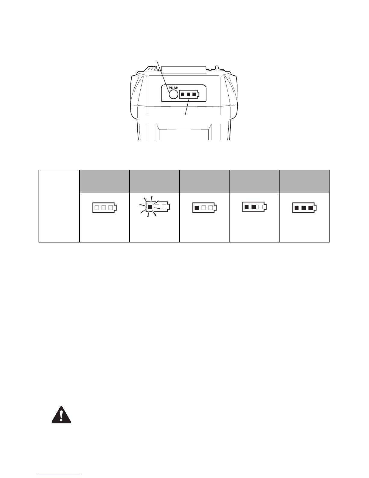
11.INSTRUCCIONES DE LA BATERÍA
Acerca del indicador de nivel de la batería
(1) Para comprobar el nivel de la batería (excepto mientras está cargando o funcionando
con la herramienta de carga), pulse el botón de comprobación del nivel de la batería.
(2) El indicador de nivel de la batería se ilumina según el nivel de la batería.
Vida útil del paquete de baterías
Si se observa alguna de las situaciones que se describen a continuación, el paquete de baterías está
en el final de su vida útil. Cámbielo por uno nuevo.
Aunque el paquete de baterías se ha cargado correctamente (plenamente cargado), se observa una
importante reducción del tiempo de amarre.
• Cuando esto suceda, no cargue el paquete de baterías. Si la velocidad de rotación del motor
se desacelera, se considera que la energía del paquete de baterías está a punto de agotarse.
El uso de la herramienta aumentará la descarga excesiva acortando la vida útil del paquete de
baterías y provocando problemas funcionales del cuerpo principal de la herramienta.
• No use un paquete de baterías caducado.
Si lo hace, el cuerpo principal del aparato sufrirá problemas funcionales. Cargar un paquete de
baterías caducado también provocará problemas funcionales en el cargador de baterías.
Reciclado de una batería de ion litio
El paquete de baterías de MAX utiliza una batería de ion litio; puede ser ilegal eliminar esta batería en
el sistema de residuos municipales. Consulte las disposiciones vigentes en su zona para el reciclado y
la eliminación correcta de este tipo de producto.
Cuando proceda a eliminar el paquete de baterías, asegúrese de poner la tapa en el terminal
(asegurada con cinta aislante) para evitar cortocircuitos.
Indicador de
nivel de la
batería
Nivel de la
batería:
0%
Nivel de la
batería:
aprox. 0 a 10%
Nivel de la
batería:
aprox. 10 a 40%
Nivel de la
batería:
aprox. 40 a 70%
Nivel de la
batería:
aprox. 70 a 100%
Todos los
indicadores
APAGADOS
Un indicador
rojo
intermitente
Un indicador
rojo
ENCENDIDO
Dos indicadores
rojos
ENCENDIDOS
Tres indicadores
rojos
ENCENDIDOS
Botón de comprobación de nivel de la batería
Indicador de nivel de la batería
AVISO
PRECAUCIÓN
Page 30

30
12. INSTRUCCIONES DE
FUNCIONAMIENTO
1. Cómo instalar el alambre de amarre
(Fig.6) Coloque el interruptor principal (e)
en la posición "OFF" ("DESCONECTADO"),
coloque el seguro del disparador (2) en la
posición "LOCK" ("BLOQUEADO") y extraiga
el paquete de baterías (5).
• Vigile que el alambre de amarre no se caiga
o reciba un golpe fuerte. Ello podría podría
provocar daños o averías en la
herramienta.
• Tenga cuidado con la punta del alambre
cuando manipule el alambre de amarre.
Podría provocarle lesiones.
1-1 (Fig.9) Presione el botón de desbloqueo (8)
de la herramienta y confirme que dicho
botón queda asegurado en el bloqueo (9).
1-2 (Fig.10) Tire de la punta del alambre de
amarre expuesto.
ASEGÚRESE DE USAR ÚNICAMENTE EL
ALAMBRE DE AMARRE ESPECIFICADO
(SERIE TW1061T de MAX).
El uso de un alambre de amarre que no sea el
especificado puede provocar averías en la
herramienta. Por lo tanto, asegúrese de usar
únicamente la serie TW1061T de MAX
especificada.
La RB441T no es compatible con la serie TW898
ni con la serie TW1525.
NO UTILICE ALAMBRE OXIDADO.
El uso de alambre oxidado puede provocar
problemas de funcionamiento en la herramienta.
1-3 (Fig.11) Gire el bloqueador del compartimento
de bobina (
6
) 45° hacia la izquierda.
1-4 (Fig.12, 13) Abra la cubierta del
compartimento de bobina (n) e instale el
alambre de amarre en el compartimento (7)
de modo que el lado de la ranura de sujeción
(o) de la bobina quede orientado hacia
arriba.
1-5 (Fig.14) Agarre la herramienta con la mano
izquierda, sujete la punta del alambre con la
mano derecha, y extraiga el alambre por la
ranura de sujeción.
Las dos puntas de alambre del nuevo alambre
de amarre están trenzadas.
1-6 (Fig.15) Estire la punta del alambre e
introduzca el alambre trenzado a lo largo de
la guía del alambre (i).
1-7 (Fig.16) Confirme a través de la ventanilla
que la parte trenzada del alambre ha pasado
por los dos engranajes de alimentación (h).
1-8 (Fig.17) Presione el bloqueo (9) hacia
arriba y confirme que el botón de
desbloqueo se ha elevado.
1-9 (Fig.18) Cierre la cubierta del compartimento
de bobina y gire el bloqueador del
compartimento 45° hacia la derecha.
Si la ventanilla está sucia
Abra la ventanilla (Fig.1.g) y elimine la
suciedad del interior de la ventanilla con un
paño. Después de limpiar, cierre de nuevo la
ventanilla para asegurarse de que ningún
material extraño penetre en la herramienta.
2. Cómo utilizar la RB441T
(Fig.6) Coloque el interruptor principal (e)
en la posición "OFF" ("DESCONECTADO"),
coloque el seguro del disparador (2) en la
posición "LOCK" ("BLOQUEADO") y extraiga
el paquete de baterías (5).
2-1 (Fig.19) Introduzca el paquete de baterías
en el cuerpo principal de la herramienta
hasta oír un clic.
2-2 (Fig.20) Cuando el interruptor principal (e)
está en posición "ON" ("CONECTADO"), el
gancho (Fig.1.f) de la punta gira
automáticamente para inicializarse. No
acerque los dedos a ninguna pieza giratoria
o móvil bajo ninguna circunstancia. Coloque
el interruptor principal en la posición "ON"
("CONECTADO") y el seguro del disparador
(2) en la posición "UNLOCK"
("DESBLOQUEADO").
2-3 (Fig.21) Incline la herramienta en un ángulo
de 45° respecto de las armaduras
entrecruzadas.
2-4 (Fig.22) Alinee la marca central (a) con el
centro de las armaduras entrecruzadas.
2-5 Cuando se acciona el disparador, la
herramienta completa automáticamente una
serie de acciones de amarre (alimentación,
corte, sujeción y amarre).
PRECAUCIÓN
AVISO
Page 31

31
• (Fig.23) Cuando el interruptor principal
(Fig.1.e) está en posición "ON"
("CONECTADO"), el gancho (Fig.1.f) de la
punta gira automáticamente para
inicializarse. No acerque los dedos a
ninguna pieza giratoria o móvil bajo
ninguna circunstancia.
• No toque ninguna pieza giratoria o móvil,
como el gancho de la punta o el alambre de
amarre, durante el trabajo de amarre
(mientras la herramienta está en
funcionamiento).
3. Cómo extraer el alambre de amarre
(Fig.6) Coloque el interruptor principal (e)
en la posición "OFF" ("DESCONECTADO"),
coloque el seguro del disparador (2) en la
posición "LOCK" ("BLOQUEADO") y extraiga
el paquete de baterías (5).
3-1 (Fig.9) Presione el botón de desbloqueo (8)
de la herramienta y confirme que dicho
botón queda asegurado en el bloqueo (9).
3-2 (Fig.11) Gire el bloqueador del
compartimento de bobina (6) para abrir la
cubierta del compartimento.
3-3 (Fig.24) Extraiga el alambre de amarre del
compartimento de bobina.
3-4 (Fig.25) Extraiga el alambre con la pieza de
plástico de la guía del alambre.
4. Cuando el alambre de amarre se
agota
(Fig.26) La pieza de plástico se desprende
cuando el alambre se agota, y puede
desecharse por separado como plástico y
alambre metálico (quedan unos 8" (20 cm) tras
un uso normal).
(Fig.6) Coloque el interruptor principal (e) en la
posición "OFF" ("DESCONECTADO"), coloque
el seguro del disparador (2) en la posición
"LOCK" ("BLOQUEADO") y extraiga el paquete
de baterías (5).
5. Ajuste de la tensión
(Fig.27.c) El disco selector le permite ajustar
ligeramente el par de tensión del alambre. Para
aumentar la tensión, gírelo hacia la izquierda.
Para disminuir la tensión, gírelo hacia la derecha.
6. Función de desconexión
automática
Esta herramienta tiene una función de
"Desconexión automática" que ahorra
consumo de energía de la batería cuando la
herramienta no está en funcionamiento.
Si la herramienta está sin funcionar durante 30
minutos, se desconecta automáticamente.
Cuando el suministro eléctrico se interrumpa
automáticamente, coloque el interruptor
principal en la posición "OFF"
("DESCONECTADO") y luego vuelva a colocarlo
en la posición "ON" ("CONECTADO") para
poner en funcionamiento la herramienta.
7. Para una tensión correcta
7-1 (Fig.21) Incline la herramienta en un ángulo
de 45° respecto de las armaduras
entrecruzadas.
7-2 (Fig.22) Alinee la marca central (a) con el
centro de las armaduras entrecruzadas.
7-3 (Fig.28) Coloque la herramienta
perpendicularmente a la superficie de las
armaduras entrecruzadas.
Durante el funcionamiento de la herramienta
No mueva la herramienta durante la operación
de amarre hasta que deje de funcionar
automáticamente.
7-4 (Fig.29) Amarre en dirección alterna.
7-5 (Fig.30) Amarre entrecruzado.
Antes de realizar el segundo amarre, doble
el nudo del primero.
8. Cómo instalar de nuevo un
alambre de amarre previamente
usado
(Fig.31) Introduzca los dos alambres en la guía
del alambre (i) sin trenzarlos.
9. (Fig.32) Cómo colocar y extraer el
gancho para cinturón de la
herramienta
El gancho para cinturón puede colocarse tanto
en el lado derecho como en el izquierdo de la
herramienta.
Montaje/Desmontaje del gancho para cinturón
(Montaje)
Inserte el gancho para cinturón en la ranura de
la herramienta. Fíjelo con un tornillo.
ADVERTENCIA
Page 32

32
(Desmontaje)
Afloje el tornillo y, a continuación, desmonte el
gancho para cinturón.
• Cuando utilice el gancho para cinturón o
cambie la posición, coloque el interruptor
principal (e) en la posición "OFF"
("DESCONECTADO"), coloque el seguro
del disparador (2) en la posición "LOCK"
("BLOQUEADO") y extraiga el paquete de
baterías (5).
De no observar esta instrucción, la
herramienta podría ponerse en marcha
accidentalmente y provocar un accidente.
• Antes de usar el gancho para cinturón,
asegúrese de que el gancho está
correctamente montado en la herramienta.
El uso de un gancho para cinturón montado
incorrectamente podría provocar lesiones
personales.
• Apriete firmemente el tornillo original
especificado.
Si el tornillo se afloja a causa de la vibración o
de otros movimientos generados durante el
funcionamiento, el tornillo flojo puede provocar
una caída accidental de la herramienta.
• Cuando utilice el gancho para cinturón, la
herramienta debe engancharse de forma
segura para que no se caiga.
Si la herramienta se cae, podría provocar un
accidente.
13.ALMACENAMIENTO
No guarde la herramienta en lugares fríos.
Manténgala en un lugar templado.
Cuando no la utilice, guarde la herramienta en
un lugar templado y seco. Manténgala fuera del
alcance de los niños.
EXTRAIGA LA BOBINA DE ALAMBRE DE
AMARRE
Al finalizar la operación de amarre con alambre,
extraiga la bobina de la herramienta.
GUARDE LA HERRAMIENTA
Cuando haya finalizado la operación de amarre o
cuando la herramienta no vaya a usarse durante
un tiempo, coloque el interruptor principal
(Fig.1.
e
) en la posición "OFF"
("DESCONECTADO"), coloque el seguro del
disparador (Fig.1.
2
) en la posición "LOCK"
("BLOQUEADO") y extraiga el paquete de
baterías (Fig.1.
5
). La herramienta y los
accesorios deben guardarse en un lugar seco y
bien ventilado en el que la temperatura no supere
los 104°F (40°C).
El paquete de baterías, con la tapa (Fig.2.
k
)
instalada para evitar cortocircuitos, debe
guardarse en un lugar seco y bien ventilado en el
que la temperatura no supere los 86°F (30°C).
ADVERTENCIA
Page 33

33
14.ALARMAS ACÚSTICAS Y PROCEDIMIENTOS A SEGUIR
Esta herramienta incorpora alarmas acústicas que suenan en las circunstancias siguientes. Si suena
una alarma acústica, lleve a cabo los procedimientos indicados a continuación.
<Tipos de alarmas acústicas y procedimientos a seguir>
• Si se producen las circunstancias siguientes, coloque el interruptor principal (Fig.1.e) en la
posición "OFF" ("DESCONECTADO"), coloque el seguro del disparador (Fig.1.
2
) en la
posición "LOCK" ("BLOQUEADO") y extraiga el paquete de baterías (Fig.1.
5
) antes de llevar
a cabo los procedimientos indicados.
• Cuando coloque el interruptor principal en la posición "ON", no toque las piezas de amarre
o giratorias bajo ninguna circunstancia.
Tipos de alarmas
acústicas
Causa posible Procedimientos a seguir
Una vez (pi, pi, pi...)
El alambre está atascado en el
gancho (Fig.1.f)
Compruebe si el alambre u otro objeto
se ha atascado en el gancho.
El motor está caliente
Deje que la herramienta descanse y se
enfríe.
Dos veces (pipi, pipi,
pipi...)
Queda poca carga en la batería Cargue el paquete de baterías.
El paquete de baterías no está
bien insertado.
Inserte correctamente el paquete de
baterías.
Tres veces
(pipipi, pipipi, pipipi...)
El alambre de amarre se ha
agotado
Cámbielo por uno nuevo.
El alambre de amarre se ha
atascado
Abra la cubierta del compartimento de
bobina (Fig.12.n) y libere el alambre
atascado.
Pitido agudo continuo
(piii...)
La guía de curvado (Fig.1.0) está
abierta
Confirme los diámetros compatibles de
las armaduras de refuerzo.
Un solo sonido corto y
continuo en tonos
graves y agudos
(pipo / pii poh pii poh...)
Estructura interna, defecto en el
mecanismo de accionamiento
interno
Interrumpa el funcionamiento
inmediatamente, coloque el interruptor
principal (Fig.6.e) en la posición "OFF"
("DESCONECTADO"), coloque el
seguro del disparador (Fig.6.2) en la
posición "LOCK" ("BLOQUEADO") y
extraiga el paquete de baterías
(Fig.6.5) antes de consultar el
problema. A continuación, póngase en
contacto con el proveedor al que
adquirió la herramienta o con un
distribuidor autorizado por MAX CO.,
LTD.
ADVERTENCIA
Page 34

34
<Si no suena ninguna alarma acústica pero el funcionamiento parece ser incorrecto>
Síntoma Causa posible Procedimientos a seguir
El interruptor principal
está en la posición "ON"
("CONECTADO") pero la
herramienta no funciona
La carga de la batería se ha
agotado
Instale una nueva batería y confirme
que la herramienta funciona.
El producto no funciona
La función de desconexión
automática está activada
Cambie el interruptor principal
(Fig.1.e) de la posición "OFF"
("DESCONECTADO") a la posición
"ON" ("CONECTADO").
El amarre no es correcto
El alambre toca las armaduras de
refuerzo durante el amarre
Realice la operación de amarre de
forma que el alambre no toque las
armaduras de refuerzo.
El alambre se retuerce
El tamaño de las armaduras de
refuerzo no es adecuado
Utilice armaduras de refuerzo con
diámetros compatibles.
El disco selector del par de tensión
se ha ajustado en un valor
demasiado alto
Ajuste el disco selector del par de
tensión (Fig.1.c) en un valor más bajo.
La tensión es demasiado
baja
El punto de amarre no está
situado en la marca central
(Fig.22.a)
Alinee la marca central con el centro de
las armaduras entrecruzadas y accione
el disparador.
El tamaño de las armaduras de
refuerzo no es adecuado
Utilice armaduras de refuerzo con
diámetros compatibles.
El disco selector del par de tensión
se ha ajustado en un valor
demasiado bajo
Ajuste el disco selector del par de
tensión (Fig.1.c) en un valor más alto.
La forma del amarre está
visiblemente deformada
Hay piezas desgastadas o
deterioradas
Interrumpa el funcionamiento
inmediatamente, coloque el interruptor
principal (Fig.6.e) en la posición "OFF"
("DESCONECTADO"), coloque el
seguro del disparador (Fig.6.2) en la
posición "LOCK" ("BLOQUEADO") y
extraiga el paquete de baterías
(Fig.6.5) antes de consultar el
problema. A continuación, póngase en
contacto con el proveedor al que
adquirió la herramienta o con un
distribuidor autorizado por MAX CO.,
LTD.
La herramienta se atasca
con mayor frecuencia
Page 35

35
SOMMAIRE
1. NOM DES PIÈCES...................................................................... 36
2. LISTE DU CONTENU ................................................................. 36
3. AVERTISSEMENTS DE SÉCURITÉ GÉNÉRAUX RELATIFS
AUX OUTILS ÉLECTRIQUES .................................................... 37
4. DISPOSITIFS DE SÉCURITÉ RB441T....................................... 39
5. CARACTÉRISTIQUES TECHNIQUES ET DONNÉES
TECHNIQUES DE L'OUTIL ........................................................ 42
6. CARACTÉRISTIQUES TECHNIQUES ....................................... 43
7. ANNÉE DE PRODUCTION......................................................... 43
8. SPÉCIFICATIONS DU FIL.......................................................... 44
9. APPLICATIONS.......................................................................... 44
10. TAILLES DE BARRES UTILISABLES....................................... 44
11. INSTRUCTIONS CONCERNANT LA BATTERIE ...................... 45
12. UTILISATION .............................................................................. 46
13. ENTREPOSAGE ......................................................................... 48
14. SONNERIES D'AVERTISSEMENT ET PROCÉDURES À
SUIVRE ....................................................................................... 49
DÉFINITION DES MOTS-INDICATEURS
AVERTISSEMENT : indique une situation dangereuse qui, si elle n'est pas évitée, pourrait entraîner la
mort ou des blessures graves.
ATTENTION : indique une situation dangereuse qui, si elle n'est pas évitée, pourrait entraîner des
blessures graves mineures ou modérées.
AVIS : indique un message relatif à des dommages matériels
FRANÇAIS
MODE D'EMPLOI ET CONSIGNES DE SÉCURITÉ
Traduction des
instructions originales
Page 36

36
1. NOM DES PIÈCES
Fig. 1
Fig. 2
Fig. 3
Reportez-vous au manuel d'utilisation et d'entretien du JC925
Fig. 12
Fig. 13
2. LISTE DU CONTENU
• Outil de ligature de barres MAX / RB441T
• Bloc batterie lithium-ion/JPL91440A
• Chargeur de batterie lithium-ion/JC925
• Cordon d'alimentation
• MODE D'EMPLOI ET CONSIGNES DE SÉCURITÉ (le présent manuel)
1 Bras
2 Verrouillage du
déclencheur
3 Déclencheur
4 Poignée
5 Bloc batterie
6 Butée du magasin
7 Magasin
8 Bouton de désengagement
9 Verrou de levier
0 Guide de bouclage
a Repère central
b Numéro de série
c Molette de couple
d Voyant LED
e Interrupteur principal
f Crochet
g Fenêtre
h Engrenage d'alimentation
i Guide fil
j Crochet de ceinture
k Couvercle de batterie
l Contact
m Verrou
n Capot du magasin
o Fente de maintien
Page 37

37
3. AVERTISSEMENTS DE
SÉCURITÉ GÉNÉRAUX
RELATIFS AUX OUTILS
ÉLECTRIQUES
1. SÉCURITÉ DE LA ZONE DE TRAVAIL
• Maintenez la zone de travail propre et
bien éclairée. Des zones en désordre ou
sombres entraînent des accidents.
• N'utilisez pas les outils électriques
dans des atmosphères explosives,
telles qu'en présence de liquides, gaz
ou poussière inflammables. Les outils
électriques créent des étincelles qui
enflamment la poussière ou les vapeurs.
• Tenez les enfants ou les personnes qui
vous entourent à distance lorsque
vous utilisez un outil électrique. Des
distractions peuvent vous faire perdre le
contrôle de l'outil.
2. SÉCURITÉ ÉLECTRIQUE
• Les fiches des outils électriques
doivent s'adapter à la prise. Ne
modifiez jamais en aucune manière la
fiche d'un outil. N'utilisez aucune fiche
d'adaptateur avec des outils
électriques mis à la terre (masse). Des
fiches non modifiées et des prises
adaptées réduiront le risque de choc
électrique.
• Évitez tout contact corporel avec les
surfaces mises à la terre ou à la masse,
telles que des tuyaux, des radiateurs,
des cuisinières et des réfrigérateurs.
Le risque de choc électrique est accru si
votre corps est mis à la terre ou à la
masse.
• N'exposez pas les outils électriques à
la pluie ou l'humidité. La pénétration
d'eau dans un outil électrique augmente
le risque de choc électrique.
• Ne détériorez pas le cordon. N'utilisez
jamais le cordon pour porter, tirer ou
débrancher l'outil électrique.
Maintenez le cordon à distance de la
chaleur, de l'huile, de bords tranchants
et de pièces mobiles. Des cordons
endommagés ou emmêlés augmentent le
risque de choc électrique.
•
Lorsque vous utilisez un outil
électrique à l'extérieur, utilisez une
rallonge adaptée.
L'utilisation d'une
rallonge adaptée à une utilisation à
l'extérieur réduit le risque de choc
électrique.
• Si vous êtes obligé d'utiliser un outil
électrique dans un endroit humide,
utilisez une alimentation électrique
protégée par un disjoncteur
différentiel de fuite à la terre (DDFT).
L'utilisation d'un DDFT réduit le risque de
choc électrique.
3. SÉCURITÉ PERSONNELLE
•
Restez vigilant, regardez ce que vous
faites et faites preuve de bon sens
lorsque vous utilisez un outil électrique.
N'utilisez pas un outil électrique lorsque
vous êtes fatigué ou sous l'influence de
drogues, d'alcool ou de médicaments.
Un moment d'inattention lorsque vous
utilisez des outils électriques peut entraîner
des blessures graves.
• Utilisez un équipement de protection
individuel. Portez toujours une
protection oculaire. Un équipement de
protection tel qu'un masque
antipoussière, des chaussures de
sécurité antidérapantes, un casque ou
une protection auditive, utilisé dans des
conditions appropriées réduira les
dommages corporels.
• Évitez tout démarrage involontaire.
Vérifiez que l'interrupteur est en
position Arrêt avant de brancher la
source électrique et/ou le bloc batterie,
de ramasser ou de transporter l'outil.
Le transport d'outils électriques avec le
doigt sur l'interrupteur ou la mise sous
tension d'outils électriques dont
l'interrupteur est en position Marche
entraîne des risques d'accident.
LISEZ TOUS LES AVERTISSEMENTS DE
SÉCURITÉ ET TOUTES LES CONSIGNES.
Un non-respect de ces avertissements et
consignes peut entraîner un choc électrique,
un incendie et/ou des blessures graves.
Conservez tous les avertissements et
consignes pour une consultation
ultérieure. Le terme « outil électrique » dans
les avertissements fait référence à votre outil
électrique raccordé au secteur (cordon
d'alimentation) ou fonctionnant avec une
batterie (sans fil).
AVERTISSEMENT
Page 38

38
• Retirez toute clé ou clavette de calage
avant de mettre l'appareil électrique
sous tension.
Une clé ou une clavette toujours fixée sur
une pièce rotative de l'outil électrique peut
entraîner des dommages corporels.
• Ne tendez pas le bras trop loin. Restez
bien en équilibre sur vos pieds en
permanence. Ceci permet un meilleur
contrôle de l'outil électrique dans des
situations inattendues.
• Portez une tenue appropriée. Ne
portez pas de vêtements amples ni de
bijoux. Tenez vos cheveux, vêtements
et gants à distance des pièces
mobiles. Des vêtements amples, des
bijoux ou des cheveux longs peuvent se
coincer dans les pièces mobiles.
• Si des appareils sont fournis pour le
raccordement aux dispositifs de
récupération et d'extraction de la
poussière, vérifiez qu'ils sont
raccordés et correctement utilisés.
L'utilisation d'un dispositif de récupération
de la poussière peut réduire les risques
liés à la poussière.
4. UTILISATION ET ENTRETIEN D'UN OUTIL
ÉLECTRIQUE
• N'exercez aucune force sur l'outil.
Utilisez l'outil électrique adapté à votre
application. L'outil électrique adapté
exécutera le travail d'une manière plus
correcte et plus sûre à la vitesse pour
laquelle il est conçu.
• N'utilisez pas l'outil électrique si
l'interrupteur ne fonctionne pas
correctement. Un outil électrique qui ne
peut pas être commandé à l'aide de
l'interrupteur est dangereux et doit être
réparé.
• Débranchez la fiche de l'alimentation
électrique et/ou le bloc batterie de
l'outil électrique avant d'effectuer un
quelconque réglage, de changer
d'accessoire ou de ranger l'outil
électrique. Ces mesures préventives
réduisent le risque d'un démarrage
accidentel de l'outil électrique.
• Rangez des outils électriques à l'arrêt
hors de portée des enfants et ne
laissez pas des personnes non
familiarisées avec l'outil électrique ou
ces consignes utiliser cet outil. Les
outils électriques sont dangereux dans
les mains d'utilisateurs non formés.
• Entretenez les outils électriques.
Vérifiez que des pièces mobiles ne
sont pas désalignées ou coincées, que
des pièces ne sont pas cassées ou
vérifiez tout autre état qui pourrait
gêner le fonctionnement de l'outil
électrique. Si l'outil électrique est
endommagé, faites-le réparer. Un
grand nombre d'accidents sont causés
par des outils électriques mal entretenus.
• Maintenez les outils de coupe affûtés
et propres. Des outils de coupe
correctement entretenus avec des bords
tranchants affûtés risquent moins de se
coincer et sont plus faciles à contrôler.
• Utilisez l'outil électrique, les
accessoires et les embouts, etc.
conformément à ces consignes, en
prenant en compte les conditions de
travail et le travail à réaliser. L'utilisation
de l'outil électrique pour des opérations
différentes de celles pour lesquelles il est
prévu peut entraîner une situation
dangereuse.
5. UTILISATION ET ENTRETIEN D'UN OUTIL
FONCTIONNANT AVEC UNE BATTERIE
• Rechargez uniquement à l'aide du
chargeur spécifié par le fabricant. Un
chargeur adapté à un type de bloc
batterie peut entraîner un risque
d'incendie lorsqu'il est utilisé avec un
autre bloc batterie.
• Utilisez les outils électriques
uniquement avec les blocs batteries
spécifiés. L'utilisation d'autres blocs
batteries peut entraîner un risque de
blessure et d'incendie.
• Lorsque le bloc batterie n'est pas
utilisé, tenez-le à distance d'autres
objets métalliques, tels que des
trombones, pièces, clés, clous, vis ou
autres petits objets métalliques, qui
peuvent créer un contact entre les
deux bornes. Un court-circuit des bornes
de la batterie peut entraîner des brûlures
ou un incendie.
• En cas d'utilisation incorrecte, du
liquide peut être éjecté de la batterie ;
évitez tout contact avec ce liquide. En
cas de contact accidentel, rincez avec
de l'eau. Si du liquide entre en contact
avec les yeux, consultez
immédiatement un médecin. Le liquide
éjecté de la batterie peut entraîner une
irritation ou des brûlures.
Page 39

39
6. RÉPARATION
•
Faites réparer votre outil électrique par
un réparateur qualifié qui n'utilise que
des pièces de rechange d'origine.
Ceci
garantit le maintien de la sécurité de l'outil
électrique.
• N'utilisez pas l'outil électrique sous la
pluie, près de projections d'eau, dans un
endroit mouillé ou humide. L'utilisation de
l'outil dans ces conditions ou des conditions
similaires augmente le risque de choc
électrique, de dysfonctionnement dangereux
et de surchauffe.
• NE JETEZ PAS LES BLOCS BATTERIES/
BATTERIES AU FEU OU DANS L'EAU. Les
blocs batteries/batteries doivent être collectés,
recyclés ou mis au rebut d'une manière
respectueuse de l'environnement.
• PROTÉGEZ LA BATTERIE CONTRE LA
CHALEUR, L'EXPOSITION AU SOLEIL. Il
existe un risque d'explosion.
• CHARGEZ LE BLOC BATTERIE DANS UNE
TEMPÉRATURE AMBIANTE COMPRISE
ENTRE 41 °F (5 °C) ET 104 °F (40 °C).
• Le produit que vous avez acheté est
alimenté par une batterie Li-ion recyclable.
À la fin de sa durée de vie utile, dans
plusieurs États et conformément à
plusieurs lois, il est illégal de mettre cette
batterie au rebut dans les déchets
municipaux. Appelez le 1-800-8-BATTERY
pour plus d'informations sur la manière de
recycler cette batterie.
4. DISPOSITIFS DE
SÉCURITÉ RB441T
1. INSPECTEZ LES PIÈCES AVANT LA MISE
EN PLACE DU BLOC BATTERIE
• Examinez les vis, afin de vérifier leur
serrage.
En cas de mauvais serrage, vous risquez
un accident ou une cassure. Si vous
constatez une vis desserrée, resserrez-la
complètement.
• Examinez l'outil, à la recherche de pièces
détériorées.
Les pièces s'usent au fil de l'utilisation.
Recherchez également des pièces
manquantes, défectueuses ou dégradées.
Si vous devez remplacer ou réparer une
pièce, procurez-vous la pièce de rechange
chez le distributeur où vous avez acheté
l'outil ou auprès de distributeurs agréés
MAX CO., LTD.
Utilisez uniquement des pièces de
rechange d'origine.
2. RÉGLEZ L'INTERRUPTEUR PRINCIPAL
(Fig. 6.e) SUR « OFF », LE
VERROUILLAGE DU DÉCLENCHEUR
(Fig. 6.2) SUR « LOCK » ET ÔTEZ LE
BLOC BATTERIE (Fig. 6.5), LORSQUE
VOUS CHANGEZ LE BLOC BATTERIE,
QUE VOUS REMPLACEZ OU RÉGLEZ LE
FIL À LIGATURE, EN CAS D'ANOMALIE
OU LORSQUE VOUS N'UTILISEZ PAS
L'OUTIL.
Si vous laissez l'outil sous tension dans ces
conditions, vous risquez de provoquer une
panne ou de l'endommager.
3. GARDEZ EN PERMANENCE LES DOIGTS
ET AUTRES PARTIES DU CORPS
ÉLOIGNÉS DE LA PARTIE ENTRE LE
BRAS ET LE GUIDE DE BOUCLAGE
(Fig. 23).
Tout manquement à cette consigne peut
entraîner des blessures graves.
4. GARDEZ LES DOIGTS ET AUTRES
PARTIES DU CORPS ÉLOIGNÉS DU FIL À
LIGATURE PENDANT L'UTILISATION.
Tout manquement à cette consigne peut
entraîner des blessures graves.
Page 40

40
5. NE DIRIGEZ PAS L'OUTIL VERS UNE
PERSONNE.
Vous risquez de blesser une personne
travaillant à proximité, si l'outil la touche. Au
cours de l'utilisation, soyez très attentif à ne
pas approcher les mains, les jambes ou
toute autre partie du corps, du bras de l'outil.
6. NE PAS GARDER LE DOIGT SUR LE
DÉCLENCHEUR EN DEHORS DE
L'UTILISATION
Tout manquement à cette consigne peut
provoquer une ligature accidentelle,
entraînant des blessures graves.
7. NE PAS UTILISER L'OUTIL DANS DES
CONDITIONS ANORMALES
Si l'outil n'est pas en état correct de
fonctionnement, ou si vous remarquez une
condition anormale, mettez-le
immédiatement hors tension (interrupteur
principal sur « OFF »), verrouillez le
déclencheur et faites-le examiner pour
réparation.
8. UNE FOIS LA BATTERIE EN PLACE, SI
L'OUTIL SE MET EN MARCHE SANS
APPUYER SUR LE DÉCLENCHEUR OU SI
L'OPÉRATEUR REMARQUE UN
ÉCHAUFFEMENT, UNE ODEUR OU UN
BRUIT INHABITUEL, ARRÊTEZ-LE.
Tout manquement à cette consigne peut
entraîner des blessures graves. Renvoyez
l'outil au distributeur pour une inspection de
sécurité.
9. NE PAS MODIFIER L'OUTIL.
Toute modification de l'outil a une incidence
sur ses performances et sa sécurité. D'autre
part, toute modification peut provoquer des
blessures graves et annule la garantie.
10. MAINTENIR L'OUTIL EN BON ÉTAT DE
FONCTIONNEMENT
Pour préserver le fonctionnement optimal et
la sécurité de l'outil, faites-le réparer en cas
d'usure ou de détérioration. Maintenez la
poignée sèche et propre, exempte tout
particulièrement d'huile et de graisse.
11. UTILISER UNIQUEMENT LE BLOC
BATTERIE RECOMMANDÉ
Si l'outil est branché sur une alimentation
autre que le bloc batterie recommandé, telle
qu'une batterie rechargeable, une batterie à
anode sèche ou une batterie
d'accumulateurs utilisée dans l'industrie
automobile, il risque d'être endommagé, de
tomber en panne, de chauffer, voire même
de prendre feu. Ne branchez en aucun cas
l'outil sur une alimentation autre que le bloc
batterie recommandé.
12. POUR UN MEILLEUR
FONCTIONNEMENT, CHARGER
COMPLÈTEMENT LA BATTERIE AVANT
UTILISATION
Un nouveau bloc batterie, ou un non utilisé
pendant une période prolongée, peut être
partiellement déchargé et nécessiter une
charge. Avant d'utiliser l'outil, rechargez le
bloc batterie à l'aide du chargeur MAX
indiqué.
13. PRÉCAUTION POUR LA CHARGE DE LA
BATTERIE
13-1 Utilisez uniquement le chargeur MAX
avec le bloc batterie MAX.
Tout manquement à cette consigne
peut provoquer une surchauffe/un
incendie de la batterie, entraînant de
graves blessures.
13-2 Chargez la batterie à partir d'une
prise secteur de 120 V CA.
Tout manquement à cette consigne
peut provoquer une surchauffe, ou une
charge incorrecte susceptible
d'entraîner des blessures graves.
13-3 N'utilisez jamais de transformateur.
13-4 Ne branchez pas le chargeur sur un
alternateur de moteur produisant du
courant continu.
Le chargeur tomberait en panne ou
serait endommagé par la surchauffe.
13-5 Évitez de charger la batterie sous la
pluie, dans un endroit humide, ou
soumis à des éclaboussures d'eau.
Le fait de charger la batterie dans ces
conditions risquerait de provoquer un
choc électrique ou un court-circuit
entraînant une détérioration liée à la
surchauffe, avec risque d'incendie de
l'outil.
Page 41

41
13-6 Ne touchez pas le cordon
d'alimentation avec la main ou un
gant mouillé.
Vous risqueriez un choc électrique.
13-7 Ne placez pas de chiffon ni autre
obstruction sur le chargeur pendant
la charge de la batterie.
Cela provoquerait une surchauffe et
une détérioration consécutive, voire
même l'incendie de l'outil.
13-8 Conservez le bloc batterie et le
chargeur à l'abri des flammes et de la
chaleur.
13-9 Ne chargez pas le bloc batterie à
proximité de matières inflammables.
13-10 Chargez le bloc batterie dans un
endroit bien aéré.
Évitez de charger le bloc batterie sous
les rayons directs du soleil.
13-11 Chargez le bloc batterie dans une
température ambiante comprise
entre41 °F (5 °C) et 104 °F (40 °C).
13-12 Évitez d'utiliser le chargeur de
batterie de façon continue.
Laisser reposer le chargeur 15 minutes
entre deux utilisations pour éviter tout
problème de fonctionnement.
13-13 Tout objet obstruant les orifices de
ventilation ou le connecteur du bloc
batterie risque de provoquer un choc
électrique ou des anomalies de
fonctionnement.
Éliminez toute poussière ou objet
étranger du chargeur avant son
utilisation.
13-14 Manipulez le cordon d'alimentation
avec soin.
Ne transportez pas le chargeur par son
cordon d'alimentation. N'utilisez pas le
cordon d'alimentation pour le
débrancher de la prise murale ; vous
risquez de l'endommager, de rompre
les fils ou de provoquer un court-circuit.
Ne laissez pas le cordon d'alimentation
entrer en contact avec des outils à bord
tranchant, des matériaux chauds ou de
la graisse. Un cordon d'alimentation
endommagé doit être réparé ou
remplacé.
13-15 Ne chargez pas des batteries non
rechargeables au moyen de ce
chargeur.
13-16 Ce chargeur ne doit pas être utilisé
par des enfants ou des personnes
handicapées sans la surveillance
d'un responsable.
13-17 Les enfants doivent être surveillés
afin de s'assurer qu'ils ne jouent pas
avec le chargeur.
13-18 Placez un couvercle (Fig. 2.k) sur
les contacts (Fig. 2.l) du bloc
batterie.
Lorsque la batterie n'est pas utilisée,
placez un couvercle sur ses contacts de
façon à empêcher tout court-circuit.
13-19 Ne laissez pas les contacts
(métalliques) de la batterie entrer en
court-circuit.
Un court-circuit des contacts
entraînerait un fort courant provoquant
un échauffement et une détérioration
de la batterie.
13-20 Pendant l'été, ne laissez pas l'outil
dans un véhicule ou exposé aux
rayons directs du soleil. La forte
température risquerait
d'endommager le bloc batterie.
13-21 Ne stockez pas un bloc batterie
complètement déchargé. Un bloc
batterie retiré de l'outil pendant une
longue période risque de se
détériorer s'il est complètement
déchargé. Rechargez-le dès qu'il est
déchargé.
14. PORT DE GANTS DE PROTECTION
CONSEILLÉ PENDANT L'UTILISATION
La ligature a des bords coupants. Pour éviter
les blessures graves, ne touchez pas les
bords coupants.
15. AVANT TOUTE UTILISATION
(Fig. 4 et 5) Vérifiez que les dispositifs de
sécurité fonctionnent correctement. Dans le
cas contraire, évitez d'utiliser l'outil.
Page 42

42
5. CARACTÉRISTIQUES TECHNIQUES ET DONNÉES
TECHNIQUES DE L'OUTIL
<CHARGEUR DE BATTERIE>
<BLOC BATTERIE>
DESCRIPTION DU PRODUIT Outil de ligature de barres MAX « TWINTIER »
NUMÉRO DU PRODUIT RB441T
DIMENSIONS (bloc batterie compris) (H) 11-1/2" (295 mm) x (l) 4-7/8" (125 mm) x (L) 13" (330 mm)
POIDS (bloc batterie compris) 5,6 lbs (2,5 kg)
BATTERIE Bloc batterie lithium-ion/JPL91440A
TEMPÉRATURE DE
FONCTIONNEMENT
14 °F à 104 °F (-10 °C à 40 °C)
HUMIDITÉ 80 % d'humidité relative au maximum
DESCRIPTION DU PRODUIT Chargeur de batterie lithium-ion
NUMÉRO DU PRODUIT JC925
ENTRÉE 120 V CA 60 Hz 2,6 A 160 W
SORTIE 14,4 V CC 7,5 A, 18 V CC 5,4 A, 25,2 V CC 4,5 A
POIDS 3,3 lbs (1,5 kg)
PLAGE DE TEMPÉRATURES DE
FONCTIONNEMENT
41 °F à 104 °F (5 °C à 40 °C)
PLAGE D'HUMIDITÉ DE
FONCTIONNEMENT
80 % d'humidité relative au maximum
DESCRIPTION DU PRODUIT Bloc batterie lithium-ion
NUMÉRO DU PRODUIT JPL91440A
TENSION NOMINALE 14,4 V CC (3,6 V x 4 cellules)
CAPACITÉ NOMINALE 3,9 Ah (3 900 mAh)
TEMPS DE CHARGE Charge rapide – env. 33 min. (env. 90 % de la capacité)
Charge complète – env. 45 min. (100 % de la capacité)
ACCESSOIRES Couvercle de batterie
POIDS 1,1 lbs (0,5 kg)
TEMPÉRATURE DE CHARGE 41 °F à 104 °F (5 °C à 40 °C)
PLAGE DE TEMPÉRATURES DE
FONCTIONNEMENT
32 °F à 104 °F (0 °C à 40 °C)
PLAGE D'HUMIDITÉ DE
FONCTIONNEMENT
80 % d'humidité relative au maximum
Ligatures par charge Env. 4 000 ligatures (* dans les conditions suivantes : température
normale, batterie complètement chargée, non utilisée et barres
#4 x #4 (13mm x 13mm))
Page 43

43
6. CARACTÉRISTIQUES TECHNIQUES
6-1 BRUIT
Valeur mesurée conformément à la norme EN 60745 :
Niveau de pression acoustique pondérée A (LpA) : 79 dB
Incertitude (KpA) : 3 dB
Niveau de puissance acoustique pondérée A (LWA) : 79 dB
Incertitude (KWA) : 3 dB
6-2 VIBRATIONS
Valeur mesurée conformément à la norme EN 60745 :
Valeurs totales des vibrations (ah) : 0,5 m/s
2
Incertitude (K) : 0,1 m/s
2
• La valeur totale déclarée d'émission des vibrations a été mesurée conformément à une méthode standard de
test et elle peut être utilisée pour comparer un outil à un autre.
• La valeur totale déclarée d'émission des vibrations peut également être utilisée dans le cadre d'une évaluation
préliminaire de l'exposition.
• L'émission de vibrations pendant l'utilisation réelle de l'outil électrique peut être différente de la valeur d'émission
déclarée en fonction de la manière dont l'outil est utilisé.
• Veillez à identifier les mesures de sécurité visant à protéger l'utilisateur et basées sur une estimation de
l'exposition dans les conditions réelles d'utilisation (en prenant en compte toutes les parties du cycle d'utilisation,
notamment le nombre de fois où l'outil est mis hors tension et lorsqu'il fonctionne au ralenti en plus de la durée
d'utilisation du déclencheur).
6-3 ÉMISSION DE RAYONNEMENTS 30 - 1 000 MHZ Classe A
Ceci est un produit de classe A. Dans un environnement domestique, ce produit peut provoquer des interférences
radio et amener l'utilisateur à prendre des mesures appropriées.
6-4 Catégorie de surtension - Catégorie 1 en conformité avec la norme CEI 60664-1
6-5 Degré de pollution - Catégorie 4 en conformité avec la norme CEI 60664-1
6-6 Directives de conception – Directives de l'équipement, annexe 1, EN60745-1, EN60745-2-18
7. ANNÉE DE PRODUCTION
Ce produit comporte le numéro de fabrication sur le corps (Fig. 1.b). Les deux chiffres les plus à gauche
du numéro indiquent l’année de production.
AVERTISSEMENT
AVERTISSEMENT
(Exemple)
17526035D
Année 2017
Page 44
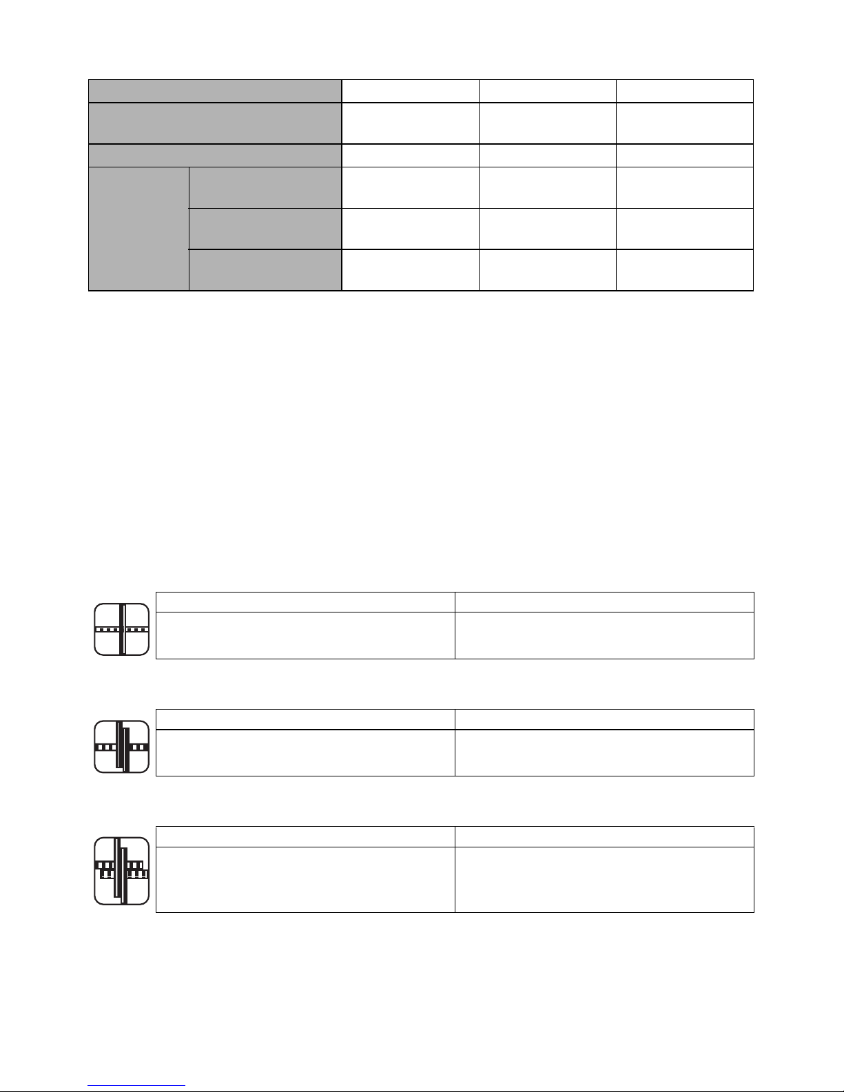
44
8. SPÉCIFICATIONS DU FIL
*RB441T n'est pas compatible avec les séries TW898 et TW1525.
9. APPLICATIONS
• Panneaux de béton préfabriqués
• Fondation de bâtiments
• Immeuble commercial
• Ponts et chaussées
• Canalisations de chauffage de sol
10.TAILLES DE BARRES UTILISABLES
■ Combinaison de 2 barres
■ Combinaison de 3 barres
■ Combinaison de 4 barres
FIL À LIGATURE TW1061T TW1061T-PC TW1061T-EG
TYPE DE FIL
Fil recuit
Fil à revêtement
multiple
Fil électrozingué
DIAMÈTRE 19GA (1,0 mm) 19GA (1,1 mm) 19GA (1,0 mm)
LIGATURES/
BOBINE
#3 × #3 (10 mm × 10 mm)
Env. 265
ligatures
Env. 230
ligatures
Env. 265
ligatures
#4 × #4 (13 mm × 13 mm)
Env. 240
ligatures
Env. 210
ligatures
Env. 240
ligatures
#7 × #5 × #5
(22 mm × 16 mm × 16 mm)
Env. 170
ligatures
Env. 150
ligatures
Env. 170
ligatures
Minimum Maximum
#3 × #3 (10 mm × 10 mm)
#7 × #7 (22 mm × 22 mm)
#8 × #6 (25 mm × 19 mm)
Minimum Maximum
#3 × #3 × #3 (10 mm × 10 mm × 10 mm)
#7 × #5 × #5 (22 mm × 16 mm × 16 mm)
#8 × #4 × #4 (25 mm × 13 mm × 13 mm)
Minimum Maximum
#3 × #3 × #3 × #3
(10 mm × 10 mm × 10 mm × 10 mm)
#5 × #5 × #4 × #4
(16 mm × 16 mm × 13 mm × 13 mm)
Page 45

45
11.INSTRUCTIONS CONCERNANT LA BATTERIE
Information sur l'indicateur du niveau de batterie
(1) Pour vérifier le niveau de batterie (en dehors de la période de charge ou d'utilisation
de l'outil de charge), appuyez sur le bouton de vérification du niveau de batterie.
(2) La jauge de niveau de batterie s'allume en fonction du niveau de batterie.
Durée de vie du bloc batterie
Si vous constatez l'une des conditions décrites ci-dessous, le bloc batterie est en fin de vie. Procédez à
son remplacement.
Bien que la batterie soit complètement chargée (100 % de la capacité), vous constatez une baisse
importante de sa puissance au niveau du temps de ligature.
•
Dans ces conditions, n'épuisez pas plus la batterie. En cas de ralentissement de la vitesse de
rotation du moteur, vous pouvez considérer la batterie comme presque épuisée. Si vous
continuez à utiliser l'outil, vous provoquez sa décharge complète et risquez non seulement de
réduire la longévité de la batterie, mais également de provoquer un dysfonctionnement de l'outil.
•
N'utilisez pas une batterie en fin de vie.
Vous risquez de provoquer un dysfonctionnement de l'outil. Le fait de recharger une batterie qui
est hors de service risque également de provoquer un mauvais fonctionnement du chargeur.
Recyclage des batteries Li-ion
Le bloc batterie MAX contient des batteries Li-ion qu'il est interdit de jeter avec les ordures ménagères.
Consultez votre organisme local de collecte des déchets pour connaître les possibilités de recyclage ou
de mise au rebut.
Lorsque vous mettez le bloc batterie au rebut, assurez-vous de placer le couvercle sur ses
contacts (en le fixant avec du ruban adhésif isolant) afin d'éviter un possible court-circuit.
Jauge du
niveau de
batterie
Niveau de
batterie :
0%
Niveau de
batterie :
entre 0 et 10 %
environ
Niveau de
batterie :
entre 10 et 40%
environ
Niveau de
batterie :
entre 40 et 70%
environ
Niveau de
batterie :
entre 70 et 100%
environ
Tous les
témoins sont
éteints
Un indicateur
rouge clignote
Un indicateur
rouge allumé
Deux
indicateurs
rouges allumés
Trois
indicateurs
rouges allumés
Bouton de vérification du niveau de batterie
Jauge du niveau de batterie
AVIS
ATTENTION
Page 46

46
12. UTILISATION
1. Méthode de réglage du fil à
ligature
(Fig. 6) Réglez l'interrupteur principal (e) sur
« OFF », le déclencheur (2) sur « LOCK » et
ôtez le bloc batterie (5).
• Veillez à ne pas laisser tomber le fil à
ligature ni à lui faire subir d'impact violent.
Cela pourrait endommager l'outil et
provoquer un dysfonctionnement.
• Faites attention à l'extrémité du fil lorsque
vous ramassez le fil à ligature Vous
pourriez vous blesser.
1-1 (Fig. 9) Appuyez sur le bouton de
désengagement (8) de l'outil et vérifiez qu'il
est maintenu par le verrou du levier (9).
1-2 (Fig. 10) Étirez l'extrémité du fil à ligature
enroulé.
ASSUREZ-VOUS D'UTILISER UNIQUEMENT
LE FIL À LIGATURE RECOMMANDÉ (série
MAX TW1061T).
L'utilisation d'un fil autre que celui spécifié risque
de provoquer la panne de l'outil. Par
conséquent, veillez à n'utiliser que la série
spécifiée MAX TW1061T.
Le RB441T n'est pas compatible avec les séries
TW898 et TW1525.
N'UTILISEZ PAS DE FIL ROUILLÉ
L'utilisation d'un fils rouillé pourrait provoquer
des anomalies de fonctionnement de l'outil.
1-3 (Fig. 11) Faites pivoter la butée du magasin
(6) de 45° dans le sens inverse des
aiguilles d'une montre.
1-4 (Fig. 12,13) Ouvrez le capot du magasin (n)
et mettez en place le fil à ligature dans le
magasin (7) tout en orientant vers le haut le
côté de la fente de maintien (o) de la
bobine.
1-5 (Fig. 14) Saisissez l'outil de la main gauche
et tenez l'extrémité du fil de la main droite,
puis ôtez le fil de la fente de maintien.
Les 2 extrémités d'un nouveau fil à ligature
sont torsadées.
1-6 (Fig. 15) Redressez l'extrémité du fil et
insérez le fil torsadé dans le guide file (i)
parallèle.
1-7 (Fig. 16) Vérifiez par la fenêtre que la partie
torsadée du fils a dépassé les deux
engrenages d'alimentation (h).
1-8 (Fig. 17) Appuyez sur le verrou du levier (9)
vers le haut et vérifiez que le bouton de
désengagement est relevé.
1-9 (Fig. 18) Fermez le capot du magasin et
tourner la butée du magasin de 45° dans le
sens des aiguilles d'une montre.
Si la fenêtre est sale
Ouvrez la fenêtre (Fig. 1.g) et essuyez la saleté
à l'intérieur de celle-ci à l'aide d'un chiffon.
Fermez à nouveau la fenêtre après l'avoir
nettoyée en vous assurant qu'aucun corps
étranger ne peut pénétrer à l'intérieur de l'outil.
2. Méthode d'utilisation du RB441T
(Fig. 6) Réglez l'interrupteur principal (e) sur
« OFF », le déclencheur (2) sur « LOCK » et
ôtez le bloc batterie (5).
2-1 (Fig. 19) Insérez le bloc batterie sur l'outil
jusqu'à ce que vous entendiez un déclic.
2-2 (Fig. 20) Lorsque l'interrupteur principal (e)
est sur « ON », le crochet (Fig. 1.f) de
l'extrémité pivote automatiquement pour
l'initialisation ; n'approchez en aucun cas les
doigts des parties tournantes et mobiles.
Réglez l'interrupteur principal sur « ON » et le
verrou du déclencheur (2) sur « UNLOCK ».
2-3 (Fig. 21) Inclinez l'outil à 45° par rapport à
l'intersection des barres.
2-4 (Fig. 22) Alignez le repère central (a) sur le
centre des barres croisées.
2-5 Après avoir tiré sur le déclencheur, l'outil
effectue automatiquement une série
d'actions de ligature (chargement, coupe,
saisie et ligature).
• (Fig. 23) Lorsque l'interrupteur principal
(Fig.1.e) est sur « ON », le crochet
(Fig.1.f) de l'extrémité pivote
automatiquement pour l'initialisation ;
n'approchez en aucun cas les doigts des
parties tournantes et mobiles.
ATTENTION
AVIS
AVERTISSEMENT
Page 47

47
• Ne touchez pas les parties tournantes et
mobiles telles que le crochet ou le fil à
ligature pendant le travail de ligature
(fonctionnement de l'outil).
3. Méthode de retrait du fil à ligature
(Fig. 6) Réglez l'interrupteur principal (e) sur
« OFF », le déclencheur (2) sur « LOCK » et
ôtez le bloc batterie (5).
3-1 (Fig. 9) Appuyez sur le bouton de
désengagement (8) de l'outil et vérifiez qu'il
est maintenu par le verrou du levier (9).
3-2 (Fig. 11) Faites tourner la butée du magasin
(6) pour ouvrir le capot du magasin.
3-3 (Fig. 24) Ôtez le fil à ligature du magasin.
3-4 (Fig. 25) Ôtez le fil à l'aide du morceau de
plastique du guide fil.
4. Lorsque le fil à ligature est épuisé
(Fig. 26) Normalement, le morceau de plastique
se détache lorsqu'il est complètement utilisé et
peut être jeté séparément comme plastique et fil
métallique. (Environ 8" (20 cm) demeurent après
une utilisation normale)
(Fig. 6) Réglez l'interrupteur principal (e) sur
« OFF », le déclencheur (2) sur « LOCK » et
ôtez le bloc batterie (5).
5. Réglage de la tension du fil
(Fig. 27.c) Cette molette permet de régler
légèrement la force de tension du fil. Pour
augmenter la tension, tournez la molette dans le
sens inverse des aiguilles d'une montre. Pour
réduire la tension, tournez la molette dans le
sens des aiguilles d'une montre.
6. Fonction d'arrêt automatique
Cet outil dispose d'une fonction d'« arrêt
automatique » qui permet d'économiser la
batterie lorsque l'outil n'est pas utilisé.
En cas de non utilisation pendant 30 minutes,
l'outil s'arrête automatiquement. Pour remettre
en marche l'outil après un arrêt automatique,
réglez l'interrupteur principal sur « OFF », puis
sur « ON ».
7. Conseils pour un bon serrage
7-1 (Fig. 21) Inclinez l'outil à 45° par rapport à
l'intersection des barres.
7-2 (Fig. 22) Alignez le repère central (a) sur le
centre des barres croisées.
7-3 (Fig. 28) Placez l'outil perpendiculairement à
la surface du treillis d'armature.
Pendant le fonctionnement
Ne déplacez pas l'outil avant la fin automatique
de l'opération de ligature.
7-4 (Fig. 29) Alternez l'inclinaison des ligatures.
7-5 (Fig.30) Faites une ligature croisée.
Pliez le nœud de la première ligature avant
d'effectuer la seconde.
8. Méthode de rechargement d'un fil
à ligature précédemment utilisé
(Fig. 31) Insérez les 2 fils dans le guide file sans
les torsader (i).
9. (Fig.32) Installation et retrait du
crochet de ceinture sur l'outil
Le crochet de ceinture peut être installée à droite
ou à gauche de l'outil.
Installation/retrait du crochet de ceinture
(Installation)
Insérez le crochet de ceinture dans la fente
située sur l'outil. Fixez-le à l'aide d'une vis."
(Retrait)
Desserrez la vis, puis retirez le crochet de
ceinture."
• Lorsque vous utilisez le crochet de
ceinture ou que vous modifiez la position,
réglez l'interrupteur principal (e) sur « OFF
», le déclencheur (2) sur « LOCK » et ôtez
le bloc batterie (5).
Le non-respect de cette consigne peut
entraîner un démarrage involontaire de l'outil
et par là même un accident.
• Avant d'utiliser le crochet de ceinture,
vérifiez que le crochet est fermement fixée
à l'outil.
L'utilisation d'un crochet de ceinture mal
installé peut entraîner des blessures
corporelles.
AVERTISSEMENT
Page 48

48
• Serrez fermement la vis authentique
désignée.
Si la vis se desserre en raison de vibrations ou
autres, générées par le fonctionnement, elle
pourrait provoquer un accident en tombant.
• Lorsque vous utilisez le crochet de
ceinture, l'outil doit être fermement fixé afin
qu'il ne puisse pas tomber.
Une chute de l'outil peut provoquer un
accident.
13.ENTREPOSAGE
Ne pas entreposer l’outil dans un endroit exposé
au froid. Le conserver dans un endroit chaud.
Si l’outil reste inutilisé, il faut le conserver dans
un endroit chaud et sec. Le mettre hors de
portée des enfants.
ÔTEZ LA BOBINE DU FIL À LIGATURE
Retirez la bobine de l'outil quand elle est vide.
RANGEMENT DE L'OUTIL
Lorsque vous avez terminé le travail de ligature
ou si l'outil ne doit pas être utilisé pendant un
certain temps, réglez l'interrupteur principal
(Fig. 1.
e
) sur « OFF », le verrou du déclencheur
(Fig. 1.
2
) sur « LOCK » et ôtez le bloc batterie
(Fig. 1.
5
). L'outil et ses accessoires doivent être
rangés dans un endroit sec et bien aéré où la
température ne dépasse pas 104 °F (40 °C).
Afin d'éviter un possible court-circuit, le bloc
batterie, avec le couvercle en place, (Fig. 2.
k
),
doit être rangé dans un endroit sec et bien aéré où
la température ne dépasse pas 86 °F (30 °C).
Page 49

49
14.SONNERIES D'AVERTISSEMENT ET PROCÉDURES À
SUIVRE
Cet outil fait retentir une sonnerie dans les conditions décrites ci-dessous. Si la sonnerie retentit, suivez
les procédures appropriées aux conditions décrites ci-dessous.
<Types de sonnerie et procédures à suivre>
• Si la condition décrite ci-dessous se produit, réglez l'interrupteur principal (Fig. 1.e) sur
« OFF », le verrou du déclencheur (Fig. 1.
2
) sur « LOCK » et ôtez le bloc batterie (Fig. 1.5)
avant de suivre les procédures.
• En aucune circonstance vous ne devez toucher les éléments de liaison ou les parties
rotatives de l'extrémité lorsque vous réglez l'interrupteur principal sur « ON ».
Types de sonnerie Cause possible Procédure à suivre
Une fois (bip, bip, bip...)
Le fil est coincé dans le crochet
(Fig. 1.f)
Vérifiez si le fil ou autre chose est
bloqué dans le crochet
Le moteur est chaud Laissez l'outil reposer et refroidir
Deux fois (bip bip, bip
bip, bip bip...)
Batterie faible Chargez le bloc batterie
Le bloc batterie n'est pas inséré à
fond
Insérez correctement le bloc batterie
Trois fois
(bip bip bip, bip bip bip,
bip bip bip,...)
Le fil à ligature est épuisé
Remplacez-le par un nouveau fil à
ligature
Le fil à ligature est coincé
Ouvrez le capot du magasin (Fig. 12.n)
et débloquez le fil coincé
Bip continu à tonalité
élevée (Biiip...)
Le guide de bouclage (Fig.1.0)
est ouvert
Vérifiez le diamètre des barres prises en
charge
Carillon unique, bref et
continu, à tonalité élevée
et basse
(Bip po / biiip poo Biiip
poo...)
Structure interne ; panne au
niveau du mécanisme interne du
moteur
Cessez immédiatement l'utilisation et
réglez l'interrupteur principal (Fig. 6.e)
sur « OFF », le verrou du déclencheur
(Fig. 6.2) sur « LOCK » et ôtez le bloc
batterie (Fig. 6.5) avant de suivre les
procédures. Puis, contactez le
distributeur auprès de qui vous avez
acheté l'outil ou des distributeurs
agréés MAX CO., LTD.
AVERTISSEMENT
Page 50

50
<Si aucune sonnerie ne retentit mais que vous suspectez un dysfonctionnement>
Symptôme Cause possible Procédure à suivre
L'interrupteur principal
est réglé sur « ON »,
mais ne fonctionne pas
La batterie est complètement
déchargée
Mettez en place une nouvelle batterie et
vérifiez si l'outil fonctionne
Le produit ne fonctionne
pas
La fonction d'arrêt automatique est
actionnée
Essayez de régler l'interrupteur
principal (Fig. 1.e) de OFF à ON
La ligature n'est pas
correcte
Le fil touche les barres pendant la
ligature
Faites une ligature en veillant à ce que
le fil ne touche pas les barres
Détorsadé
La taille des barres n'est pas
applicable
Utilisez des diamètres de barre pris en
charge
La molette de réglage de la
tension est trop serrée
Réglez la molette de réglage de la
tension (Fig. 1.c)
La tension est trop lâche
La section ligaturée ne se trouve
pas au niveau du repère central
(Fig. 22.a)
Alignez le repère central sur le centre du
treillis d'armature et appuyez sur le
déclencheur
La taille des barres n'est pas
applicable
Utilisez des diamètres de barre pris en
charge
La molette de réglage de la
tension est trop lâche
Réglez la molette de réglage de la
tension plus fermement (Fig. 1.c)
L'aspect de la ligature
est déformé
Pièces usées ou cassées
Cessez immédiatement l'utilisation et
réglez l'interrupteur principal (Fig. 6.e)
sur « OFF », le verrou du déclencheur
(Fig. 6.2) sur « LOCK » et ôtez le bloc
batterie (Fig. 6.5) avant de suivre les
procédures. Puis, contactez le
distributeur auprès de qui vous avez
acheté l'outil ou des distributeurs
agréés MAX CO., LTD.
Fréquence accrue des
blocages
Page 51

• The content of this manual might be changed without notice for improvement.
• El contenido de este manual puede sufrir modificaciones sin previo aviso para la introducción de
mejoras.
• Le contenu du présent manuel est sujet à modification sans préavis, en vue d'y apporter des
améliorations.
4100751
171016-00/01
PRINTED IN JAPAN
257 East 2nd Street
Mineola, NY 11501, U.S.A.
TEL: 1-800-223-4293
FAX: (516)741-3272
maxcorp@maxusacorp.com
www.maxusacorp.com
 Loading...