

Page 1

RB517 RB397 RB217
RE-BAR TYING TOOL
RB217RB397RB517
OPERATING AND MAINTENANCE MANUAL
WARNING
BEFORE USING THIS TOOL, STUDY THIS MANUAL TO ENSURE SAFETY WARNING
AND INSTRUCTIONS.
KEEP THESE INSTRUCTIONS WITH THE TOOL FOR FUTURE REFERENCE.
Page 2

INDEX
DEFINITIONS OF SIGNAL WORDS
WARNING: Indicates a potentially haza rdous situation which, if not avoided, could result in death or
CAUTION: Indicates a potentially haza rdous situation which, if not avoided, may result in minor or
NOTE: Emphasizes essential information.
serious injury.
moderate injury.
2
Page 3

ENGLISH
OPERATING AND MAINTENANCE MANUAL
INDEX
1. GENERAL POWER TOOL SAFETY WARNINGS.............3
2. RB517/397/217 SAFETY FEATURES ...............................6
3. SPECIFICATIONS AND TECHNICAL DATA ..................11
4. BATTERY INSTRUCTIONS.............................................14
5. OPERATING INSTRUCTIONS.........................................18
6. MAINTENANCE................................................................27
7. CLEANING MANUAL.......................................................27
8. STORAGE ........................................................................31
9. TROUBLE SHOOTING/REPAIRS....................................32
BEFORE USING THIS TOOL, STUDY THIS MANUAL TO ENSURE SAFETY WARNING AND INSTRUCTIONS.
WARNING
KEEP THESE INSTRUCTIONS WITH THE TOOL FOR FUTURE REFERENCE.
1. GENERAL POWER TOOL
SAFETY WARNINGS
WARNING
READ ALL SAFETY WARNINGS AND ALL
INSTRUCTIONS.
Failure to follow the warnings and instructions
may result in electric shock, fire and/or serious injury. Save all warnings and instruc-
tions for future reference. The term "power
tool" in the warnings refers to your mains-operated (corded) power tool or battery-operated (cordless) power tool.
1. WORK AREA SAFETY
• Keep work area clean and well lit. Cluttered or dark areas invite accidents.
• Do not operate power tools in explosive atmospheres, such as in the presence of flammable liquids, gases or
dust. Power tools create sparks which
may ignite the dust or fumes.
• Keep children and bystanders away
while operating a power tool. Distrac-
tions can cause you to lose control.
2. ELECRRICAL SAFETY
• Power tool plugs must match the outlet. Never modify the plug in any way.
Do not use any adapter plugs with
earthed (grounded) power tools. Un-
modified plugs and matching outlets will
reduce risk of electric shock.
• Avoid body contact with earthed or
grounded surfaces, such as pipes, radiators, ranges and refrigerators.
There is an increased risk of electric
shock if your body is earthed or grounded.
3
Page 4

• Do not expose power tools to rain or
wet conditions. Water entering a power
tool will increase the risk of electric shock.
• Do not abuse the cord. Never use the
cord for carrying, pulling or unplugging the power tool. Keep cord away
from heat, oil, sharp edges and moving
parts. Damaged or entangled cords in-
crease the risk of electric shock.
•
When operating a power tool outdoors,
use an extension cord suitable for outdoor use.
Use of a cord suitable for out-
door use reduces the risk of electric shock.
• Do not use the power tool in the rain,
where water is splashing, in a wet
place, or in a damp place. Using the tool
in these or similar conditions will increase
the risk of electric shock, dangerous malfunction, and overheating. If operating a
power tool in a damp location is unavoidable, use a residual current device
(RCD) protected supply. Use of an RCD
reduces the risk of electric shock.
3. PERSONAL SAFETY
•
Stay alert, watch what you are doing and
use common sense when operating a
power tool. Do not use a power tool while
you are tired or under the influence of
drugs, alcohol or medication.
of inattention while operating power tools
may result in serious pe rso n al in ju ry.
A moment
• Use personal protective equipment.
Always wear eye protection. Protective
equipment such as dust mask, non-skid
safety shoes, hard hat, or hearing protection, hand protector used for appropriate
conditions will reduce personal injuries.
• Prevent unintentional starting. Ensure
the switch is in the off-position before
connecting to power source and/or
battery pack, picking up or carrying
the tool. Carrying power tools with your
finger on the switch or energizing power
tools that have the switch on invites accidents.
• Remove any adjusting key or wrench
before turning the power tool on.
A wrench or a key left attached to a rotating part of the power tool may result in a
personal injury.
• Do not overreach. Keep proper footing
and balance at all times. This enables
better control of the power tool in unexpected situations.
• Dress properly. Do not wear loose
clothing or jewellery. Keep your hair,
clothing and gloves away from moving
parts. Loose clothes, jewellery or long hair
can be caught in moving parts.
• If devices are provided for the connection of dust extraction and collection
facilities, ensure these are connected
and properly used. Use of dust collec-
tion can reduce dust-related hazards.
4. POWER TOOL USE AND CARE
• Do not force the power tool. Use the
correct power tool for your application. The correct power tool will do the job
better and safer at the rate for which it
was designed.
• Do not use the power tool if the switch
does not turn it on and off. Any power
tool that cannot be controlled with the
switch is dangerous and must be repaired.
• Disconnect the plug from the power
source and/or the battery pack from
the power tool before making any adjustments, changing accessories, or
storing power tools. Such preventive
safety measures reduce the risk of starting the power tool accidentally.
• Store idle power tools out of the reach
of children and do not allow persons
unfamiliar with the power tool or these
instructions to operate the power tool.
4
Page 5

Power tools are dangerous in the hands
of untrained users.
• Maintain power tools. Check for misalignment or binding of moving parts,
breakage of parts and any other condition that may affect the power tool's
operation. If damaged, have the power
tool repaired before use. Many acci-
dents are caused by poorly maintained
power tools.
• Keep cutting tools sharp and clean.
Properly maintained cutting tools with
sharp cutting edges are less likely to bind
and are easier to control.
• Use the power tool, accessories and
tool bits etc. in accordance with these
instructions, taking into account the
working conditions and the work to be
performed. Use of the power tool for op-
erations different from those intended
could result in a hazardous situation.
5. BATTERY TOOL USE AND CARE
• DO NOT DISPOSE OF BATTERY
PACKS/BATTERIES INTO FIRE OR
WATER. Battery packs/batteries should
be collected, recycled or disposed of in an
environmental-friendly manner.
• PROTECT THE BATTERY AGAINST
HEAT, ALSO AGAINST CONTINUOUS
SUN IRRADIATION AND FIRE. There is
danger of explosion.
• DO NOT DISPOSE OF POWER TOOLS
INTO HOUSEHOLD WASTE. According
to the European Guideline 2002/96/EC
for Waste Electrical and Electronic Equipment and its implementation into national
right, power tools that are no longer usable must be collected separately and disposed of in an environmentally correct
manner.
• DEFFECTIVE OR DEAD OUT BATTERY
PACKS/BATTERIES MUST BE RECYCLED ACCORDING TO THE GUIDELINE 2006/66/EC.
• Recharge only with the charger specified by the manufacturer. A charger that
is suitable for one type of battery pack
may create a risk of fire when used with
another type of battery pack.
• Use power tools only with specifically
designated battery packs. Use of any
other battery packs may create a risk of
injury and fire.
• When battery pack is not in use, keep
it away from other metal objects, like
paper clips, coins, keys, nails, screws
or other small metal objects, that can
make a connection from one terminal
to another. Shorting the battery terminals
together may cause burns or a fire.
• Under abusive conditions, liquid may
be ejected from the battery; avoid contact. If contact accidentally occurs,
flush with water. If liquid contacts
eyes, additionally seek medical help.
Liquid ejected from the battery may cause
irritation or burns.
6. SERVICE
•
Have your power tool serviced by a qualified repair person using only identical
replacement parts.
This will ensure that
the safety of the power too l is maintained.
• CHARGE THE BATTERY PACK IN A
TEMPERATURE RANGE 32°F (0°C) TO
104°F (40°C)
5
Page 6
2. RB517/397/217 SAFETY
FEATURES
Examine tightness
1. INSPECT THE PARTS BEFORE MOUNT-
ING THE BATTERY PACK
• Examine the screws to make sure they are
securely tightened.
Incomplete tightening may result in an accident or breakage. If a screw is loose,
retighten it completely.
• Inspect parts for damage.
Parts will wear over periods of use. Look
also for missing and defective parts and for
parts of poor quality. If a part must be replaced or repaired, purchase the replacement part at an authorized MAX Co., Ltd.
distributor.
Use only genuine authorized replacement
parts.
OFF
3. KEEP FINGERS AND BODY PARTS
CLEAR OF THE FEEDER ARM AND CURL
GUIDE AT ALL TIMES
Failure to do so may result in serious injury.
4. KEEP FINGERS AND BODY PARTS
AWAY FROM THE TIE-WIRE REEL WHEN
TOOL IS IN OPERATION
Failure to do so may result in serious injury.
LOCK
2. BE SURE TO SET THE MAIN SWITCH TO
OFF, TO LOCK THE TRIGGER, AND DETACH THE BATTERY PACK WHEN
CHANGING THE BATTERY PACK, WHEN
REPLACING OR ADJUSTING THE TIEWIRE, WHEN ABNORMALITIES OCCUR,
AND WHEN THE EQUIPMENT IS NOT BEING USED
Leaving the equipment switched on in these
situations may cause breakdowns or damage.
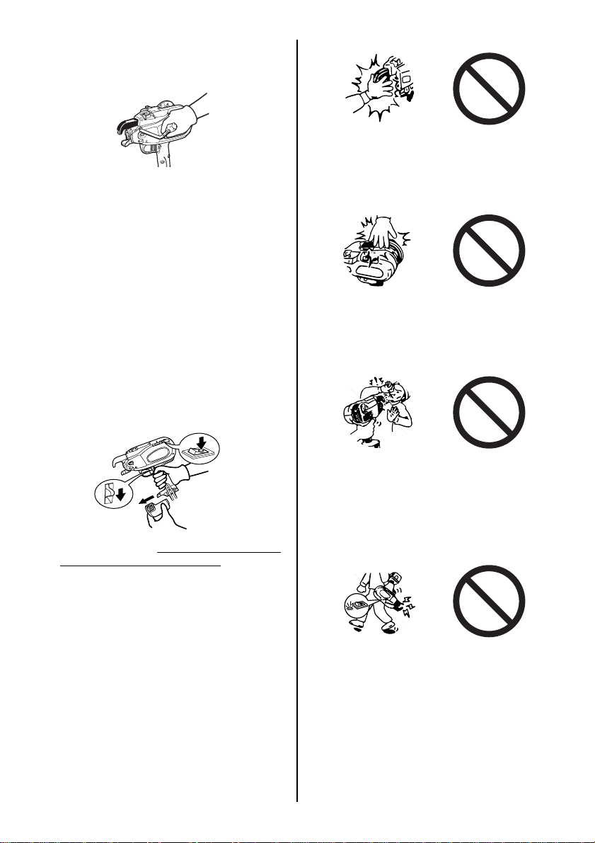
5. DO NOT POINT THE TOOL AT ANYONE
Personal injury may result if the tool catches
an operator or anyone working near him.
While working with the tool, be extremely
careful not to bring hands, legs, and other
body parts near the arm of the tool.
6. WHEN THE TOOL IS NOT IN OPERATION
KEEP YOUR FINGERS OFF THE TRIGGER
Failure to do so may cause accidental tying,
leading to serious injury.
6
Page 7

10. MAINTAIN THE TOOL IN GOOD OPERATING CONDITION
To secure operating safety and ensure top
performance, keep the tool free of wear and
damage. Also keep the tool's hand grip dry
and clean, especially free of oil and grease.
7. NEVER OPERATE THE TOOL UNDER
ANY ABNORMAL CONDITION
If the tool is not in good working order, or if
any abnormal condition is noticed, switch it
off immediately (set the Main switch at OFF),
lock the Trigger and have it examined and
repaired.
8. AFTER BATTERY INSTALLATION IF THE
TOOL OPERATES WITHOUT THE TRIGGER BEING PULLED OR THE OPERATOR NOTICES UNUSUAL HEAT, SMELL,
OR SOUND, DISCONTINUE OPERATION
Failure to do so may lead to serious injury.
Return to dealer for safety inspection.
11. USE ONLY THE AUTHORIZED BATTERY
PACK
If the tool is connected to a power supply other than the authorized pack, such as a rechargeable battery, a dry cell, or a storage
battery for use in automobiles, the tool may
be damaged, break down, overheat, or even
catch on fire. Do not connect this tool to any
power supply except the authorized battery
pack.
12. TO ENSURE MAXIMUM PERFORMANCE,
FULLY CHARGE THE BATTERY BEFORE
USE
A new battery pack or one not used for extended periods may have self-discharged
and thus may need recharging to restore it to
a fully charged condition. Before operating
the tool, make sure to charge the Battery
pack with the designated MAX Battery charger.
13. BATTERY CHARGING PRECAUTION
1 Use only MAX Battery charger and
MAX Battery Pack
Failure to do so may cause the Battery to
overheat or catch fire leading to serious
injury.
9. NEVER MODIFY THE TOOL
Modifying the tool will impair performance and
operating safety. Any modification may lead to
serious injury and void the tool warranty.
AC
120V
2 Charge the Battery from an AC 120V
wall socket
Failure to do so may result in overheating,
or inadequate charging possibly causing
serious injury.
7
Page 8

3 Never use a transformer
4 Never connect the Battery charger to
an engine generator direct-current
power supply
The charger will break down or be damaged from burning.
7 Do not put a cloth or any other cover
on the Battery charger while the Battery pack is being charged
This will cause overheating and damage
from burning, or the Charger may even
catch fire.
8 Keep the Battery pack and Battery
charger away from heat and flames
5 Avoid charging the Battery pack in the
rain, in a damp place, or where water is
splashing
Charging a damp or wet Battery pack will
cause an electric shock or a short circuit
that may lead to damage from burning
and even the tool catching on fire.
6 Do not touch the power cord or plug
with a wet hand or glove
This may cause injury from electric shock.
Thinner
Gasoline
9 Do not charge the Battery pack near
flammable materials
10Charge the Battery pack in a well ven-
tilated place
Avoid charging the Battery pack where it
will be in direct sunlight.
11Charge the Battery pack in a tempera-
ture range of 32°F (0°C) to 104°F (40°C)
8
Page 9

12Avoid continual use of the Battery
charger
Rest the Charger for 15 minutes between
charges to avoid functional trouble with
the unit.
18Put a pack cap on the terminal of the
Battery pack
When the Battery pack is not in use, put a
pack cap on its terminal to prevent short
circuits.
13Any objects that block the ventilation
holes or Battery pack receptacle may
cause electric shock or functional
troubles
Operate the charger free of dust or other
foreign materials.
14Handle the power cord carefully
Do not carry the Battery charger by its
power cord. Do not use the power cord to
disconnect it from a wall socket; this will
damage the cord and break the wires or
cause a short circuit. Do not let the power
cord contact sharp edged tools, hot materials, oil, or grease. A damaged cord must
be repaired or replaced.
15Do not charge non rechargeable bat-
teries with this charger.
16This charger is not intended for use by
children or disabled persons without
supervisor.
17Children should be supervised to en-
sure that they do not play with the
charger.
19Do not let the terminal (metal compo-
nent) of the Battery pack short-circuit
A short circuit in the terminal will generate
a large current, causing to overheat the
Battery pack and become damaged.
20Do not leave or store the tool in a vehi-
cle or in direct sunlight during summer. Leaving the tool in high
temperature conditions may cause the
battery pack to deteriorate.
21Do not store a fully discharged battery
pack. If a fully discharged battery pack
is removed from the system and left for
a long period of time, it may become
damaged. Recharge the battery immediately when it has been discharged.
14. WEAR SAFETY GLOVES WHILE OPERATING THE TOOL
The finish tie has sharp edges. To avoid serious injures, be careful not to touch the sharp
edges. MAX recommends wearing safety
gloves while operating the tool.
9
Page 10

15. PRIOR TO USING THE TOOL.
WARNING
• Make sure that the safety features function
properly. If they do not, avoid using the
tool.
Trigger
Trigger Lock
Trigger Lock
The Trigger can be locked preventing the tool
from operating for safety. Always keep the Trigger locked when not in use.
Unless you are at tying work, set the trigger lock
to the position of LOCK and remove a battery
pack. When you start tying work, set it to the position of UNLOCK.
Curl Guide
Curl Guide
When the Curl Guide is opened, it will emit a
beeping sound and the tool does not operate.
Pull to the left slightly and upwards to UNLOCK.
10
Page 11

3. SPECIFICATIONS AND TECHNICAL DATA
1. NAME OF PARTS
Reel stopper
Tie-Wire
Battery pack
entry point
Production
number
Reel holder
LED lamps (Red and Green)
Charging status indicator lamps
LED lamp (Orange)
Charging status indicator lamp
Release lever
Release stopper
Arm
Curl guide
Window
Trigger
Torque and wrap dial(RB517)
Torque dial (RB397)
Feed dial (RB217)
LED
Main
switch
Trigger lock
Grip
Battery pack
(JPL91430A)
Latch
Belt hook
Tightening
Torque
13.1lbF·inch
(150cNm)
Terminal
Power cord
Power plug
Power cord of JC925 is removable from the charger.
Pack cap
Battery pack (JPL91430A)
2. TOOL SPECIFICATIONS
PRODUCT NO. RB517 RB397 RB217
WEIGHT 5.3lbs (2.4kg) (Battery in-
HEIGHT 12" (305mm) 12" (305mm) 12" (305mm)
WIDTH 4-1/8" (105mm) 4-1/8" (105mm) 4-1/8" (105mm)
LENGTH 12" (305mm) 11-3/8" (290mm) 10-5/8" (270mm)
WRAPS PER TIE 3 or 4 Wraps/tie 3 Wraps/tie
BATTERY Li-ion14.4V/(JPL91430A)
ACCESSORIES Battery pack JPL91430A (2pc.)
Operating temperature 14°F to 104°F (-10°C to 40°C)
Humidity 80% RH or less
cluded)
Battery Charger JC
Carrying case, Belt hook
Instruction video and instruction manual DVD
925
5.3lbs (2.4kg) (Battery included)
5.3lbs (2.4kg) (Battery included)
11
Page 12

<Battery charger>
Product name LITHIUM ION BATTERY CHARGER
Product code JC925
Input AC120 V 60 Hz 2.6 A 160W
Output DC14.4V 7.5A
DC18V 5.4A
DC25.2V 4.5A
Weight 3.3 lbs (1.5 kg)
Operating temperature range 32 °F to 104 °F (0 °C to 40 °C)
Operating humidity range 80% RH or less
<Battery pack>
Product name LITHIUM ION BATTERY PACK
Product code JPL91430A
Battery type Lithium ion battery
Nominal voltage DC14.4 V (3.6V x 4 cells)
Nominal capacity 3.0 Ah (3,000 mAh)
Charging time
(When charger JC925 is used)
Quick charging - Approximately 30 minutes (Approximately 90%
of capacity)
Full charging - Approximately 45 minutes (100% of capacity)
Accessories Pack cap (For preventing short circuit)
Weight 1.1 lbs (0.5 kg)
Charging temperature 32 °F to 104 °F (0 °C to 40 °C)
Operating temperature 32 °F to 104 °F (0 °C to 40 °C)
Operating humidity range 80% RH or less
3. WIRE SPECIFICATIONS
MODEL RB517 RB397
TIE WIRE TW897A TW897A-PC TW897A TW897A-EG TW897A-PC
DIAMETER 21 GA (0.8mm) 21 GA (0.8mm)
21 GA (0.8mm) 21 GA (0.8mm) 21 GA (0.8mm)
LENGTH 312 feet 279 feet 312 feet 295 feet 279 feet
TIES PER COIL (3 Wraps/tie)
Approx. 90 ties
(4 Wraps/tie)
Approx. 75 ties
TIES PER
CHARGE
(3 Wraps/tie)Approx. 1,800 ties
(4 Wraps/tie)Approx. 1,700 ties
(3 Wraps/tie)
Approx. 80 ties
(4 Wraps/tie)
Approx. 65 ties
Approx.
120 ties
Approx.
110 ties
Approx. 2,000 ties
Approx.
100 ties
MODEL RB217
TIE WIRE TW897A TW897A-EG
DIAMETER 21 GA (0.8 mm) 21 GA (0.8 mm)
LENGTH 312 feet 295 feet
TIES PER COIL Approx. 170-210 ties Approx. 155-190 ties
TIES PER CHARGE Approx. 2,000 ties
BATTERY CHARGER:
Use only an authorized Battery charger, MAX JC925.
12
Page 13

4. TECHNICAL DATA
1 NOISE
A-weighted single-event ------ LWA, 1s, d 84 dB
sound power level
A-weighted single event ------ LpA, 1s, d 73 dB
emission sound pressure
level at work station
These values are determined and documented in accordance to EN60745-1 : 2006.
2 VIBRATION
Vibration characteristic value - 1.8 m/s
2
These values are determined and documented in accordance to ISO 5349-1 and ISO 5349-2.
This value is a tool-related characteristic value and does not represent the influence to the handarm-system when using the tool. An influence to the hand-arm-system when using the tool will, for
example, depend on the gripping force, the contact pressure force, the working direction, the adjustment of main supply, the workpiece, the workpiece support.
3 RADIATED EMISSION 30-1000 MHZ
Class B
4 Overvoltage category
category 1 according to IEC 60664-1
5 Pollution degree
degree 4 according to IEC 60664-1
6 Design guidelines
Machinery directive Annex 1, EN 60745-1, EN 60745-2-18
5. APPLICATIONS
* Precast plants
* Commercial buildings
* Foundations
* Road & bridge
6. APPLICABLE BAR SIZES
Minimum Maximum
RB517 #5 × #5 (D16 × D16) #7 × #8 (D22 × D25)
RB397 #3 × #3 (D10 × D10) #5 × #6 (D16 × D19)
RB217 Mesh × Mesh #3 × #3 (D10 × D10)
7. ABOUT PRODUCTION YEAR
This product bears production number in the body. The two digits of the number from left indicates
the production year.
(Example)
08826035D
Year 2008
13
Page 14

4. BATTERY INSTRUCTIONS
1. Charging
OFF
LOCK
WARNING
• Before removing the Battery pack from the
tool, set the Main switch at OFF and lock
the Trigger.
Pack cap
Battery pack
Latch
When charging the Battery pack, remove it by
pushing on its latches from both sides while firmly holding the grip of the tool.
Red charging lamp
1 A Pack cap that is used to prevent short cir-
cuits must be removed from the terminal of
the Battery pack.
Charger
2 Plug the charger into a wall socket (120V).
The red light, a current-carrying indicator,
will flash on and off with two short (Pipi) beep
sounds.
Orange standby lamp
When the orange standby light is lit
When the Battery pack is hot (after continuous
use or exposure to direct sunlight) the Charger
will automatically switch to standby to protect the
Battery. The orange standby light will be lit until
the Battery’s temperature lowers to a safe level,
The Battery will then be charged automatically.
14
Page 15

When the Battery pack is at low temperature
When the Battery pack is at low temperature, its
charging is automatically suspended until its temperature increases (higher than 32°F (0°C)), in
order to protect it, even if it is set in the Charger.
Leave the Battery pack at normal temperature in
the room for some time, and then, charge it again.
When the orange standby light blinks
This indicates the Battery cannot be charged.
Unplug the Charger and check the charging receptacle. If there are any foreign objects, remove
them with a soft dry cloth. If the orange light still
blinks or there are no foreign objects, there may
be a problem with the battery or charger. Return
to dealer for service.
Battery pack
The green lamp blinks.
Battery has been recharged 90%
4 When the battery pack has been recharged,
the "red" lamp turns off and the "green" lamp
blinks.
The "green" LED lamp blinks slowly and a
long beep sounds for approximately 2 seconds. Now, the battery has been recharged
to approximately 90% of its capacity. Quick
charging takes approximately 30 minutes
(however, the recharging time and capacity
slightly change depending on the ambient
temperature and power voltage).
The green lamp remains lit.
Orange
Charger
3 Charge the Battery pack.
(1) Fully insert the Battery into the receptacle on
the Charger until it sits securely on the end.
(2) Charging will start automatically and will be
indicated by the red charging light with beeps.
(3) Charging time is approximately 30 minutes
(90% capacity). This will vary by temperature
and source voltage.
(4) For batteries those are at low temperatures
(50°F (10°C) or lower), charging time must
be extended longer. When charging at low
temperatures, both of the red and the orange
charging light will be lit.
standby lamp
Red charging lamp
Battery has been "fully" recharged.
You can use the battery pack when quick
charging is complete. However, if you leave
the battery pack on the charger, recharging
will continue. When the battery is fully recharged (to 100% capacity), the "green" LED
lamp lights up (and a long beep sounds for
approximately 2 seconds).
15
Page 16

(1) After you have recharged the battery pack,
remove it from the charger.
(2) Unplug the charger power cord from the wall
socket.
Regarding tying times per charge, a brand-new
battery ties approximately 2,000 times per charge
(RB517:Approx,1,600-1,800 times per charge).
The tying times per charge will be decreased
gradually by repeated re-charge until the Battery
becomes unusable. The tying times per charge
depend on temperature and the Battery condition.
CAUTION
• When the battery pack is fully discharged, do
not leave it for a long time without recharging.
If the fully discharged battery pack is removed
from the system and left for a long period of
time, the battery pack may become damaged.
Recharge the battery immediately when it has
been discharged.
• Do not leave the battery pack on the charger.
If the above is not observed, a weak current
will continue to flow and the battery pack may
become damaged. When recharging is complete, always remove the battery pack from the
charger.
Battery pack /Charger breakdowns
If the following conditions occur, bring the Battery and Charger to your dealer.
• The red charging lamp does not flash when the
charger plug is inserted into main power
source outlet (When the Battery pack is not inserted in the charger).
• Neither the red charging lamp nor the orange
standby lamp lights or flashes when the Battery pack is inserted in the charger.
• The orange standby lamp does not change to
the red charging lamp even after more than 1
hour. (except at low temperatures)
• The red charging lamp does not change from
constant to flashing light even after more than
90 minutes. (except at low temperatures)
16
Page 17

Indication of Quick Charger Lamps
Charger LED lamp Buzzer sound Recharging status
Red lamp blinks.
It blinks every second.
Red lamp lights.
It remains lit.
The green lamp blinks.
It blinks every second.
The green lamp lights up.
It remains lit.
The red lamp lights up.
The orange lamp lights up.
They remain lit.
The orange lamp lights up.
It remains lit.
The orange lamp blinks.
It blinks quickly (0.1 sec
ON and 0.1 sec OFF).
∗
For batteries those are at low temperatures (50°F (10°C) or lower), charging time must be extended longer.
The power cord is plugged
into the receptacle.
Two short beeps (Pi, pi)
The battery pack is mounted.
One short beep (Pi)
The battery has been re-
charged.
A long beep for approx. 2
seconds (Piii...)
Fully recharged.
A long beep for approx. 2
seconds (Piii...)
— Protective charging
— Standby
Not possible to recharge.
Short continuous beeps for
approx. 10 seconds
(Pi, pi, pi, pi,...)
The charger is
powered.
The battery is being recharged.
The battery has
been recharged.
Battery is "fully" recharged.
Not possible to recharge.
The charger power cord is plugged
into a wall socket.
Quick recharging continues.
The battery has been recharged to approx. 90% of its capacity.
If you leave the battery pack on the
charger, recharging will continue.
Recharged to 100% capacity.
The battery is recharged with a low
current to protect the charger and battery.
If the temperature of the battery pack
is too high: Battery recharging starts
automatically when the temperature
drops below the limit.
If the temperature of the battery pack
is too low: Place the battery pack in a
room temperature location for a while,
then retry recharging it.
Unable to recharge the battery.
The battery pack slot is contaminated,
or the battery pack has failed.
About the Battery Level Indicator
Battery level check button
Battery level gauge
1 To check the battery level (excluding while charging or while operating the charging
tool), press the battery level check button.
2 The battery level gauge lights up according the then battery level.
Battery level
indication
Battery level:0%Battery level:
about 0 to 10%
All indicators
OFF
One red
indicator blinks
Battery level:
about 10 to 40%
One red
indicator ON
17
Battery level:
about 40 to 70%
Two red
indicators ON
Battery level:
about 70 to 100%
Three red
indicators ON
Page 18

Service Life of the Battery Pack
If any condition described below is observed, the
battery pack is at the end of its service life. Replace it with a new one.
• Although the battery pack has been properly
charged (fully charged), a great drop in tying
time has been noticed.
CAUTION
Do not charge the battery pack when this happens. If the motor’s rotational speed slows
down, the power of the battery pack is considered to be nearly depleted. Using the tool
more will cause it to overdischarge, resulting
in a shortened service life of the battery pack
and also in functional trouble of the tool’s
main body.
5. OPERATING INSTRUCTIONS
OFF
LOCK
1. How to set the Tie-Wire
WARNING
• Be sure to set the Main switch to off, to lock
the Trigger, and detach the Battery pack.
CAUTION
Do not use a battery pack when its service life
is finished.
This will cause functional trouble in the tool’s
main body. Also charging a battery pack that
is out of service life will lead to functional trouble in the battery charger.
Recycling a Li-ion Battery
The MAX battery pack uses a Li-ion battery, it
may be illegal to dispose of this battery into the
municipal waste system. Check with your local
solid waste officials for details in your area for recycling options or proper disposal.
CAUTION
When disposing of the battery pack, make
sure to put a pack cap on its ter m inal (with insulating tape securing it) to prevent short circuits.
Release Stopper
1 Press the Release Lever of this equipment,
and confirm that the Release Lever is caught
in the Release Stopper.
18
Release Lever
Page 19

Tie-Wire
Reel Stopper
Tie-Wire
2 Peel off the tape fixing Tie-Wire by about
2" (5cm). Stretch out the tip of the wound
Tie-Wire.
BE SURE TO USE ONLY THE SPECIFIED TIEWIRE (MAX TW897A).
The use of binding wire that has not been specified may cause breakdown of this equipment.
Therefore, be sure only to use the specified MAX
TW897A. Do not use binding wire that has become rusted, since the use of rusted wire will
cause equipment breakdown.
∗ TW897, old wire reel cannot be used.
Reel stopper
Reel holder
3 Push the reel stopper to release the reel
holder.
Reel
holder
4 Set the Tie-Wire in the tool by matching the
side of the Tie-Wire as shown in the picture.
Then slide the Reel stopper so that the Reel
Holder can be pushed in the Reel. Then
push the Reel Holder and fix it by sliding the
Reel stopper.
Feeding gears
Pipe
Wire guide
5 Insert the tip of the stretched out Tie-Wire
into the Wire Guide. Then put it into the Pipe.
WARNING
• Put the Wire around 4" (10cm) inside the
Pipe.
• The tip of the Tie-Wire should be straight-
ened out to allow it to pass through the wire
feeding mechanism.
When mounting the Tie-Wire, the wire may
become jammed inside the machine if the
wire tip is bent.
19
Page 20

If the window is dirty and the pipe position can not be confirmed
Open the window and wipe off the dirt on the inside of the window with a soft cloth, etc. Close
the window again after cleaning to ensure that
foreign objects will not be able to enter the machine.
Feeding gears
Tie-Wire
Release lever
Release stopper
6 Release the release stopper, and confirm
that the release lever has returned to its original position and that the feeding gears are
clamping the Tie-Wire. This completes the
Tie-Wire mounting operation.
Tie-Wire
WARNING
• When setting the main switch to ON, abso-
lutely do not bring your fingers close to the
binding part and rotating part of the tool's
tip.
• Do not switch the main switch ON and OFF
in rapid succession, since this operation
will cause machine breakdowns.
• Do not touch
work (while the machine is operating).
the Tie-Wire during the tying
7
Remove the tape from the tie-wire completely.
8 Remove slack from wire spool.
Make sure the Tie-Wire d oes not get ca ught behind the wire spool .This could lead to jamming.
9 Mount the battery pack on the tool's main
body until a click is heard. Turn the Main
Switch ON.
20
Page 21

RB517
RB217
0 Tool feeds the wire about 6" (150 mm) and
cuts the wire automatically.Remove the cut
end of the wire with pliers.
2. How to remove the Tie-Wire
OFF
LOCK
WARNING
• Be sure to turn the Main switch OFF, lock
the Trigger, and remove the Battery pack.
Trigger
Trigger lock
a Unlock the Trigger before using the tool.
Release Stopper
Release Lever
1 Press the release lever, and confirm that the
release lever is caught in the release stopper.
Wire guide
Tie-Wire
2 Remove the Tie-Wire from the wire guide.
21
Page 22

Tie-Wire
Reel
stopper
3 Slide the Reel stopper to release the Reel
holder and remove the Tie-Wire.
4 Mount the new Tie-Wire. (Refer to the Tie-
Wire mounting method explanation.)
When the Tie-Wire runs out of binding wire
There should be around 12" (300 mm) of the TieWire left at end of the spool. This should be discharged with the old spool and be replaced with
a new one.
3. Auto Power-off feature
This Re-bar Tier have "Auto Power-off" feature, which saves the power consumption of
the Li-ion battery when the tool is not operated.
If the tool is not operated for 30 minutes, the tool
is automatically turned off. This is "Auto Poweroff".
When the power is turned off automatically, turn
the main switch OFF, then turn ON the switch
again to operate the tool.
4. Tension and wrap adjustment
RB517
OFF
1 Be sure to turn the Main switch OFF, to lock
the Trigger and detach the Battery pack.
22
Page 23

Torque and wrap dial
2 This dial allows you to set 3 wraps / tie or 4
wraps / tie and also you can adjust the
torque.
To increase the tension, turn it in the counterclockwise.
To decrease the tension, turn it in the clockwise.
WARNING
• When setting the main switch to ON, abso-
lutely do not bring your hand close to the
binding part or rotating part of the tip of the
tool.
4 Set the Trigger Lock to UNLOCK and turn on
the main switch.
Reinforcing bars Over-tightened
3 Insert the charged battery pack into the tool
until a click is heard.
Appropriate
5 Test the tool again to check the tie strength.
6 If the tie strength is not appropriate, repeat
procedures 1~5.
23
Page 24

4. Tension adjustment
RB397
OFF
1 Be sure to turn the Main switch OFF, to lock
the Trigger and detach the Battery pack.
Torque dial
WARNING
• When setting the main switch to ON, abso-
lutely do not bring your hand close to the
binding part or rotating part of the tip of the
tool.
4 Set the Trigger Lock to UNLOCK and turn on
the main switch.
2 This dial allows you to adjust wire tension
torque slightly.
To increase the tension, turn it in the counterclockwise.
To decrease the tension, turn it in the clockwise.
3 Insert the charged battery pack into the tool
until a click is heard.
Reinforcing bars Over-tightened
Appropriate
5 Test the tool again to check the tie strength.
6 If the tie strength is not appropriate, repeat
procedures 1~5.
24
Page 25

4. Wire length adjustment
1 Be sure to turn the main switch OFF, to lock
the trigger and detach the battery pack.
Feed dial
RB217
OFF
3 Mount the battery pack on the tool's main
body insert the charged battery pack on to
the main unit until a click is heard.
Edge part
Edge part
110
2 The feed dial is a mechanism to adjust feed
rate of the Tie-Wire. When the edge part
length is not appropriate after binding, use
this dial to adjust it.
WARNING
• When setting the main switch to ON, abso-
lutely do not bring your hand close to the
binding part or rotating part of the tip of the
tool.
4 Set the Trigger Lock to UNLOCK and turn on
the main switch.
5 Test the tool again to check the tie strength.
25
Page 26

5. For proper tightness
45°
Arm
1 Tilt the tool 45° angle to the crossed re-bars.
4 Cross tie.
Bent the tail of the first tie before making the
second tie.
Arm
Re-bars
2 Apply the tool perpendicularly to the surface
of the crossed re-bars.
During tool operation
• Do not move the tool during tying operation until the tool stops tying automatically.
3 Tie in alternate direction.
5 When you need extra tightness, place re-
bars at the top of the Arm part.
26
Page 27

6. MAINTENANCE
1 Regularly inspect the tool
In order to maintain the performance of the
tool, periodically clean up and inspect the
tool.
2 Do not lubricate the equipment
Absolutely do not lubricate this equipment.
Applying lubrication will remove the grease
inside of the tool, and cause problem on the
tool.
3 Regularly clean the feeding mechanism
In order to maintain the performance of the
tool, periodically clean up the mechanism
around the feed gear. Using the Air Duster or
like, blow the dust and the iron sand off
around the feed gear.
7. CLEANING MANUAL
When the machine operates for long hours, dust
and wire cuttings may adhere to the cutter section. In such a case, disassemble and clean the
machine according to the following procedure.
(If a wire is caught in the cutter section or wire
guide A, the wire can be removed according to
the same procedure.)
Disassembling
CAUTION
• Do not remove the 2 uncoated bolts.
1. Loosen the 2 (plated) hexagon socket
head bolts M3 × 6.
RB397
Hexagon socket head bolt M3 × 6
(plated)
Arm B
Hexagon socket head
bolt M3 × 6 (plated)
Arm B
Cutter plate unit
Cutter
Fixed cutter
2. Remove arm B and the 2 (plated) hexagon
socket head bolts M3 × 6.
27
Wire guide A
Page 28

Cutter plate unit
Fixed cutter
Cutter
Cutter
Reverse side
of the cutter
Integrated unit of
the cutter
and pin
Wire guide A
3. Remove the cutter and the fixed cutter,
and clean them. (The removable parts are
the cutter, fixed cutter, wire guide A and
cutter plate unit.)
Assembling
Cutter con rod hole
Large hole
Cutter plate unit
Small hole
Fixed cutter
Wire guide A
5. Fit the cutter and assemble wire guide A.
Arm B
Wire guide B
Pipe
Groove
CAUTION
• Assemble the fixed cutter so that the large hole
is set to the rear side and the small hole (long
hole) is set to the top side.
Rear side Top side
4. Put the pin of the cutter plate unit through
the cutter con rod hole and assemble the
fixed cutter to the unit.
6. Align the groove of wire guide B attached
to arm B with the pipe, and assemble arm
B.
28
Page 29

Hexagon socket head bolt
M3 × 6 (plated)
Good
Disassembling
RB517
Hexagon socket head bolt
M3 × 5 (plated)
RB217
Arm B
WIRE
GUIDE A
The outer parts are
aligned with each other.
The outer parts are not
aligned.
No gap
No good
Gap
7. Make sure that arm B is securely assembled and tighten the 2 (plated) hexagon
socket head bolts M3 × 6. (Tightening
torque: 15.2lbF·inch (172cN·m))
CAUTION
• Are there any loosening parts?
Make sure that the outer parts are aligned and
the parts are securely assembled without any
gap between them.
1. Loosen the 2 (plated) hexagon socket
head bolts M3 × 5.
Hexagon socket head
bolt M3 × 5 (plated)
Fixed cutter
Step pin
Cutter
Washer 3
Arm B
×
7
2. Remove arm B and the 2 (plated) hexagon
socket head bolts M3 × 5.
Cutter con rod
Step pin
Cutter
Fixed cutter
3. Remove the cutter and the fixed cutter,
and clean them. (The removable parts are
the cutter, fixed cutter and step pin.)
29
Page 30

Assembling
Fixed cutter
Hexagon socket head bolt M3 × 5 (plated)
Cutter
Large hole
Small hole
CAUTION
• Assemble the fixed cutter so that the large hole
is set to the rear side and the small hole is set
to the top side.
Rear side Top side
step pin
Loose insertion
of the pin
Washer 3 × 7
5. Make sure that arm B is securely assembled and tighten the 2 (plated) hexagon
socket head bolts M3 × 5. (Tightening
torque: 15.2lbF·inch (172cN·m))
CAUTION
• The (right) bolt should have the captive wash-
er. Install the washer first and then tighten the
bolt.
4. Insert the step pin into the hole and then
into the connecting rod hole.
30
Page 31

8. STORAGE
Do not store the tool in a cold weather environment. Keep the tool in a warm area.
When not in use, the tool should be stored in a
warm and dry place. Keep out of reach of children. All quality tools will eventually require servicing or replacement of parts because of wear
from normal use.
REMOVE REEL OF TIE-WIRE
When you have finished the Tie-Wire, remove
the Tie-Wire from the tool.
STORE THE TOOL
When you have finished tying work or when the
tool will not be used for a while, switch off the tool,
make sure the motor has stopped, lock the trigger, and remove the battery pack. Tool, attachments and accessories should be stored in a w ellventilated dry place where the temperature will
not exceed 104°F (40°C).
The battery pack, with a pack cap installed on the
pack's terminal to prevent short circuits, should be
stored in a well-ventilated dry place where the
temperature will not exceed 86°F (30°C).
31
Page 32

9. TROUBLE SHOOTING/REPAIRS
The troubleshooting and/or repairs shall be carried out only by the MAX CO., LTD. authorized distributors or by other specialists.
This tool alerts you to the following conditions by means of a warning sound and warning lamp. The
warning lamp is illuminated or blinks, and is interlocked with the warning sound. Take a countermeasure
according to the following table.
WARNING
• If any of the following conditions occur, be sure to set the Main switch to OFF before carrying
out the countermeasures.
• When setting the Main switch to ON, do not touch the tying part of rotating part of the tool's tip.
If the problem is not solved by carrying out the following countermeasures, be sure to set the
Main switch to OFF and then contact the dealer where the equipment was purchased or MAX
CO., LTD. authorized distributors.
No. Normal Operation Problem
1. Power ON → The
Tip Axis is initialized
and the wire-cutter
operates automatically.
2. Power On → LED
lamp is lit. → No operation over 30 minutes → LED lamp
goes off. → Although pulling the
trigger, no operation takes place.
3. Trigger ON → Wire
sent out.
No operation
takes place.
No operation
takes place, although pulling
the trigger
No sending of
wire takes place.
Warning
Sound
No sound
emitted.
A long beep
(Piii...)
Continuous
short beeps
(Pi, pi, pi, ...)
Two short
beeps repeated for 10 seconds (Pipi,
Pipi, ...), then
power off automatically
A short beep
(Pi), (before
LED lamp
goes off)
A long beep
(Piii...)
Three short
beeps repeated
(Pipipi,
pipipi, ...)
Five short
beeps
(Pipipipipi,
pipipipipi)
Cause What to Check Solution
Dead battery (Completely empty)
Electrode plate has
been oxidized.
Curl guide is left
open.
Binding wire has
been entangled
around Twist section.
Battery is empty. Confirm the battery is
The battery pack is
inserted when the
Main switch is ON.
Normal operation.
(SEE PAGE 22)
Curl guide is left
open.
Tie-Wire has been
run out.
Wire caught inside
reel.
Cutter section is
blocked with foreign
substance.
A wire is caught in
the cutter section or
wire guide A.
Motor has been
heated.
Confirm the battery is
charged.
Taking out the battery,
see if electrode has been
browned.
Open/close curl guide Fully close curl guide.
Turn off power and take
out battery to confirm if
binding wire has been
entangled inside curl
guide.
charged.
Make sure to insert the
battery pack, only when
the Main switch is OFF.
Set the Main switch to
OFF, then ON.
Open/close curl guide Fully close curl guide.
Check if the Tie-Wire has
been run out or not.
Check if wire inside reel
has been loosened and
caught.
Confirm functioning of
Cutter section.
Check if any wire is
caught.
Warning sound does not
go continuously. It occurs
only when trigger is
pulled.
Perform normal charge.
(SEE PAGE 14)
Polish terminal part of
battery pack with dry
cloth, etc.
Turning off power, remove binding wire inside
curl guide.
Perform normal charge.
(SEE PAGE 14)
Set the Main switch to
OFF, then ON.
Set the Main switch to
OFF, then ON.
Set the new Tie-Wire.
Remove fray on reel.
Either wipe Cutter section with dry cloth or blow
it with air.
Disassemble the cutter
section and remove the
caught wire. (SEE PAGE
27)
Halt Machine and cool it
down.
32
Page 33

No. Normal Operation Problem
3. Trigger ON → Wire
sent out.
4. Binding wire draws
a circle.
5. Wire is subject to
cutting.
6. Wire twisting takes
place.
Sending of wire
is stopped halfway.
Curl is disordered and steps
out of curl guide.
No wire cutting
takes place.
Wire gets entangled.
Binding power is
weak.
Twisting-off
takes place.
Works properly Two short
Warning
Sound
Four short
beeps repeated
(Pipipipi,
pipipipi, ...)
Three short
beeps repeated
(Pipipi,
pipipi, ...)
No sound
emitted.
No sound
emitted.
No sound
emitted.
A short beep
and a long
beep, repeatedly.
(Pipipipipipi...)
No sound
emitted.
No sound
emitted.
beeps.
(Pipi)
Cause What to Check Solution
Tie-Wire is not set in
the tool.
Binding wire not of
designated types
has been used.
Binding wire has
been entangled inside reel.
Wire, by hitting Reinforcing bars, was repelled.
Cutter section is
blocked with foreign
substance.
Wire, by hitting Reinforcing bars, was repelted.
Binding wire has
been entangled
around Twist section.
Reinforcing bars is
not of designated
size.
Erroneous handling
such as improper application of Machine.
Function of curl
guide switch
Reinforcing bars is
not of designated
size.
Erroneous handling
such as improper application of Machine.
Low power remains
in the Battery pack.
The tool is used at
low temperature.
Check if the Tie-Wire has
been set in the tool.
Confirm reel side face. Use MAX Tie-Wire
Confirm reel winding Remove fray on reel.
Check if wire hits Reinforcing bars at binding.
Confirm function of Cutter section.
Check if wire hits Reinforcing bars at binding.
Turn off power and take
out battery to confirm if
binding wire has been
entangled inside curl
guide.
Confirm size of Reinforcing bars to be bound.
(SEE PAGE 13)
Confirm how to apply Machine to Reinforcing bars.
Check if curl guide is left
open at binding.
Confirm size of Reinforcing bars at binding.
(SEE PAGE 13)
Confirm how to apply Machine to Reinforcing bars.
Confirm the battery is fully charged.
Check the temperature at
the job site.
Set the Tie-Wire.
TW897A.
Pay attention so that
wire does not hit Reinforcing bars at binding.
Either wipe Cutter section with dry cloth or blow
it with air.
Pay attention so that
wire does not hit Reinforcing bars at binding.
(SEE PAGE 26)
Turning off power, remove binding wire inside
curl guide.
Use appropriate diameter scope.
Turning Torque dial in +
and inserting in vertical
direction, use as tilting at
45°. (SEE PAGE 24
AND 26)
Do not operate Machine
until binding is completed.
Use appropriate diameter scope.
Turning Torque dial in –
(minus) and inserting in
vertical direction, use as
tilting at 45°. (SEE PAGE
24 AND 26)
Perform normal charge
after the tying speed
slows down considerably.
Leave the tool and the
battery pack at normal
temperature in the room
for some time, and then
continue the operation.
33
Page 34

• The content of this manual might be changed without notice for improvement.
ATTENTION:
The product you have purchased is powered by a Li-ion battery which is recyclable. At the end of its useful life, under various state and local laws, it is illegal to dispose of this battery into your municipal waste
stream. Please call 1-800-8-BATTERY for information on how to recycle this battery.
257 East 2nd Street
Mineola, NY 11501, U.S.A.
TEL: 1-800-223-4293
FAX: (516)741-3272
www.maxusacorp.com (USA Site)
wis.max-ltd.co.jp/int/ (GLOBAL Site)
4010293
120627-00/00
PRINTED IN JAPAN
 Loading...