

Page 1
PASJ30(CE)
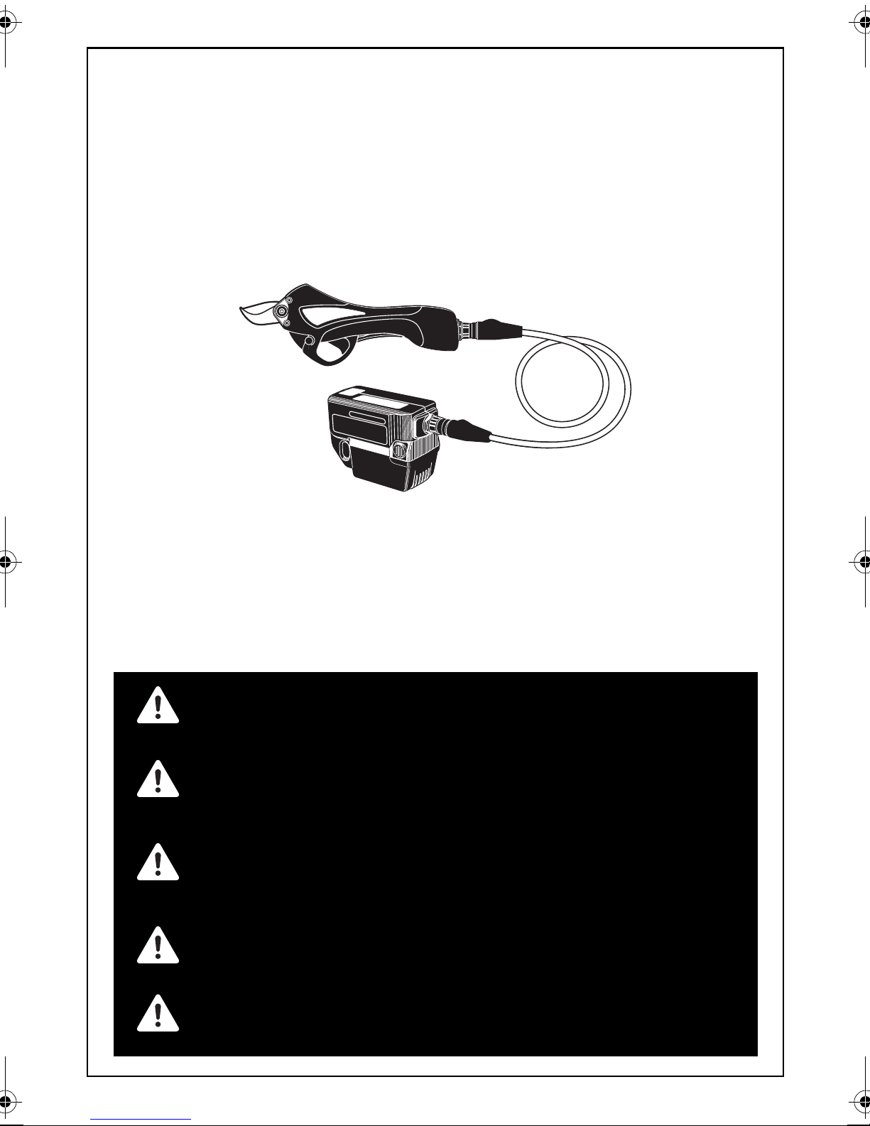
CORDLESS PRUNING SHEARS
AKKU-GARTENSCHERE
CISAILLES A ELAGER SANS FIL
CESOIA DA POTATURA A BATTERIA
PODADERA INALÁMBRICA
MANUALE DI FUNZIONAMENTO E MANUTENZIONE
MANUAL DE OPERACIONES Y MANTENIMIENTO
WARNING
WARNUNG
AVERTISSEMENT
ATTENZIONE
ADVERTENCIA
OPERATING AND MAINTENANCE MANUAL
BETRIEBSANLEITUNG
MANUEL D'UTILISATION ET D'ENTRETIEN
Original Language English
BEFORE USING THIS TOOL, STUDY THIS MANUAL TO ENSURE SAFETY WARNING
AND INSTRUCTIONS.
KEEP THESE INSTRUCTIONS WITH THE TOOL FOR FUTURE REFERENCE.
LESEN SIE VOR INBETRIEBNAHME DES GERÄTES DIE GEBRAUCHS- UND SICHERHEITSHINWEISE.BITTE BEWAHREN SIE DIE GEBRAUCHS- UND SICHERHEITSHINWEISE AUF, DAMIT SIE AUCH SPÄTER EINGESEHEN WERDEN KÖNNEN.
AVANT D’UTILISER CET OUTIL, LIRE CE MANUEL ET LES CONSIGNES DE SÉCURITÉ AFIN DE
GARANTIR UN FONCTIONNEMENT SÛR.
CONSERVER CE MANUEL EN LIEU SÛR AVEC L’OUTIL AFIN DE POUVOIR LE CONSULTER
ULTÉRIEUREMENT.
PRIMA DI USARE QUESTA MACCHINA, STUDIARE IL MANUALE PER PRENDERE ATTO DEGLI
AVVERTIMENTI E DELLE ISTRUZIONIPER LA SICUREZZA.
TENERE QUESTE ISTRUZIONI INSIEME ALLO STRUMENTO PER CONSULTAZIONI FUTURE.
ANTES DE UTILIZAR ESTA HERRAMIENTA, LEA DETENIDAMENTE ESTE MANUAL PARA
FAMILIARIZARSE CON LAS ADVERTENCIAS E INSTRUCCIONES DE SEGURIDAD.
CONSERVE ESTAS INSTRUCCIONES JUNTO CON LA HERRAMIENTA PARA FUTURAS CONSULTAS.
Page 2

INDEX INHALTSVERZEICHNIS TABLE DES MATIÈRES INDICE ÍNDICE
ENGLISH Page 9 to 28
DEUTSCH Page 29 to 48
FRANÇAIS Page 49 to 68
ITALIANO Page 69 to 88
ESPAÑOL Page 89 to 108
EC DECLARATION OF CONFORMITY Page 111
www.max-europe.com
DEFINITIONS OF SIGNAL WORDS
WARNING: Indicates a potentially hazardous situation which, if not avoided, could result in death or
serious injury.
CAUTION: Indicates a potentially hazardous situation which, if not avoided, may result in minor or
moderate injury.
NOTE: Emphasizes essential information.
DEFINITIONEN DER HINWEISBEZEICHNUNGEN
WARNUNG: Zeigt eine eventuell gefährliche Situation an, die den Tod oder schwere
Verletzungen zur Folge haben könnte, wenn sie nicht vermieden wird.
VORSICHT: Zeigt eine eventuell gefährliche Situation an, die leichte oder mittelschwere
Verletzungen zur Folge haben könnte, wenn sie nicht vermieden wird.
HINWEIS: Hebt wichtige Informationen hervor.
DÉFINITIONS DES DIFFÉRENTS DEGRÉS D’ AVERTISSEMENTS
AVERTISSEMENT: Indique une situation éventuellement dangereuse qui, si elle n’est pas
contournée, pourrait provoquer la mort ou des blessure sérieuses.
ATTENTION:
REMARQUE: Souligne des informations importantes.
DEFINIZIONE DELLE INDICAZIONI DI AVVERTIMENTO
ATTENZIONE: Indica l’eventualità che possa verificarsi una situazione pericolosa, la quale se
AVVERTENZA: Indica l’eventualità che possa verificarsi una situazione pericolosa, la quale se
NOTA: Evidenzia informazioni importanti.
DEFINICIÓN DE LAS INDICACIONES DE ADVERTENCIA
ADVERTENCIA: Indica una situación potencialmente peligrosa que podría causar la muerte o
PRECAUCIÓN: Indica una situación potencialmente peligrosa que podría causar lesiones menos
NOTA: Resalta informaciones importantes.
Indique une situation éventuellement dangereuse qui, si elle n’est pas contournée,
pourrait provoquer des blessures légères à moyennement sérieuses.
non viene evitata, può risultare letale o provocare gravi lesioni.
non viene evitata, può provocare lesioni di lieve o media entità.
graves lesiones si no se evita.
graves o leves si no se evita.
2
Page 3
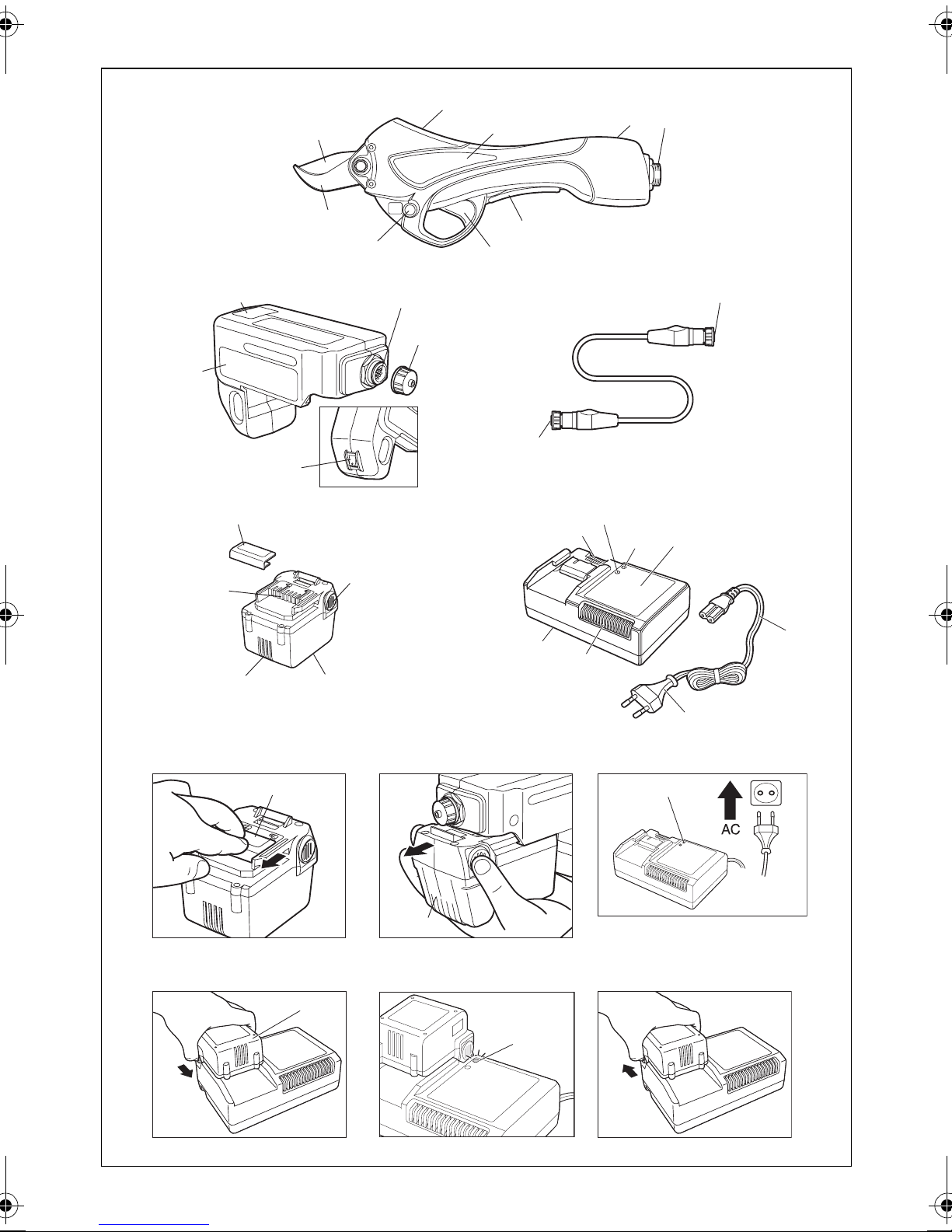
Fig.A/Abb.A
1
3
50
51
7
2
4
Fig.B/Abb.B Fig.C/Abb.C
8
10
6
5
9
52
12
11
Fig.D/Abb.D Fig.E/Abb.E
14
13
15
21
1716
18
22
20
19
12
53
24
Fig.F/Abb.F Fig.G/Abb.G Fig.H/Abb.H
13
19
25
Fig.I/Abb.I Fig.J, K, L/Abb.J, K, L Fig.M/Abb.M
25
19
23
3
Page 4
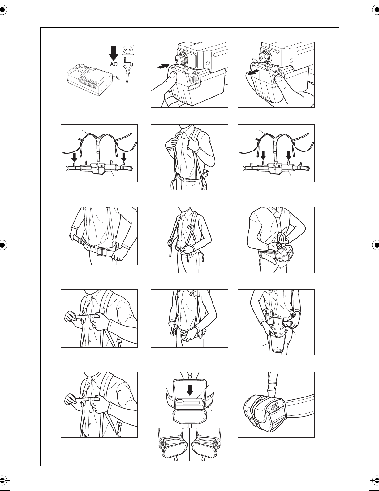
Fig.N/Abb.N Fig.O/Abb.O Fig.P/Abb.P
15
Fig.Q/Abb.Q Fig.R/Abb.R Fig.S/Abb.S
26
26
27
Fig.T/Abb.T Fig.U/Abb.U Fig.V/Abb.V
Fig.W/Abb.W Fig.X/Abb.X Fig.Y/Abb.Y
27
Fig.Z/Abb.Z Fig.AA/Abb.AA Fig.AB/Abb.AB
28
27
34
29
30
RL
4
Page 5

Fig.AC/Abb.AC Fig.AD/Abb.AD
Fig.AE/Abb.AE
Fig.AF/Abb.AF
Fig.AI/Abb.AI
33
10
9
29
10
26
3231
Fig.AG/Abb.AG Fig.AH/Abb.AH
11
Fig.AJ/Abb.AJ
Fig.AK/Abb.AK
10
12
3
6
5
4
Fig.AL/Abb.AL Fig.AM/Abb.AM
34
Fig.AN/Abb.AN
a bb
6
5
5
Page 6
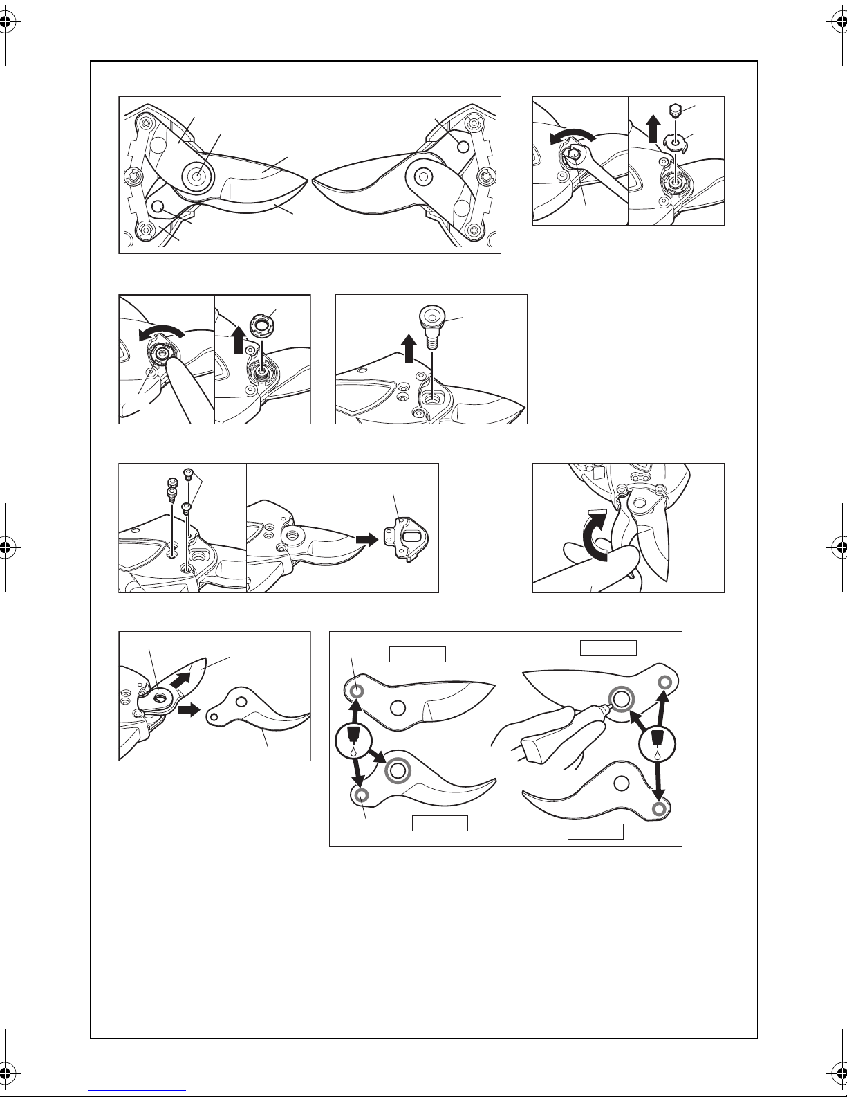
Fig.AO/Abb.AO
Fig.AP/Abb.AP
35
36
39
1
37
2
40
38
Fig.AQ/Abb.AQ
Fig.AR/Abb.AR
42
36
42
Fig.AS/Abb.AS Fig.AT/Abb.AT
43
44
40
41
Fig.AU/Abb.AU
35
Fig.AV/Abb.AV
1
45
1
1’
2
46
2
2’
6
Page 7
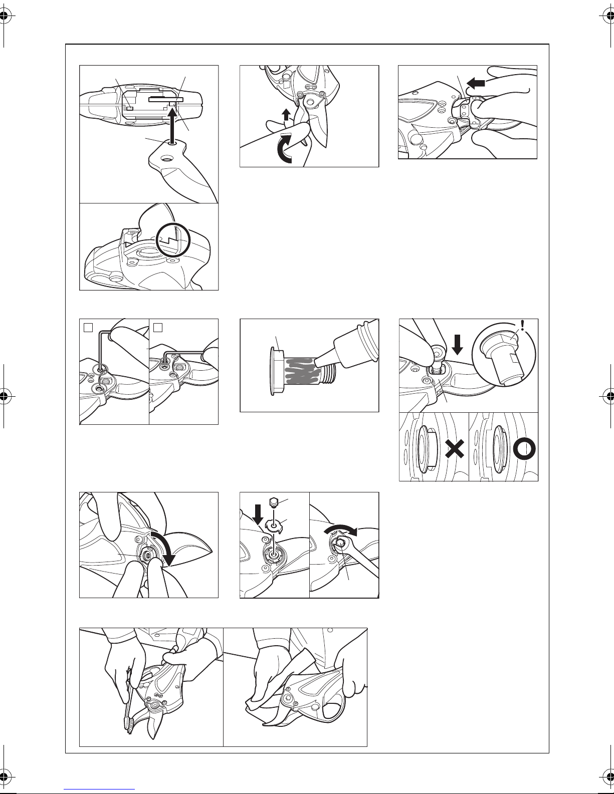
Fig.AW/Abb.AW Fig.AX/Abb.AX
Fig.AY/Abb.AY
37
45
Fig.AZ/Abb.AZ
C D
35
39
Fig.BA/Abb.BA
36
44
Fig.BB/Abb.BB
Fig.BC/Abb.BC
42
Fig.BE/Abb.BE
44
Fig.BD/Abb.BD
40
41
40
7
Page 8
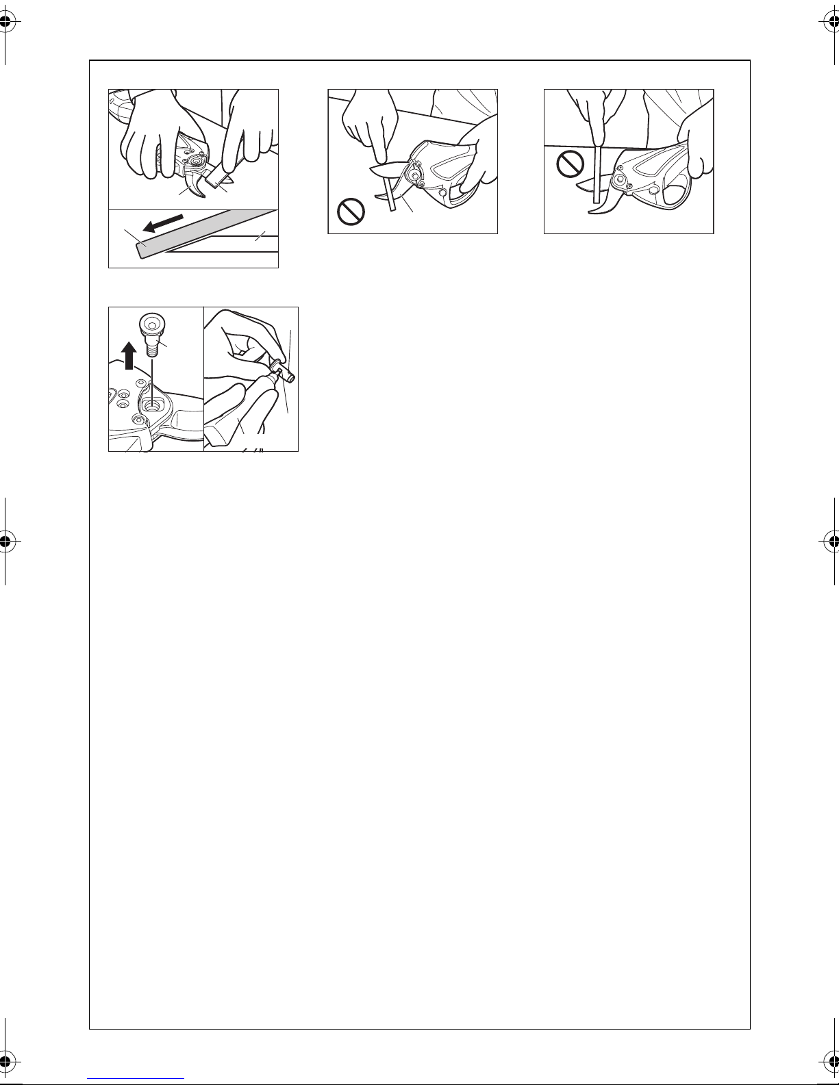
Fig.BF/Abb.BF
Fig.BG/Abb.BG Fig.BH/Abb.BH
1
47
Fig.BI/Abb.BI
36
47
49
1
2
36
48
8
Page 9
ENGLISH
OPERATING AND MAINTENANCE MANUAL
INDEX
1. GENERAL POWER TOOL SAFETY WARNINGS.............9
2. PRUNING SHEARS SAFETY WARNINGS .....................12
3. SPECIFICATIONS AND TECHNICAL DATA ..................14
4. CHARGING METHOD ......................................................17
5. PREPARATION FOR USE ...............................................20
6. HOW TO REPLACE BLADES ......................................... 23
7. MAINTENANCE PROCEDURE........................................24
8. HOW TO READ CONTROL BOX AND SHEAR LAMPS .. 26
9. SIMPLIFIED OPERATION CHART ..................................28
1. GENERAL POWER TOOL
SAFETY WARNINGS
WARNING
READ ALL SAFETY WARNINGS AND ALL
INSTRUCTIONS.
Failure to follow the warnings and instructions
may result in electric shock, fire and/or serious injury. Save all warnings and instruc-
tions for future reference. The term "power
tool" in the warnings refers to your mains-operated (corded) power tool or battery-operated (cordless) power tool.
1. WORK AREA SAFETY
• Keep work area clean and well lit. Clut-
tered or dark areas invite accidents.
• Do not operate power tools in explosive
atmospheres, such as in the presence
of flammable liquids, gases or dust.
Power tools create sparks which may ignite the dust or fumes.
• Keep children and bystanders away
while operating a power tool. Distrac-
tions can cause you to lose control.
2. ELECTRICAL SAFETY
• Power tool plugs must match the outlet.
Never modify the plug in any way. Do
not use any adapter plugs with earthed
(grounded) power tools. Unmodified
plugs and matching outlets will reduce risk
of electric shock.
• Avoid body contact with earthed or
grounded surfaces, such as pipes, radiators, ranges and refrigerators. There is
an increased risk of electric shock if your
body is earthed or grounded.
• Do not expose power tools to rain or
wet conditions. Water entering a power
tool will increase the risk of electric shock.
9
Page 10

• Do not abuse the cord. Never use the
cord for carrying, pulling or unplugging
the power tool. Keep cord away from
heat, oil, sharp edges and moving
parts. Damaged or entangled cords in-
crease the risk of electric shock.
•
When operating a power tool outdoors,
use an extension cord suitable for outdoor use.
Use of a cord suitable for outdoor
use reduces the risk of electric shock.
• Do not use the power tool in the rain,
where water is splashing, in a wet
place, or in a damp place. Using the tool
in these or similar conditions will increase
the risk of electric shock, dangerous malfunction, and overheating. If operating a
power tool in a damp location is unavoidable, use a residual current device
(RCD) protected supply. Use of an RCD
reduces the risk of electric shock.
3. PERSONAL SAFETY
•
Stay alert, watch what you are doing and
use common sense when operating a
power tool. Do not use a power tool while
you are tired or under the influence of
drugs, alcohol or medication.
A moment of
inattention while operating power tools may
result in serious personal injury.
• Use personal protective equipment.
Always wear eye protection. Protective
equipment such as dust mask, non-skid
safety shoes, hard hat, or hearing protection, hand protector used for appropriate
conditions will reduce personal injuries.
• Prevent unintentional starting. Ensure
the switch is in the off-position before
connecting to power source and/or battery pack, picking up or carrying the
tool. Carrying power tools with your finger
on the switch or energizing power tools
that have the switch on invites accidents.
• Remove any adjusting key or wrench
before turning the power tool on.
A wrench or a key left attached to a rotating part of the power tool may result in a
personal injury.
• Do not overreach. Keep proper footing
and balance at all times. This enables
better control of the power tool in unexpected situations.
• Dress properly. Do not wear loose
clothing or jewellery. Keep your hair,
clothing and gloves away from moving
parts. Loose clothes, jewellery or long hair
can be caught in moving parts.
• If devices are provided for the connection of dust extraction and collection facilities, ensure these are connected and
properly used. Use of dust collection can
reduce dust-related hazards.
4. POWER TOOL USE AND CARE
• Do not force the power tool. Use the
correct power tool for your application.
The correct power tool will do the job better
and safer at the rate for which it was designed.
• Do not use the power tool if the switch
does not turn it on and off. Any power
tool that cannot be controlled with the
switch is dangerous and must be repaired.
• Disconnect the plug from the power
source and/or the battery pack from the
power tool before making any adjustments, changing accessories, or storing power tools. Such preventive safety
measures reduce the risk of starting the
power tool accidentally.
• Store idle power tools out of the reach
of children and do not allow persons
unfamiliar with the power tool or these
instructions to operate the power tool.
Power tools are dangerous in the hands of
untrained users.
10
Page 11

• Maintain power tools. Check for misalignment or binding of moving parts,
breakage of parts and any other condition that may affect the power tool's operation. If damaged, have the power
tool repaired before use. Many accidents
are caused by poorly maintained power
tools.
• Keep cutting tools sharp and clean.
Properly maintained cutting tools with
sharp cutting edges are less likely to bind
and are easier to control.
• Use the power tool, accessories and
tool bits etc. in accordance with these
instructions, taking into account the
working conditions and the work to be
performed. Use of the power tool for oper-
ations different from those intended could
result in a hazardous situation.
5. BATTERY TOOL USE AND CARE
• DO NOT DISPOSE OF BATTERY
PACKS/BATTERIES INTO FIRE OR WATER. Battery packs/batteries should be
collected, recycled or disposed of in an environmental-friendly manner.
• PROTECT THE BATTERY AGAINST
HEAT, ALSO AGAINST CONTINUOUS
SUN IRRADIATION AND FIRE. There is
danger of explosion.
•
DO NOT DISPOSE OF POWER TOOLS
INTO HOUSEHOLD WASTE.
According to
the European Guideline 2002/96/EC for
Waste Electrical and Electronic Equipment
and its implementation into national right,
power tools that are no longer usable must
be collected separately and disposed of in
an environmentally correct manner.
• The MAX battery pack uses a Li-ion battery, it may be illegal to dispose of this battery into the municipal waste system.
Check with your local solid waste officials
for details in your area for recycling options
or proper disposal.
• Recharge only with the charger specified by the manufacturer. A charger that
is suitable for one type of battery pack may
create a risk of fire when used with another
type of battery pack.
• Use power tools only with specifically
designated battery packs. Use of any
other battery packs may create a risk of injury and fire.
• When battery pack is not in use, keep it
away from other metal objects, like paper clips, coins, keys, nails, screws or
other small metal objects, that can
make a connection from one terminal to
another. Shorting the battery terminals to-
gether may cause burns or a fire.
• Under abusive conditions, liquid may
be ejected from the battery; avoid contact. If contact accidentally occurs,
flush with water. If liquid contacts eyes,
additionally seek medical help. Liquid
ejected from the battery may cause irritation or burns.
• CHARGE THE BATTERY PACK IN A
TEMPERATURE RANGE 5°C (41°F) TO
40°C (104°F)
6. SERVICE
11
•
Have your power tool serviced by a qualified repair person using only identical replacement parts.
This will ensure that the
safety of the power tool is maintained.
Page 12

2. PRUNING SHEARS SAFETY WARNINGS
1. BE SURE TO KEEP HANDS AWAY FROM
THE TRIGGER SWITCH AND DETACH
THE BATTERY PACK WHEN REPLACING
OR ADJUSTING THE BLADES, WHEN
ABNORMALITIES OCCUR, AND WHEN
THE EQUIPMENT IS NOT BEING USED
Leaving the Battery pack installed in these
situations may cause breakdowns or damage.
2. HOLD TOOL BY INSULATED GRIPS
WHEN PERFORMING AN OPERATION,
BECAUSE THE TOOL'S BLADES MAY
CONTACT HIDDEN "LIVE" WIRE
Contacting with a "live" wire may make exposed metal parts of the tool "electrified" and
shock the operator. Failure to do so may result in serious injury.
3. DO NOT POINT THE TOOL AT ANYONE
Personal injury may result if the tool catches
an operator or anyone working near him.
While working with the tool, be extremely
careful not to bring hands, legs, and other
body parts near the Blades of the tool.
4. NEVER MODIFY THE TOOL
Modifying the tool will impair performance
and operating safety. Any modification may
lead to serious injury and void the tool warranty.
5. THIS APPLIANCE IS NOT INTENDED FOR
USE BY PERSONS (INCLUDING CHILDREN) WITH REDUCED PHYSICAL, SENSORY OR MENTAL CAPABILITIES, OR
LACK OF EXPERIENCE AND KNOWLEDGE,UNLESS THEY HAVE BEEN GIVEN
SUPERVISION OR INSTRUCTION CONCERNING USE OF THE APPLIANCE BY A
PERSON RESPONSIBLE FOR THEIR
SAFETY.
Children should be supervised to ensure that
they do not play with the appliance.
6. MINORS SHOULD NEVER BE ALLOWED
TO OPERATE THE TOOL; IT SHOULD
NEVER BE LEFT UNATTENDED AND
WHEN NOT IN USE SHOULD BE STORED
IN A LOCKED PLACE OUT OF THE
REACH OF CHILDREN.
8. DON’T LEAVE THE MACHINE IN RAIN OR
WET LOCATIONS.
9. KEEP BYSTANDERS WELL AWAY FROM
YOUR WORK AREA.
10. BE CAREFUL NOT TO CATCH FOREIGN
MATTER BETWEEN THE BLADES.
If the blades are jammed with foreign matter,
immediately switch off the machine.
Then remove the foreign matter from the
blades.
11. TAKE CARE, AVOID CUTTING ELECTRICAL WIRES THAT MAY BE HIDDEN.
12. KEEP HANDS AWAY FROM MOVING
PARTS
13. KEEP YOUR FREE HAND AWAY FROM
THE CUTTING AREA.
Never touch the blades. They are very sharp
and you may cut yourself.
14. BE VIGILANT WHEN OPERATING TO ENSURE THAT THE FINGERS ON THE
HAND USED TO HOLD OR MOVE TWIGS
TO BE PRUNED ARE NOT EXPOSED TO
THE CUTTING BLADE.
15. USE ONLY THE AUTHORIZED BATTERY
PACK
Use only MAX JPL925 battery pack. If the
tool is connected to a power supply other
than the authorized pack, such as a rechargeable battery, a dry cell, or a storage
battery for use in automobiles, the tool may
be damaged, break down, overheat, or even
catch on fire. Do not connect this tool to any
power supply except the MAX JPL925 battery pack.
16. TO ENSURE MAXIMUM PERFORMANCE,
FULLY CHARGE THE BATTERY BEFORE
USE
A new battery pack or one not used for extended periods may have self-discharged
and thus may need recharging to restore it to
a fully charged condition. Before operating
the tool, make sure to charge the Battery
pack with the designated MAX Battery
charger JC928.
7. DON’T USE THE MACHINE OR PERFORM
BATTERY CHARGING OPERATIONS IN
THE RAIN.
12
Page 13

17. BATTERY CHARGING PRECAUTION
• Use only MAX Battery charger JC928
and Battery Pack JPL925.
Failure to do so may cause the Battery to
overheat or catch fire leading to serious injury.
• Charge the Battery from AC between
100V and 240V wall sockets.
Failure to do so may result in overheating,
or inadequate charging possibly causing
serious injury.
• Never use a transformer.
• Never connect the Battery charger to an
engine generator direct-current power
supply.
The charger will break down or be damaged from burning.
• Avoid charging the Battery pack in the
rain, in a damp place, or where water is
splashing.
Charging a damp or wet Battery pack will
cause an electric shock or a short circuit
that may lead to damage from burning and
even the tool catching on fire.
• Do not touch the power cord or plug
with a wet hand or glove.
This may cause injury from electric shock.
• Do not put a cloth or any other cover on
the Battery charger while the Battery
pack is being charged.
This will cause overheating and damage
from burning, or the Charger may even
catch fire.
• Keep the Battery pack and Battery
charger away from heat and flames.
• Do not charge the Battery pack near
flammable materials.
• Charge the Battery pack in a well venti-
lated place.
Avoid charging the Battery pack where it
will be in direct sunlight.
•
Charge the Battery pack in a temperature range of 5°C (41°F) to 40°C (104°F).
• Avoid continual use of the Battery
charger.
Rest the Charger for 15 minutes between
charges to avoid functional trouble with the
unit.
• Any objects that block the ventilation
holes or Battery pack receptacle may
cause electric shock or functional troubles.
Operate the charger free of dust or other
foreign materials.
• Handle the power cord carefully.
Do not carry the Battery charger by its
power cord. Do not use the power cord to
disconnect it from a wall socket; this will
damage the cord and break the wires or
cause a short circuit. Do not let the power
cord contact sharp edged tools, hot materials, oil, or grease. A damaged cord must
be repaired or replaced.
• Do not charge non rechargeable batteries with this charger.
• This charger is not intended for use by
children or disabled persons without
supervisor.
• Children should be supervised to ensure that they do not play with the
charger.
• Put a pack cap on the terminal of the
Battery pack.
When the Battery pack is not in use, put a
pack cap on its terminal to prevent short
circuits.
Keep it away from other metal objects,
such as clips, coins, keys, nails, screws or
other small metal objects, that can make a
connection from one terminal to another.
• Do not leave or store the tool in a vehicle or in direct sunlight during summer.
Leaving the tool in high temperature
conditions may cause the battery pack
to deteriorate.
• Do not store a fully discharged battery
pack. If a fully discharged battery pack
is removed from the system and left for
a long period of time, it may become
damaged. Recharge the battery immediately when it has been discharged.
13
Page 14

3. SPECIFICATIONS AND TECHNICAL DATA
1. NAME OF PARTS(SEE Fig.A-BI)
1 UPPER BLADE
2 LOWER BLADE
3LED LAMP
4 TRIGGER LOCK LEVER
Fig.A
Fig.B
Fig.C 12 CABLE TERMINAL
Fig.D
Fig.E
5 TRIGGER
6 SWITCH LEVER
7TERMINAL
50
NAME LABEL (SPECIFICATION LABEL)
51 WARNING LABEL
8LED LAMP
9 TERMINAL CAP
10 TERMINAL
11 POWER SWITCH
52 SPECIFICATION/WARNING LABEL
13 BATTERY CAP
14 BATTERY TERMINAL
15 LATCH
16 VENTILATOR SLITS
17 SPECIFICATION / WARNING LABEL
18 BATTERY PACK ENTRY POINT
LED LAMP (RED/GREEN) CHARGING
19
STATUS INDICATOR LAMP
LED LAMP (ORANGE) CHARGING
20
STATUS INDICATOR LAMP
21 SPECIFICATION / WARNING LABEL
22 VENTILATOR SLITS
23 CE(VDE) POWER PLUG
24 POWER CORD
53 WARNING LABEL
Fig.G 25 BATTERY PACK
Fig.Q
Fig.AA
Fig.AD
Fig.AF 33 ARM BAND
Fig.AL 34 HOLSTER
Fig.AO
Fig.AP
Fig.AQ 42 BLADE HOLDER
Fig.AS
Fig.AV
Fig.BF
Fig.BI
26 SUSPENDER
27 WEST BELT
28 WEST PAD
29 CONTROL BOX
30 TERMINAL OF THE CONTROL BOX
31 PROJECTION OF THE TERMINAL
32 CONVEX OF THE TERMINAL
35 BLADE ARM FOR UPPER BLADE
36 SHAFT
37 PIN FOR LOWER BLADE
38 BLADE ARM FOR LOWER BLADE
39 PIN FOR UPPER BLADE
40 BOLT 5X8
41 WASHER
43 BOLT 4X6 (4PCS.)
44 ALUMINUM BASE
45 HOLE
46 HOLE
47 SHARPENER
48 GREASE SUMP
49 GREASE IN TUBE
2. TOOL SPECIFICATION<TOOL>
PRODUCT NO. PASJ30(CE)
WEIGHT 0.9Kg(2.0lb)
HEIGHT 120mm(4-7/8")
WIDTH 50mm(2")
LENGTH 330mm(13-1/8")
RATED VOLTAGE / BATTERY 25.2V, Li-ion Battery pack JPL925
MOTOR Brushless DC Motor
OPERATING TEMPERATURE -10°C to 40°C (14°F to 104°F)
OPERATING HUMIDITY 80% RH or less
MAXIMUM CUTTING CAPACITY 30mm/15mm diameter
14
Page 15

<BATTERY CHARGER>
PRODUCT NAME MAX lithium ion battery charger
PRODUCT CODE JC928(CE)
INPUT AC100-240V 50/60Hz 1.62-0.68A
OUTPUT
WEIGHT 1.6Kg
OPERATING TEMPERATURE RANGE -10°C to 40°C (14°F to 104°F)
OPERATING HUMIDITY 80% RH or less
DC 7.2/10.8/14.4V 7A
DC 18/21.6/25.2/28.8V 3.9A
<BATTERY PACK>
PRODUCT NAME MAX lithium ion battery pack
PRODUCT NO. JPL925
BATTERY TYPE Lithium ion battery
NOMINAL VOLTAGE DC25.2 V
NOMINAL CAPACITY 3.0 Ah (3,000 mAh)
CHARGING TIME
(USE WITH JC928(CE))
ACCESSORIES Pack cap (For preventing short circuit)
WEIGHT 0.9 Kg
CHARGING TEMPERATURE 5°C to 40°C (41°F to 104°F)
OPERATING TEMPERATURE -10°C to 40°C (14°F to 104°F)
OPERATING HUMIDITY 80% RH or less
Quick charging - Approximately 45 minutes (Apprx. 90% of capacity)
Full charging - Approximately 54 minutes at 20°C (100% of capacity)
<CONTROL BOX>
PRODUCT NAME control box for 25.2v battery pack
NOMINAL VOLTAGE DC25.2V
RATED VOLTAGE/BATTERY 25.2V, Li-ion Battery pack JPL925
ACCESSORIES Connector cap (For preventing short circuit)
WEIGHT 0.4Kg/1.3Kg (With Battery)
SIZE (L) × (H) × (W) (L)181mm × (H)129mm × (W)84mm (With Battery)
15
Page 16

3. TECHNICAL DATA
1 NOISE
A-weighted single-event ------ LWA, 74.81 dB
sound power level
A-weighted single event ------ LpA, 63.81 dB
emission sound pressure
level at work station
Uncertainty (K): 3 dB
These values are determined and documented in accordance to EN60745-1.
2 VIBRATION
Vibration characteristic value - 0.0321 m/s
Uncertainty (K): 1.5 m/s
2
2
These values are determined and documented in accordance to EN ISO 5349-1 and EN ISO 5349-2.
This value is a tool-related characteristic value and does not represent the influence to the handarm-system when using the tool. An influence to the hand-arm-system when using the tool will, for
example, depend on the gripping force, the contact pressure force, the working direction, the adjustment of main supply, the workpiece, the workpiece support.
3 RADIATED EMISSION 30-1000 MHZ
Class B
4 Overvoltage category
category I according to IEC 60664-1
5 Pollution degree
degree 4 according to IEC 60664-1
6 Design guidelines
Machinery directive Annex I, EN 60745-1, EN 60745-2-8
EMI :EN 55014-1 RFP EN 61000-6-3 RE
EMS :EN 55014-2 CATEGORY IV EN 61000-4-2/-3/-4/-6
4. ABOUT PRODUCTION YEAR
This product bears production number in the body. The two digits of the number from left indicates
the production year.
(Example)
10826035D
Year 2010
<Standard accessories>
● JPL925 (Battery), 1 piece ● JC928 (Rapid charger), 1 unit
● Control box, 1 unit ● Connection cable, 1 piece
● Battery holder (with holster and arm band), 1 piece ● Hex wrench, 2 piece
● Spanner, 1 piece ● Safety glasses, 1 pair ● Sharpener, 1 piece
● Instruction manual, 1 copy ● Carry case, 1 piece
<Main uses>
● Pruning fruit trees
• Please note that the main functions, shapes and other features in the above specifications are subject
to change for purposes of improvement.
16
Page 17

4. CHARGING METHOD
WARNING
• Charge at the specified voltage.
Be sure to charge using a AC100V - 240V wall
socket. Charging with a other voltage other
than that specified cannot only cause problems but is also dangerous.
• Never charge with an engine generator or a
DC power supply.
This can not only cause a problem but also can
also result in abnormal heating and fire.
• Use a standard wall socket.
The charger must be securely plugged into a
wall socket. The power plug must not be loose
or be able to come out easily. Use of a wall
socket that does not allow the power plug to be
inserted securely may result in an accident
caused by overheating. If that is a possibility,
use another wall socket.
• Keep the pack cap on the battery pack
whenever it is not being used.
∗ Initial state of battery pack
The battery pack is not fully charged when you
purchase it. Correctly charge the battery pack
using the charger before use.
CAUTION
• In its initial state, the battery pack, although
not fully charged, can be used to operate
the machine when it is attached. Be careful
not to operate the trigger switch inadvertently.
• When installing or removing the battery
pack in the control box, check that the power switch of the control box is turned off.
1 (Fig. F) Remove the pack cap, which cov-
ers the battery pack terminal area, used
to prevent short circuiting.
(Fig. G) When the battery pack is used once
and installed in the control box, remove the
pack from the machine first.
(See P 20, How to remove the battery pack.)
2 (Fig. H) Plug the charger power cord into
a AC100V - 240V wall socket.
The red LED lamp blinks and a pip sounds
twice to indicate that the power is on.
3 Charge the battery pack.
(1) (Fig. I) Slide the battery pack firmly until it
reaches the end of the battery pack installation port of the charger.
(2) (Fig. J) If the battery pack is connected to the
charger, charging starts automatically.
The red LED lamp lights up and a pip sounds
once to indicate that the battery is being
charged.
(3) When the battery pack has been rapid-
charged, the red indicator LED lamp will start
to blink green.
(Fig. K) When the green LED lamp blinks, a
beep will sound for approximately two seconds. At this point, the battery has been recharged to approximately 90% capacity.
The rapid charging process takes approximately 45 minutes. (However, the recharging time and capacity will charge slightly
depending on the ambient temperature and
power voltage)
(Fig. L) You can use the battery pack when
rapid charging is complete. However, if you
leave the battery pack on the charger, charging will continue. When the battery is fully
charged (to 100% capacity), the green LED
lamp lights up (and a beep will sound for approximately two seconds).
4 (Fig. M) After you have charged the bat-
tery pack, remove it from the charger.
5 (Fig. N) Unplug the charger power cord
from the wall socket.
17
Page 18

INDICATION OF QUICK CHARGER LAMPS
Charger LED lamp Buzzer sound Recharging status
Red lamp blinks.
It blinks every second.
The power cord is plugged
into the receptacle.
Two short beeps (Pi, pi)
The charger is
powered.
The charger power cord is plugged
into a wall socket.
Red lamp lights.
It remains lit.
The green lamp blinks.
It blinks every second.
The green lamp lights up.
It remains lit.
The red lamp lights up.
The orange lamp lights up.
They remain lit.
The orange lamp lights up.
It remains lit.
The orange lamp blinks.
It blinks quickly (0.1 sec
ON and 0.1 sec OFF).
The battery pack is mounted.
One short beep (Pi)
The battery has been recharged.
A long beep for approx. 2
seconds (Piii...)
Fully recharged.
A long beep for approx. 2
seconds (Piii...)
— Protective charging
— Standby
Not possible to recharge.
Short continuous beeps for
approx. 10 seconds
(Pi, pi, pi, pi,...)
The battery is being recharged.
The battery has
been recharged.
Battery is "fully" recharged.
Not possible to recharge.
Quick recharging continues.
The battery has been recharged to approx. 90% of its capacity.
If you leave the battery pack on the
charger, recharging will continue.
Recharged to 100% capacity.
The battery is recharged with a low
current to protect the charger and battery.
If the temperature of the battery pack
is too high: Battery recharging starts
automatically when the temperature
drops below the limit.
If the temperature of the battery pack
is too low: Place the battery pack in a
room temperature location for a while,
then retry recharging it.
Unable to recharge the battery.
The battery pack slot is contaminated,
or the battery pack has failed.
∗ For batteries those are at low temperatures (10°C (50°F) or lower), charging time must be extended
longer.
18
Page 19

CAUTION
• When the orange LED lamp blinks and short beeps keep sounding for approximately 10 seconds: Charging failed
You cannot charge the battery. If this occurs, first unplug the power cord from the wall socket. Next,
remove the battery pack from the charger, and check whether any foreign substances have entered
the terminals of the battery pack or charger. If any foreign substances are found, remove them using
a soft material.
If no foreign substances are found, or if the orange LED lamp is still blinking even after foreign substances have been removed, the battery pack may have expired, or the battery pack or charger may
be malfunctioning. If you have an extra battery pack, use it. If the orange LED lamp still blinks, return
the battery pack and charger to your dealer for inspection or repair.
• When a fully charged battery pack is set on the charger again, the red LED lamp may light up,
but this is not a failure. The lamp will soon turn green, indicating that the battery is fully
charged.
• The charger has a cooling fan that may start working due to the temperature of the battery pack
and charger. The fan stops working when the temperature drops.
• Certain ambient temperature conditions or the battery pack may prolong the charging time.
• Charging several battery packs continuously may prolong the average charging time.
• Once charging is completed, allow the charger to rest for approximately five minutes before
charging again.
• In the following cases, return the battery pack and charger to your dealer for inspection or repair, since they may be faulty.
− When the power cord is plugged into a AC100V - 240V wall socket, the red LED lamp does not blink.
(with the battery pack not set.)
− When the battery pack is connected to the charger, the red or orange LED lamp does not light or
blink.
− When the battery pack is hot and the orange LED lamp lights up, the red LED lamp does not light up
60 or more minutes have elapsed.
− When the red LED lights up, it does not start blinking green after 90 or more minutes have elapsed.
19
Page 20

5. PREPARATION FOR USE
1. Installing or removing the battery
pack
WARNING
• When installing or removing the battery
pack in the control box, check that the
power switch of the control box is
turned off.
• Make sure that the battery pack is correctly installed in the control box before
use.
An incorrectly installed battery pack may
fall off during operation, which may result in
personal injury.
• Keep the connector cap on the control
box whenever it is not being used.
(Fig. O) To install the battery pack, first align the
slot on the battery pack with the slot on the control box, then slide it in the direction of the arrow
until it clicks securely in place.
(Fig. P) To remove the battery pack from the
control box, press the latches at both sides and
slide the pack straight forward in the direction of
the arrow, while holding the hollow part on the
control box side with your other hand.
2. Preparation for use
1 (Fig.Q Fig.S) Attach the front side of the
suspender to the waist belt.
There are two points on the belt for attaching
the suspender. Choose the one of your liking.
2 (Fig.R) Put your arm through the sus-
pender.
3 (Fig.T) Secure the waist belt, pull it to the
right and left to adjust the length so that
it fits properly.
4 (Fig.U Fig.V) Adjust the length of the sus-
pender belt so that it fits properly.
5 (Fig.W) Secure the chest belt and adjust
the length so that it fits properly.
6 (Fig.X) After adjusting the suspender and
belts, remove the waist belt and chest
belt, and set the battery holder down.
7 Install the battery pack in the control box.
3. Installation method
1 (Fig. AA) Store the control box containing
the battery pack into the battery holder so
that the terminal of the control box is on
the same side as your dominant hand.
Store the control box with the LED lamps
facing upward.
2 (Fig.AB) Firmly fasten the control box
storage section of the battery holder using the buckle.
3 (Fig.AC) Remove the connector cap,
which covers the control box terminal area, used to prevent short circuiting.
4 (Fig.AD) Connect the connecting cable to
the control box terminals and tighten the
screws of the terminals on the connecting cable side.
∗ You can connect either terminal at the
right and left ends of the connecting cable.
∗ The terminal on the control box side
has a projection while the connecting
cable side has a hollow. Connect the
cable so that they will fit with each other.
For a simplified control box chart, see page 26.
5 (Fig.AE) Putting on the battery holder
Hold the bottom of the connecting cable terminal at the unconnected end with the hand
that you will use to hold the shears, taking
care not to touch the inside of the terminal.
Carry the battery holder on your back as you
would carry a rucksack.
(Fig.Y) Fit the holster on the waist belt and
(Fig.Z) buckle the waist belt, suspender and
chest belt.
If you use a purchased waist bag in addition
to the battery holder, adjust the bottom of the
battery holder to the top of the waist bag belt
so that you can easily put on and take off the
battery holder.
∗ Take care that the connecting cable
does not get between your body and
the shoulder band of the battery pack.
6 (Fig.AF) Putting on the arm band
Put the arm band on your upper arm as
shown in the figure, and fix the connecting
cable.
7 (Fig.AG) Connecting the machine and
connecting cable
Insert the connecting cable terminal into the
machine terminal and turn it to the right to
connect it securely.
20
Page 21

∗ Similarly to when connecting the con-
trol box, match the hollow and projection of the connecting cable and
machine.
4. Switch operation
CAUTION
Before connecting the control box
• Check that you cannot pull the trigger
unless you depress the switch lever.
• Check that the trigger returns when you
depress the switch lever and pull and release the trigger.
If the switch lever or trigger does not operate correctly, it could result in an accident.
1 (Fig.AH) Turn on the power switch of the
control box.
∗ When the switch is turned on
The red LED lamp of the shears slowly
blinks.
Check that the machine is standing by and
that the green LED lamp blinks slowly.
At this time, one to three of the green LED
lamps on the top of the control box light up.
− The three green LED lamps indicate the
battery charge level. If all of the three
LED lamps are lit up, the battery is
charged sufficiently. If only one green
LED lamp is blinking, charge the battery.
• If the red LED lamp of the shears lights up
There is a problem. Check the cause of the
problem by inspecting the LED lamps on the
control box.
− If one or more red LED lamps lights up or
blinks, there is a problem. The cause of the
problem can be checked by inspecting the
lighting and blinking patterns of the red LED
lamps. For an explanation of the patterns,
see "HOW TO READ CONTROL BOX AND
SHEAR LAMPS" on p 26.
2 (Fig.AI) Release the trigger lock lever of
the shears.
• When the blades are closed
While depressing the trigger and switch lever, push the trigger lock lever in the direction of the arrow to release the lock.
• When the blades are open
Push the trigger lock lever in the direction
of the arrow to release the lock.
3 (Fig.AJ) Hold down the switch lever of the
shears.
If the switch lever is depressed, the buzzer
sounds for a short time. If the switch lever is
not released, the buzzer sounds for a long
time. When the blades open and the blinking
green LED lamp of the shears lights up, the
machine is ready.
If the blades do not open, release the switch
lever, and then hold it down again.
∗ If you depress the trigger, the blades do
not open. Hold down the switch lever
with the trigger released.
∗ If the green LED lamp of the shears
blinks quickly, the battery is not
charged sufficiently. Charge the battery.
4 (Fig.AK) If the trigger is pulled ( ) with
the switch lever depressed, the blades
move in the closing directions. If the trigger is not released, the blades stop at the
closed positions.
If the trigger is released ( ), the blade
moves in the direction of the opening and
stops at the fully open positions.
The blades open and close according to the
extent the trigger is pulled.
5. How to switch the opening angle
of the blades
This machine can cut twigs of diameters up
to 30 mm, but you can change the maximum
diameter to 15 mm by switching the opening
angle of the blades.
1 (Fig.AJ) Press the switch lever twice and
then release it.
2 Hold the switch lever with the trigger
pulled for two seconds until the buzzer
sounds.
∗ Do steps 1 and 2 within five seconds of
each other.
3 If the buzzer does not sound, release the
switch lever and the trigger. One second
later, repeat steps 1 and 2.
Every time you do the operations above, the
maximum diameter changes from 30 mm to 15
mm and vice-versa.
• When it is unnecessary to switch the open-
ing angle of the blades
1 Press the switch lever five times.
2 Disconnect the connection cable from
the shears.
21
Page 22

3 When the buzzer sounds from the control
box, turn off the power.
4 Operate the switch as explained in "4.
Switch operation" on page 21. After that,
the opening angle of the blades cannot
be switched over.
∗ If you need to switching the opening angle
of blades, perform steps 1 to 4 again.
6. How to store the shears in the holster
(Fig. AL) Turn off the power switch of the
control box while pulling the trigger (with the
blades closed)
∗ While the blades are closed, check that the
lamp of the shears is turned off.
WARNING
• When storing the shears in the holster,
be sure to close its blades.
If the machine is stored while its blades are
open, you may be injured and the holster
may be broken.
∗ If the trigger lock lever is locked with the
trigger pulled (with the blades closed),
the blades are kept closed even if the
trigger is released after that.
To open the blades again, release the
trigger lock lever while depressing the
trigger and switch lever.
7. Pruning method
WARNING
• Use safety glasses.
Wear safety glasses when using the machine. Otherwise you run the risk of eye
damage due to flying chips.
(Fig. AM) When pruning, cut twigs one by one
between the upper and lower blades.
(This machine can cut twigs with a diameter of
up to approximately 30 mm. When the opening
angle of the blades is changed, the diameter can
be up to about 15 mm.)
∗ If the battery charge level is low, the ma-
chine may not be able to cut twigs.
∗ The machine may not be able to cut twigs,
depending on the dryness of the wood or
other factors.
When stopping work, lock the trigger lock lever
with the blades closed or turn off the power
switch of the control box, and then store the
shears in the holster.
∗ If the machine is not used for five minutes,
it is set in the standby mode automatically.
When starting work again, release the trigger lock lever. Then, hold down the switch
lever. After the buzzer sounds, you can restart pruning work.
∗ If the machine is not used for 60 minutes,
the power is turned off automatically.
∗ When starting the work again, turn the
switch off, and then turn it on again. Then,
hold down the switch lever. After the buzzer sounds, you can re-start pruning work.
When you have finished pruning, turn off the
power of the control box with the blades closed,
disconnect the connecting cable, remove the
battery pack from the control box, fit the pack cap
to the battery pack, and store the machine in a
dry location that is not affected by high temperature and that is away from children.
22
Page 23

MOTOR PROTECTION FUNCTION
This machine has a circuit that stops the machine when the motor becomes hot.
If the motor stops, stop using the machine, turn
off the power switch, wait until the motor cools
down, and then start the work again.
• Notification that the machine stopped because of motor high temperature
The buzzer sounds and the two at both ends of
the three lamps on the control box blink in red
and the center one goes off.
6. HOW TO REPLACE BLADES
WARNING
• When replacing the blades, be sure to
turn off the power switch of the control
box with the blades open, and disconnect the connecting cable from both the
control box and the machine.
• When replacing the blades, be sure to
wear gloves.
CAUTION
• Avoid using the machine in a way in
which the motor protection function operates on a frequent basis.
This can cause the motor to heat up or experience other problem.
8. If a twig is caught in blades
If a twig is caught in the blades (cannot be cut by
the cutting action), release the trigger. Releasing
the trigger moves the blades in the opening direction.
If the twig is still caught in the blades after releasing the trigger, do not move the machine to the
sides but move it slowly in up and down with the
trigger released to free the twig from the blades.
To reuse the machine after removing the twig,
release the switch lever again. After that, the machine can be used as normal.
WARNING
• If the blades break and scatter, workers
may sustain injuries that lead to loss of
eyesight or other serious injuries.
(Fig.AN) Do not move the blades in a lateral direction since the trigger may break and
the blades may be crushed.
a: Correct usage method
b: Lateral movement during the cutting ac-
tion that can break the blades
[STRUCTURE AROUND SHAFT] (FIG.
AO)
1. How to remove blades
1 (Fig.AP) Loosen the hex bolt with the at-
tached hex spanner to remove the hex
bolt and washer.
2 (Fig.AQ) Use your hand to rotate the
blade holder in the direction of the arrow
and remove it.
3 (Fig.AR) Reverse the machine and pull
out the shaft.
4 (Fig.AS) Remove the four hex socket
head bolts with the attached hex wrench
to remove the aluminum base.
∗ When removing the bolts, take care not
to injure your hand on the blades.
5 (Fig.AT)Move the lower blade to the left
as shown in the figure, turn it clockwise
and remove it from the pin of the blade
arm for lower blade.
∗ Be sure to wear gloves when removing
the lower blade. Touching blade with
bare hands may cause injury.
6 (Fig.AU) Pull out the lower blade. Move
the upper blade into the space after the
lower blade is pulled out and pull out the
upper blade.
2. How to install blades
1 (Fig.AV) Apply grease to the upper and
lower blades.
2 (Fig.AW) Insert the hole of the upper
blade to the pin of the blade arm for the
upper blade.
23
Page 24

3 (Fig.AX)Insert the lower blade into the
shears. Turn the lower blade clockwise
as inserted into the shears and insert the
hole on the lower blade over the pin of the
blade arm for lower blade.
4 After inserting the upper and lower
blades over the pins of the blade arms,
pull the upper and lower blades, and confirm that they do not detach.
∗ If the blades detach, they are not insert-
ed over the pins of the blade arms properly. In such a case, reinsert them.
5 (Fig.AY) Insert the aluminum base be-
tween the blade and the machine and adjust the hole for the hex socket head bolt.
∗ If the blades are open too wide, the alu-
minum base floats and cannot be installed.
6 (Fig.AZ) Tighten the four hex socket head
bolts using the attached hex wrench.
∗ Tighten bolt "a" holding the short end
of the L-wrench, and tighten bolt "b"
holding the long end of the wrench.
(To stabilize the tightening force)
7 (Fig.BA) Apply the attached grease all
around the shaft.
8 (Fig. BB) Insert the shaft in the shaft hole.
Insert the shaft so that its flat face will be
matched with the hole of the aluminum
base.
∗ If it is difficult to insert the shaft, swing
the lower blade in both vertical and lateral directions.
9 (Fig.BC) While holding the shaft to pre-
vent it from coming out, install the blade
holder by rotating it with your hand.
∗ Tighten the blade holder firmly until
you cannot rotate it any more without
using a tool.
0 (Fig.BD) Install the washer and be sure to
tighten the hex bolt using the attached
wrench.
7. MAINTENANCE PROCEDURE
WARNING
• When inspecting or servicing, be sure to
turn off the switch of the control box and
disconnect the connecting cable from the
machine.
If you inspect or service the machine with the
connecting cable connected, an unexpected
accident may occur.
1 How to maintain blades
(Fig.BE) After working, remove dirt from both
sides of the blades using a hard brush and wipe
them with wet cloth for storage.
If the blades are not maintained, the friction of
the blades will increase and the usage time after
one charge is shortened.
The lives of the blades will also be shortened.
2 How to sharpen blades
(Fig.BF) How to sharpen upper blade
Match the flat side of the grindstone to the angle
of the blade edge, press it in the direction of the
arrow and sharpen the entire blade edge.
CAUTION
• (Fig.BG) Do not sharpen the lower
blade.
CAUTION
• (Fig.BH) Do not sharpen the reverse
side of the blade.
After carrying out the above process, connect
the machine to the control box and check its operation.
If the upper and lower blades are operating correctly, the replacement work is completed.
If the blades do not operate correctly, remove
and install them again according to the procedure in "HOW TO REPLACE BLADES" (P 23). If
the machine still does not operate correctly, return it to your dealer for inspection or repair.
3 How to apply grease
Apply grease to the shaft at the rate of once
a month or so.
(Fig.BI) Apply the grease evenly to the shaft
and grease sump.
For information about how to remove the
shaft, see "HOW TO REPLACE BLADES",
Step 1 and 2 (P 23).
24
Page 25

4 Cautions when not using the machine for
long periods
When not using the machine for long periods, remove the battery pack from the control box and charge it fully. Fit the pack cap
to the battery pack, and store the machine in
a dry location where it will not be affected by
high temperatures.
The battery pack will discharge even if it is
not used, although at a very slow rate. If the
battery is kept at a low charge level for a long
period, it will become unusable.
Even if you do not use the machine for a long
period, charge the battery once every six
months or so.
5 Never modify or carry out repair work on
this machine
If this machine is modified, it will not operate
optimally and may become a safety risk.
Therefore, do not modify it under any circumstances.
6 Periodic inspection of the machine
To maintain the machine's performance, carry out cleaning and inspection.
25
Page 26

8. HOW TO READ CONTROL BOX AND SHEAR LAMPS
[LAMP ON THE CONTROL BOX]
Normal state (Lamp is green)
Lamp alternately
Normal (Green)
State of lamp
: Lit up
: Blinking
: OFF
Contents of
display
Remedy
Battery charge
level is full
Use the machine.
If the battery charge level is low, the machine may not be
able to cut twigs.
Battery charge
level is medium
If an error or problem occurs (Lamp is red)
Battery charge
level is low
Battery needs to
be charged
Charge the battery.
blinks between red
and green
Maintenance period
Return the tool to your
dealer for repair.
State of lamp
: Lit up
: Blinking
: OFF
Contents of
display
Remedy
Error (Blinking red)
Battery pack
charge level is low
Stop using the
machine, charge
the battery, then
start the operation
again.
Motor temperature is high
Stop using the
machine, wait until the motor cools
down, then start
the operation
again.
Blades were locked
during cutting action
Release the trigger
and switch lever. If the
twig is still caught in
the blades, open the
blades, taking care
not to swing the machine laterally.
No power is supplied
to the machine
Turn off the power,
and turn it on again after confirming the connection of the
connecting cable terminals. If the display
does not disappear,
the machine has a
problem.
Circuit trouble
If the red lamp lights
up (remains on), turn
the power on again. If
the red lamp still lights
up after that, stop using the machine and
consult your dealer.
Problem
(Light up red)
26
Page 27

[LAMP ON THE SHEARS]
Normal state (Lamp is green)
Normal (Green)
State of lamp
: Lit up
: Blinking
: OFF
Contents of display Standby Battery needs to be charged
If the machine is not used for five min-
Remedy
utes, it is set in the standby mode.
When using again, hold down the
switch lever.
If an error or problem occurs (Lamp is red)
State of lamp
: Lit up
: Blinking
: OFF
Contents of display Error No power is supplied
Check the contents of the error with
Remedy
the control box.
Slow blinking Quick blinking
Charge the battery.
Error (Red) Lamp off
Check the power supply of the control
box and the connecting cable to ensure there is a secure connection and
no breakage.
Lamp alternately blinks between
red and green
Maintenance period
Return the tool to your dealer for repair.
• Maintenance period
The machine counts the number of times that the blades lock under strong load.
This count is used to notify users that it is time for maintenance.
Servicing may be needed even if maintenance is not indicated on the machine.
27
Page 28

9. SIMPLIFIED OPERATION CHART
Turn on the power switch.
The buzzer makes a "pip" sound.
The shears do not operate. (They
are in the standby mode.)
Depress the switch lever.
The buzzer makes a "pip" sound.
If you keep depressing (holding
down) the switch lever, the buzzer
makes a "peep" sound and the
blades open.
* If the trigger lock lever has been
applied with the trigger pulled, release the lock to open blades.
∗ LED indicates when the battery is
fully charged.
Shears LED
The green LED
starts slowly blinking.
Shears LED
The Green LED
stops blinking and
stays light.
Control box LED
The green LED
lights up.
Control box LED
The green LED
lights up.
Start the work again
Turn off the power
switch once.
Start the work again
Pull/release the trigger while depressing the switch lever.
The blades move according to the
operation of the trigger.
If the trigger is pulled, the blades
close. If the trigger is released, the
Shears LED
The green LED
lights up.
blades open.
Do not operate the trigger for five minutes.
The buzzer makes a "peep" sound.
Then, the blades do not move even
if the trigger is pulled.
(The machine is returned to the
standby mode.)
Shears LED
The green LED
starts slowly blinking.
Do not operate the trigger for 60 minutes.
The buzzer makes a "peep" sound.
Then, the blades do not move even
if the trigger is pulled. (The power is
turned off.)
Shears LED
The green LED
stops blinking slowly and turns OFF.
Control box LED
The green LED
lights up.
Control box LED
The green LED
lights up.
Control box LED
OFF
28
 Loading...