

Page 1
NF565/16
16 GA. FINISH NAILER
16. CLOUEUR DE FINITION A ANGLE DE 16 Ga
CLAVADORA DE ACABADO ANGULAR DE CALIBRE 16
OPERATING AND MAINTENANCE MANUAL
MANUEL D'UTILISATION ET D'ENTRETIEN
MANUAL DE OPERACIONES Y MAN T ENIMIENTO
BEFORE USING THIS TOOL, STUDY THIS MANUAL TO ENSURE SAFETY WARNING AND INSTRUCTIONS.
KEEP THESE INSTRUCTIONS WITH THE TOOL FOR FUTURE REFERENCE.
WARNING
AVANT D’UTILISER CET OUTIL, LIRE CE MANUEL ET LES CONSIGNES DE SÉCURITÉ AFIN DE
GARANTIR UN FONCTIONNEMENT SÛR.
CONSERVER CE MANUEL EN LIEU SÛR AVEC L’OUTIL AFIN DE POUVOIR LE CONSULTER UL-
AVERTISSEMENT
ADVERTENCIA
TÉRIEUREMENT.
ANTES DE UTILIZAR ESTA HERRAMIENTA, LEA DETENIDAMENTE ESTE MANUAL PARA FAMILIARIZARSE CON
LAS ADVERTENCIAS E INSTRUCCIONES DE SEGURIDAD.
CONSERVE ESTAS INSTRUCCIONES JUNTO CON LA HERRAMIENTA PARA FUTURAS CONSULTAS.
Page 2

INDEX INDEX ÍNDICE
ENGLISH Page 3 to 11
FRANÇAIS Page 12 to 20
ESPAÑOL Page 21 to 29
DEFINITIONS OF SIGNAL WORDS
WARNING: Indicates a potentially hazardous situation which, if not avoided, could result in
death or serious injury.
CAUTION: Indicates a potentially hazardous situation which, if not avoided, may result in mi-
nor or moderate injury.
NOTE: Emphasizes essential information.
DÉFINITIONS DES DIFFÉRENTS DEGRÉS D’ AVERTISSEMENTS
AVERTISSEMENT: I ndique une situation éventuellement dangereuse qui, si elle n’est pas
contournée, pourrait provoquer la mort ou des blessure sérieuses.
ATTENTION:
REMARQUE: Souligne des informations importantes.
DEFINICIÓN DE LAS INDICACIONES DE ADVERTENCIA
ADVERTENCIA: Indica una situación potencialmente peligrosa que podría causar la muerte o
PRECAUCIÓN: Indica una situación potencialmente peligrosa que podría causar lesiones menos
NOTA: Resalta informaciones importantes.
Indique une situation éventuellement dangereuse qui, si elle n’est pas contournée,
pourrait provoquer des blessures légères à moyennement sérieuses.
graves lesiones si no se evita.
graves o leves si no se evita.
2
Page 3
ENGLISH
OPERATING AND MAINTENANCE MANUAL
INDEX
1. GENERAL SAFETY WARNINGS........................................................3
2. SAFETY WARNING.............................................................................4
3. SPECIFICATIONS AND TECHNICAL DATA......................................7
4. AIR SUPPLY AND CONNECTIONS....................................................8
5. INSTRUCTIONS FOR OPERATION................................. .. .. ...............8
6. MAINTENANCE .................................................................................11
7. STORAGE..........................................................................................11
8. TROUBLE SHOOTING/REPAIRS.....................................................11
BEFORE USING THIS TOOL, STUDY THIS MANUAL TO ENSURE SAFETY WARNING AND INSTRUCTIONS.
KEEP THESE INSTRUCTIONS WITH THE TOOL FOR FUTURE REFERENCE.
WARNING
1. GENERAL SAFETY WARNINGS
WARNING
READ ALL SAFETY WARNINGS AND ALL
INSTRUCTIONS.
Failure to follow the warnings and instructions
may result in death serious injury.
ings and instructions for future re fere nce.
Save all warn-
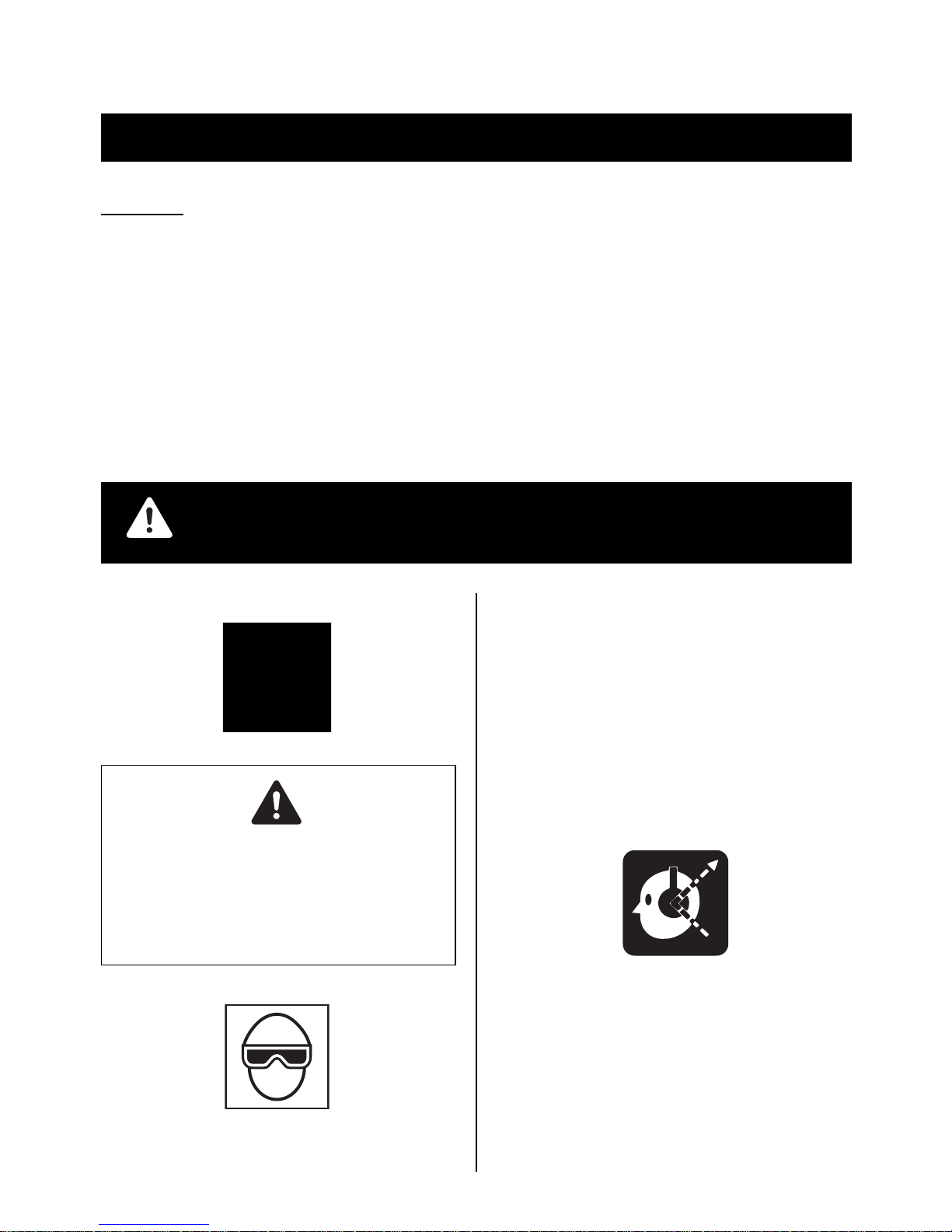
1. WEAR SAFETY GLASSES OR GOGGLES
Danger to the eyes always exists due to the possibility of
dust being blown up by the exhausted air or of a fastener flying up due to the improper handling of the tool. For these
reasons, safety glasses or goggles shall always be worn
when operating the tool.
The employer and/or user must ensure that proper eye pr otection is worn. Eye protection equipment must conform to
the requirements of the American National Standards Institute, ANSI Z87.1 (Council Directive 89/686/EE C of 21 DEC.
1989) and provide both frontal and side protection.
The employer is responsible to enforce the use of eye protection equipment by the tool operator and all other perso nnel in the work area.
NOTE: Non-side shielded spectacles and face shields
alone do not provide adequate protection.
2. EAR PROTECTION MAY BE REQUIRED IN SOME ENVIRONMENTS
As the working condition may include exposure to high noise
levels which can lead to hearing damage, the employer and
user should ensure that any necessary hearing protection is
provided and used by the operator and others in the work area.
3
Page 4

3. KEEP HANDS AND BODY AWAY FROM THE DISCHARGE OUTLET
When loading and using th e tool, never place a han d or any
part of body in fastener discharge area of the tool. It is very
dangerous to hit the hands or body by mistake.
4. DO NOT USE ON SCAFFOLDINGS AND LADDERS
Do not use on scaffoldings and ladders wit h fastener driving
tools equipped with contact actuat ion or continuo us contact
actuation.
2. SAFETY WARNING
Thinner
Gasoline
3. DO NOT OPERATE THE TOOL NEAR A FLAMMABLE
SUBSTANCE
Never operate the tool near a flammable substance (e.g.,
thinner, gasoline, etc.). V olatile fume s from the se substances could be drawn into the compressor and com pressed together with the air and this could result in an explosion.
4. NEVER USE THE TOOL IN AN EXPLOSIVE ATMOSPHERE
Sparks from the tool may ignite atmospheric gases, dust or
other combustible materials.
5. DO NOT USE A WRONG FITTINGS
The connector on the tool must not hold pressure when air
supply is disconnected. If a wrong fitting is used, the tool
can remain charged with air after disconnecting and thus
will be able to drive a fastener even after the air line is disconnected, possibly causing injury.
1. DO NOT USE ANY POWER SOURCE EXCEPT AN AIR
COMPRESSOR
The tool is designed to operate on compressed air. Do not
operate the tool on any other highpressure gas, combustible gases (e.g., oxygen, acetylene, etc.) since there is the
danger of an explosion. For this reason, absolutely do not
use anything other than an air compressor to operate the
tool.
2. O PERATE WITHIN THE PROPER AIR PRESSURE
RANGE
The tool is designed to opera te within an ai r pressure range
of 70 to 100 p.s.i. (5 to 7 bar).
The pressure should be adjusted t o the type of the wo rk being fastened. The tool shal l never be operated wh en the operating pressure exceeds 120 p.s.i. (8.3 bar).
Never connect the tool to air pressure which potentially exceeds 200 p.s.i. (13.8 bar) as the tool can burst.
6. DISCONNECT THE AIR SUPPLY AND EMPTY THE
MAGAZINE WHEN THE TOOL IS NOT IN USE
Always disconnect the air supply from the tool and empty
the magazine when operation has been completed or suspended, when unattend ed, moving to a diffe rent work are a,
adjusting, disassembling, or repairing the tool, and when
clearing a jammed fastener.
7. INSPECT SCREW TIGHTNESS
Loose or improperly installed screws or bolts cause accidents and tool damage when the tool is put into operation.
Inspect to confirm that all screws and bolts are tight and
properly installed prior to operating the tool.
4
Page 5

8. DO NOT TOUCH THE TRIGGER UNLESS YOU INTEND
TO DRIVE A FASTENER
Whenever the air supply is connected to the tool, never
touch the trigger unless you intend to drive a fastener into
the work. It is dangerous to walk around carrying the tool
with the trigger pulled, and this and similar actions should
be avoided.
9. NEVER POINT THE DISCHARGE OUTLET TOWARD
YOURSELF AND OTHER PERSONNEL
If the discharge outlet is pointed toward peopl e, serious accidents may be caused when misfiring. Be sure the discharge outlet is not pointed toward peopl e when connecting
and disconnecting the hose, loadin g and u nloadi ng the fasteners or similar operations.
10. USE SPECIFIED FASTENERS
(SEE PAGE 7)
The use of fasteners other than specified fasteners will
cause the tool malfunction. Be sure to use only specified
fasteners when operating the tool.
13. DO NOT DRIVE FASTENERS ON TOP OF OTHER FASTENERS
Driving fasteners on the top of other fasteners may cause
deflection fasteners which could cause injury.
14. REMOVING THE F ASTENERS AFTER COMPLETING
OPERATION
If fasteners are left in the magazine after the completion of
operation, there is the danger of a serious accident occurring prior to the resu mptio n of o peration, should the tool be
handled carelessly, or when connecting the air fitting. For
this reason, always remove all fasteners remaining in the
magazine after completion of the operation.
15. CHECK OPERATION OF THE CONTACT TRIP MECHANISM FREQUENTLY INCASE OF USING A CONTACT
TRIP TYPETOOL
Do not use the tool if the trip is not working correctly as accidental driving of a fastener may result. Do not interfere
with the proper operation of the contact trip mechanism.
16. WHEN USING THE TOOL OUTSIDE OR ELEVATED
PLACE
When fastening roofs or similar slanted surface, start fastening at the lower part and gradually work your way up.
Fastening backward is dangerous as you may lose your foot
place.
Secure the hose at a point close to the area you are going
to drive fasteners. Accidents may be caused due to the
hose being pulled inadvertently or getting caught.
11. PLACE THE DISCHARGE OUTLET ON THE WORK SURFACE PROPERLY
Failure to place the discharge outle t of the nose in a proper
manner can result in a fastener flying up and is extremely
dangerous.
12. DO NOT DRIVE FASTENERS CLOSE TO THE EDGE
AND CORNER OF THE WORK AND THIN MATERIAL
The workpiece is likely to split and the fa stener could fly free
and hit someone.
17. NEVER USE THE TOOL IF ANY PORTION OF THE TOOL
CONTROLS (e.g., TRIGGER, CONTACT ARM) IS INOPERABLE, DISCONNECTED, ALTERED OR NOT WOKING PROPERLY
18. NEVER ACTUATE THE TOOL INTO FREE SPACE
This will avoid any hazard caused by free flying fasteners
and excessive strain of the tool.
19. ALWAYS ASSUME THAT THE TOOL CONTAINS FASTENERS
20. RESPECT THE TOOL AS A WORKING IMPLEMENT
21. NO HORSEPLAY
22. NEVER LOAD TH E TOOL WITH FASTENERS WHEN
ANY ONE OF THE OPERATING CONTROLS (e.g., TRIGGER, CONTACT ARM) IS ACTIVATED
5
Page 6

23. WHEN DISPOSING THE MACHINE OR ITS PARTS, FOLLOW THE RELEVANT NATIONAL RULES
OBSERVE THE FOLLOWING GENERAL CAUTION IN ADDITION TO THE OTHER WARNINGS
CONTAINED IN THIS MANUAL
• Do not use the tool as a hammer.
• Always carry the tool by the grip, never carry the
tool by the air hose.
• The tool mus t be use d only for t he purpo se it was
designed.
• Never remove, t amper with the operat ing controls
(e.g., TRIGGER, CONTACT ARM)
• Keep the tool in a dry place out of reach of chil-
dren when not in use.
• Do not use the tool without Safety Warning label.
• Do not modify the tool from original design or
function without approval by MAX CO., LTD.
6
Page 7

3. SPECIFICATIONS AND TECHNI-
CAL DATA
1. NAME OF PARTS
3
2
1
5
9
2. TOOL SPECIFICATIONS
PRODUCT NO. NF565/16
HEIGHT 11-3/16" (284 mm)
WIDTH 3-3/4" (95 mm)
LENGTH 11-11/16" (297 mm)
WEIGHT 3.4 lbs (1.5 kg)
RECOMMENDED
OPERATING PRESSURE
LOADING CAPACITY 110 Nails
AIR CONSUMPTION 0.045 ft3 at 100 p.s.i.
∗ The machine has been compactly designed in order to im-
prove operating weight balance.
3. BRAD NAIL SPECIFICATIONS
7
6
4 8
(1.3 at 7 bar)
operating pressure
1 Frame
2 Cylinder Cap
3 Exhaust Port
4 Magazine
5 Pusher Lock
Button
6 Trigger
7 Grip
8 Warning Label
9 Outlet
70 to 100 p.s.i.
(5 to 7 bar)
TOOL AIR FITTINGS:
This tool uses a 1/4" N.P.T. male plug. The inside diameter
should be .28" (7mm) or larger. The fi tting must be cap able of discharging tool air pressur e when disconne cted from the air supply.
RECOMMENDED OPERATING PRESSURE:
70 to 100 p.s.i. (5 to 7 bar ). Select the ope rating air pressur e within this range for best fastener performance.
DO NOT EX C E E D 1 20 p.s .i. (8 .3 ba r ).
4. TECHNICAL DATA
1 NOISE
A-weighted single-event sound power level
NF565/16------ LWA, 92.3 dB
A-weighted single-event emission sound pressure level at
work station
NF565/16------ LpA, 84.2 dB
These values are determined and documente d in accordance to EN12549 : 1999.
2 VIBRATION
Vibration characteristic value
= 3.5 m/s
These values are determined and documente d in accordance with ISO 8662-11.
This value is a tool -related characteristi c value and does n ot
represent the influence to the han d-arm-system when using
the tool. An influence to the hand-arm-system when using
the tool will, for example, depend on the gripping force, the
contact pressure force, the working direction, the adjustment of mains supply, the workpiece, the workpiece support.
2
Wire gauge: 16
<1.4 mm>
5. APPLICATIONS
∗ Door and window casings
∗ Plywood, decorative boards, and other interior finish works
∗ Panel assembly and moldings
∗ Sub flooring
∗ Furniture assembly including drawer assembly, case back
nailing, blind pinning, and other finishing works
∗ Cabinet assembly
7
Page 8

4. AIR SUPPLY AND CONNECTIONS
WARNING
[AIR SUPPLY & CONNECTIONS]
Air compressor
Air hose
5
70
7
Air filter
100
Used at 70 to 100 p.s.i. (5 to 7 bar)
Regulator
Oiler
3-piece airset
5. INSTRUCTIONS FOR OPERATION
Read section titled "GENERAL SAFETY WARNINGS","SAFETY WARNING"
1. BEFORE OPERATION
Check the following prior operation.
1 Wear Safety Glasses or Goggles.
2 Do not connect the air supply.
3 Inspect screw tightness.
4 Check operation of the contact arm & trigger if moving
smoothly.
5 Connect the air supply.
6 Check the air-leakage. (The Tool must not have the air-
leakage.)
7 Hold the Tool with finger-off the trigger, then push the con-
tact arm against the work-piece. (The tool must not operate.)
8 Hol d the Tool with con tact arm free from work-piece and pull
the trigger. (The Tool must not operate.)
9 Disconnect the air supply.
WARNING
FITTINGS: Install a male plug on the tool which is free flowing
and which will release air pressure from the tool when disconnected from the supply source.
HOSES: Hose has a min. ID of 1/4" (6 mm) and max. length of
no more than 17" (5 meters).
The supply hose should contain a fitting that will provide "quick
disconnecting" from the male plug on the tool.
SUPPLY SOURCE: Use only clean regulated comp ressed air as
a power source for the tool.
3-PIECE AIRSET (Air filter, Regulator, Oiler):
Refer to TOOL SPECIFICATIONS for setting the correct operating pressure for the tool.
NOTE:
A filter will help to get the best performance and minimum wear
from the tool because dirt and water in the air supply are major
causes of wear in the tool.
Frequent, but not excessive, lubrication is required for the best
performance. Oil added thru the air li ne conne ction wi ll lubr icate
the internal parts.
2. OPERATION
Wear safety glasses or goggles. Danger to the eyes always exists due to the possibility of dust being blown up by the exhausted
air or of a fastener flying up due to the improper handling of the
tool. For these reasons, safety glasses or goggles shall always
be worn when operating the tool.
The employer and/or user must ensure that pr oper eye protecti on
is worn. Eye protection equipment must conform to the requirements of Council Directive 89/686/EEC of 21 DEC. 1989 (the
American National Standards Insti tute, ANSI Z87 .1) and provide
both frontal and side protection.
The employer is responsible to enforce the u se of eye protecti on
equipment by the t ool operator and all other per sonnel in the wor k
area.
NOTE: Non-side shielded spectacles and face shields alone do
not provide adequate protection.
WARNING
Keep hands and body away from the disch arge outlet when driv ing the fasteners because of dangerous of hitting the hands or
body by mistake.
8
Page 9

NAIL LOADING
TEST OPERATION
1 Adjust the air pressure at 70 p.s.i. (5 bar) and connect the
air supply.
2 Without touching the trigger, depress the contact arm
against the work-piece.
Pull the trigger (The tool must fire the fastener.)
3 With the tool off the work-piece, pull the trigger.
Then depress the connect arm a gainst the work-piece . (The
tool must fire the fastener.)
4
Adjust the air pressure as much as the lowest possible according the length of fastener and the hardnes s of work piece.
AIR HOSE CON NECTION
Connect the air chuck to the air plug.
1 Pull pusher back into "locked" position
Pusher
2 Insert the finish nails into the magazine
Finish nails
WARNING
When connecting the air chuck, do not point the nail discharge outlet at any part of your body or at another person,
and do not touch the trigger.
DRIVING FASTENERS
NOTE :
This tool is shipped with SEQUENTIAL TRIP selected.
SEQUENTIAL TRIP
The Sequential Trip requires the operator hold the tool against
the work before pulling the trigger.
This makes accurate fastener placement easier, for instance on
framing, toe nailing and crating applications.
The Sequential Trip allows exact fastener location without the possibility of driving a se c on d fastener on recoil, as described under
"Contact Trip".
The Sequential Trip Tool has a positive safely advantage because it will not accidentally d ri ve a fasten er if the to ol is cont acted against the work or anything else-w hile the oper ator is ho lding
the trigger pulled.
Switching SEQUENTIAL TRIP to CONTACT TRIP
WARNING
ALWAYS-disconnect air supply before switching the triggering method.
3 Push the pusher lock button and put back the pusher.
Button
1 Press the button on the trigger.
9
Page 10

Switching lever
2 Turn the switching lever in the direction of the arrow.
DRIVING DEPTH ADJUSTMENT DIAL
Adjustment dial
WARNING
ALWAYS-disconnect air supply before adjusting adjustment
dial.
Switching lever
3 Set the switching lever as above picture.
CONTACT TRIP
The common operating procedure on "Contact Trip" tools is for
the operator to contact the work to actuate the trip mechanism
while keeping the trigger pull ed, thus drivi ng a fastener each time
the work is contacted.
All pneumatic tools are subject to recoil when driving fasteners.
The tool may bounce, releasing the trip, and if unintentionally allowed to recontact the work surface with the trigger still actua ted
(finger still holding trigger pulled) an unwanted second fastener
will be driven.
1 If an adjustment is required, disconnect air supply.
2 Refer to the figure for direction to turn the dial.
3 Reconnect air supply.
THE CONTACT TIP
Contact tip
Contact tip
WARNING
ALWAYS-disconnect air supply before setting the contact tip.
Set the contact tip on the top of the contact arm, when driving
nails to a s o ft m a te rial.
Contact arm
Use the contact tip at the back of the rear side of the magazine
as necessary.
Trigger
10
Page 11

CLEARING JAM M ED NAI LS
Latch Cover
6. MAINTENANCE
1 ABOUT PRODUCTION YEAR
This product bears production number at the lower part of
the grip of the main body. The two digits of the number fr om
left indicates the production year.
Driver
Guide A
WARNING
ALWAYS-disconnect air supply before clearing jammed nails.
1 Disconnect the air hose.
2 Remove the set of nails from the magazine.
3 Open the Latch Cover, then pu ll up to open the Driver Guide
A.
4 Clear the nails-jammed inside the driver guide using a thin
iron bar or a flat-blade screw driver.
5 Close the Driver Guide A and the Latch Cover.
(Example)
0 8 8 2 6 0 3 5 D
Year 2008
2 DO NOT FIRE THE NAILER WHEN IT IS EMPTY
3 USE A 3-PIECE AIRSET
Failure to use a 3-piece airset allows the moisture and dirt
inside compressor to pass into the tool directly. This causes
rust and wear, and results in a po or operatin g performance.
The hose length between airset and tool should be no longer than 5 m since a longer length results in a reductio n in air
pressure.
4 USE RECOMMENDED OIL
The velocite or turbine oil should be used to lubricate the
tool. Upon completion of operations, place 2 or 3 drops of
oil into the air plug inlet with the jet oiler. (Recommended Oil
: ISO VG32)
5 INSPECT AND MAINTAIN DAILY OR BEFORE OPERA-
TION
WARNING
Disconnect air supply and empty the magazine when inspecting or maintaining the tool.
(1) Drain air line filter and compressor
(2) Keep lubricator filled in air 3-pieces set
(3) Clean filter element of air 3-pieces set
(4) Tighten all screws
7. STORAGE
1 When not in use for an extended period, a pply a thin coat of
the lubricant to the steel parts to avoid rust.
2 Do not store the tool in a cold weather environment. Keep
the tool in a warm area.
3 When not in use, the tool should be stored in a warm and
dry place. Keep out of reach of children.
4 All quality tools will eventually require servicing or replace-
ment of parts because of wear from the normal use.
8. TROUBLE SHOOTING/REPAIRS
The troubleshooting and/or repairs shall be carried out only by
the MAX CO., LTD. authorised distributors or by other specialists.
11
Page 12

• The content of this manual might be changed without notice for improvement.
• Le contenu de ce manuel est sujet a modification sans preavis a des fins d'amelioration.
• El contenido de este manual puede ser cambiado sin noticia previa para mejoramiento.
• The specifications and design of the product s i n th is m anual will be subject to ch ange without
advance notice due to our continuous ef f or ts to impr ove the quality of our pro ducts.
• Les caracterist iq ues et la conception des produits mention nes dans ce manuel sont sujettes a
des modifications sans preavis en raison de nos efforts continus pour ameliorer la qualite de nos
produits.
• Las caracteristicas y la concepcion de los productos mencionados en este manual estan sujetas
a modificaciones sin preaviso debido a nuestros esfuerzos continuos para mejorar la calidad de
nuestros productos.
www.maxusacorp.com (USA Site)
wis.max- ltd . co .jp /i n t/ (G LO BAL Site )
257 East 2nd Street
Mineola, NY 11501, U.S.A.
TEL: 1-800-223-4293
FAX: (516)741-3272
4009538
111019-00/00
 Loading...