

Page 1
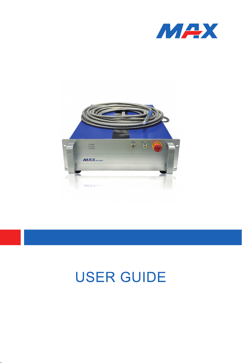
MFSC 500W-1000W CW Fiber Laser Series
Maxphotonics Co.,Ltd.
Page 2

Page 3

Copyright Notation
Copyright © Maxphotonics Co., Ltd (hereafter referred to as
Maxphotonics). All rights reserved. You may not copy, modify, transmit or
publish this publication, in any form, in any media or by any means, without
the prior written permission of Maxphotonics, except as allowed under
applicable copyright laws. Permitted copies shall bear the same copyright
and proprietary notices that were contained on the original version.
All information contained in this document is subject to change
and revision without notice. Maxphotonics believes that the information
provided is accurate and reliable; however Maxphotonics makes no
warranty, representation, expression or implication that this document can
be used as reference in other occasions. Furthermore, Maxphotonics does
not assume responsibility for any infringement of patents or other rights
of third parties due to use of the information contained in this document.
Maxphotonics shall not be liable for errors contained in this document or
for direct or indirect damages of relevant equipment.
Maxphotonics grants no rights for patent or other intellectual property
mentioned herein.
Maxphotonics and the Maxphotonics Logo are registered trademarks
of Maxphotonics Co., Ltd., and the Logo does not break any regulations of
Trademark law.
Page 4

Preface
Thank you for using the MFSC 500W-1000W Series fiber laser
products. We compile this document for you in order that the laser is used
and maintained properly. Due to the limited level of the writers, coupled
with time constraints, there are some careless mistakes in this document,
and your understanding will be much appreciated. Thank you again for
using Maxphotonics' products.
Please take time to read and understand this User’s Guide and
familiarize yourself with the operating and maintenance instructions before
you use the product. We recommend that the operator read the Section
titled “Safety Information” prior to operating the product.
This User’s Guide should stay with the product to provide you and
all future users and owners of the product with important operating, safety
and other information.
We identify the parts to which you need to pay special attention in the
document with underscore. Please notice those information to prevent the
unnecessary damages.
Page 5

Company Profile
As a large laser manufacturer founded in 2004, Maxphotonics
Co., Ltd. specializes in research and development, production and
sales of lasers and ancillary products. Maxphotonics owns a number of
independent intellectual property rights and patents as well as high-power
pulsed fiber laser, high-power fiber laser and high-power fiber amplifier
etc.
So far, with intellectual property rights and patents, Maxphotonics
owns industrial pulsed fiber laser series, fiber laser for scientific
researches, tunable fiber laser, fiber amplifier, ASE light source, etc.
Those products are widely applied to fields of laser marking, DTS system
and scientific research.
3
Maxphotonics offers laser, relevant solution and ancillary facility to
domestic and foreign customers. We adhere to the enterprise mission
statement of ''Maxphotonics leads the industry'', take customer satisfaction
as the start point, completely implement ISO9001 quality management
system, introduce ERP information management system and provide all-
round pre-sales and after-sales service for customers.
Relying on excellent ability of product design and development, we
carry out all-round exchanges and cooperation with international famous
laser companies and various research institutions of China, continuously
increase the investment of science research, constantly update
diversification of production types, lead the trend of the industry and create
maximum value for customers, so as to strive perseveringly for the world-
class laser manufactures and forge ahead.
Page 6

Contents
4
Company Profile ……………………………………………………………… 3
Chapter 1 Characteristic Explain ……………………………………… 6
Chapter 2 General Safety Information ……………………………… 7
1-Safety Conventions ………………………………………………………… 7
2-Laser Protection …………………………………………………………… 8
3-Reference Standard ……………………………………………………… 9
4-General Safety Instructions ……………………………………………… 10
5-Additional Safety Information …………………………………………… 15
Chapter 3 Product Description ………………………………………… 16
1-Property Introductions …………………………………………………… 16
2- Module Configuration …………………………………………………… 16
3-Laser Model Designation Codes ……………………………………… 17
4-Certification ………………………………………………………………… 17
5-Front Panel Description …………………………………………………… 18
6-Back Panel Description …………………………………………………… 18
7-Optical Output Terminal …………………………………………………… 19
Chapter 4 Specification …………………………………………………… 20
1-Optical Characteristic Parameters ……………………………………… 20
2-General Characteristic Parameters …………………………………… 21
3-Water Cooling Condition ………………………………………………… 21
Page 7

Contents
4-Structural Layout …………………………………………………………… 23
Chapter 5 Operating Guidance ………………………………………… 24
1-Disassembly Step ………………………………………………………… 24
2-Packing List ………………………………………………………………… 25
Chapter 6 Operation Guide ……………………………………………… 26
1-Notice ………………………………………………………………………… 26
2-Electrical Power Connection …………………………………………… 26
3-Extension Interface ………………………………………………………… 27
4-Fiber Connector Inspection and Cleaning Guide …………………… 28
5-Start Step …………………………………………………………………… 32
5
6-Mode Description …………………………………………………………… 32
7-Software Description ……………………………………………………… 33
8-Error Listing ………………………………………………………………… 35
Chapter 7 Service and Maintenance ………………………………… 37
1-Maintenance Notes ………………………………………………………… 37
2-Service Statements ………………………………………………………… 38
Chapter 8 Warranty Statements………………………………………… 39
1-General Items ……………………………………………………………… 39
2-Warranty Limitations ……………………………………………………… 39
Page 8

6
Chapter 1
Characteristic Explain
MFSC CW Fiber Laser (MFSC500W-1000W) Series products
provide a wide range of wavelength from 1060nm to 1100nm.The lasers
are water-cooled and maintenance-free and with a wall plug efficiency
of more than 25% and deliver high efficiency, high reliability, and high
performance.
Maxphotonics' MFSC CW Fiber Laser (MFSC500W-1000W) Series
are Class 4 laser products and are designed and tested with safety. By
following this User Guide and applying sound laser safety practices, it will
be a safe and reliable device.
Laser light exhibits unique characteristics that may pose safety
hazards. Therefore, the laser light can’t be normally associated with
other light sources, and all operators and people near the laser must be
aware of these special hazards.
In order to ensure the safe operation and optimal performance of the
product, please follow all warnings and safety instructions in this guide
during process of operation, maintenance and service.
For ensuring the safety of operators, operators are urged not to
open the equipment privately at all times. There are no user serviceable
parts, equipment or assemblies associated with this product. Lasers of
unauthorized disassembly shall not be subject to warranty.
Page 9
Chapter 2
General Safety Information
1 -Safety Conventions
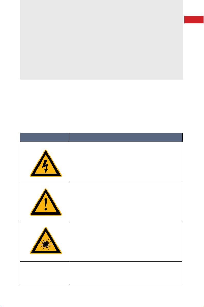
All safety warning symbols during operating process of the laser include:
SYMBOLS DESCRIPTION
WARNING :
Refers to a potential Electrical Hazard to human
body. It requires a procedure that, if not correctly
followed, may result in bodily harm to you and/
or others. Do not proceed beyond the WARNING
sign until you completely understand and meet the
required conditions.
7
NO SYMBOL
CAUTION :
Refers to a potential hazard on product. It requires
a procedure that, if not correctly followed, may result
in damage to the product or components. In order to
ensure normal use of equipment, do not violate the
requirement of the CAUTION sign.
WARNING :
Refers to a potential Laser Hazard.
The symbol represents laser radiation. The symbol is
pasted on laser output end.
IMPORTANT :
Refers to any information regarding the operation of
the product. Please do not overlook this information.
Page 10

Chapter 2 General Safety Information
8
NOTE :
◎ This device is classified as a high power Class IV laser instrument. It
may emit up to 1000W average power from 1060nm to 1100nm. This level
of light may cause damage to the eye and skin. Despite the radiation
being invisible, the beam may cause irreversible damage to the retina.
Laser safety eyewear is not provided with this instrument, but must be
worn at all times while the laser is operational. Use appropriate laser safety
eyewear when operating this device. The manufacturer of the laser system
is responsible for the safety compliance according to the applicable
standards and regulations.
2-Laser Protection
1、Laser Protection Requirements
You must wear the safety protective glasses while operating the laser,
and rationally select the safety protective glasses according to the lasing
wavelength of the laser. If the device is a tunable laser or Raman product,
it emits light over a range of wavelengths and the end user should confirm
the laser safety eyewear used protects against light emitted by the device
over its entire range of wavelength.
2、Laser Protective Equipment Suppliers
Maxphotonics recommends material or equipments provided
by following laser protective equipment suppliers for you, including
LaserVision USA, Kentek Corporation, Rochwell Laser Industries, etc.
All the supplier information is provided by Maxphotonics only for the
convenience to use, so Maxphotonics assumes no responsibility for any
problem caused by using the products of abovementioned suppliers.3-
General Safety Instructions.
Page 11

Chapter 2 General Safety Information
3-Reference Standard
Electromagnetic Compatibility Emission
EN 55011:5009+A1:2010
CISPR 11:5009+A1:2010
FCC Class A
Anti-interference Performance on Electromagnetic Compatibility
EN 61000-3-2:5006+A1:5009+A2:5009
EN 61000-3-3:5008
EN 61326-1:5006
EN 61000-4-2:5009
EN 61000-4-3:5006+A1:5007+A2:2010
EN 61000-4-4:5004+A1:2010
EN 61000-4-5:5006
9
EN 61000-4-6:5009
EN 61000-4-11:204
Others-Electromagnetic Compatibility
Classification A of digital instrument complies with Canada ICES-8003
Power Supply Security
EN 61010-1:5001
Laser Security
EN 60825-1:5007
CDRH 21 CFR 1040.10
Function Security
EN ISO 13849-1:5008+A1:5009 Cat.3 / PL d
Page 12

Chapter 2 General Safety Information
10
Please note :
◎ Performances of Maxphotonics MFSC laser meet the CE EMC
certification requirements, the EMC requirements specified in "EMC
Directive" of European market, the anti-interference requirements
specified in "EMC" standard EN55011 emission and EN61326-1: 8006, and
the emission requirements of group 1 classification A specified in EN55011.
◎ In accordance with relevant national standards and requirements,
the laser must be classified according to its output power and laser
wavelength. All MFSC-800W-Series laser products with high power belong
to Class 4 products (according to section J,1040.10 (d) of Part Ⅱ , 21
CFR).
◎ According to the standards of EU, the equipment belongs to Class 4
instrument (according to article 9, EN 60825-1).
4- General Safety Instructions
1、Specular Reflection
There are often numerous secondary laser beams produced at
various angles in the output port of the laser. These divergent beams are
produced when the primary beam of laser reflects off a smooth surface,
and they are called specular reflections. Although these secondary beams
may be less powerful than the total power emitted from the primary beam,
the intensity may be great enough to cause damage to the eyes and skin
as well as surface of materials.
WARNING:
◎ You must exercise caution to avoid/minimize specular reflections as
these laser radiations are invisible!
2、Safety Instructions of Accessories
Optical accessories relevant to the laser, such as light-sensitive
Page 13

Chapter 2 General Safety Information
elements that may be damaged from exposure to the laser light, video
cameras, photomultipliers and photodiodes, need related protections.
WARNING:
◎ The Maxphotonics MFSC laser light is strong enough to cut or
weld metal, burn skin, clothing and paint. In addition, this light can ignite
volatile substances such as alcohol, gasoline, ether and other solvents.
During the operating process, the flammable materials around the laser
must be isolated.
3、Optical Operating Instructions
We strongly recommend that you read the following procedures before
operating the laser:
(1)Never look directly into the laser output port when the power is
turned on.
(2)Avoid positioning the laser and all optical output components at
eye level.
11
(3)Equip with laser beam casing.
(4)Remove the end-cover before switch ON laser. Or else the
output head will be damaged irreversibly.
(5)Ensure that all personal protective equipment is suitable for the
output power and wavelength range of the laser.
(6)Use the laser in a room with access controlled by door interlocks.
Post warning signs. Limit the safety areas to operate the laser.
(7)Please do not operate laser in darkened environments.
(8)Do not turn on the laser without an optical coupling fiber or the
optical output connector.
(9)Do not install or detach cutting heads or collimators when laser
is active.
Page 14

Chapter 2 General Safety Information
12
(10)Carry out commissioning, calibration and focusing at low output
power and then increase the output power gradually when the calibrating
and focusing work is done.
(11)If the equipment is operated in a manner not specified in this
document, the protection devices and performance of the equipment may
be impaired and the warranty will be voided.
CAUTION :
◎ The output of the laser is delivered through a lens with an anti-
reflection coating. If the backward-stage light path of your laser has the
optical lens, please strictly inspect the lens of the output head and the
backward-stage lens of the laser, and ensure that there is no dust and any
other impurity on the lens. Please note that any macroscopic attachment
may cause extreme damage to lens or burn the laser or any backward-
stage light path equipment.
◎ For cleaning instructions of the lens, please refer to the "Optical
Fiber Connector Inspection and Cleaning Guide".
◎ Hot or molten pieces of metal may be produced when the laser is
under operation. Exercise caution if debris is produced in operation.
◎ When implement commissioning and calibration of laser output,
it’s necessary to set the quality of the spot emitted from the laser at
low power levels via an infrared viewer, and then gradually increase the
output power.
WARNING :
◎ Make sure that the individual protective equipment meets the
output power and wavelength range of the laser.
◎ Never look directly into the optical fiber or the collimator, and
make sure you wear the safety protective glasses in each operation.
Page 15

Chapter 2 General Safety Information
4、Electrical Operating Instructions
We strongly recommend that you read the following procedures before
operating the laser :
(1)Make sure the shell of this equipment is properly grounded. Any
interruption of the ground loop may result in personal injury.
(2)Make sure the power source connecting equipment is properly
grounded.
(3)In order to further reduce fire hazard, replace the line fuses (if
applicable) with the same types and ratings. The use of other fuses or
material is prohibited.
(4)Make sure that the input AC voltage of the laser is the voltage of
the normal AC mains, and wires are connected accurately. Any incorrect
wiring method may cause damage to people or instrument.
(5)The equipment does not have any part which can be maintained
by operators, and all the maintenance operations must be finished by the
professionals of Maxphotonics Co., Ltd.
13
(6)To prevent electrical shock, do not remove enclosure, detach the
laser without permission and damage the relevant signs.
(7)Any product with unauthorized dismounting shall not be subject
to warranty.
WARNING :
◎ The input voltage of the laser is single-phase AC current (220V
AC), which may cause risk of electric shock. All the relevant cables and
connection wires have potential hazards.
Page 16

Chapter 2 General Safety Information
14
5、 Environment conditions and precautions
For ensuring the safety of the laser working area, suitable enclosures
shall be applied, including but not limited the laser safety signs and the
interlocking devices. Corresponding operators must be trained and
examined and know the normal safety specifications for operating the
laser.
Meanwhile, it is important that the output components shall not be
installed at eye level.
Because of interaction of the laser and the metal material, the
radiation of high-level ultraviolet light or visible light may be produced.
Make sure that the laser is provided with the protective cover to prevent
the eyes or other parts of human bodies from damage by radiation.
We recommend that you comply with the following operating
measures to prolong the service life of the laser:
◎ Do not expose the laser to a high moisture/high temperature
environment. Install the laser in the cabinet with the function of
temperature-humidity control and dust-free.
◎ Operation at higher temperature will accelerate aging, increase
threshold current and lower slop efficiency. If the device is overheated,
stop operation and contact Maxphotonics.
CAUTION :
◎ Exercise caution to avoid damage to the device.
◎ If the laser will be in an environment of less than 0 degrees Celsius,
drain all coolant out of laser completely to prevent damage to the laser.
Page 17

Chapter 2 General Safety Information
5-Additional Safety Information
For additional information regarding Laser Safety, please refer to the list
below:
Laser Institute of America(LIA)
13501 Ingenuity Drive, Suite 128
Orlando,Florida 32826
Phone:407 380 1553,Fax: 407 380 5588
Toll Free:1 800 34 LASER
American National Standards Institute
ANSI Z136.1, American National Standard for the Safe Use of Lasers
(Available through LIA)
International Electro-technical Commission
IEC 60825-1,Edition 1.2
15
Center for Devices and Radiological Health
21 CFR 1040.10 - Performance Standards for Light-Emitting Products
US Department of Labor - OSHA
Publication 8-1.7 - Guidelines for Laser Safety and Hazard Assessment.
Laser Safety Equipment
Laurin Publishing
Laser safety equipment and Buyer’s Guides
Page 18

16
Chapter 3
Product Description
1-Property Introductions
As high power lasers developed for industrial application, MFSC
Series lasers are compact and efficient. The lasers are mainly applied to
the fields of welding, cutting, brazing, etc.
Main Features:
(1) High-quality laser output
(2) High power, high efficiency
(3) High reliability, long service life
(4) Compact, rugged package
(5) Extension programming interface
Applications:
(1) Industrial applications
(2) Scientific research
2 - Module Configuration
Maxphotonics offers many configurable modes. This manual will give
complete instructions for all modes, please refer to section 6.3-6.6.
Page 19

Chapter 3 Product Description
3-Laser Model Designation Codes
Model Coding Rules
Model Model Coding Rules
MFSC-500W Maxphotonics Single-mode CW Fiber Laser 500W
MFSC-800W Maxphotonics Single-mode CW Fiber Laser 800W
MFSC-1000W Maxphotonics Single-mode CW Fiber Laser 1000W
4-Certification
Maxphotonics certifies that this equipment has been thoroughly tested
and inspected and meets published specifications prior to shipping. Upon
receiving your equipment, check whether the packaging and accessories
have been damaged in transit. If damage is apparent, please contact
Maxphotonics immediately.
17
Page 20

Chapter 3 Product Description
18
5-Front Panel Description
Front Panel Description
ITEMS FUNCTION DESCRIPTION
(OFF ON) Key Switch Power switch of laser
(Emergency stop)
Emergency Stop Switch
(Start) Start Switch Start laser (on-off signal of hardware)
ALARM Abnormal situation light of laser
ACTIVE Normal situation light of laser
POWER Power light of laser
Emergency stop
6-Back Panel Description
Back Panel Description
Page 21

Chapter 3 Product Description
ITEMS FUNCTION DESCRIPTION
CTRL External control connector
RS232 RS232 connector
AC220 220VAC power input
POWER Leakage protection switch
WATER OUT Water cooling output port
WATER IN Water cooling input port
7-Optical Output Terminal
1 、Optical Output Head
The optical output head come with a protective window that can be
replaced if damaged. Please refer to 6.4 about the cleaning method.
19
Make sure that the black end cap of the QBH head is removed prior to
use and is usually arranged with the laser.
Optical Output Head (QBH head)
Page 22

20
Chapter 4
Specification
1 -Optical Characteristic Parameters
No. Characteristics Test conditions Min. Nom. Max. Unit
1 Operation mode CW/Modulated
2 Polarization Random
Output power 500W
3
Output power 800W
Output power 1000W
Tuning range of output
4
power
5 Emission wavelength 100%CW 1070 1080 1090 nm
6 Spectrum width(3dB) 100%CW 3 4 nm
Short-term power instability
7
8
Long-term power instability 100%CW>24h
9 Beam quality M²
10 Laser switching ON time
11
Laser switching OFF time
12 Modulation rate 100%Output 20 50 KHz
13 Red guide laser power 100%Output 150 μW
Feeding fiber cable
14
length
15 Feeding fiber core size 50(25、30、100 optional) μm
Feeding fiber cable
16
bending radius
17 Output form Standard QBH(LOC)
100%CW 500
100%CW 800
100%CW 1000
10 100 %
100%CW>1h 1 3 %
3 5 %
100%CW
(20u-QBH)
100%CW
(50u-QBH)
10% → 90%Output
90% → 10%Output
MFSC-500W 12 m
MFSC-800W 15 m
MFSC-1000W 15 m
200 mm
50 80 μs
30 50 μs
W
1.3
2.8
Page 23

Chapter 4 Specication
2 -General Characteristic Parameters
No. Characteristics Test conditions Min. Nom. Max. Unit
1 Operating voltage 180 220 240 VAC
Nominal power
consumption
MFSC-500W
Nominal power
2
consumption
MFSC-800W
Nominal
consumption
MFSC-1000W
Operating ambient
3
temperature
Operating ambient
4
relative humidity
5 Cooling method Water-cooling
6 Storage temperature -10 60 ℃
7 Dimensions 750*483*169 mm
8 Weight 65 kg
power
100%Output 2 KW
100%Output 3.2 KW
100%Output 4 KW
10 40 ℃
10 85 %
21
3-Water Cooling Condition
Maxphotonics Version
SN. Characteristics Laser Model Min. Typ. Max. Unit
1 Method Water Cooling
Water
2
Temperature
for laser
Water Flow
3
Rate for laser
cooling
300W-1500W 26 28
2500W-6000W 25 26
300W /500W 10
Flow Rate 12
1500W 15
2500W 30
4000W 42
6000W 65
℃
L/min
Page 24

Chapter 4 Specication
22
300W /500W 21
800W/1000W 30
Minimum head
4
of delivery
Refrigerating
capacity
5
of cooling
machine
Environment
Tem.
10℃ -20
15℃
20℃
25℃ -8.7 0.5 6.2 10.5 13.8 16.7 19.1 21.3 23.2 24.1
30℃ -5.0 4.6 10.5 15.0 18.4 21.4 23.9 26.2 28.2 29.1
40℃ 2.6 12.7 19.1 23.8 27.6 30.7 33.5 35.9 38.0 39.0
50℃ 10.0 20.8 27.6 32.6 36.7 40.0 43.0 45.6 47.9 49.0
10% 20% 30% 40% 50% 60% 70% 80% 90% 95%
-16.4
-12.5
1500W 38
2500W 45
4000W 45
6000W 53
300W /500W 2
800W/1000W
/500W800W/1000W
1500W 3
2500W 4
4000W 5
6000W 8
Dew Point
Maximum relative humidity
-11.9
-6.8 -3.0 0.6 2.6 4.8 7.6 8.4 9.2
-7.9 -2.4 1.5 4.7 7.3 9.6 11.6 13.4 14.2
-3.7 1.9 6.0 9.25 12.0 14.4 16.4 18.3 19.2
Operation Temperature Range
2.5
m
HP
CAUTION :
◎ This chart can be consulted for the dew point (temperature at
which moisture will precipitate or condense out of ambient air) in different
working environment. If the temperature of the laser lower than the
crossing temperature in the chart, there is risk of condensation within the
laser.
Page 25

Chapter 4 Specication
4-Structural Layout
Laser Three Views(Unit:mm)
23
Page 26

24
Chapter 5
Operating Guidance
1 - Disassembly Step
The laser belongs to the precise valuables, so Maxphotonics
recommends the following steps to unpack the packing box.
Please unpack according to the following steps:
(1)Place the packing box containing the laser on a horizontal
platform such as the floor or a large table.
(2)Open the primary box and remove the foam cover.
(3)Since there is fiber on top of the laser, please carefully take it out
from the box and ensure that the maximum bending radius of the optical
armoured cable is greater than 400mm. The fiber shall be taken out under
cooperation of three employees, with two employees lifting the main body
of the laser and another employee taking out the armoured cable.
(4)Remove the form cover and take out the fittings.
(5)Check the fittings according to the ''Packing List''.
(6)Keep all objects after unpacking for future transportation or
storage needs.
Notes :
◎ If any damage of the external package and internal parts has been
found upon receipt of product, please contact Maxphotonics Co., Ltd. or
designated agent immediately.
Page 27

Chapter 5 Operating Guidance
2 -Packing List
Names of fittings Description Unit Quantity
Fiber Laser MFSC(500W-1000W) Piece 1
220VAC power wire 3 M Piece 1
External signal wire 3.5 M Piece 1
25
RS232 signal wire
Power Keys Piece 2
USB disk 16 G Piece 1
Lens cleaning paper Piece 4
Sample of QBH water pipe Ф6x4mm Piece 1
Sample of water pipe of
laser
Manual MFSC User Manual Piece 1
Qualified Report MFSC Testing Report Piece 1
Shielded RS232 cable with
Female head on both ends
Ф12x10mm Piece 1
Piece 1
Page 28

26
Chapter 6
Operation Guide
1 - Notice
Caution :
◎ Please refer to Section "Detail Specification Table" for proper
electrical power.
◎ Refer to Section "General Safety Instructions" for inspecting whether
the configuration environment of peripheral work of the laser meets the
requirements.
2 - Electrical Power Connection
A power input cord of the laser shall be connected to single-phase AC
current. Please make sure the grounding cord is perfectly connected, or
the laser may be damaged potentially.
For ensuring the safety feature, Maxphotonics recommends you
connect a 20A circuit breaker (air switch) in series between the power
supply unit and the laser. This electric power shall be in close proximity to
the power supply unit of the equipment and can be easily disconnected.
Refer to Section "Detail Specification Table" to determine your
electrical specification if you have any problem about wiring.
Page 29

Chapter 6 Operation Guide
3- Extension Interface
For ensuring the communication between the laser and the board
card, Maxphotonics adopts the high-quality HARTING terminal and
provides the CTRL interface connectors. The interface definition is shown
in the figure below.
CTRL Interface Definition
27
CTRL
INTERFACE
PIN
WIRE COLOR
1 Red
2 Red and White
3 Black
4
Black and
white
5 Yellow
6
Black and
yellow
7 Green
8
Green and
white
FUNCTION
DESCRIPTION
Emission enable input
(positive)
Emission enable input
(negative)
Modulation input
(positive)
Modulation input
(negative)
External laser output
(positive)
External laser output
(negative)
DA(0-10V) input
(positive)
DA(0-10V) input
(negative)
REMARK
24VDC high level
voltage valid
24VDC high level
voltage valid
24VDC high level
voltage valid (This
function is same with
auto switch START)
analog signal, control
output power %
Page 30

Chapter 6 Operation Guide
28
9 Brown Fault output 1
10
11 Blue NC
12 Blue and white NC
Emission Enable
Input
Laser Modulation
Input
Power Input
Red Light Signal
Output
Laser Output
Brown and
white
External Control Signal Timing
Fault output 2
Fault output 1 and 2 off
when alarm on
Fault output 1 and 2 on
when alarm off
4-Fiber Connector Inspection and Cleaning Guide
1、工具 Tools
For cleaning a fiber connector you need the following materials:
(1) Powder-free rubber gloves or fingerstall
(2) Lint free optical cleaning wipes and/or swabs
(3)Ahydrous ethanol(Optical level, pure >99.5%)
(4)Compressed air (oil free, water free)
(5)Microscope
(6)Light source
Page 31

Chapter 6 Operation Guide
CAUTION:
◎ It is imperative that the protective lens are checked for dirt, dust, or
damage before you use the fiber connector. It will lead to heavy damage
if the laser equipped with dirty or damaged fiber connector.
◎ The use of a dirty fiber connector can result in laser damage, which
is not covered by the Maxphotonics' warranty.
◎ The laser will not be covered by the Maxphotonics' warranty if the
buyer change the laser without permission.
IMPORTANT
◎ It is imperative that you wear powder-free rubber gloves during
this cleaning procedure! It is hereby stated that damage to the fiber
connector can occur due to mishandling, the use of incorrect cleaning
procedures, or chemicals for cleaning. This is not covered by the
Maxphotonics' warranty.
◎ Ethanol concentration should be above 99.5% during cleaning.
29
2、Operating Procedures
Cleaning and maintaining according to the following procedures:
(1) Switch off the laser power, and place the key switch on position
of ''OFF'';
(2)Remove the black outer protective sleeve and leave the white
inner cap on and clean the fiber connector exterior with optical cleaner,
wipe it with a clean optical wipe and dry it with compressed air.
(3)Place fiber connector in the holder of the microscope, remove
the white inner cap from the connector.
(4)Focus the microscope onto the connector surface so that the
protective lens can be seen clearly from the microscope.
(5)Check the surface carefully. If some contamination is visible on
Page 32

Chapter 6 Operation Guide
30
the surface, cleaning is necessary: 1. Put a few drops of alcohol onto the
lint free swabs and throw away the excessive alcohol. 2. Place the swabs
on the dust via microscope. 3. Cleaning the dust carefully, and move it to
the edge of lens. 4. Repeat these cleaning steps until all contamination is
removed. Take a final check under the microscopy.
(6)Reinstall the inner cap and the outer sleeve onto the cleaned
fiber connector.
(7)Take out the cap and sleeve, then connect the fiber connector
with cutting head quickly and fasten them. (Place the cap face down on a
clean surface or a lint-free wipe.)
Take out the cap and sleeve
Install fiber connector under microscope
Page 33

Chapter 6 Operation Guide
Cleaning protective lens with swabs
IMPORTANT:
◎ Do not reuse a lint-free optical wipe or swab.
◎ Do not touch the protective lens of the fiber connector.
31
◎ Do not blow directly, or else new dirty will be brought.
◎ Do not touch the tip of the cleaning swab with your fingers and use
each swab only once.
◎ Cleaning is necessary before place the protective cover and
sleeve.
◎ Never blow air directly at the surface, because you could imbed
contaminants into the surface. Always blow across the surface !
◎ If the fiber connector could not be installed in optical system
immediately, please cover it with the protective cap cleaned with
compressed air.
Page 34

Chapter 6 Operation Guide
32
5-Start Step
WARNING:
◎ Make sure that all the electrical connections (including cooling
water connections) are connected prior to use. All the connectors must
be held steady with screws if possible.
◎ NEVER look directly into the output fiber and make sure that you
wear the laser safety eyewear while operating the product.
◎ Make sure all power is removed from the laser when wiring.
Starting procedures are as follows:
(1)Start the water-cooling machine;
(2)Remove the end cap of the collimator;
(3)Make sure that the end surface of the collimator is clean and not
covered with impurities;
(4)Make sure that the emergency stop switch is turned on;
(5)Open the power supply of the laser;
(6)Place the key switch of the front panel on position "ON".
(7)Press the START button on the front panel. (For external control
method)
6- Mode Description
The working modes of the laser are as follows:
(1)Internal control: Control the output of the laser via control
software. This mode is used for checking whether the laser is normal or
not, and testing the laser power.
(2)External Control: Control the output of the laser via external
control line (EE, adjustment, 0-10V analog voltage and START button).
The mode is used for cutting and welding.
Page 35

Chapter 6 Operation Guide
7- Software Description
(1)Installment software is saved in USB DISK.
(2)Click right button to unzip the files to D.
33
(3)Double click setup document, finish installment guide.
(4)Double click desktop shortcut to open the program, access to
the following connect interface: Use the serial interface cable which is
enclosed with the device, connect the laser and PC, select a port number,
click “connect” button.
Page 36

Chapter 6 Operation Guide
34
Page 37

Chapter 6 Operation Guide
8-Error Listing
The fault alarm points set by the laser include:
SN. Message Descripion Trouble shooting
35
Front lamp
1
warning
Pump overheat
2
warning
Water cooling
3
plate overheat
fault
Emergency
4
stop alarm
5 Water flow error
Laser internal
light path
testing fault
Overheat fault
of laser
Overheat fault
of water cooling
plate
The emergency
stop switch is
pressed
Pipeline fault of
chiller or laser
Operation leads to low output
power of laser such as low
modulation frequency, low peak
power, low cutting power
For the internal overheat fault of
the laser, please check whether
the pre-set temperature of
water-cooling machine meets
the requirements; if this cause
is excluded, please contact
Maxphotonics.
For overheat fault of water cooling
plate, please check whether the
pre-set temperature of watercooling machine meets the
requirements
Release the emergency stop switch,
the laser will work again after being
restarted; if this fault still exists,
please contact Maxphotonics.
Please check whether the water
pressure is normal,the water
pipeline is clear and replace the
bad water switch if need.
Overcurrent
6
warning
Overcurrent
fault of laser
If ''0-10V'' DA value exceeds
the pre-set value, the internal
overcurrent fault will occur; if the
fault is not caused by this reason,
please contact Maxphotonics.
Page 38

Chapter 6 Operation Guide
36
Overvoltage
7
warning
8
QBH
warning
Overvoltage
fault of laser
Install error of
QBH
If the laser has internal overvoltage,
please check whether the AC
voltage is within the range
of 200~240V.If this cause
is excluded,please contact
Maxphotonics.
The fault will be produced when
QBH head is not inserted in the
internal part of the cutting head;
if this cause is excluded, please
contact Maxphotonics.
Page 39

Chapter 7
Service and Maintenance
1- Maintenance Notes
CAUTION ;
◎ No operator serviceable parts inside. Refer all servicing to qualified
Maxphotonics personnel.
◎ For ensuring that the repairs or replacement within the warranty
scope can be carried out, and perfectly maintaining your interests, please
submit application to the Maxphotonics or the local representative after
finding the faults. Upon receiving our authorization, you need to pack the
product in a suitable package and return it.
37
◎ You should keep the proof when finding any damage after
receiving the product, so as to claim the rights to shippers.
IMPORTANT:
◎ Do not send any product to Maxphotonics without RMA.
◎ If the product is beyond the warranty period or the warranty scope,
customers shall be responsible for the repairing cost.
CHANGE :
◎ We have the rights to change any design or structure of our
product, and the information is subject to change without notice.
Page 40

Chapter 7 Service and Maintenance
38
2-Service Statements
More problems regarding the safety, set-up, operation or maintenance
can be solved by carefully reading this "User Guide". Please call the
Customer Service Department for other questions.
If your problems cannot be solved over the telephone with our
technical support group, you may need to return the product to
Maxphotonics for further troubleshooting.
Page 41

Chapter 8
Warranty Statements
1-General Items
Maxphotonics carries out warranty for any defect of the product
caused by its material and production technology within the warranty
period agreed in contract, and ensures that its product meet the relevant
quality and specification requirements specified in the document under
normal use condition.
Maxphotonics rationally determines to repair or replace the products
with faults caused by its material or production technology within the
warranty period, and repairs or replacement of all the products within the
warranty scope are carried out according to the rest of the warranty period
of primary products.
39
2-Warranty Limitations
Under the following circumstances, the products, parts (including the
fiber connectors) or equipment are not within the warranty scope:
(1) Tampered, opened, detached or reconstructed by personnel
outside Maxphotonics;
(2) Damaged from misuse, neglect or accident;
(3) Used beyond the specification and technical requirements of the
product;
(4) Indirectly damaged from users' software or interfaces;
Page 42

Chapter 8 Warranty Statements
40
(5) Improper installation or maintenance, or operating under conditions
not included in this manual;
(6) The fittings and the fiber connectors are not included in the
warranty scope.
Customers are obligated to understand the information above and
operate according to the User Guide and specification, or the faults arising
therefrom are not included in the warranty scope.
IMPORTANT :
◎ Within the warranty scope, purchasers must feed back within 31
days after finding the product defect.
◎ Maxphotonics does not grant any Third Party rights to repair or
replace the parts, the equipment or other Maxphotonics products.
Page 43

Page 44

Maxphotonics Co.,Ltd.
Address: Maxphotonics Industrial Park, 3rd Furong Road,
Furong Industrial Area, Shajing, Bao’an, Shenzhen, China.518125
E-Mail: info@maxphotonics.com
http://en.maxphotonics.com/
Version 2017 Maxphotonics Co., Ltd.Subject to change without notice.
 Loading...