

Max MB-1000C-NA, MB-1000C-EU Installation Manual
Binding Finisher
MB-1000C-NA
MB-1000C-EU
Installation Procedure
When installing this product, follow these instructions.
(Make sure to perform the actual work with at least 2 people.)
NOTE : THE FINISHER MUST BE INSTALLED BY A CUSTOMER SERVICE REPRESENTATIVE WHO HAS
COMPLETED THE TRAINING COURSES ON THE BASE COPIER AND THE UNIT.
Read this first
1
These Installation Procedure instructions use indications to help you safely perform
installation. The meaning of each indication is explained below.
Indicates a potentially hazardous situation which, if not avoided,
could result in death or serious injury.
Emphasizes essential information.
Indicates a potentially hazardous situation which, if not avoided,
may result in minor or moderate injury.
WARNING
CAUTION
About indications

Ring opener
Rebinding board
Interface cable
Upper side cover
Lower side cover
Slope
Finisher door cover
Tapping screw 3x6
Spanner 24-19
Equipment/Accessories
Equipment/Accessories
No. No.
1
2
3
4
5
6
7
8
9
10
11
12
13
14
15
16
17
18
19
Warranty/Guarantee card (NA only)
DFD docking bracket for upstream
DFD docking bracket for down
Operation manual
+Screw 4×6
Installation procedure
AC power cord
Cartridge label
Cartridge
CD (Operation manual)
1
1
1
1
1
2
1
11
1
1
1
1
1
7
1
1
1
1
1
Checking supplied items
7
11
19
10
1 2
4
6
5
18
9
8
13
16
12
3
17
14
15
2
* This is already installed
in the unit.
20
Safetyinformation
20
1
* NA only

Installation space
The dimensions in the diagram below indicate the minimum amount of space that is
necessary.
300mm
or
more
900mm
or
more
DOWN UP
(860mm)
3
If this unit is the last downstream unit, leave the space indicated below open.
UP
30mm or more

(2) Remove the included items.
(1) Remove the cover of the cardboard box.
Cut the plastic band and remove
the cover of the cardboard box.
(3) Remove the side cover of the cardboard box, and then remove the upper cover of
the cardboard box.
(4) Remove the tape at the top of the plastic cover, and then open and pull down the
plastic cover.
Remove all of the included items.
Remove the side cover of the
cardboard box.
Remove the upper cover of the
cardboard box
Directions for opening the cardboard box
4
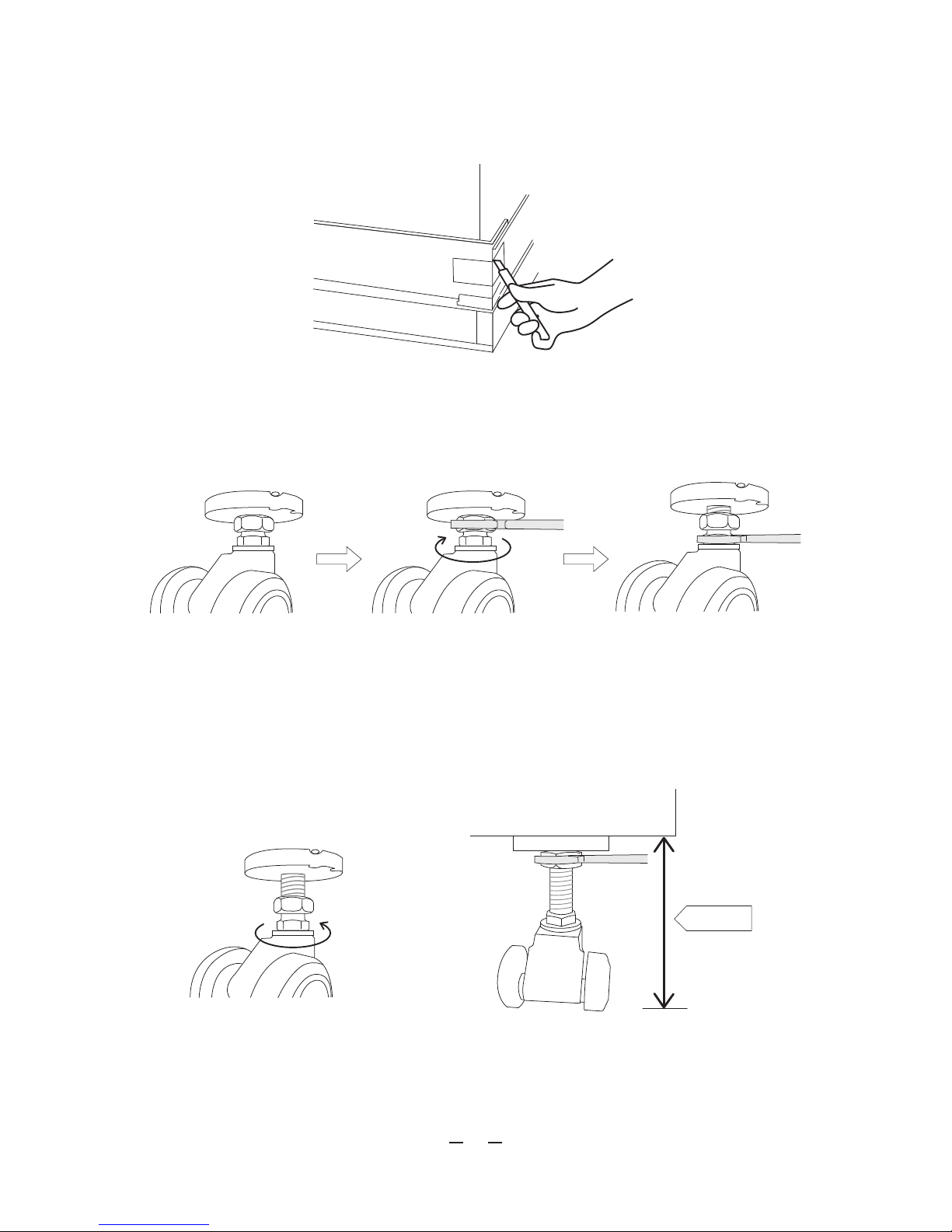
(5) Cut the tape at the bottom 4 corners of the cardboard box and open the corners.
(6) Extend the length of the 4 casters at the bottom.
(7) Secure the casters into place.
When the base of the product is 100 mm from the base of the cardboard box, secure the
upper nut by rotating it anticlockwise.
Position after unboxing
Extend the caster by rotating
the lower nut clockwise.
Use the supplied spanner to
loosen the upper nut by rotating it
clockwise. (View from the top)
100mm
5

(9) Remove the cardboard from the upper side.
(10)
Place the supplied slopes at the 2 locations on the upper side indicated in the illustration.
Remove the cardboard from the
upstream side by cutting at the
locations indicated with dotted lines.
There are no dotted lines on the actual
cardboard box.
Slope
(8) Remove the 2 pieces of cardboard packaging from the bottom center of the product.
There two locations are at the front and back.
Align the edge of the slope with the position indicated by the arrow.
6
 Loading...