

Page 1
OPERATING INSTRUCTIONS MANUAL
MANUEL D’INSTRUCTIONS D’UTILISATION
MANUAL DE INSTRUCCIONES DE FUNCIONAMIENTO
BETRIEBSANLEITUNG
MANUAL DE OPERACIONES Y MANTENIMIENTO
HIGH PRESSURE COIL NAILER
CLOUEUSE À BOBINE HAUTE
PRESSION
CLAVADORA DE ALTA PRESIÓN PARA
CLAVOS EN BOBINA
HOCHDRUCK-COILNAGLER
CHIODATRICE A BOBINA AD ALTA
PRESSIONE
INDEX ENGLISH Page 1 to 4
INDEX FRANÇAIS Page 5 à 9
ÍNDICE ESPAÑOL Página 10 a 14
INDEX DEUTSCH Seite 15 bis 19
INDICE ANALITICO ITALIANO Pagine da 20 a 24
Before using the tool, read and understand tool labels and Safety instruction manual and Operating
instructions manual. Failure to follow warnings could result in serious injury.
Keep these instructions with the tool for future reference.
Veillez à lire et bien comprendre les étiquettes et le Manuel d’instructions sur la sécurité et le Manuel
d’instructions d’utilisation avant d’utiliser cet outil. Tout manquement au respect des avertissements
peut entraîner des blessures graves.
Conservez ces instructions avec l’outil pour toute consultation ultérieure.
Lea y comprenda las etiquetas, el manual de instrucciones de seguridad y el manual de instrucciones
de funcionamiento de la herramienta antes de usarla. El incumplimiento de las advertencias puede
provocar lesiones graves.
Conserve estas instrucciones junto con la herramienta para futuras consultas.
Lesen Sie vor der Verwendung des Werkzeugs die Beschriftungen am Werkzeug, die
Sicherheitsanleitung und die Betriebsanleitung sorgfältig durch. Das Nichtbefolgen der Warnungen
kann zu schweren Verletzungen führen.
Bewahren Sie diese Anweisungen zum späteren Nachschlagen mit dem Werkzeug zusammen auf.
Prime di utilizzare l'utensile, leggere e comprendere le etichette e i manuali Istruzioni di sicurezza e
Istruzioni per l'uso dell'utensile. La mancata osservanza delle avvertenze potrebbe risultare in gravi
lesioni personali.
Conservare queste istruzioni insieme all'utensile per consultazioni future.
HN65(CE) HN65J(CE)
HN90F
Original Language English
WARNING
AVERTISSEMENT
ADVERTENCIA
WARNUNG
AVV ERT ENZ A
Page 2
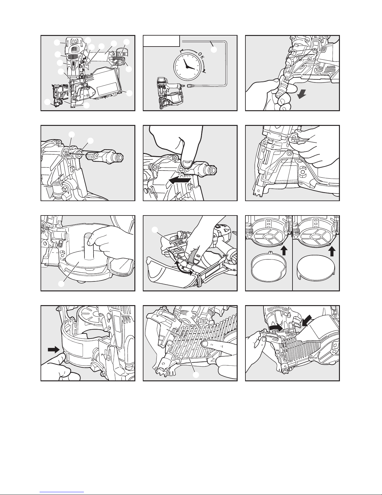
Fig.1 Fig.2 Fig.3 (HN65)
Fig.4 (HN65) Fig.5 (HN65) Fig.6
Fig.7 (HN65) Fig.8 (HN90F) Fig.9 (HN65J)
Fig.10 (HN65J) Fig.11 Fig.12
6
7
b
0
5
c
3
a
4
1
8
2
HN65J
9
170 psi
12 bar
320 psi
23 bar
2
1
1
2
1
2
3
2
40mm (1-1/2")
2
40 mm (1-1/2")65 mm (2-1/2")
5
4
6
7
8
Page 3
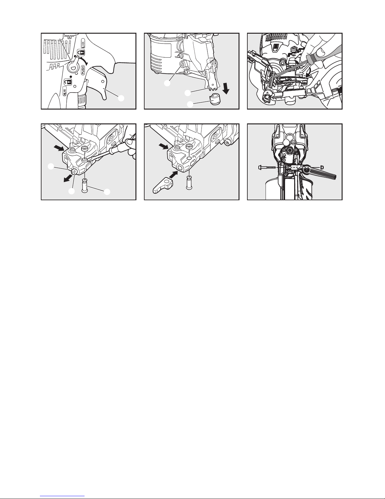
Fig.13 Fig.14 (HN65, HN90F) Fig.15 (HN90F)
Fig.16 (HN65J) Fig.17 (HN65J) Fig.18 (HN90F)
㻸㻻㻯㻷
㼁㻺㻸㻻㻯㻷
1
2
1
2
3
2
4
3
Page 4
1
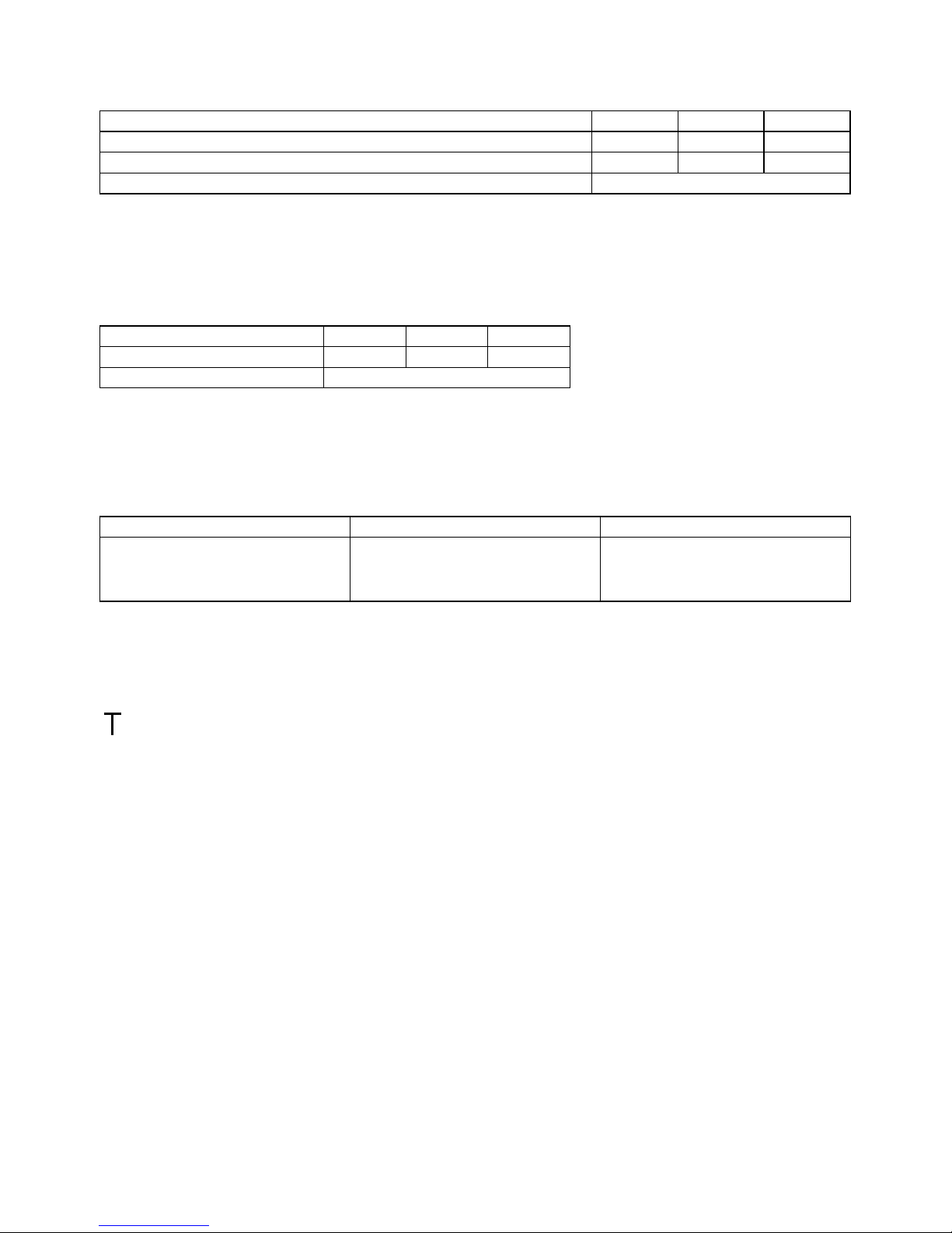
1. SPECIFICATIONS AND TECHNICAL DATA
1. NAME OF PARTS (SEE Fig.1)
2. TOOL SPECIFICATIONS
3. FASTENER SPECIFICATIONS
ENGLISH
OPERATING INSTRUCTIONS MANUAL
1 Frame 8 Exhaust Cover
2 Cylinder Cap 9 Trigger Lock Dial
3 Contact Arm 0 Plug
4 Nose a Aiming Guide Locator (HN65J)
5 Magazine b Adjust Dial
6 Trigger c Rafter Hook (HN90F)
7 Grip
PRODUCT NO. HN90F HN65 HN65J
HEIGHT 331mm 13" 301mm 11-7/8" 291mm 11-1/2"
WIDTH 126mm 5" 129mm 5" 102mm 4"
LENGTH 298mm 11-3/4" 291mm 11-1/2" 291mm 11-1/2"
WEIGHT 2.6 kg 5.7 lbs. 1.9 kg 4.3 lbs. 2.0 kg 4.4 lbs.
RECOMMENDED OPERATING PRESSURE 12 to 23 bar 170 to 320 p.s.i.
LOADING CAPACITY 300 Nails 400 Nails 100 Nails
AIR CONSUMPTION 3.4L at 18 bar / 257 p.s.i.
operating pressure
1.7L at 18 bar / 257 p.s.i.
operating pressure
1.4L at 18 bar / 257 p.s.i.
operating pressure
PRODUCT NO. HN90F HN65 HN65J
TYPE OF COLLATION
PLASTIC SHEET
COLLATED
WIRE WELDED PLASTIC SHEET
COLLATED
WIRE WELDED PLASTIC SHEET
COLLATED
NAIL LENGTH
45 to 75mm
1-3/4" to 3"
45 to 90mm
1-3/4" to 3-1/2"
32 to 65mm
1-1/4" to 2-1/2"
38 to 65mm
1-1/2" to 2-1/2"
40 to 65mm
1-1/2" to 2-1/2"
SHANK DIAMETER
2.5 to 2.9mm
.099" to .114"
2.5 to 3.8mm
.099" to .148"
2.5 to 2.9mm
.099" to .113"
2.1 to 3.3mm
.083" to .131"
3.3 to 4.1mm
.131" to .162"
SHANK TYPE Smooth, Screw Smooth, Ring, Screw Smooth, Screw Smooth, Ring, Screw Smooth
HEAD DIAMETER
5.5 to 7.7mm
.217" to .303"
6.0 to 7.7mm
.236" to .303"
5.0 to 7.0mm
.197" to .275"
7.2mm
.283"
Page 5
2
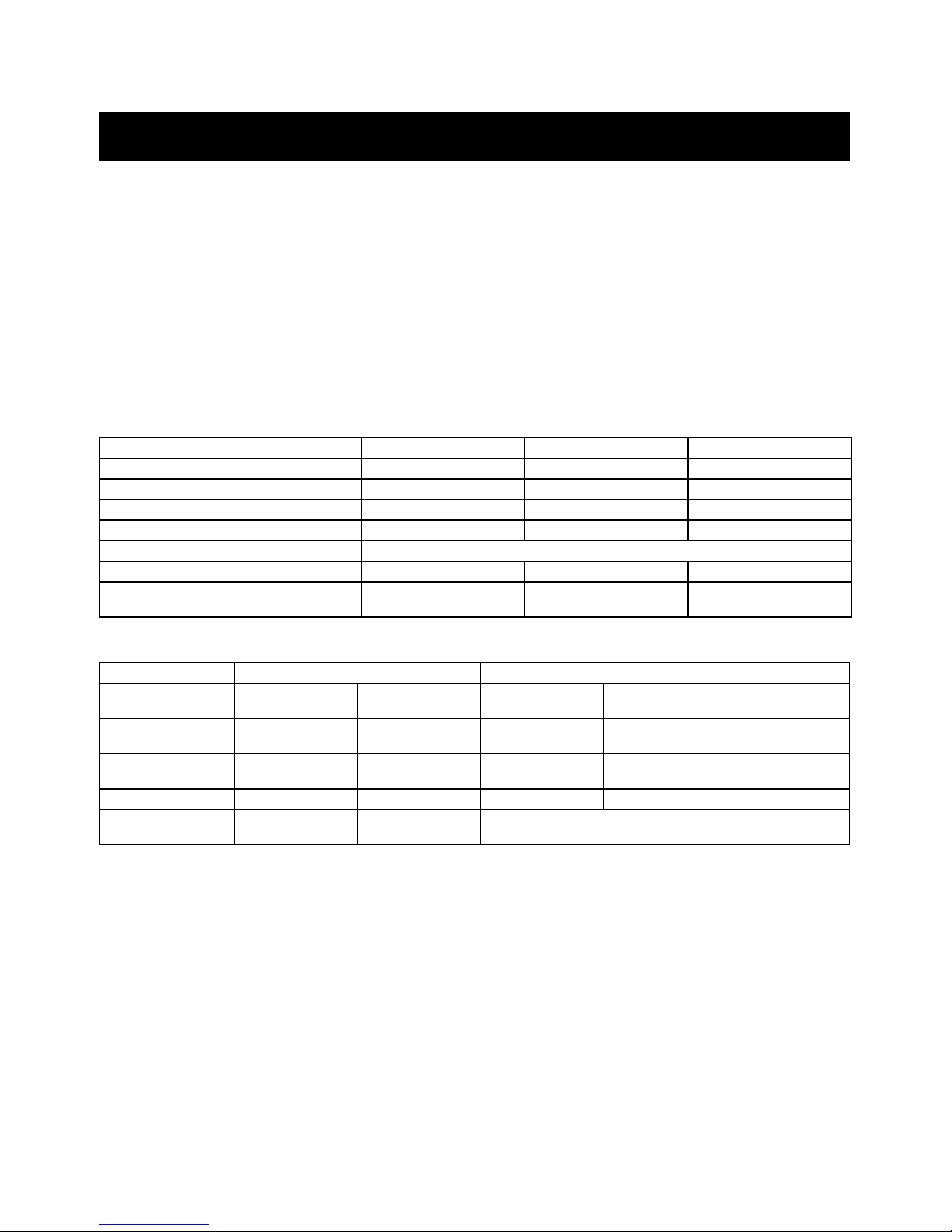
4. TECHNICAL DATA
NOISE
These values are determined and documented in accordance to EN12549:1999+A1:2008.
NOTE: These values are tool-related characteristic values and do not represent the noise generation at the point of use. Noise at the point
of use will for example depend on the working environment, the workpiece, the workpiece support, and the number of driving operations.
In addition, reference should be made to noise reduction measures.
NOTE: Workplace design can also serve to reduce noise levels, for example placing workpieces on sound-damping supports (see also ISO
11690-1).
VIBRATION
These values are determined and documented in accordance to ISO 28927-13
NOTE: The vibration emission value above is a tool-related characteristic value and does not represent the influence to the hand-arm-system when using the tool. Any influence to the hand-arm-system when using the tool will for example depend on the gripping force, the contact pressure force, the working direction, the adjustment of energy supply, the workpiece, the workpiece support.
5. APPLICATIONS
6. ABOUT PRODUCTION YEAR
This product bears production number at the lower part of the grip of the main body. The two digits of the number from left indicates the
production year.
HN90F HN65 HN65J
A-weighted single-event sound power level ------ LWA, 1s, d 93.1dB 90.0dB 89.9dB
A-weighted single-event emission sound pressure level at work station------ LpA, 1s, d 81.7dB 85.6dB 86.2dB
Uncertainty 3dB
HN90F HN65 HN65J
Vibration characteristic value 6.42 m/s
2
4.13 m/s
2
4.34 m/s2
Uncertainty 1.5 m/s
2
HN90F HN65 HN65J
∗ Floor and wall framing
∗ Subflooring
∗ Roof and wall sheathing
∗ Fencing
∗ Floor and wall framing
∗ Subflooring
∗ Roof and wall sheathing
∗ Fencing
∗ Fastening metal connectors for wood
construction.
(Example)
1 7 8 2 6 0 3 5 D
Year 2017
Page 6
3
2. AIR SUPPLY AND CONNECTIONS (Fig.2)
A. HOSES AND SUPPLY SOURCE
WHEN USING THE TOOL, BE SURE TO USE A SPECIAL AIR
COMPRESSOR AND AIR HOSE.
In order to improve its performance, it has set its working pressure
higher than the conventional nailers. To use the tool, you always
need the special air compressor 1 and the air hose 2 (MAX PowerLite Compressor and MAX PowerLite Hose).
Use of high pressure gas (for example, oxygen, acetylene, etc.)
causes abnormal combustion, possibly resulting in explosion.
Use only the special air compressor and air hose.
B. OPERATING PRESSURE:
12 to 23 bar / 170 to 320 p.s.i. Select the operating air pressure
within this range for best performance based upon the fastener
application and work surface. Using the lowest acceptable to
minimize noise, vibration and wear.
DO NOT EXCEED 23 bar / 320 p.s.i.
NOTICE:
Frequent, but not excessive, lubrication is required for the best
performance. Upon completion of operations, place 2 or 3 drops
of oil into the air plug inlet with the jet oiler.
3. INSTRUCTIONS FOR OPERATION
1. BEFORE OPERATION
1 Wear Safety Glasses or Goggles.
2 Do not connect the air supply.
3 Inspect screw tightness.
4 Check operation of the contact arm & trigger if moving
smoothly.
5 Connect the air supply.
6 Check the air-leakage. (The Tool must not have the air-
leakage.)
7 Hold the Tool with finger-off the trigger, then push the con-
tact arm against the work-piece. (The tool must not operate.)
8 Hold the Tool with contact arm free from work-piece and pull
the trigger. (The Tool must not operate.)
9 Disconnect the air supply.
2. OPERATION
ATTACHING THE CONTACT NOSE (HN65)
Attach the following contact noses depending on the nail head diameter used.
1 (Fig.3) Pull the contact nose to remove it.
2 (Fig.4,5) Aligning the rail with the contact arm, press the
contact nose as shown in the figure to fit it until it clicks.
NAIL LOADING
1 (Fig.6) Open the Magazine:
Pull up Door Latch 1 and swing Door open. Swing Magazine Cap open.
2 (Fig.7) (HN65) Check adjustment:
The Nail Support 2 can be moved up and down to four settings. To change setting pull up on the Nail Post and twist to
the correct step. The Nail Support should be adjusted correctly to the position indicated in inches and millimeters inside Magazine 3.
(Fig.8) (HN90F)
The nail support 2 can be moved up and down to four settings. The nail support moves down by turning it counterclockwise and moves up by turning it clockwise. The nail
support should be adjusted correctly to the position indicated in inches and millimeters.
(Fig.9,10) (HN65J) When using 40mm / 1-1/2" nails, attach
the nail support 2 in such a manner that a mark “40” can
been seen. When using 65mm / 2-1/2" ones, attach the nail
support 2 upside down.
To detach, push the latch on the back of the magazine with
a finger.
3 (Fig.11) Nail loading:
Place a coil of nails 4 over the Nail Post in the Magazine.
Uncoil enough nails to reach the Feed Pawl 5, and place
the second nail between the teeth on the Feed Pawl. The
nail heads fit in slot 6 on Nose.
4 (Fig. 12) Swing Magazine Cap 7 closed.
5 (Fig. 12) Close the Door 8.
Check that Door Latch 1 engages. (If it does not engage, check
that the nail heads are in the slot 6 on the Nose).
TEST OPERATION
1 Adjust the air pressure at 170 p.s.i. (12 bar) and connect the
air supply.
2 Without touching the Trigger, depress the Contact Arm
against the work-piece.
Pull the Trigger. (The tool should fire the fastener.)
3 With the tool off the work-piece, pull the Trigger.
Then depress the Contact Arm against the work-piece.
(Tool with red triggers should fire the fastener, but tool with
orange triggers should not.)
4 Adjust the air pressure as much as the lowest possible ac-
cording to the diameters and length of fastener and the
hardness of work-piece.
DRIVING FASTENERS
HN65J
This tool is assembled with FULL SEQUENTIAL TRIP.
HN65, HN90F
This tool is shipped with CONTACT TRIP WITH ANTI-DOUBLE
FIRE MECHANISM selected.
It is the responsibility of employer, tool owner or tool operator to
select the appropriate actuation system for the fastener application and training of tool operator before changing the trigger setting.
SWITCHING CONTACT TRIP WITH ANTI-DOUBLE FIRE
MECHANISM TO FULL SEQUENTIAL TRIP (Option) (HN90F,
HN65)
To change the trigger system, please contact MAX CO., LTD. authorized distributors and have them change the system.
SWITCHING FULL SEQUENTIAL TRIP (Option) TO CONTACT
TRIP WITH ANTI-DOUBLE FIRE MECHANISM (HN90F, HN65)
To change the trigger system, please contact MAX CO., LTD. authorized distributors and have them change the system.
CONTACT FIRE OPERATION (CONTACT TRIP) (HN90F,
HN65)
For contact fire operation, pull the Trigger and depress the Contact Arm against the work surface.
SINGLE FIRE OPERATION (ANTI-DOUBLE FIRE MECHANISM) (HN90F, HN65)
For single fire operation, depress the Contact Arm against the
work surface and pull the Trigger. A fastener will be driven. Release trigger. Begin again.
SINGLE FIRE OPERATION (FULL SEQUENTIAL TRIP) (For
tool with orange triggers)
For single fire operation, depress the Contact Arm against work
surface and pull trigger. A fastener will be driven. Release both
trigger and Contact Arm. Begin again.
Head Diameter Contact Nose Color
5.0 to 6.0mm
(.197" to .236")
Contact Nose S Black
6.0 to 7.0mm
(.236" to .275")
Contact Nose L Silver
Page 7

4
DRIVING DEPTH ADJUSTMENT DIAL
Adjust the driving depth by twisting the adjustment dial b as indicated below.
TRIGGER LOCK MECHANISM (Fig.13)
This tool has a Trigger Lock. The trigger should be locked at all
times until you intend to drive nail into the work surface. Push and
rotate the Trigger LOCK Dial 1 clockwise from LOCK to UNLOCK position immediately before driving nails. When fastening
is complete, push and rotate switch counterclockwise to LOCK
position.
CONTACT TIP (Fig.14) (HN90F, HN65)
Attach the Contact Tip 1 on the tip of Contact Arm 2, when driving nails to a soft material.
The Contact Tip can be kept on the Arm Cover 3 when not using.
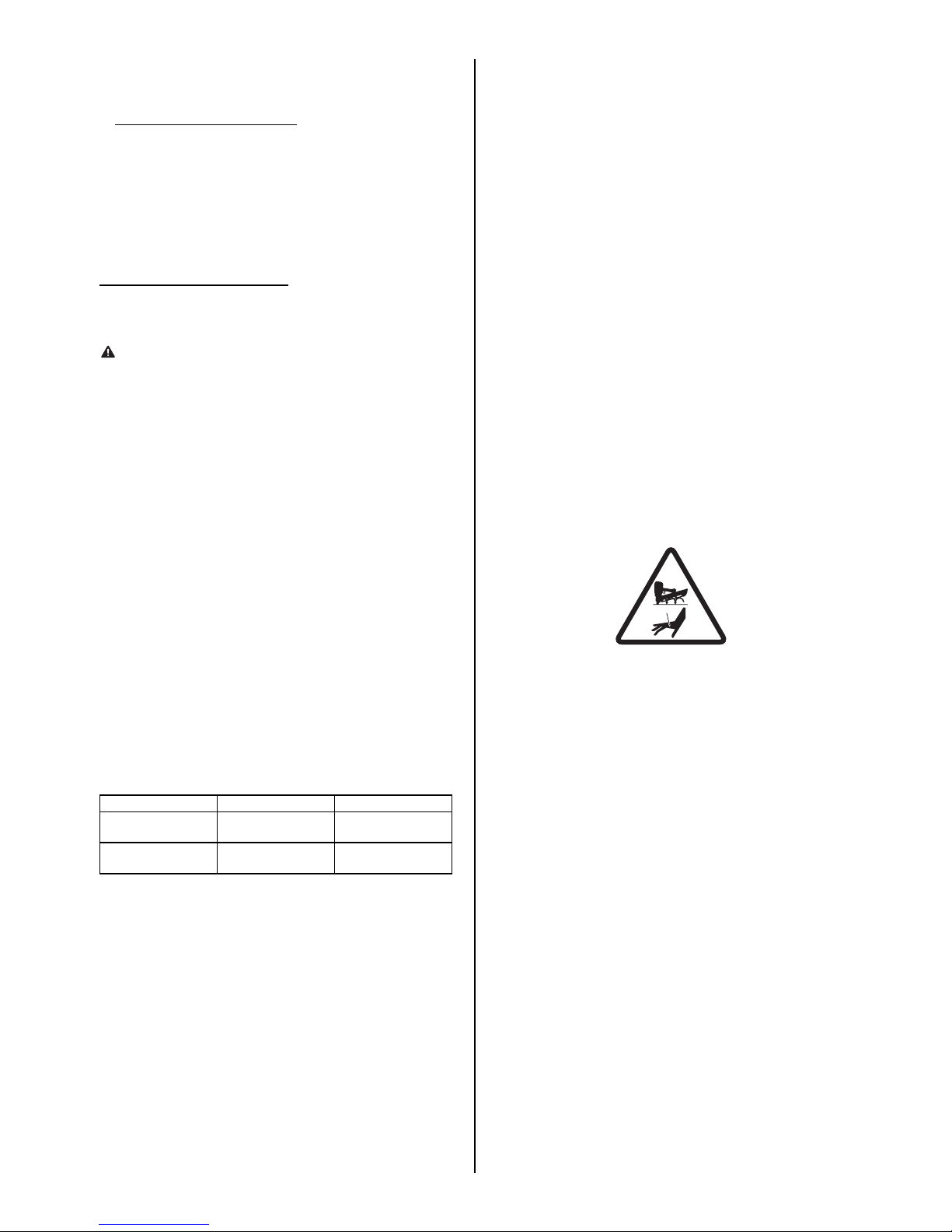
REMOVING JAMMED NAILS (Fig.15)
• ALWAYS disconnect the air supply.
• Wear gloves when removing jams; do not use bare hands
• Confirm that you have removed all nails from nose of tool
before reconnecting to air supply.
1 Disconnect the air supply.
2 Open the tool door and remove nails from inside of the mag-
azine.
3 Insert a thin metal stick in the tool nose and hit the metal
stick with a hammer or remove the jam with a flathead
screwdriver.
4 Put back the nails on the feed pawl and close the tool door.
WHEN USING THE TOOL FOR STEEL PLATES
(HN90F, HN65)
(HN65) This tool is exclusively designed for 1.6mm / 16Ga. to
2.3mm / 13Ga. thick light gauge steel.
(HN90F) This tool is exclusively designed for 1.6mm / 16Ga. to
3.2mm / 11Ga. thick light gauge steel.
When using it, comply with the Work Standards, considering the
object condition and work site environment.
1 Select appropriate nails according to the object thickness,
seeing the Nail Selection Criteria Chart.
∗ The nails may not be driven into the object depending on its
hardness or thickness.
∗ If the object is thicker than an appropriate range of thickness,
the nails may not be driven into it because of being bent.
2 If the thickness of the light gauge steel foundations material
used is 3.2mm / 11Ga., use the 2.9mm / .113" nails for steel
plate. (HN90F)
3 Never drive the nails directly into the light gauge steel be-
cause they will fly off, endangering you.
4 Be sure to apply the discharge outlet to the object at a right
angle. If applied obliquely, the nails will fly off, endangering
you.
5 Never use the nails for the roofs (roof foundations included)
or ceilings (ceiling foundations included).
6 If the nails are driven into the steel plate too deeply, their
holding force will be extremely reduced. When working with
the tool, fully check the driven conditions.
Nail Selection Criteria
REPLACING THE AIMING GUIDE LOCATOR
(HN65J)
The aiming guide locator is worn out depending on the frequency
of use.
If the machine cannot be easily held vertically when setting the
aiming guide locator in a hole in a metal fitting, it is about time to
replace.
Replace it in the following procedure:
1 (Fig.16) Remove a rubber washer 1 with a regular
screwdriver to pull out a pin 2. Push the nail leg guide 3
to remove the aiming guide locator 4.
2
(Fig.17) Attach a new aiming guide locator, set the pin and put
back the rubber washer.
When replacing the aiming guide locator, contact the nearest
MAX CO., LTD. authorized distributor.
CHANGING THE HOOK DIRECTION (HN90F)
(Fig.18) The hook can be directed in the two direction. Remove
the hexagon socket cap screw with hexagon wrench, change the
direction, and then, put back the bolt to reassemble.
PROCEDURE
1 Pulling the Trigger and keeping it
pulled.
2 Depressing the Contact Arm.
CONTACT TRIP WITH
ANTI-DOUBLE FIRE
MECHANISM
The tool fires a nail each time when the
Contact Arm is depressed.
SEQUENTIAL TRIP The tool cannot fire a nail.
PROCEDURE
1 Depressing the Contact Arm.
2 Pulling the Trigger and keeping it
pulled.
CONTACT TRIP WITH
ANTI-DOUBLE FIRE
MECHANISM
The tool fires a nail.
The tool cannot fire a second nail until
the Trigger is released.
SEQUENTIAL TRIP The tool fires a nail.
In order to fire a second nail, you should
both release the Trigger and remove the
Contact arm from the surface.
Deep Shallow
WARNING
Tool Diameter Length
Object thickness
(Total) range
Light gauge
steel thickness
HN65
HN90F
2.5mm
(.098")
45mm
(1-3/4")
25 to 35mm
(1" to 1-3/8")
1.6 to 2.3mm
(16Ga. to
13Ga.)
50mm
(2")
30 to 40mm
(1-1/8" to 1-1/2")
57mm
(2-1/4")
35 to 45mm
(1-3/8" to 1-3/4")
65mm
(2-1/2")
45 to 55mm
(1-1/2" to 1-1/8")
HN90F
2.9mm
(.113")
45mm
(1-3/4")
25 to 35mm
(1" to 1-3/8")
1.6 to 3.2mm
(16Ga. to
11Ga.)
50mm
(2")
30 to 40mm
(1-1/8" to 1-1/2")
57mm
(2-1/4")
35 to 45mm
(1-3/8" to 1-3/4")
65mm
(2-1/2")
45 to 55mm
(1-1/2" to 1-1/8")
Wood
Object thickness
(Total) range
Penetration amount
Light gauge steel:
(HN65) 1.6mm (16Ga.) to 2.3mm
(13Ga.) thick
(HN90F) 1.6mm (16Ga.) to 3.2mm
(11Ga.) thick
∗ For the 3.2mm (11Ga.) thick light gauge steel, use the
2.9mm (.113") nails for steel plates. (HN90F)
Page 8

25
HN65(CE)
EXPLODED
VIEW AND SPARE
PARTS LIST
SCHEMA ECLATE ET
LISTE DES PIECES
DE RECHANGE
DESPIECE DE LA
MAQUINA Y LISTA
DE RECAMBIOS
EINZELTEILDAR-
STELLUNG UND
ERSATZTEILLISTE
ESPLOSO DEI
COMPONENTI ED
ELENCO DELLE
PARTI DI RICAMBIO
1
2
4
5
6
7
8
9
10
11
12
13
15
16
19
17
23
24
26
32
21
27
28
29
156
A
3
18
20
B
77
78
79
81
82
96
98
100
97
103
110
108
80
94
95
104
112
109
113
116
117
118
119
120
114
111
115
22
31
33
59
57
58
73
62
64
75
63
56
44
45
46
47
48
49
51
52
53
54
48
60
145
68
65
105
69
72
36
76
20
30
33
106
91
80
34
101
66
67
107
43
50
55
111
127
B
128
124
126
80
37
40
35
38
39
131
122
121
A
123
99
21
31
41
102
125
85
89
90
83
84
91
87
80
88
86
132
93
133
134
92
67
103
14
146
O-RING KIT
Parts marked
in included
are
the O-ring kit
147
72
158
64
71
70
48
49
51
53
56
58
48
157
159
154
155
160
52
54
57
59
148
6
74
130
129
161
Page 9

26
HN65(CE)
ITEM
NO.
PART
NO.
MATERIAL ENGLISH FRANÇAIS ESPAÑOL DEUTSCH ITALIANO
1 HN10338 Steel SCREW 5X36 VIS 5X36 TORNILLO 5X36 SCHRAUBE 5X36 VITE 5X36
2 HN11467 Aluminum CYLINDER CAP
CAPUCHON DE
CYLINDRE
TAPA DEL CILINDRO ZYLINDERDECKEL CALOTTA CILINDRO
3 HN11363 Steel, Rubber CYLINDER CAP SEAL
JOINT DE CAPUCHON DE
CYLINDRE
JUNTA ESTANCA DE
TAPA DEL CILINDRO
ZYLINDERDECKELDICHTUNG
GUARNIZIONE CALOTTA
CILINDRO
4 KK23650 Steel
COMPRESSION SPRING 3650 RESSORT À PRESSION 3650
MUELLE DE COMPRESIÓN
3650
DRUCKFEDER 3650
MOLLA DI COMPRESSIONE
3650
5 HN11364 Rubber PISTON STOP BUTÉE DE PISTON TOPE DEL PISTÓN KOLBENANSCHLAG ARRESTO PISTONE
6 HH11136 Rubber O-RING AS568-132
JOINT TORIQUE AS568132
JUNTA TÓRICA AS568132
O-RING AS568-132
GUARNIZIONE
CIRCOLARE AS568-132
7 HH19752 Rubber O-RING 1A 2X31.5
JOINT TORIQUE 1A
2X31,5
JUNTA TÓRICA 1A
2X31,5
O-RING 1A 2X31,5
GUARNIZIONE
CIRCOLARE 1A 2X31,5
8 HN11396 Polyacetal HEAD VALVE PISTON
PISTON DE
DISTRIBUTEUR AVANT
PISTÓN DE VÁLVULA DE
IMPULSIÓN
DRUCKVENTILKOLBEN
PISTONE VALVOLA DI
TESTA
9 HN11367 Aluminum HEAD VALVE GUIDE
GUIDE DE
DISTRIBUTEUR AVANT
GUÍA DE VÁLVULA DE
IMPULSIÓN
DRUCKVENTILFÜHRUNG
GUIDA VALVOLA DI
TESTA
10 HH14904 Rubber O-RING AS568-032
JOINT TORIQUE AS568032
JUNTA TÓRICA AS568032
O-RING AS568-032
GUARNIZIONE
CIRCOLARE AS568-032
11 HH11805 Rubber O-RING P22A JOINT TORIQUE P22A JUNTA TÓRICA P22A O-RING P22A
GUARNIZIONE
CIRCOLARE P22A
12 HN70108 Magnesium, Steel MAIN PISTON UNIT PISTON PRINCIPAL PISTÓN PRINCIPAL HAUPTKOLBENEINHEIT
UNITÀ PISTONE
PRINCIPALE
13 HN11370 Rubber CYLINDER SEAL JOINT DE CYLINDRE
JUNTA ESTANCA DEL
CILINDRO
ZYLINDERDICHTUNG GUARNIZIONE CILINDRO
14 EE31105 Steel PLANE WASHER 1-6 RONDELLE PLATE 1-6 ARANDELA 1-6 UNTERLEGSCHEIBE 1-6 RONDELLA PIANA 1-6
15 HH11135 Rubber O-RING 1A P31.5 JOINT TORIQUE 1A P31,5 JUNTA TÓRICA 1A P31,5 O-RING 1A P31,5
GUARNIZIONE
CIRCOLARE 1A P31,5
16 HN81140 Aluminum CYLINDER A CYLINDRE A CILINDRO "A" ZYLINDER A CILINDRO "A"
17 HH11174 Rubber O-RING 1A P35 JOINT TORIQUE 1A P35 JUNTA TÓRICA 1A P35 O-RING 1A P35
GUARNIZIONE
CIRCOLARE 1A P35
18 HN11369 Aluminum CYLINDER B CYLINDRE B CILINDRO "B" ZYLINDER B CILINDRO "B"
19 HN11384 Rubber BUMPER AMORTISSEUR AMORTIGUADOR STOSSDÄMPFER AMMORTIZZATORE
20 HN11374 Nylon EXHAUST COVER
CAPOT DE
L’ÉCHAPPEMENT
CUBIERTA DE ESCAPE ABLUFTGITTER COPERTURA SCARICO
21 HN81086 Nylon, Rubber EXHAUST COVER UNIT
UNITÉ DU CAPOT DE
L’ÉCHAPPEMENT
UNIDAD DE CUBIERTA DE
ESCAPE
ABLUFTGITTER-EINHEIT
UNITÀ COPERTURA
SCARICO
22 HN11376 Polyester FILTER B FILTRE B FILTRO "B" FILTER B FILTRO "B"
23 HN11375 Stainless steel FILTER A FILTRE A FILTRO "A" FILTER A FILTRO "A"
24 HN11361 Magnesium FRAME CHÂSSIS ARMAZÓN GEHÄUSE TELAIO
26 HN10810
Polyethylene
terephthalate
NAME LABEL A
ÉTIQUETTE NOMINATIVE AETIQUETA DE NOMBRE
"A"
NAMENSSCHILD A ETICHETTA NOME "A"
27 HN10811
Polyethylene
terephthalate
NAME LABEL B
ÉTIQUETTE NOMINATIVE BETIQUETA DE NOMBRE
"B"
NAMENSSCHILD B ETICHETTA NOME "B"
28 KK23507 Steel
COMPRESSION SPRING
3507
RESSORT À PRESSION
3507
MUELLE DE
COMPRESIÓN 3507
DRUCKFEDER 3507
MOLLA DI
COMPRESSIONE 3507
29 CN35075 Nylon TRIGGER LOCK LEVER
LEVIER DE BLOCAGE DE
LA COMMANDE
PALANCA DE SEGURO
DEL DISPARADOR
AUSLÖSESPERRHEBEL
LEVA DI BLOCCO DEL
GRILLETTO
30 FF21235 Steel ROLL PIN 3X30
GOUPILLE ÉLASTIQUE
3X30
PASADOR DE RODILLO
3X30
SPANNSTIFT 3X30 PERNO ROTANTE 3X30
31 HH11120 Rubber O-RING AS568-009
JOINT TORIQUE AS568009
JUNTA TÓRICA AS568009
O-RING AS568-009
GUARNIZIONE
CIRCOLARE AS568-009
32 HN11442 Aluminum PIPE TUBE TUBO ROHR TUBO
33 HH19127 Rubber O-RING 1A 1.5X6.6
JOINT TORIQUE 1A
1,5X6,6
JUNTA TÓRICA 1A
1,5X6,6
O-RING 1A 1,5X6,6
GUARNIZIONE
CIRCOLARE 1A 1,5X6,6
34 CN35074 Polyacetal TRIGGER LOCK DIAL
MOLETTE DE BLOCAGE
DE LA COMMANDE
DISCO DE BLOQUEO DEL
DISPARADOR
AUSLÖSESPERREEINSTELLRAD
MANOPOLA DI BLOCCO
DEL GRILLETTO
35 HN10379 Rubber GRIP COVER
REVÊTEMENT DE LA
POIGNÉE
CUBIERTA DE
EMPUÑADURA
GRIFFÜBERZUG
COPERTURA
IMPUGNATURA
36 HH14906 Rubber O-RING AS568-133
JOINT TORIQUE AS568133
JUNTA TÓRICA AS568133
O-RING AS568-133
GUARNIZIONE
CIRCOLARE AS568-133
37 TA17024
Polyacetal,
Polyethylene
END CAP FILTER KM-23
FILTRE DU CAPUCHON
D’EXTRÉMITÉ KM-23
FILTRO DE TAPÓN
TERMINAL KM-23
ENDKAPPENFILTER KM23
FILTRO PEZZO DI
CHIUSURA FINALE KM-
23
38 HH19102 Rubber O-RING 1A 2.4X31.8
JOINT TORIQUE 1A
2.4X31.8
JUNTA TÓRICA 1A
2,4X31,8
O-RING 1A 2,4X31,8
GUARNIZIONE
CIRCOLARE 1A 2,4X31,8
39 HN12037 Aluminum END CAP
CAPUCHON
D’EXTRÉMITÉ
TAPÓN TERMINAL ENDKAPPE
PEZZO DI CHIUSURA
FINALE
40 TT05416 Steel, Rubber AIR PLUG PRISE D’AIR TOMA DE AIRE LUFTSTECKER INNESTO RAPIDO ARIA
Page 10

27
41 HN10316 Rubber END PLUG CAP
CAPUCHON DE LA PRISE
D’EXTRÉMITÉ
TAPÓN TERMINAL DE
TOMA
ENDKAPPENSTOPFEN
TAPPO DI CHIUSURA
FINALE
42
43 BB40437 Steel SCREW 5X30 VIS 5X30 TORNILLO 5X30 SCHRAUBE 5X30 VITE 5X30
44 HN10820 Aluminum FEED NOZZLE BUSE DE CHARGEMENT
BOQUILLA DE
ALIMENTACIÓN
EINFÜLLSTUTZEN
UGELLO DI
ALIMENTAZIONE
45 HH19722 Rubber O-RING 1A 1.5X5 JOINT TORIQUE 1A 1,5X5 JUNTA TÓRICA 1A 1,5X5 O-RING 1A 1,5X5
GUARNIZIONE
CIRCOLARE 1A 1,5X5
46 HN10043 Steel PILOT CAP CAPUCHON PILOTE TAPÓN PILOTO PILOTKAPPE
PEZZO DI CHIUSURA
PILOTA
47 HN10018 Rubber PILOT SEAL JOINT PILOTE JUNTA ESTANCA PILOTO PILOTDICHTUNG GUARNIZIONE PILOTA
48 HH12105 Rubber O-RING 1A 1.5X12.8
JOINT TORIQUE 1A
1,5X12,8
JUNTA TÓRICA 1A
1,5X12,8
O-RING 1A 1,5X12,8
GUARNIZIONE
CIRCOLARE 1A 1,5X12,8
49 HN10016 Polyacetal
TRIGGER VALVE
HOUSING
LOGEMENT DE LA VALVE
DE DÉCLENCHEMENT
CARCASA DE VÁLVULA
DEL DISPARADOR
AUSLÖSEVENTILGEHÄUSE
ALLOGGIAMENTO
VALVOLA GRILLETTO
50 HN81098 Polyacetal, Rubber PILOT VALVE ASSY
ENSEMBLE DU
DISTRIBUTEUR PILOTE
CONJUNTO DE VÁLVULA
PILOTO
PILOTVENTILBAUGRUPPE
GRUPPO VALVOLA
PILOTA
51 HH11208 Rubber O-RING 1B P6 JOINT TORIQUE 1B P6 JUNTA TÓRICA 1B P6 O-RING 1B P6
GUARNIZIONE
CIRCOLARE 1B P6
52 HN10017 Polyacetal PILOT VALVE DISTRIBUTEUR PILOTE VÁLVULA PILOTO PILOTVENTIL VALVOLA PILOTA
53 HH11132 Rubber O-RING 1A P10A JOINT TORIQUE 1A P10A JUNTA TÓRICA 1A P10A O-RING 1A P10A
GUARNIZIONE
CIRCOLARE 1A P10A
54 KK23619 Steel
COMPRESSION SPRING
3619
RESSORT À PRESSION
3619
MUELLE DE
COMPRESIÓN 3619
DRUCKFEDER 3619
MOLLA DI
COMPRESSIONE 3619
55 HN81311
Steel, Polyacetal,
Rubber
TRIGGER VALVE STEM
ASSY
ENSEMBLE DE TIGE DE
MANŒUVRE DU
DÉCLENCHEUR
CONJUNTO DE VÁSTAGO
DE VÁLVULA DEL
DISPARADOR
AUSLÖSEVENTILSCHAFTBAUGRUPPE
GRUPPO STELO
VALVOLA GRILLETTO
56 HH19707 Rubber O-RING 1A 1.4X2.5
JOINT TORIQUE 1A
1,4X2,5
JUNTA TÓRICA 1A
1,4X2,5
O-RING 1A 1,4X2,5
GUARNIZIONE
CIRCOLARE 1A 1,4X2,5
57 HN10353 Steel, Rubber TRIGGER VALVE STEM
TIGE DE MANŒUVRE DU
DÉCLENCHEUR
VÁSTAGO DE VÁLVULA
DEL DISPARADOR
AUSLÖSEVENTILSCHAFT
STELO VALVOLA
GRILLETTO
58 HH19214 Rubber O-RING 1B 1.5X3 JOINT TORIQUE 1B 1,5X3 JUNTA TÓRICA 1B 1,5X3 O-RING 1B 1,5X3
GUARNIZIONE
CIRCOLARE 1B 1,5X3
59 HN10019 Steel TRIGGER VALVE CAP
CAPUCHON DE LA VALVE
DU DÉCLENCHEUR
TAPÓN DE VÁLVULA DEL
DISPARADOR
AUSLÖSEVENTILKAPPE
CAPPELLETTO VALVOLA
GRILLETTO
60 HN80077
Steel, Polyacetal,
Rubber
TRIGGER ASSY
ENSEMBLE DU
DÉCLENCHEUR
CONJUNTO DE
DISPARADOR
AUSLÖSER-BAUGRUPPE GRUPPO GRILLETTO
62 CN35115 Steel CONTACT LEVER A LEVIER À CONTACT A
PALANCA DE CONTACTO
"A"
KONTAKTHEBEL A LEVA Dl CONTATTO "A"
63 HS10147 Polyacetal TRIGGER DÉCLENCHEUR DISPARADOR AUSLÖSER GRILLETTO
64 FF22402 Stainless steel ROLL PIN 3X16
GOUPILLE ÉLASTIQUE
3X16
PASADOR DE RODILLO
3X16
SPANNSTIFT 3X16 PERNO ROTANTE 3X16
65 HN11399 Nylon SWITCH LEVER A
LEVIER DE
COMMUTATEUR A
PALANCA
CONMUTADORA "A"
SCHALTHEBEL A LEVA INTERRUTTORE "A"
66 HN10786 Stainless steel ARM GUIDE PLATE PLAQUE GUIDE DU BRAS
PLACA DE GUÍA DEL
BRAZO
ARMLEITBLECH
PIASTRA GUIDA
BRACCIO
67 HN10785 Rubber CONTACT BUMPER
AMORTISSEUR DE
CONTACT
AMORTIGUADOR DE
CONTACTO
KONTAKTSTOSSFÄNGER
AMMORTIZZATORE
CONTATTO
68 HS10146 Steel SWITCH LEVER B
LEVIER DE
COMMUTATEUR B
PALANCA
CONMUTADORA "B"
SCHALTHEBEL B LEVA INTERRUTTORE "B"
69 CN34500 Steel SWITCH SPRING
RESSORT DU
COMMUTATEUR
MUELLE CONMUTADOR SCHALTFEDER MOLLA INTERRUTTORE
70 KK23735 Steel
COMPRESSION SPRING
3735
RESSORT À PRESSION
3735
MUELLE DE
COMPRESIÓN 3735
DRUCKFEDER 3735
MOLLA DI
COMPRESSIONE 3735
71 KK23736 Steel
COMPRESSION SPRING
3736
RESSORT À PRESSION
3736
MUELLE DE
COMPRESIÓN 3736
DRUCKFEDER 3736
MOLLA DI
COMPRESSIONE 3736
72 KK23129 Steel
COMPRESSION SPRING
3129
RESSORT À PRESSION
3129
MUELLE DE
COMPRESIÓN 3129
DRUCKFEDER 3129
MOLLA DI
COMPRESSIONE 3129
73 HN10784 Nylon ARM GUIDE GUIDE DU BRAS GUÍA DEL BRAZO ARMFÜHRUNG GUIDA BRACCIO
74 KK23912 Steel
COMPRESSION SPRING
3912
RESSORT À PRESSION
3912
MUELLE DE
COMPRESIÓN 3912
DRUCKFEDER 3912
MOLLA DI
COMPRESSIONE 3912
75 HN10356 Steel CONTACT ARM A BRAS DE CONTACT A BRAZO DE CONTACTO "A" KONTAKTARM A
BRACCIO DI CONTATTO
"A"
76 HN10026 Polyacetal ADJUST DIAL MOLETTE DE RÉGLAGE DISCO DE AJUSTE EINSTELLRAD
MANOPOLA DI
REGOLAZIONE
77 HN11389 Nylon ADJUST SPACER
ENTRETOISE
D’AJUSTEMENT
ESPACIADOR DE AJUSTE
EINSTELLABSTANDSHALTER
DISTANZIATORE DI
REGOLAZIONE
78 HH14164 Rubber O-RING AS 568-030
JOINT TORIQUE AS 568030
JUNTA TÓRICA AS 568030
O-RING AS 568-030
GUARNIZIONE
CIRCOLARE AS 568-030
HN65(CE)
ITEM
NO.
PART
NO.
MATERIAL ENGLISH FRANÇAIS ESPAÑOL DEUTSCH ITALIANO
Page 11

28
79 HN11380 Steel NOSE BUSE NARIZ NASE PUNTA
80 EE39602 Rubber RUBBER WASHER 7
RONDELLE DE
CAOUTCHOUC 7
ARANDELA DE CAUCHO 7 GUMMISCHEIBE 7 RONDELLA DI GOMMA 7
81 BB40213 Steel SCREW 6X25 VIS 6X25 TORNILLO 6X25 SCHRAUBE 6X25 VITE 6X25
82 FF31250 Steel PARALLEL PIN 1250
GOUPILLE PARALLÈLE
1250
PERNO PARALELO 1250 ZYLINDERSTIFT 1250 PERNO PARALLELO 1250
83 CN33679 Steel DOOR LATCH VERROU DE PORTE CIERRE DE PUERTA KLAPPENVERSCHLUSS
DISPOSITIVO DI
CHIUSURA
SPORTELLINO
84 KK33353 Steel TORSION SPRING 3353
RESSORT DE TORSION
3353
MUELLE DE TORSIÓN
3353
TORSIONSFEDER 3353
MOLLA Dl TORSIONE
3353
85 HN11463 Steel RATCHET A CLIQUET A TRINQUETE "A" SPERRKLINKE A ROCCHETTO "A"
86 CN34479 Steel RATCHET B CLIQUET B TRINQUETE "B" SPERRKLINKE B ROCCHETTO "B"
87 KK23282 Steel
COMPRESSION SPRING
3282
RESSORT À PRESSION
3282
MUELLE DE
COMPRESIÓN 3282
DRUCKFEDER 3282
MOLLA DI
COMPRESSIONE 3282
88 FF41281 Steel STEP PIN 1281
BOULON À GRADINS
1281
PERNO ESCALONADO
1281
STUFENBOLZEN 1281 PERNO SCALARE 1281
89 FF41599 Steel STEP PIN 1599
BOULON À GRADINS
1599
PERNO ESCALONADO
1599
STUFENBOLZEN 1599 PERNO SCALARE 1599
90 HN11382 Steel DOOR PORTE PUERTA KLAPPE SPORTELLINO
91 EE39609 Rubber
RUBBER WASHER
1.8X6X2
RONDELLE DE
CAOUTCHOUC 1,8X6X2
ARANDELA DE CAUCHO
1,8X6X2
GUMMISCHEIBE 1,8X6X2
RONDELLA IN GOMMA
1,8X6X2
92 EE39172 Steel
PLANE WASHER
5.1X12X1.2
RONDELLE PLATE
5,1X12X1,2
ARANDELA 5,1X12X1,2
UNTERLEGSCHEIBE
5,1X12X1,2
RONDELLA PIANA
5,1X12X1,2
93 BB40427 Steel SCREW 4X8 VIS 4X8 TORNILLO 4X8 SCHRAUBE 4X8 VITE 4X8
94 BB40407 Steel SCREW 5X20 VIS 5X20 TORNILLO 5X20 SCHRAUBE 5X20 VITE 5X20
95 HN12405 Steel CONTACT BOLT BOULON DE CONTACT PERNO DE CONTACTO KONTAKTBOLZEN BULLONE DI CONTATTO
96 HH11903 Rubber O-RING 1A 1.2X4 JOINT TORIQUE 1A 1,2X4 JUNTA TÓRICA 1A 1,2X4 O-RING 1A 1,2X4
GUARNIZIONE
CIRCOLARE 1A 1,2X4
97 JJ80010 Steel U-RETAINING RING 3.2
BAGUE-U DE RETENUE
3,2
ANILLO DE RETENCIÓN
EN "U" 3,2
U-HALTERING 3,2
ANELLO DI FISSAGGIO A
"U" 3,2
98 KK29136 Steel
COMPRESSION SPRING
3952
RESSORT À PRESSION
3952
MUELLE DE
COMPRESIÓN 3952
DRUCKFEDER 3952
MOLLA DI
COMPRESSIONE 3952
99 HN70111 Steel CONTACT ARM B UNIT
UNITÉ DU BRAS DE
CONTACT B
BRAZO DE CONTACTO
“B”
KONTAKTARM-EINHEIT B
UNITÀ BRACCIO DI
CONTATTO "B"
100 HN81108 Steel, Rubber CONTACT NOSE L ASSY
ENSEMBLE DE LA BUSE
DE CONTACT L
CONJUNTO DE NARIZ DE
CONTACTO "L"
KONTAKTNASEBAUGRUPPE L
GRUPPO PUNTA DI
CONTATTO "L"
101 HN81107 Steel, Rubber CONTACT NOSE S ASSY
ENSEMBLE DE LA BUSE
DE CONTACT S
CONJUNTO DE NARIZ DE
CONTACTO "S"
KONTAKTNASEBAUGRUPPE S
GRUPPO PUNTA DI
CONTATTO "S"
102 FF31602 Steel PARALLEL PIN 1602
GOUPILLE PARALLÈLE
1602
PERNO PARALELO 1602 ZYLINDERSTIFT 1602 PERNO PARALLELO 1602
103 HN11984 Steel CHECK PAWL CLIQUET D’ARRÊT
TRINQUETE DE
RETENCIÓN
PRÜFKLINKE
NOTTOLINO DI
CONTROLLO
104 KK33221 Steel TORSION SPRING 3221
RESSORT DE TORSION
3221
MUELLE DE TORSIÓN
3221
TORSIONSFEDER 3221
MOLLA Dl TORSIONE
3221
105 KK23653 Steel
COMPRESSION SPRING
3653
RESSORT À PRESSION
3653
MUELLE DE
COMPRESIÓN 3653
DRUCKFEDER 3653
MOLLA DI
COMPRESSIONE 3653
106 KK23788 Steel
COMPRESSION SPRING
3788
RESSORT À PRESSION
3788
MUELLE DE
COMPRESIÓN 3788
DRUCKFEDER 3788
MOLLA DI
COMPRESSIONE 3788
107 KK23710 Steel
COMPRESSION SPRING
3710
RESSORT À PRESSION
3710
MUELLE DE
COMPRESIÓN 3710
DRUCKFEDER 3710
MOLLA DI
COMPRESSIONE 3710
108 FF41817 Steel STEP PIN 1817
BOULON À GRADINS
1817
PERNO ESCALONADO
1817
STUFENBOLZEN 1817 PERNO SCALARE 1817
109 HN11462 Steel FEED PAWL
CLIQUET
D’ALIMENTATION
TRINQUETE DE AVANCE VORSCHUBKLINKE
NOTTOLINO DI
ALIMENTAZIONE
110 HN11385 Nylon ARM COVER CAPOT DU BRAS CUBIERTA DE BRAZO ARMABDECKUNG COPERTURA BRACCIO
111 CC00401 Steel HEX NUT M5 ÉCROU HEXAGONAL M5 TUERCA HEXAGONAL M5 SECHSKANTMUTTER M5 DADO ESAGONALE M5
112 HH11113 Rubber O-RING 1A P9 JOINT TORIQUE 1A P9 JUNTA TÓRICA 1A P9 O-RING 1A P9
GUARNIZIONE
CIRCOLARE 1A P9
113 HN11390 Steel FEED PISTON
PISTON
D’ALIMENTATION
PISTÓN DE AVANCE VORSCHUBKOLBEN
PISTONE DI
ALIMENTAZIONE
114 HH11106 Rubber O-RING 1A P16 JOINT TORIQUE 1A P16 JUNTA TÓRICA 1A P16 O-RING 1A P16
GUARNIZIONE
CIRCOLARE 1A P16
115 KK23724 Steel
COMPRESSION SPRING
3724
RESSORT À PRESSION
3724
MUELLE DE
COMPRESIÓN 3724
DRUCKFEDER 3724
MOLLA DI
COMPRESSIONE 3724
116 KK23173 Steel
COMPRESSION SPRING
3173
RESSORT À PRESSION
3173
MUELLE DE
COMPRESIÓN 3173
DRUCKFEDER 3173
MOLLA DI
COMPRESSIONE 3173
117 CN37998 Rubber FEED PISTON STOP
ARRÊT DU PISTON
D’ALIMENTATION
TOPE DE PISTÓN DE
AVANCE
VORSCHUBKOLBENANSCHLAG
ARRESTO PISTONE DI
ALIMENTAZIONE
HN65(CE)
ITEM
NO.
PART
NO.
MATERIAL ENGLISH FRANÇAIS ESPAÑOL DEUTSCH ITALIANO
Page 12

29
118 CN35285 Steel SPRING COLLAR COLLIER A RESSORT COLLARÍN DE MUELLE FEDERTELLER COLLARE MOLLA
119 JJ22408 Stainless steel
C-RETAINING RING 24
SUS
C-BAGUE DE RETENUE 24
SUS
ANILLO DE RETENCIÓN
EN "C" 24 SUS
C-HALTERING 24 SUS
ANELLO DI FISSAGGIO A
"C" 24 SUS
120 CN37383 Nylon SPRING HOOK CROCHET À RESSORT GANCHO DE MUELLE FEDERHAKEN GANCIO MOLLA
121 KK13051 Steel TENSION SPRING 3051
RESSORT DE TENSION
3051
MUELLE TENSOR 3051 ZUGFEDER 3051
MOLLA DI
TENSIONAMENTO 3051
122 CN30601 Rubber
VIBRATION-PROOF
BLOCK
BLOC ANTIVIBRATION BLOQUE ANTIVIBRACIÓN
VIBRATIONSBESTÄNDIGER BLOCK
BLOCCO A PROVA DI
VIBRAZIONI
123 FF41287 Steel STEP PIN 1287
BOULON À GRADINS
1287
PERNO ESCALONADO
1287
STUFENBOLZEN 1287 PERNO SCALARE 1287
124 HN10805 Rubber CONTACT TIP EXTRÉMITÉ DE CONTACT PUNTA DE CONTACTO KONTAKTSPITZE PUNTA DI CONTATTO
125 CN35388 Nylon MAGAZINE MAGASIN CARGADOR MAGAZIN CARICATORE
126 HN10389 Polyacetal NAIL SUPPORT SUPPORT À CLOUS SOPORTE DE CLAVOS NAGELTRÄGER SUPPORTO CHIODI
127 CN37428 Nylon POST CAP CAPUCHON AVANT TAPA DEL POSTE PFOSTENKAPPE CAPPUCCIO COLONNINA
128 HN81401
Polyethylene
terephthalate
MAGAZINE CAP ASSY
ENSEMBLE DU CAPOT
DU MAGASIN
CONJUNTO DE TAPA DEL
CARGADOR
MAGAZINKAPPENBAUGRUPPE
GRUPPO COPERCHIO
CARICATORE
129 CN35651 Nylon MAGAZINE CAP
COUVERCLE DU
MAGASIN
TAPA DEL CARGADOR MAGAZINKAPPE
COPERCHIO
CARICATORE
130 HN12403
Polyethylene
terephthalate
WARNING LABEL
ÉTIQUETTE
D’AVERTISSEMENT
ETIQUETA DE
ADVERTENCIA
WARNSCHILD
TARGHETTA DI
AVVERTENZA
131 HN81059 MAGAZINE ASSY ENSEMBLE DU MAGASIN
CONJUNTO DE
CARGADOR
MAGAZINBAUGRUPPE GRUPPO CARICATORE
132 HN81013 Brass MAGNET ASSY
ENSEMBLE
MAGNÉTIQUE
IMÁN MAGNETBAUGRUPPE GRUPPO MAGNETE
133 HN11386 Polyvinyl Chloride DUST COVER CAPOT ANTIPOUSSIÈRE CUBIERTA ANTIPOLVO STAUBABDECKUNG
PROTEZIONE
ANTIPOLVERE
134 CN31083 Rubber DUST COVER FITTING
FIXATION DU CAPOT
ANTIPOUSSIÈRE
ELEMENTO DE FIJACIÓN
DE CUBIERTA
ANTIPOLVO
STAUBABDECKUNGVERBINDUNGSSTÜCK
RACCORDO PROTEZIONE
ANTIPOLVERE
145 HN81402 ARM GUIDE KIT KIT GUIDE DU BRAS KIT DE GUÍA DEL BRAZO ARMFÜHRUNGSKIT KIT GUIDA BRACCIO
146 HN81091 SEQUENTIAL TRIP KIT
KIT DE DÉCLENCHEMENT
SÉQUENTIEL
KIT DE DISPARO
SECUENCIAL
KIT FÜR FORTLAUFENDE
AUSLÖSUNG
KIT DI ATTIVAZIONE IN
SEQUENZA
147 HN81090 O-RING KIT KIT DE JOINT TORIQUE KIT DE JUNTA TÓRICA O-RING-KIT
KIT GUARNIZIONE
CIRCOLARE
148 HN81309 TRIGGER VALVE KIT
KIT DE MANŒUVRE DU
DÉCLENCHEUR
KIT DE VÁLVULA DEL
DISPARADOR
AUSLÖSEVENTIL-KIT KIT VALVOLA GRILLETTO
149 TA81014 STEP PIN KIT ASSY
ASSEMBLAGE KIT DU
BOULON À GRADINS
KIT DE PERNO
ESCALONADO
STUFENBOLZEN-KITBAUGRUPPE
GRUPPO KIT PERNO
SCALARE
154 HN10100 Steel CONTACT LEVER LEVIER À CONTACT PALANCA DE CONTACTO KONTAKTHEBEL LEVA Dl CONTATTO
155 KK33300 Steel TORSION SPRING 3300
RESSORT DE TORSION
3300
MUELLE DE TORSIÓN
3300
TORSIONSFEDER 3300
MOLLA Dl TORSIONE
3300
156 HN10403 Polyacetal TRIGGER DÉCLENCHEUR DISPARADOR AUSLÖSER GRILLETTO
157 HN11420 Steel ARM GUIDE PIN
GOUPILLE DU GUIDE DU
BRAS
PERNO DE GUÍA DEL
BRAZO
ARMFÜHRUNGSSTIFT PERNO GUIDA BRACCIO
158 HN11418 Nylon ARM GUIDE GUIDE DU BRAS GUÍA DEL BRAZO ARMFÜHRUNG GUIDA BRACCIO
159 HN10357 Rubber CONTACT BUMPER
AMORTISSEUR DE
CONTACT
AMORTIGUADOR DE
CONTACTO
KONTAKTSTOSSFÄNGER
AMMORTIZZATORE
CONTATTO
160 HN10401 Steel CONTACT ARM A BRAS DE CONTACT A BRAZO DE CONTACTO "A" KONTAKTARM A
BRACCIO DI CONTATTO
"A"
161 HN12632
Polyethylene
terephthalate
WARNING LABEL 2
ÉTIQUETTE
D’AVERTISSEMENT 2
ETIQUETA DE
ADVERTENCIA 2
WARNSCHILD 2
TARGHETTA DI
AVVERTENZA 2
HN65(CE)
ITEM
NO.
PART
NO.
MATERIAL ENGLISH FRANÇAIS ESPAÑOL DEUTSCH ITALIANO
Page 13

40
Page 14

41
Page 15

42
Page 16

EC DECLARATION OF CONFORMITY
We hereby declare that the product titled in this instruction manual
conforms to the essential health and safety requirements of EC Directives
as below.
Directive : Machinery Directive 2006/42/EC
Manufacturer : MAX CO., LTD.
1848, Kawai, Tamamura-machi, Sawa-gun,
Gunma, 370-1117 JAPAN
This product has been evaluated for conformity with the above directives
using the following standards.
DÉCLARATION DE CONFORMITÉ CE
Nous déclarons par la présente que le produit du titre de ce manuel
d’ instructions est conforme aux exigences essentielles de santé et de
sécurité des Directives CE décrites ci-dessous.
Directive : Directive de Mécanique 2006/42/CE
Fabricant
Ce produit a été évalué quant à sa conformité avec les directives
ci-dessus selon les normes suivantes.
Nailer
121127
DECLARACIÓN EC DE CONFORMIDAD
Por este medio declaramos que el producto mencionado en este manual
de instrucciones se encuentra en conformidad con los requerimientos de
salud y de seguridad esenciales de las Directivas CE.
Directiva : Directiva sobre Maquinaria 2006/42/CE
Fabricante
Este producto ha sido evaluado en conformidad con las directivas
antes mencionadas utilizando las normas siguientes.
EG-KONFORMITÄTSERKLÄRUNG
Wir erklären hiermit, dass das in dieser Bedienungsanleitung
beschriebene Produkt mit den maßgeblichen Gesundheits- und
Sicherheitsvorschriften der EG-Richtlinien konform ist, wie nachstehend
beschrieben.
Richtlinie : Maschinenrichtlinie 2006/42/EG
Hersteller
Dieses Produkt wurde auf seine Konformität mit den oben genannten
Richtlinien unter Verwendung der folgenden Standards überprüft.
Maschinenrichtlinie : EN ISO 12100 : 2010
EN792-13 :2000+A1 :2008
ISO11148-13
Directive de Mécanique : EN ISO 12100 : 2010
EN792-13 :2000+A1 :2008
ISO11148-13
DICHIARAZIONE DI CONFORMITÀ CE
Si dichiara qui che il prodotto riferito in questo manuale di istruzioni
risulta conforme ai requisiti di base concernenti la salute e la sicurezza,
espressi dalle direttive CE, come riportato di seguito.
Direttiva : Direttiva Macchine 2006/42/CE
Produttore : MAX CO., LTD.
1848, Kawai, Tamamura-machi, Sawa-gun,
Gunma, 370-1117 GIAPPONE
Directiva sobre maquinaria : EN ISO 12100 : 2010
EN792-13 :2000+A1 :2008
ISO11148-13
Questo prodotto è stato valutato per la conformità alle direttive
indicate sopra utilizzando gli standard seguenti.
Titolo : Direttore generale, Reparto controllo qualità,
MAX CO.,LTD.
Indirizzo
: 1848, Kawai, Tamamura-machi, Sawa-gun,
Gunma, 370-1117 GIAPPONE
Sede in Europa : MAX.EUROPE BV/Presidente della società
MAX.EUROPE Camerastraat 19,
1322 BB Almere, Olanda
Direttiva Macchine : EN ISO 12100 : 2010
EN792-13 :2000+A1 :2008
ISO11148-13
: MAX CO., LTD.
1848, Kawai, Tamamura-machi, Sawa-gun,
Gunma, 370-1117 JAPON
Agent de conformité agréé : MAXEUROPE BV/Président dans
la communauté Camerastraat 19,
1322 BB Almere, Pays-Bas
Titre : Directeur général du service Assurance
qualité et environnement, MAX CO.,LTD.
Adresse
: 1848, Kawai, Tamamura-machi, Sawa-gun,
Gunma, 370-1117 JAPON
: MAX CO., LTD.
1848, Kawai, Tamamura-machi, Sawa-gun,
Gunma, 370-1117 JAPÓN
Título : Director General del Departamento de Control
de Calidad y Medio Ambiente, MAX CO., LTD.
Dirección
: 1848, Kawai, Tamamura-machi, Sawa-gun,
Gunma, 370-1117 JAPÓN
Complier autorizado : MAX.EUROPE BV/Presidente de la comunidad
Camerastraat 19,1322 BB Almere, Paises Bajos
: MAX CO., LTD.
1848, Kawai, Tamamura-machi, Sawa-gun,
Gunma, 370-1117 JAPAN
Machinery Directive : EN ISO 12100 : 2010
EN792-13 :2000+A1 :2008
ISO11148-13
Address
Gunma, 370-1117 JAPAN
: 1848, Kawai, Tamamura-machi, Sawa-gun,
Title : Environment and Quality Assurance Dept.
General Manager, MAX CO.,LTD.
Authorized complier : MAX.EUROPE BV/President in
the community Camerastraat 19,1322 BB
Almere, The Netherlands
Position : Geschäftsführer, Abteilung für Umwelt und
Qualitätssicherung, MAX CO.,LTD.
Adresse
: 1848, Kawai, Tamamura-machi, Sawa-gun,
Gunma, 370-1117 JAPAN
Autorisierter Entsorger : MAX.EUROPE BV/Präsident in der Gemeinschaft
Camerastraat 19, 1322 BB Almere, Niederlande
HN65, HN65J, HN90F
Page 17

• The content of this manual might be changed without notice for improvement.
• Le contenu de ce manuel est sujet à modification sans préavis à des fins d’amélioration.
• El contenido de este manual puede ser cambiado sin noticia previa para mejoramiento.
• Änderungen der Betriebsanleitung zum Zwecke der Verbesserung ohne Ankündigung vorbehalten.
• I contenuti di questo manuale possono essere cambiati senza preavviso per motivi di miglioramento
del prodotto.
4100779
170818-00/01
www.max-europe.com (EUROPE Site)
www.maxusacorp.com (USA Site)
wis.max-ltd.co.jp/int/ (GLOBAL Site)
Camerastraat 19
1322 BB
Almere The Netherlands
Phone: +31-36-546-9669
FAX: +31-36-536-3985
257 East 2nd Street
Mineola, NY 11501, U.S.A.
TEL: 1-800-223-4293
FAX: (516)741-3272
 Loading...