

Page 1
HN100
(
CE
)
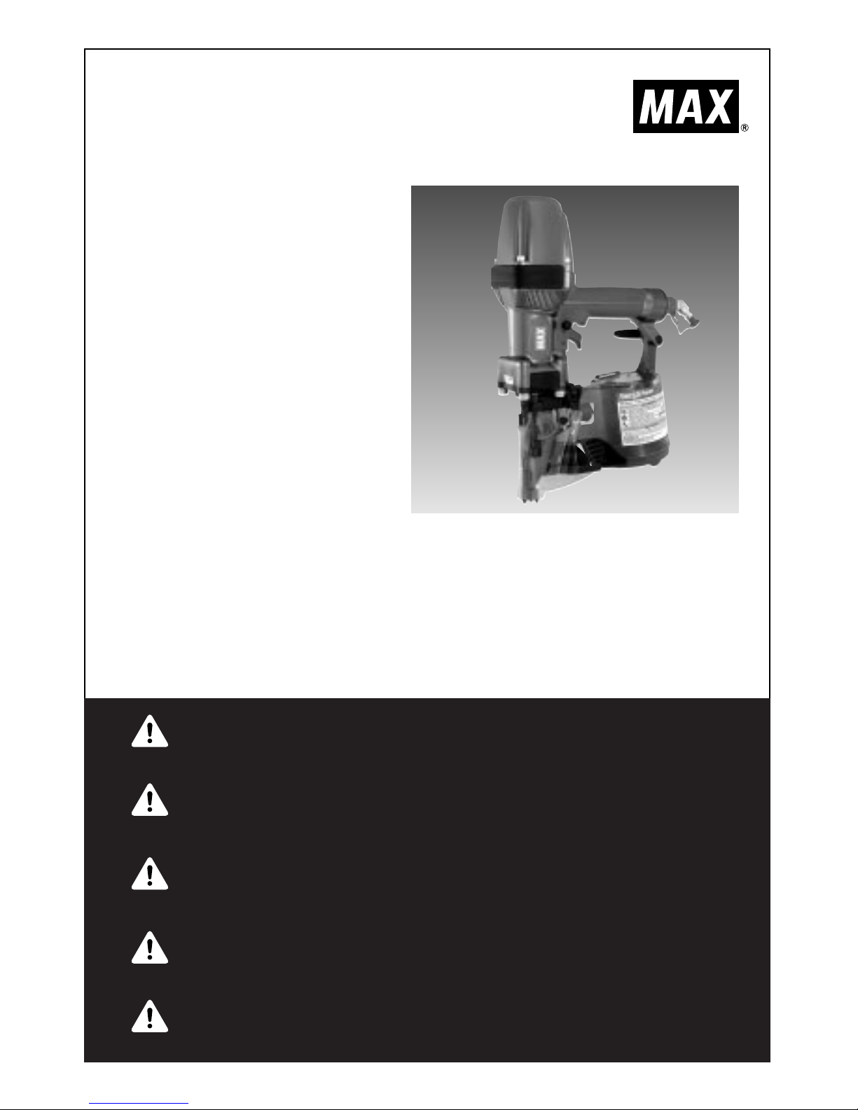
HIGH PRESSURE FRAMING TOOL
HOCHDRUCKGESTALTENWERKZEUG
OUTIL D’ENCADREMENT À HAUTE
PRESSION
ATTREZZO PER INCORNICIATURA AD
ALTA PRESSIONE
HERRAMIENTA DE ENMARCADO DE
ALTA PRESIÓN
OPERATING and MAINTENANCE MANUAL
BETRIEBSANLEITUNG
MANUEL D’UTILISATION et D’ENTRETIEN
MANUALE DI FUNZIONAMENTO E MANUTENZIONE
MANUAL DE OPERACIONES Y MANTENIMIENTO
BEFORE USING THIS TOOL, STUDY THIS MANUAL TO ENSURE SAFETY WARNING AND
INSTRUCTIONS.
KEEP THESE INSTRUCTIONS WITH THE TOOL FOR FUTURE REFERENCE.
WARNING
LESEN SIE VOR INBETRIEBNAHME DES GERÄTES DIE GEBRAUCHS- UND SICHERHEITSHINWEISE. BITTE BEWAHREN SIE DIE GEBRAUCHS- UND SICHERHEITSHINWEISE AUF,
DAMIT SIE AUCH SPÄTER EINGESEHEN WERDEN KÖNNEN.
ACHTUNG
AVANT D’UTILISER CET OUTIL, LIRE CE MANUEL ET LES CONSIGNES DE SECURITE
AFIN DE GARANTIR UN FONCTIONNEMENT SUR.
CONSERVER CE MANUEL EN LIEU SUR AVEC L’OUTIL AFIN DE POUVOIR LE
CONSULTER ULTERIEUREMENT.
AVERTISSEMENT
PRIMA DI USARE QUESTA MACCHINA, STUDIARE IL MANUALE PER PRENDERE ATTO
DEGLI AVVERTIMENTI E DELLE ISTRUZIONIPER LA SICUREZZA.
TENERE QUESTE ISTRUZIONI INSIEME ALLO STRUMENTO PER CONSULTAZIONI FUTURE.
ATTENZIONE
PARA EVITAR GRAVES DAÑOS PERSONALES O EN LA PROPIEDAD.
ANTES DE EMPLEAR LA HERRAMIENTA, LEER CON ATENCIÓN Y COMPRENDER LOS
SIGUIENTES INSTRUCCIONES DE SEGURIDAD.
ATENCIÓN
Page 2

2
DEFINITIONS OF SIGNAL WORDS
WARNING: Indicates a potentially hazardous situation which, if not avoided, could result in death
or serious injury.
CAUTION: Indicates a potentially hazardous situation which, if not avoided, may result in minor or
moderate injury.
NOTE: Emphasizes essential information.
DEFINITIONEN DER HINWEISBEZEICHNUNGEN
ACHTUNG! Zeigt eine eventuell gefährliche Situation an, die den Tod oder schwere Verletzungen
zur Folge haben könnte, wenn sie nicht vermieden wird.
VORSICHT! Zeigt eine eventuell gefährliche Situation an, die leichte oder mittelschwere
Verletzungen zur Folge haben könnte, wenn sie nicht vermieden wird.
HINWEIS: Hebt wichtige Informationen hervor.
DÉFINITIONS DES DIFFÉRENTS DEGRÉS D’ AVERTISSEMENTS
AVERTISSEMENT Indique une situation éventuellement dangereuse qui, si elle n’est pas contournée,
pourrait provoquer la mort ou des blessure sérieuses.
ATTENTION Indique une situation éventuellement dangereuse qui, si elle n’est pas contournée,
pourrait provoquer des blessures légères à moyennement sérieuses.
REMARQUE Souligne des informations importantes.
DEFINIZIONE DELLE INDICAZIONI DI AVVERTIMENTO
ATTENZIONE: Indica l’eventualità che possa verificarsi una situazione pericolosa, la quale se non
viene evitata, può risultare letale o provocare gravi lesioni.
AVVERTENZA: Indica l’eventualità che possa verificarsi una situazione pericolosa, la quale se non
viene evitata, può provocare lesioni di lieve o media entità.
NOTA: Evidenzia informazioni importanti.
DEFINICIÓN DE LAS INDICACIONES DE ADVERTENCIA
¡
ATENCIÓN! Indica una situación potencialmente peligrosa que podría causar la muerte o graves
lesiones si no se evita.
¡
PRECAUCIÓN! Indica una situación potencialmente peligrosa que podría causar lesiones menos
graves o leves si no se evita.
NOTA: Resalta informaciones importantes.
ENGLISH Page 3 to 16 Page
DEUTSCH Page 17 to 30 Page
FRANÇAIS Page 31 to 44 Page
ITALIANO Page 45 to 58 Page
ESPAÑOL Page 59 to 72 Page
INDEX INHALTSVERZEICHNIS INDEX INDICE INDICE
Page 3
3
OPERATING and MAINTENANCE MANUAL
INDEX
1. SAFETY INSTRUCTIONS
…… …… …… …… …… …… …… …… …… …… …… …… …… …… …… ……
3
2. SPECIFICATIONS & TECHNICAL DATA
…… …… …… …… …… …… …… …… …… …… ……
7
3. AIR SUPPLY AND CONNECTIONS
…… …… …… …… …… …… …… …… …… …… …… …… ……
8
4. INSTRUCTIONS FOR OPERATION
…… …… …… …… …… …… …… …… …… …… …… …… ……
10
5. MAINTENANCE
…… …… …… …… ……………………………………………………………………………………
15
6. STORAGE
…… …… …… ……………………………………………………………………………………………………
15
7. TROUBLESHOOTING/REPAIRS
…… …… …… …… …… …… …… …… …… …… …… …… …… ……
15
BEFORE USING THIS TOOL, STUDY THIS MANUAL TO ENSURE SAFETY
WARNING AND INSTRUCTIONS.
KEEP THESE INSTRUCTIONS WITH THE TOOL FOR FUTURE REFERENCE.
WARNING
1. SAFETY INSTRUCTIONS
TO AVOID SEVERE PERSONAL INJURY OR
PROPERTY DAMAGE
BEFORE USING THE TOOL, READ
CAREFULLY AND UNDERSTAND THE
FOLLOWING “SAFETY INSTRUCTIONS”.
FAILURE TO FOLLOW WARNINGS COULD
RESULT IN DEATH OR SERIOUS INJURY.
WARNING
1. WEAR SAFETY GLASSES OR GOGGLES
Danger to the eyes always exists due to the
possibility of dust being blown up by the
exhausted air or of a fastener flying up due to
the improper handling of the tool. For these
reasons, safety glasses or goggles shall
always be worn when operating the tool.
The employer and/or user must ensure that
proper eye protection is worn. Eye protection
equipment must conform to the requirements
of Council Directive 89/686/EEC of 21 DEC.
1989 (the American National Standards
Institute, ANSI Z87.1) and provide both frontal
and side protection.
The employer is responsible to enforce the
use of eye protection equipment by the tool
operator and all other personnel in the work
area.
NOTE: Non-side shielded spectacles and
face shields alone do not provide adequate
protection.
ENGLISH
PRECAUTIONS ON USING THE TOOL
Page 4

ENGLISH
4
2. EAR PROTECTION MAY BE REQUIRED IN
SOME ENVIRONMENTS
As the working condition may include
exposure to high noise levels which can lead
to hearing damage, the employer and user
should ensure that any necessary hearing
protection is provided and used by the
operator and others in the work area.
3. WHEN USING THE TOOL, BE SURE TO
USE A SPECIAL AIR COMPRESSOR AND
AIR HOSE
In order to improve its performance, it has set
its working pressure higher than the
conventional nailers. To use the tool, you
always need the special air compressor and
air hose. Use of combusible pressure gas (for
example, oxygen, acetylene, etc.) causes
abnormal combustion, possibly resulting in
explosion. Use only the special air
compressor and air hose.
4. OPERATE WITHIN THE PROPER AIR
PRESSURE RANGE
The tool is designed to operate within an air
pressure range of 10 to 23 bar (140 to 320
p.s.i.).
The pressure should be adjusted to the type
of the work being fastened. The tool shall
never be operated when the operating
pressure exceeds 23 bar (320 p.s.i.).
5. DO NOT OPERATE THE TOOL NEAR A
FLAMMABLE SUBSTANCE
Never operate the tool near a flammable
substance (e.g., thinner, gasoline, etc.).
Volatile fumes from these substances could
be drawn into the compressor and
compressed together with the air and this
could result in an explosion.
6. NEVER USE THE TOOL IN AN EXPLOSIVE
ATMOSPHERE
Sparks from the tool may ignite atmospheric
gases, dust or other combustible materials.
7. DO NOT USE A WRONG FITTINGS
The connector on the tool must not hold
pressure when air supply is disconnected. If a
wrong fitting is used, the tool can remain
charged with air after disconnecting and thus
will be able to drive a fastener even after the
air line is disconnected, possibly causing
injury.
8. DISCONNECT THE AIR SUPPLY AND
EMPTY THE MAGAZINE WHEN THE TOOL
IS NOT IN USE
Always disconnect the air supply from the tool
and empty the magazine when operation has
been completed or suspended, when
unattended, moving to a different work area,
adjusting, disassembling, or repairing the tool,
and when clearing a jammed fastener.
10bar
140psi
23bar
320psi
Thinner
Gasoline
Page 5
ENGLISH
5
12. USE SPECIFIED FASTENERS
(SEE PAGE 7)
The use of fasteners other than specified
fasteners will cause the tool malfunction. Be
sure to use only specified fasteners when
operating the tool.
13. PLACE THE DISCHARGE OUTLET ON THE
WORK SURFACE PROPERLY
Failure to place the discharge outlet of the
nose in a proper manner can result in a
fastener flying up and is extremely
dangerous.
14. KEEP HANDS AND BODY AWAY FROM
THE DISCHARGE OUTLET
When loading and using the tool, never place
a hand or any part of body in fastener
discharge area of the tool. It is very
dangerous to hit the hands or body by
mistake.
15. DO NOT DRIVE FASTENERS CLOSE TO
THE EDGE AND CORNER OF THE WORK
AND THIN MATERIAL
The workpiece is likely to split and the
fastener could fly free and hit someone.
9. INSPECT SCREW TIGHTNESS
Loose or improperly installed screws or bolts
cause accidents and tool damage when the
tool is put into operation. Inspect to confirm
that all screws and bolts are tight and
properly installed prior to operating the tool.
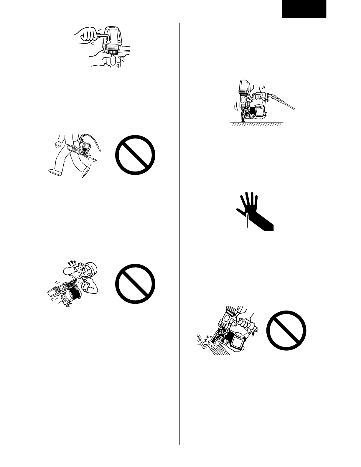
10. DO NOT TOUCH THE TRIGGER UNLESS
YOU INTEND TO DRIVE A FASTENER
Whenever the air supply is connected to the
tool, never touch the trigger unless you intend
to drive a fastener into the work. It is
dangerous to walk around carrying the tool
with the trigger pulled, and this and similar
actions should be avoided.
11. NEVER POINT THE DISCHARGE OUTLET
TOWARD YOURSELF AND OTHER
PERSONNEL
If the discharge outlet is pointed toward
people, serious accidents may be caused
when misfiring. Be sure the discharge outlet
is not pointed toward people when connecting
and disconnecting the hose, loading and
unloading the fasteners or similar operations.
Page 6
ENGLISH
6
20. NEVER USE THE TOOL IF ANY PORTION
OF THE TOOL CONTROLS (e.g., TRIGGER,
CONTACT ARM) IS INOPERABLE,
DISCONNECTED, ALTERED OR NOT
WOKING PROPERLY
21. NEVER ACTUATE THE TOOL INTO FREE
SPACE
This will avoid any hazard caused by free
flying fasteners and excessive strain of the
tool.
22. ALWAYS ASSUME THAT THE TOOL
CONTAINS FASTENERS
23. RESPECT THE TOOL AS A WORKING
IMPLEMENT
24. NO HORSEPLAY
25. NEVER LOAD THE TOOL WITH
FASTENERS WHEN ANY ONE OF THE
OPERATING CONTROLS (e.g., TRIGGER,
CONTACT ARM) IS ACTIVATED
26. WEAR THE GLOVES DEPENDING ON THE
WORKING CONDITION
27. WHEN DISPOSING THE MACHINE OR ITS
PARTS, FOLLOW THE RELEVANT
NATIONAL RULES
OBSERVE THE FOLLOWING GENERAL
CAUTION IN ADDITION TO THE OTHER
WARNINGS CONTAINED IN THIS
MANUAL
• Do not use the tool as a hammer.
• Always carry the tool by the grip, never
carry the tool by the air hose.
• The tool must be used only for the purpose
it was designed.
• Never remove, tamper with the operating
controls (e.g., TRIGGER, CONTACT ARM)
• Keep the tool in a dry place out of reach of
children when not in use.
• Do not use the tool without Safety Warning
label.
• Do not modify the tool from original design
or function without approval by MAX CO.,
LTD.
16. DO NOT DRIVE FASTENERS ON TOP OF
OTHER FASTENERS
Driving fasteners on the top of other fasteners
may cause deflection fasteners which could
cause injury.
17. REMOVING THE FASTENERS AFTER
COMPLETING OPERATION
If fasteners are left in the magazine after the
completion of operation, there is the danger
of a serious accident occurring prior to the
resumption of operation, should the tool be
handled carelessly, or when connecting the
air fitting. For this reason, always remove all
fasteners remaining in the magazine after
completion of the operation.
18. CHECK OPERATION OF THE CONTACT
TRIP MECHANISM FREQUENTLY IN CASE
OF USING A CONTACT TRIP TYPE TOOL
Do not use the tool if the trip is not working
correctly as accidental driving of a fastener
may result. Do not interfere with the proper
operation of the contact trip mechanism.
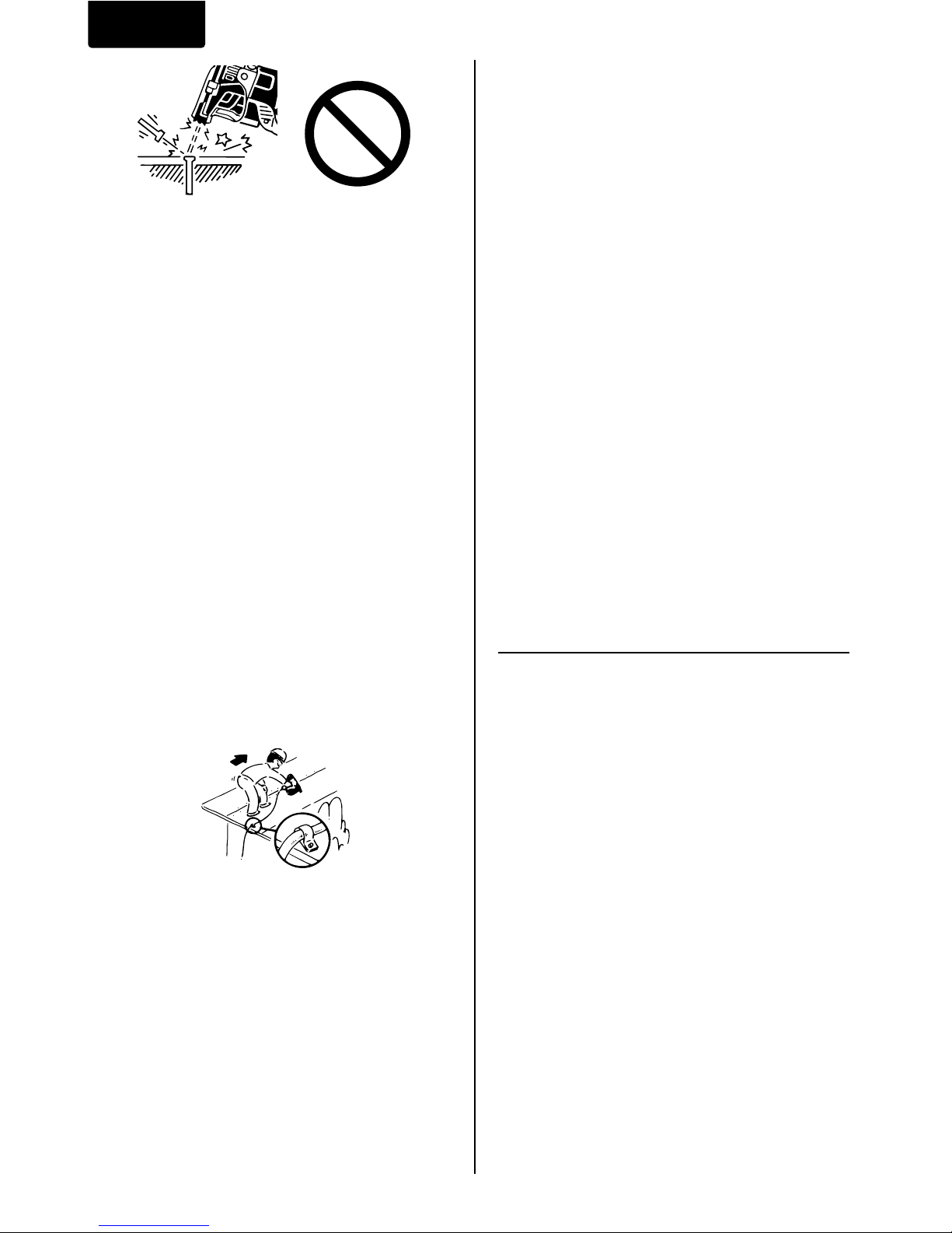
19. WHEN USING THE TOOL OUTSIDE OR
ELEVATED PLACE
When fastening roofs or similar slanted
surface, start fastening at the lower part and
gradually work your way up. Fastening
backward is dangerous as you may lose your
foot place.
Secure the hose at a point close to the area
you are going to drive fasteners. Accidents
may be caused due to the hose being pulled
inadvertently or getting caught.
Page 7
ENGLISH
7
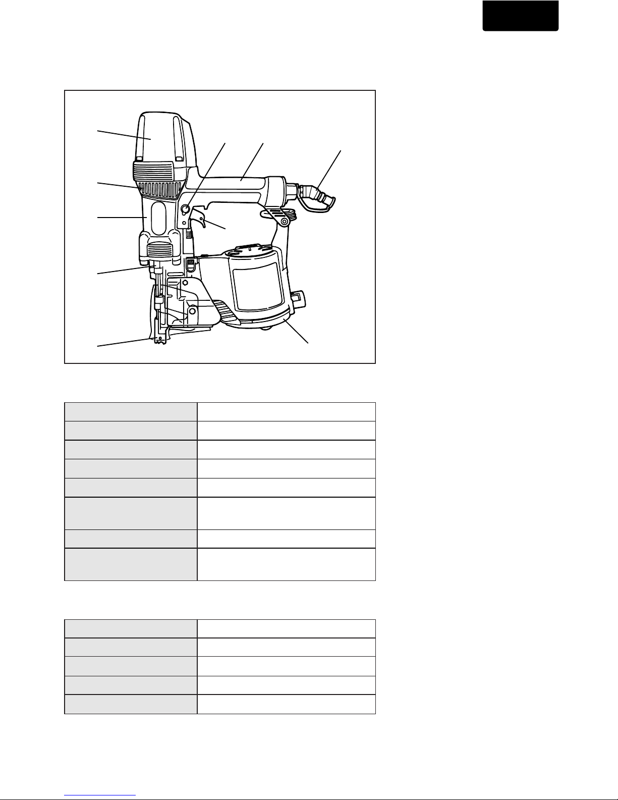
1. NAME OF PARTS
2. TOOL SPECIFICATIONS
3. FASTENER SPECIFICATIONS
i
uo
!0
w
q
r
e
t
y
q
Frame
w
Cylinder Cap
e
Contact Arm
r
Nose
t
Magazine
y
Trigger
u
Grip
i
Exhaust Cover
o
Trigger Lock Dial
!0
Plug
2. SPECIFICATIONS AND TECHNICAL DATA
PRODUCT NO. HN100
HEIGHT 378 mm (14.9”)
WIDTH 117 mm (4.6”)
LENGTH 317 mm (12.5”)
WEIGHT 2.9 kg (6.4 lbs.)
RECOMMENDED
10 to 23 bar (140 to 320 p.s.i.)
OPERATING PRESSURE
LOADING CAPACITY 50 Nails
AIR CONSUMPTION
3.6R at 18 bar (257 p.s.i.)
operating pressure
PRODUCT NO. HN100
NAIL LENGTH 65 to 100 mm (2-1/2” to 4”)
SHANK DIAMETER φ2.9 to φ4.1 mm (.113” to .162”)
SHANK TYPE Smooth, Ring, Screw
HEAD DIAMETER φ7.5 to φ8.4 mm (.295” to .330”)
Page 8

ENGLISH
8
RECOMMENDED OPERATING
PRESSURE:
10 to 23 bar (140 to 320 p.s.i.). Select the
operating air pressure within this range for best
fastener performance.
DO NOT EXCEED 23 bar (320 p.s.i.).
5. APPLICATIONS
*Framing
*Sheathing
*Decking
*Subflooring
*Hard wood
4. TECHNICAL DATA
q NOISE
A-weighted single-event sound power level
------ LWA, 1s, d 92.81 dB
A-weighted single-event emission sound
pressure level at work station
------- LpA, 1s, d 83.35 dB
These values are determined and documented
in accordance to EN12549 : 1999.
w VIBRATION
Vibration characteristic value = 6.6 m/s
2
These values are determined and documented
in accordance to ISO 8662-11.
This value is a tool-related characteristic value
and does not represent the influence to the
hand-arm-system when using the tool. An
influence to the hand-arm-system when using
the tool will, for example, depend on the
gripping force, the contact
pressure force, the working
direction, the adjustment of
mains supply, the workpiece,
the workpiece support.
3. AIR SUPPLY AND
CONNECTIONS
Read section titled “SAFETY
INSTRUCTIONS”.
DO NOT USE ANY POWER SOURCE EXCEPT
AN AIR COMPRESSOR
The tool is designed to operate on compressed
air. Do not operate the tool on any other
combustible gases (e.g., oxygen, acetylene, etc.)
since there is the danger of an explosion. For this
reason, absolutely do not use anything other than
an air compressor to operate the tool.
OPERATE WITHIN THE PROPER AIR
PRESSURE RANGE
The tool is designed to operate within an air
pressure range of 10 to 23 bar (140 to 320 p.s.i.).
The pressure should be adjusted to the type of
the work being fastened. The tool shall never be
operated when the operating pressure exceeds
23 bar (320 p.s.i.).
WARNING
10bar
140psi
23bar
320psi
Page 9

ENGLISH
9
DO NOT OPERATE THE TOOL NEAR A
FLAMMABLE SUBSTANCE
Never operate the tool near a flammable
substance (e.g., thinner, gasoline, etc.). Volatile
fumes from these substances could be drawn into
the compressor and compressed together with
the air and this could result in an explosion.
DO NOT USE A WRONG FITTINGS
The connector on the tool must not hold pressure
when air supply is disconnected. If a wrong fitting
is used, the tool can remain charged with air after
disconnecting and thus will be able to drive a
fastener even after the air line is disconnected,
possibly causing injury.
DISCONNECT THE AIR SUPPLY AND EMPTY
THE MAGAZINE WHEN THE TOOL IS NOT IN
USE
Always disconnect the air supply from the tool
and empty the magazine when operation has
been completed or suspended, when unattended,
moving to a different work area, adjusting,
disassembling, or repairing the tool, and when
clearing a jammed fastener.
WHEN USING THE TOOL, BE SURE TO USE A
SPECIAL AIR COMPRESSOR AND AIR HOSE.
In order to improve its performance, it has set its
working pressure higher than the conventional
nailers. To use the tool, you always need the
special air compressor and air hose (MAX
PowerLite Compressor and MAX PowerLite
Hose). Use of high-pressure gas (for example,
oxygen, acetylene, etc.) causes abnormal
combustion, possibly resulting in explosion. Use
only the special air compressor and air hose.
NOTE:
Frequent, but not excessive, lubrication is
required for the best performance. Oil added thru
the air line connection will lubricate the internal
parts.
Air compressor
[
AIR COMPRESSOR / AIR HOSE
]
Used at 10 to 23 bar (140 to 320 p.s.i.)
10bar
140psi
23bar
320psi
Air hose
Thinner
Gasoline
Page 10

ENGLISH
10
4. INSTRUCTIONS FOR
OPERATION
2. OPERATION
Wear safety glasses or goggles. Danger to the
eyes always exists due to the possibility of dust
being blown up by the exhausted air or of a
fastener flying up due to the improper handling of
the tool. For these reasons, safety glasses or
goggles shall always be worn when operating the
tool.
The employer and/or user must ensure that
proper eye protection is worn. Eye protection
equipment must conform to the requirements of
Council Directive 89/686/EEC of 21 DEC. 1989
(the American National Standards Institute, ANSI
Z87.1) and provide both frontal and side
protection.
The employer is responsible to enforce the use of
eye protection equipment by the tool operator and
all other personnel in the work area.
NOTE: Non-side shielded spectacles and face
shields alone do not provide adequate protection.
WARNING
WARNING
Keep hands and body away from the discharge
outlet when driving the fasteners because of
dangerous of hitting the hands or body by
mistake.
Door Latch
Nail
Feed Pawl
q
Open the Magazine:
Pull up Door Latch and swing Door open.
Swing Magazine Cover open.
NAIL LOADING
w
Nail loading:
Place a coil of nails over the Nail Post in the
Magazine. Uncoil enough nails to reach the
Feed Pawl, and place the second nail between
the teeth on the Feed Pawl. The nail heads fit
in slot on Nose.
Read section titled “SAFETY
INSTRUCTIONS”.
1. BEFORE OPERATION
Check the following prior operation.
q
Wear Safety Glasses or Goggles.
w
Do not connect the air supply.
e
Inspect screw tightness.
r
Check operation of the contact arm & trigger if
moving smoothly.
t
Connect the air supply.
y
Check the air-leakage. (The Tool must not
have the air-leakage.)
u
Hold the Tool with finger-off the trigger, then
push the contact arm against the work-piece.
(The tool must not operate.)
i
Hold the Tool with contact arm free from workpiece and pull the trigger. (The Tool must not
operate.)
o
Disconnect the air supply.
Page 11

ENGLISH
11
e
Swing Magazine Cover closed.
r
Close the Door.
Check that Door Latch engages. (If it does not
engage, check that the nail heads are in the
slot on the Nose).
TEST OPERATION
q
Adjust the air pressure at 10 bar (140 p.s.i.)
and connect the air supply.
w
Without touching the trigger, depress the
contact arm against the work-piece.
Pull the trigger. (The tool must fire the
fastener.)
e
With the tool off the work-piece, pull the
trigger.
Then depress the contact arm against the
work-piece. (The tool must fire the fastener.)
r
Adjust the air pressure as much as the lowest
possible according the length of fastener and
the hardness of work-piece.
MODEL IDENTIFICATION
CONTACT TRIP
The common operating procedure on “Contact
Trip” tools is for the operator to contact the work
to actuate the trip mechanism while keeping the
trigger pulled, thus driving a fastener each time
the work is contacted. This will allow rapid
fastener placement on many jobs, such as
sheathing, decking and pallet assembly.
All pneumatic tools are subject to recoil when
driving fasteners. The tool may bounce, releasing
the trip, and if unintentionally allowed to recontact
the work surface with the trigger still actuated
(finger still holding trigger pulled) an unwanted
second fastener will be driven.
SEQUENTIAL TRIP
The Sequential Trip requires the operator to hold
the tool against the work before pulling the trigger.
This makes accurate fastener placement easier,
for instance on framing, toe nailing and crating
applications. The Sequential Trip allows exact
fastener location without the possibility of driving
a second fastener on recoil, as described under
“Contact Trip”.
The Sequential Trip Tool has a positive safety
advantage because it will not accidentally drive a
fastener if the tool is contacted against the workor anything else-while the operator is holding the
trigger pulled.
SEQUENTIAL TRIP
Identified by ORANGE TRIGGER.
CONTACT TRIP WITH ANTI-DOUBLE FIRE
MECHANISM
(US patent 5597106, UK patent 2286790)
Identified by RED TRIGGER.
Page 12

ENGLISH
12
1
2
DRIVING FASTENERS
CONTACT FIRE OPERATION
(CONTACT TRIP)
For contact fire operation, hold the trigger and
depress the contact arm against the work surface.
PROCEDURE
q
Hold the trigger.
w
Depress the contact arm.
2
1
SINGLE FIRE OPERATION
(ANTI-DOUBLE FIRE MECHANISM AND
SEQUENTIAL TRIP)
For single fire operation, depress the contact arm
against the work surface and pull the trigger. Tool
can not fire a second fastener until the trigger is
released and tool can cycle.
PROCEDURE
q
Depress the contact arm.
w
Pull the trigger.
Adjustment Dial
Contact Arm
ALWAYS disconnect air supply before dial
adjustment.
q
With air pressure set, drive nails into a
representative material sample to determine if
adjustment is necessary.
w
If adjustment is required, disconnect air
supply.
e
Refer to the mark on the Adjust Spacer for
direction to turn the adjustment dial.
r
Reconnect air supply.
WARNING
Trigger lock dial
Trigger
(LOCK)
(UNLOCK)
The tool is equipped with a trigger lock
mechanism. Push and rotate the trigger LOCK to
the trigger UNLOCK position before driving nails.
Deeper Shallow
ADJUSTABLE DIAL DEPTH CONTROL
TRIGGER LOCK MECHANISM
Page 13

ENGLISH
13
Hammer
Contact Tip
Contact Arm
ALWAYS disconnect air supply before
attaching / detaching the contact tip.
Attach the Contact Tip on the tip of Contact Arm,
when driving nails to a soft material.
The Contact Tip can be kept on the Contact Tip
holder when not using.
WARNING
Contact Tip holder
As nails are driven the plastic sheet will feed out
of the tool. When sufficient strip has been fed out
it can be torn away by pulling against the rear
edge in the nose.
When removing jamming of nails, be sure to
lock the trigger prior to disconnecting the air
hose.
PROCEDURE
q
Lock the trigger and disconnect the air hose.
w
Remove the nails out of the magazine.
e
Open the door, put a punch through the
discharge outlet and hit it with a hammer.
WARNING
Punch
r
Remove the nails jamming inside the nose or
contact nose using the punch or a regular
screwdriver.
t
Set the nails properly onto the feed pawl again
and close the door.
Regular screwdriver
CONTACT TIP
HOW TO REMOVE PLASTIC SHEET
HOW TO REMOVE JAMMING OF NAILS
Page 14

ENGLISH
14
WHEN USING THE TOOL FOR STEEL PLATES
●
Carry out work based on the required Work
Standards.
●
If there is no specified work standard, refer
the following as a reference.
●
Never use the nails for the ceilings (ceiling
foundations included) or roofs (roof
foundations included).
●
Be sure to apply discharge outlet to an
object at a right angle.
●
Do not drive the nails into the steel plate
directly.
WARNING
This tool is exclusively designed for 2.3 mm
(.091”) to 3.2 mm (1/8”) thick light gage steel.
When using it, comply with the Work Standards,
considering the object condition and work site
environment.
q
Select appropriate nails according to the
object thickness, seeing the right table.
※ The nails may not be driven into the object
depending on its hardness or thickness.
※ If the object is thinner than an appropriate
range of thickness, the nails may not be driven
into it because of being bent.
Light gage steel:
2.3 mm (.091”) to
3.2 mm (1/8”) thick
Penetration amount
Object thickness
(Total) range
Wood
※
For the 3.2 mm (1/8”) thick light gage steel, use the
φ
2.9〜3.4 mm (.113”〜.134”) nails for steel plates.
w
If the thickness of the light gauge steel
foundations material used is 3.2 mm (1/8”),
use the φ2.9〜3.4 mm (.113”〜.134”) nails for
steel plate.
e
Never drive the nails directly into the light
gauge steel because they will fly off,
endangering you.
r
Be sure to apply the discharge outlet to the
object at a right angle. If applied obliquely, the
nails will fly off, endangering you.
t
Never use the nails for the roofs (roof
foundations included) or ceilings (ceiling
foundations included).
y
If the nails are driven into the steel plate too
deeply, their holding force will be extremely
reduced. When working with the tool, fully
check the driven conditions.
Page 15

ENGLISH
15
5. MAINTENANCE
w
DO NOT FIRE THE NAILER WHEN IT IS
EMPTY
e
USE RECOMMENDED OIL
The velocite or turbine oil should be used to
lubricate the tool. Upon completion of
operations, place 5 or 6 drops of oil into the air
plug inlet with the jet oiler. (Recommended Oil
: ISO VG32)
r
INSPECT AND MAINTAIN DAILY OR
BEFORE OPERATION
6. STORAGE
q
When not in use for an extended period, apply
a thin coat of the lubricant to the steel parts to
avoid rust.
w
Do not store the tool in a cold weather
environment. Keep the tool in a warm area.
e
When not in use, the tool should be stored in a
warm and dry place. Keep out of reach of
children.
r
All quality tools will eventually require servicing
or replacement of parts because of wear from
the normal use.
7. TROUBLE
SHOOTING/REPAIRS
The troubleshooting and/or repairs shall be
carried out only by the MAX CO., LTD. authorised
distributors or by other specialists.
WARNING
Disconnect air supply and empty the
magazine when inspecting or maintaining the
tool.
(1) Tighten all screws
(2) Keep contact arm moving smoothly
q
ABOUT PRODUCTION YEAR
This product bears production number at the
lower part of the grip of the main body. The
two digits of the number from left indicates the
production year.
(Example)
0 8 8 2 6 0 3 5 D
Year 2008
Page 16

ENGLISH
16
Supplement to the operating instruction
According to the European Norm EN 792-13 the
regulation is valid from 01.01.2001 that all
fastener driving tools with contact actuation must
be marked with the symbol “Do not use on
scaffoldings, ladders” and they shall not be used
for specific application for example:
*when changing one driving location to another
involves the use of scaffoldings, stairs, ladders
or ladder alike constructions e.g. roof laths,
*closing boxes or crates,
*fitting transportation safety systems e.g. on
vehicles and wagons.
Page 17

73
109
O-RING KIT
Parts marked
are included
in the O-ring kit
69
71
29
20
25
53
33
67
24
26
25
28
113
31
35
34
40
70
32
32
19
2
27
3
4
14
15
66
9
12
118
6
5
6
7
6
21
22
6
52
42
49
116
117
43
48
43
44
45
47
72
73
75
74
88
87
76
91
103
89
81
82
94
84
85
65
112
51
6
41
46
50
114
A
B
68
A
23
83
1
8
10
11
13
16
17
18
105
111
36
37
38
39
86
93
92
70
104
95
100
115
B
99
90
97
98
96
57
60
58
59
61
62
63
64
54
95
96
108
107
106
102
101
101
110
125
124
55
121
126
122
123
79
78
77
70
80
55
EXPLODED
VIEW AND SPARE
PARTS LIST
EINZELTEILDAR-
STELLUNG UND
ERSATZEILLISTE
SCHEMA ECLATE ET
LISTE DES PIECEC
DE RECHANGE
ESPLOSO DEI
COMPONENTI DE
ELENCO DELLE
PARTI DI RICAMBIO
DESPIECE DE LA
MAQUINA Y LISTA
DE RECAMBIOS
HN100
PNEUMATIC STAPLER
Page 18

74
HN100
ESPAÑOLITALIANOFRANÇAISENGLISHMATERIAL DEUTSCH
ITEM
NO.
PART
NO.
1
2
3
4
5
6
7
8
9
10
11
12
13
14
15
16
17
18
19
20
21
22
23
24
25
26
27
28
29
30
31
32
33
34
35
36
37
38
39
40
41
42
43
44
45
46
47
48
49
50
51
52
53
54
55
56
57
58
59
HN10067 Steel SCREW 6X35 SCHRAUBE 6X35 VIS 6X35 VITE 6x35 TORNILLO 6x35
HN10064 Magnesium CYLINDER CAP ZYLINDERDECKEL
COUVERCLE DE CYLINDRE
COPERCHIO CILINDRO CUBIERTA DE CILINDRO
HN10068 Magnesium INNER CAP INNEREKAPPE CAPOT INTÉRIEURE CAPPUCCIO INTERNA CAPERUZA INTERNO
KK23650 Stainless steel
COMPRESSION SPRING 3650
DRUCKFEDER 3650
RESSORT À PRESSION 3650
MOLLA DI COMPRESSIONE 3650 MUELLE DE COMPRESIÓN 3650
HN10072 Urethane PISTON STOP KOLBENANSCHLAG BUTÉE DE PISTON FERMO STANTUFFO TOPE ÉMBOLO
HH19127 Rubber O-RING 1A 1.5X6.6 O-RING 1A 1.5X6.6
JOINT TORIQUE 1A 1.5X6.6
O-RING 1A 1.5X6.6
ANILLO TÓRICO 1A 1.5X6.6
HN10069 Aluminum PIPE ROHR TUYAU TUBO TUBO
HH19216 Rubber O-RING 1B 2.6X37.7 O-RING 1B 2.6X37.7
JOINT TORIQUE 1B 2.6X37.7
O-RING 1B 2.6X37.7
ANILLO TÓPRICO 1B 2.6X37.7
HN10070 Polyacetal HEAD VALVE PISTON KOPFVENTILKOLBEN
PISTON DE CLAPET DE TÉTE
STANTUFFO VALVOLA DI MANDATA
EMBORO VÁLVULA DEL CABEZAL
HH11156 Rubber O-RING AS568-137 O-RING AS568-137
JOINT TORIQUE AS568-137
O-RING AS568-137
ANILLO TÓRICO AS568-137
HH11157 Rubber O-RING AS568-136 O-RING AS568-136
JOINT TORIQUE AS568-136
O-RING AS568-136
ANILLO TÉRICO AS568-136
HN10071 Aluminum HEAD VALVE GUIDE DRUCKVENTILFÜHRER
GUIDE DE CLAPET DE TÊTE
GUÍA DE LA VÁLVULA DEL CABEZAL
HH19138 Rubber O-RING 1A 1.8X58.5 O-RING 1A 1.8X58.5
JOINT TORIQUE 1A 1.8X58.5
O-RING 1A 1.8X58.5
ANILLO TÓRICO 1A 1.8X58.5
HN10076 Urethane CYLINDER SEAL ZYLINDERDICHTUNG JOINT DE CYLINDRE
GUARNIZIONE DEL CILINDRO
SELLO DEL CILINDRO
HN10077 Aluminum CYLINDER ZILINDER CYLINDRE CILINDRO CILINDRO
HH19178 Rubber O-RING 1A 3.1X47.4 O-RING 1A 3.1X47.4
JOINT TORIQUE 1A 3.1X47.4
O-RING 1A 3.1X47.4
ANILLO TÓRICO 1A 3.1X47.4
HH11146 Rubber O-RING AS568-128 O-RING AS568-128
JOINT TORIQUE AS568-128
O-RING AS568-128
ANILLO TÓRICO AS568-128
HH11806 Urethane O-RING P27 O-RING P27 JOINT TORIQUE P27 O-RING P27 ANILLO TÉRICO P27
HN10073 Magnesium, Steel MAIN PISTON UNIT ARBEITSKOLBEN KOMPL
PISTON DE TRAVAIL COMPLET
GRUPPO STANTUFFO OPERATORE
EMBORO DE TRAVAJO COMPL.
HN10106 Nylon, Rubber EXHAUST COVER UNIT ABSAUGHAUBEKOMPL
CAPOT D'ASPIRATION COMPLET
CAMPANA DE ASPIRACIÓN COMP.
HN10097 Polyacetal FILTER B FILTER B FILTRE B FILTRO B FILTRO B
HN10096 Stainless steel FILTER A FILTER A FILTRE A FILTRO A FILTRO A
HN81026 Magnesium FRAME ASSY GEHÄUSE KOMPL BOÎTIER COMPLET
GRUPPO ALLOGGIAMENTO
CARCASA COMP
CN34309
Polyethylene terephthalate
COUPLING CAUTION SEAL
KOPPELUNGSVORSICHTSSCHILD
HN11741
Polyethylene terephthalate
LOGO SEAL LOGOSIEGEL SCEAU LOGO SIGILLO LOGO SELLO LOGO
FF21201 Steel ROLL PIN 2.5X10 ROLLENBOLZEN 2.5X10
TOURILLON DE CYLINDRE 2.5X10
PERNO DI ROTOLAMENT 2.5X10
PERNO DE RODILLO 2.5X10
HN10327 Nylon TRIGGER LOCK DIAL
BETÄTIGUNGSSPERREKNOPF DISCO DI SICURA GRILLETTO
KK23507 Stainless steel
COMPRESSION SPRING 3507
DRUCKFEDER 3507
RESSORT À PRESSION 3507
MOLLA DI COMPRESSIONE 3507 MUELLE DE COMPRESIÓN 3507
FF21235 Steel ROLL PIN 3X30 ROLLENBOLZEN 3X30
TOURILLON DE CYLINDRE 3X30
PERNO DI ROTOLAMENT 3X30
PERNO DE RODILLO 3X30
CN34699 Nylon TRIGGER LOCK LEVER
BETÄTIGUNGSSPERREHEBEL LEVA DI SICURA GRILLETTO
HN10087 Rubber PROTECTOR A
SCHUTZVORRICHTUNG A
DISPOSITIF DE PROTECTION A
DISPOSITIVO DI PROTEZIONE A DISPOSITIVO DE PROTECCIÓN A
HN10050 Rubber GRIP COVER A GRIFFBELAG A
RÊVETEMENT DE POIGNÉE A
REVESTIMIENTO DE SUJECIÓN A
HN10051 Rubber GRIP COVER B GRIFFBELAG B
RÊVETEMENT DE POIGNÉE B
REVESTIMIENTO DE SUJECIÓN B
BB40437 Steel SCREW 5X30 SCHRAUBE 5X30 VIS 5X30 VITE 5X30 TORNILLO 5X30
HH12118 Rubber O-RING 1A G35 O-RING 1A G35 JOINT TORIQUE 1A G35 O-RING 1A G35 ANILLO TÓRICO 1A G35
HN10313 Magnesium END CAP ABSCHLUSSKAPPE
CAPOT DE RECOUVREMENT
CAPPUCCIO DI CHIUSURA
CAPERUZA DE CIERRE
HN10316 Vinyl acetate END PLUG CAP ENDENSTECKERKAPPE
CAPOT DE PRISE D'EXTRÉMITÉ
TT05425 Steel AIR PLUG H-FPM LUFTSTECKER H-FPM PRISE D'AIR H-FPM
PRESA DELL'ARIA H-FPM
ENCHUFE DEL AIRE H-FPM
HH12904 Rubber O-RING 1A 1X6.2 O-RING 1A 1X6.2 JOINT TORIQUE 1A 1X6.2 O-RING 1A 1X6.2
ANILLO TÓRICO 1A 1X6.2
HN10043 Steel PILOT CAP STEUERVENTILSKAPPE CAPOT VANNE-PILOTE
HN10018 Urethane PILOT SEAL
STEUERVENTILSDICHTUNG
JOINT VANNE-PILOTE
SELLO DE VALVULA DE CONTROL
HH12105 Rubber O-RING 1A 1.5X12.8 O-RING 1A 1.5X12.8
JOINT TORIQUE 1A 1.5X12.8
O-RING 1A 1.5X12.8
ANILLO TÓRICO 1A 1.5X12.8
HN10016 Polyacetal
TRIGGER VALVE HOUSING
BETÄTIGUNGSVENTILGEHÄUSE
HH11208 Rubber O-RING 1B P6 O-RING 1B P6 JOINT TORIQUE 1B P6 O-RING 1B P6 ANILLO TÓRICO 1B P6
HN80049 PILOT VALVE ASSY STEUERVENTIL KOMPL
VANNE-PILOTE COMPLET
VÀLVULA DE CONTROL COMP
HH11132 Rubber O-RING 1A P10A O-RING 1A P10A JOINT TORIQUE 1A P10A O-RING 1A P10A ANILLO TÓRICO 1A P10A
KK23619 Stainless steel
COMPRESSION SPRING 3619
DRUCKFEDER 3619
RESSORT À PRESSION 3619
MOLLA DI COMPRESSIONE 3619 MUELLE DE COMPRESIÓN 3619
HH19707 Rubber O-RING 1A 1.4X2.5 O-RING 1A 1.4X2.5
JOINT TORIQUE 1A 1.4X2.5
O-RING 1A 1.4X2.5
ANILLO TÓRICO 1A 1.4X2.5
HN80023 TRIGGER VALVE ASSY
BETÄTIGUNGSVENTILAUFBAU
HH19214 Rubber O-RING 1B 1.5X3 O-RING 1B 1.5X3
JOINT TORIQUE 1B 1.5X3
O-RING 1B 1.5X3
ANILLO TÓRICO 1B 1.5X3
HN10019 Steel TRIGGER VALVE CAP
BETÄTIGUNGSVENTILDECKEL
KK33237 Stainless steel TORSION SPRING 3237 TORSIONSFEDER 3237
RESSORT DE TORSION 3237
MOLLA DI TORSIONE 3237 MUELLE DE TORSIÓN 3237
HN10104 Steel CONTCT LEVER KONTAKTHEBEL LEVIER DE CONTACT LEVA DI CONTATTO PALANCA DE CONTACTO
FF22402 Stainless steel ROLL PIN 3X16 ROLLENBOLZEN 3X16
TOURILLON DE CYLINDRE 3X16
PERNO DI ROTOLAMENT 3X16
PERNO DE RODILLO 3X16
HN80037 TRIGGER ASSY
BETÄTIGUNGSHEBEL KOMPL.
LEVIER DE COMMANDE COMPLET
UNITÀ DEL GRILLETTO
CN34800 Nylon SWITCH LEVER FAHRSCHALTHEBEL
LEVIER D'INTERRUPTEUR
LEVA DELL'INTERRUTTORE PALANCA DEL INTERUPTOR
CN34500 Stainless steel SWITCH SPRING SCHALTERFEDER
RESSORT D'INTERRUPTEUR
MOLLA DELL'INTERRUTTORE
MUELLE DEL INTERRUPTOR
HN10022 Steel CONTACT ARM A KONTAKTARM A BARRE DE CONTACT A
BRACCIO DI CONTATTO A
BRAZO DE CONTACTO A
GUIDA DELLA VALVOLA A
BATTENTE
ÉTIQUETTE DE PRECAUTION
D'ACCOUPLEMENT
ETICHETTA DI PRECAUZIONE
DELL'ACCOPPIAMENTO
UNITÀ DEL COPERCHIO DELLO
SCARIO
ETIQUETA DE PRECAUCIÓN
DEL ACOPLADOR
DISQUE DE BLOCAGE
DE LA COMMANDE
DISCO, BLOQUE
DE ACCIONAMIENTO
LEVIER DE BLOCAGE
DE LA COMMANDE
PALANCA, BLOQUEO
DE ACCIONAMIENTO
RIVESTIMENTO DI
IMPUGNATURA A
RIVESTIMENTO DI
IMPUGNATURA B
CAPERUZA DEL ENCHUFE
DE EXTREMIDAD
CAPPUCCIO DI PRESA
D'ESTREMITA
CAPERUZA DE VALVULA DE
CONTROL
PROTEZIONE VALVOLA DI
COMANDO
GUARNIZIONE VALVOLA DI
COMANDO
CARTER DE SOUPAPE
DE DÉCLENCHEMENT
ALLOGGIO DELLA VALVOLA
DI INNESCO
UNITÀ DELLA VALVOLA DI
COMANDO
CUBIERTA DE VÁLVULA
DEL DISPARADOR
ENSEMBLE DE SOUPAPE
DE COMMANDE
CONJUNTO VÁLVULA
DE ACCIONAMIENTO
GRUPPO VALVOLA DI
AZIONAMENTO
CAPUCHON DE SOUPAPE
DE COMMANDE
COPERCHIO VALVOLA
DI AZIONAMENTO
CAPERUZA VÁLVULA
DE ACCIONAMIENTO
PALANCA DE ACCIONAMIENTO
COMP
Page 19

75
HN100
ESPAÑOLITALIANOFRANÇAISENGLISHMATERIAL DEUTSCH
ITEM
NO.
PART
NO.
60
61
62
63
64
65
66
67
68
69
70
71
72
73
74
75
76
77
78
79
80
81
82
83
84
85
86
87
88
89
90
91
92
93
94
95
96
97
98
99
100
101
102
103
104
105
106
107
108
109
110
111
112
113
114
115
116
117
118
ANILLO DE RETENCIÓN EN C 24
SUS
ANELLO DI RITEGNO E 3.2
(BASTONE)
ZUFUHRSPERRKLINKENABDECKUNG
HN10021 Steel ARM GUIDE ARMFÜHRER
GUIDE DE BRAS DE CONTACT
GUIDA DEL BRACCIO DI CONTATTO
GUÌA DEL BRAZO
KK23620 Stainless steel
COMPRESSION SPRING 3620
DRUCKFEDER 3620
RESSORT À PRESSION 3620
MOLLA DI COMPRESSIONE 3620 MUELLE DE COMPRESIÓN 3620
HN10041 Rubber CONTACT BUMPER
KONTAKTSTOSSDÄNPFER
AMORTISSEUR DE CONTACT
AMMORTIZZATORE DI CONTATTO
AMORTIGUADOR DE CONTACTO
HN10042 Steel CONTACT COLLAR KONTAKTSTELLRING COLLIER DE CONTACT COLLARE DI CONTATTO COLLAR DE CONTACTO
HN10026 Polyacetal ADJUST DIAL
EINSTELLVORWAHLKNOPF
CADRAN DE RÉGLAGE
MANOPOLA DI REGOLAZIONE
CUADRANTE DE AJUSTE
HN10082 Polyacetal ADJUST SPACER
EINSTELLDISTANZSCHEIBE
ENTRETOISE DE RÉGLAGE
DISTANZIATORE DI REGOLAZIONE
ESPACIADOR DE AJUSTE
HN10078 Rubber BUMPER STOSSDÄMPFER AMORTISSEUR AMMORTIZZATORE AMORTIGUADOR
HH19168 Rubber O-RING 1A 1.5X44 O-RING 1A 1.5X44
JOINT TORIQUE 1A 1.5X44
O-RING 1A 1.5X44
ANILLO TÓRICO 1A 1.5X44
HN10081 Steel NOZE NAGLERNASE NEZ DE CLOUEUR PUNTA SPARACHIODI NARIZ
BB40206 Steel SCREW 8x30 SCHRAUBE 8x30 VIS 8x30 VITE 8x30 TORNILLO 8x30
EE39602 Urethane RUBBER WASHER 7 GUMMISCHEIBE 7
DISQUE DE CAOUTCHOUC 7
RONDELLA IN GOMMA 7
ARANDELO DE CAUCHO 7
FF41599 Steel STEP PIN 1599 STUFENBOLZEN 1599
BOULON À GRADINS 1599
PERNO SCALARE 1599
PERNO ESCALONADO 1599
KK33261 Stainless steel TORSION SPRING 3261 TORSIONSFEDER 3261
RESSORT DE TORSION 3261
MOLLA DI TORSIONE 3261 MUELLE DE TORSIÓN 3261
CN33679 Steel DOOR LATCH TÜRVERSCHLUSS FERMETURE DE PORTE CHISURA SPORTELLO CIERRE PUERTA
HN10085 Steel DOOR TÜR PORTE SPORTELLO PUERTA
EE39609 Urethane
RUBBER WASHER 1.8X6X2
GUMMISCHEIBE 1.8X6X2
DISQUE DE CAOUTCHOUC 1.8X6X2
RONDELLA IN GOMMA 1.8X6X2 ARANDELO DE CAUCHO 1.8X6X2
FF31520 Steel PARALLEL PIN 1520 PARALLELBOLZEN 1520
GOUPILLE PARALLELE 1520
PERNO PARALLELO 1520
PERNO PARALELO 1520
HN10083 Steel FEED PAWL VORSCHUBKLINKE CLIQUET D'AVANCE
NOTTOLINO DI AVANZAMENTO
TRINQUETE DE AVANCE
FF41509 Steel STEP PIN 1509 STUFENBOLZEN 1509
BOULON À GRADINS 1509
PERNO SCALARE 1509
PERNO ESCALONADO 1509
KK23573 Stainless steel
COMPRESSION SPRING 3573
DRUCKFEDER 3573
RESSORT À PRESSION 3573
MOLLA DI COMPRESSIONE 3573 MUELLE DE COMPRESIÓN 3573
HH11113 Rubber O-RING 1A P9 O-RING 1A P9 JOINT TORIQUE 1A P9 O-RING 1A P9 ANILLO TÓRICO 1A P9
HN10084 Steel FEED PISTON VORSCHUBKOLBEN PISTON D'AVANCE
STANTUFFO DI AVANZAMENTO
EMBOLO DE AVANCE
HH11106 Rubber O-RING 1A P16 O-RING 1A P16 JOINT TORIQUE 1A P16 O-RING 1A P16 ANILLO TÓRICO 1A P16
KK23173 Stainless steel
COMPRESSION SPRING 3173
DRUCKFEDER 3173
RESSORT À PRESSION 3173
MOLLA DI COMPRESSIONE 3173 MUELLE DE COMPRESIÓN 3173
CN32093 Urethane FEED PISTON STOP
VORSCHUBKOLBENSCHLAG BUTÉE DE PISTON D'AVANCE
TOPE ÉMBOLO DE AVANCE
HN10388 Steel SPRING COLLAR FEDERSSTELLRING COLLIER DE RESSORT COLLARE DELLA MOLLA COLLAR DE MUELLE
JJ22408 Stainless steel
C-RETAINING RING 24 SUS
C-HALTERING 24 SUS
BAGUE DE RETENUE C 24 SUS ANELLO DI RITEGNO C 24 SUS
HN10027 Steel CONTACT BOLT
KONTAKTSCHRAUBBOLZEN
BOULON DE CONTACT BULLONE DI CONTATTO PERNO DE CONTACTO
JJ10404 Stainless steel
E-RETAINING RING 3.2 (STICK)
E-HALTERING 3.2 (STOCK)
BAGUE DE RETENUE E 3.2 (BÂTON)
HN10109 Steel CONTACT ARM B UNIT KONTACTARM B KOPML
BARRE DE CONTACT B COMPLET
GRUPPO BRACCIO DI CONTATTO B
BRAZO DE CONTACTO B COMPL
HN11602 Urethane CONTACT TIP KONTAKTKAPPE CAPUCHON DE CONTACT
COPERCHIO DI CONTATTO CAPERUZA DE CONTACTO
BB40428 Steel SCREW 6X25 SCHRAUBE 6X25 VIS 6X25 VITE 6X25 TORNILLO 6X25
HN10086 Nylon FEED PAWL COVER
CC49406 Steel, Nylon NUT 406 MUTTER 406 ECROU 406 DADO 406 TUERCA 406
KK23627 Stainless steel
COMPRESSION SPRING 3627
DRUCKFEDER 3627
RESSORT À PRESSION 3627
MOLLA DI COMPRESSIONE 3627 MUELLE DE COMPRESIÓN 3627
HN10089 Polycarbonate MAGAZINE CAP MAGAZINKAPPE CAPOT DE MAGASIN
CAPPUCCIO DEL CARICATORE
CAPERUZA DEL CARGADOR
HN11742
Polyethylene terephthalate
NAME SEAL NAMENSDICHTUNG SCEAU DU NOM SIGILLO DEL NOME SELLO DEL NOMBRE
DUM0000 Steel, Nylon NUT M5 MUTTER M5 ECROU M5 DADO M5 TUERCA M5
HN10003 Nylon HOOK HAKEN CROCHET GANCIO GANCHO
HN10088 Nylon MAGAZINE MAGAZIN MAGASIN CARICATORE CARGADOR
FF31254 Steel PARALLEL PIN 1254 PARALLELBOLZEN 1254
GOUPILLE PARALLELE 1254
PERNO PARALLELO 1254
PERNO PARALELO 1254
CN31083 Rubber DUST COVER FITTING
SCHUTZABDECKUNGSBEFESTIGUNG
HN10090 Polyvinyl chloride DUST COVER STAUBDECKEL
COUVERCLE ANTI-POUSSIERE
COPERCHIO PARAPOLVERE
TAPA GUARDAPOLVO
HH11903 Rubber O-RING 1A 1.2X4 O-RING 1A 1.2X4 JOINT TORIQUE 1A 1.2X4 O-RING 1A 1.2X4
ANILLO TÓRICO 1A 1.2X4
HN10102 Steel NEEDLE POINT GUIDE A NADELPUNKTFÜHRER A
GUIDE DE POINT D'AIGUILLE A
GUIDA DI PUNTO D'AGO A
GUÍA DE PUNTO DE AGUJA A
HN81185 MAGAZINE CAP ASSY MAGAZINKAPPE KOMPL
CAPOT DE MAGASIN COMPLET
HN11744 Steel FRAME HANGER GEHÄUSEAUFHÄNGER SUPPORT DE BOÎTIER
SUPPORTO DI ALLOGGIAMENTO
SUSPENSIÓN DE CARCASA
HS10704 Steel SCREW 6X38 SCHRAUBE 6X38 VIS 6X38 VITE 6X38 TORNILLO 6X38
HN81188 FRAME HANGER KIT
GEHÄUSEAUFHÄNGERSKIT
KIT DE SUPPORT DE BOÎTIER
KIT DE SUSPENSIÓN DE CARCASA
HN81187 O-RING KIT ASSY
O-RING-KIT-VERSAMMLUNG ENSEMBLE DE KIT DE BAGUE
INSIEME DI KIT D'ANELLO
CONJUNTO DE KIT DE ANILLO “O”
HN81186 DS KIT ASSY DS-INSTALLATIONSKIT ENSEMBLE DE KIT DS INSIEME DEL KIT DS
CONJUNTO DE EQUIPO DS
TA17024 Nylon END CAP FILTER KM-23
ABSCHLUSSKAPPEFILTER KM-23
HN81190 ARM GUIDE KIT ARMFÜHRERSKIT KIT DE GUIDE DE BRAS
KIT DELLA GUIDA BRACCIO KIT DE LA GUÍA DEL BRAZO
HN10757
Polyethylene terephthalate
TRIGGER LOCK SEAL
BETÄTIGUNGSSPERREDICHTUNG
HN81189 TRIGGER VALVE KIT BETÄTIGUNGSVENTILKIT
KIT DELLA VALVOLA DI INNESCO
HN70226 MAGAZINE MODULE MAGAZIN-MODUL MODULE DU MAGASIN
MODULO DEL MAGAZZINO
MÓDULO DEL CARGADOR
HN10017 Polyacetal PILOT VALVE STEUERVENTIL VANNE-PILOTE VALVOLA DI COMANDO VÁLVULA DE CONTROL
HN10057 Steel TRIGGER VALVE STEM
BETÄTIGUNGSVENTILSCHAFT
TIGE DE SOUPAPE DE COMMANDE STELO VALVOLA DI AZIONAMENTO
CN34494 Polyacetal TRIGGER BETÄTIGUNGSHEBEL LEVIER DE COMMANDE GRILLETTO
PALANCA DE ACCIONAMIENTO
FERMO STANTUFFO DI
AVANZAMENTO
ANILLO DE RETENCIÓN EN E 3.2
(PALILLO)
AJUSTAGE DE COUVERCLE
ANTI-POUSSIÉRE
MONTAGGIO DEL COPERCHIO
ANTIPOLVERE
GUARNICIÓN DE TAPA
GUARDAPOLVO
GRUPPO DI CAPPUCCIO DEL
CARICATORE
KIT DI SUPPORTO DI
ALLOGGIAMENTO
CAPERUZA DEL CARGADOR
COMPL
FILTRE KM-23 DE CAPOT DE
RECOUVREMENT
FILTRO DE CAPERUZA DE
CIERRE KM-23
FILTRO DEL CAPPUCCIO DI
CHIUSURA KM-23
JOINT DE BLOCAGE DE
DÉCLENCHEMENT
GUARNIZIONE DI BLOCCAGGIO
DI INNESCO
SELLO DE BLOQUEO DEL
DISPARADOR
KIT DE LA VÁLVULA DEL
DISPARADOR
KIT DE SOUPAPE DE
DÉCLENCHEMENT
VÁSTAGO VÁLVULADE
ACCIONAMIENTO
COUVERCLE DU CLIQUET
D’AVANCEMENT
COPERCHIO DEL DENTE
D'ARRESTO DI AVANZAMENTO
CUBIERTA DEL TRINQUETE
DE AVANCE
Page 20

76
HN100
ESPAÑOLITALIANOFRANÇAISENGLISHMATERIAL DEUTSCH
ITEM
NO.
PART
NO.
119
120
121
122
123
124
125
126
CN35260 Polyacetal TRIGGER BETÄTIGUNGSHEBEL LEVIER DE COMMANDE GRILLETTO
PALANCA DE ACCIONAMIENTO
HN10100 Steel CONTCT LEVER KONTAKTHEBEL LEVIER DE CONTACT LEVA DI CONTATTO PALANCA DE CONTACTO
HN10101 Steel CONTACT ARM A KONTAKTARM A BARRE DE CONTACT A
BRACCIO DI CONTATTO A
BRAZO DE CONTACTO A
HN10103 Steel CONTACT COLLAR KONTAKTSTELLRING COLLIER DE CONTACT COLLARE DI CONTATTO COLLAR DE CONTACTO
KK23902 Stainless steel
COMPRESSION SPRING 3902
DRUCKFEDER 3902
RESSORT À PRESSION 3902
MOLLA DI COMPRESSIONE 3902 MUELLE DE COMPRESIÓN 3902
KK33346 Stainless steel TORSION SPRING 3346 TORSIONSFEDER 3346
RESSORT DE TORSION 3346
MOLLA DI TORSIONE 3346 MUELLE DE TORSIÓN 3346
Page 21

Recycled paper is used for this manual and its recyclable.
www.max-ltd.co.jp/int/ (GLOBAL Site)
www.max-europe.com (EUROPE Site)
★
080313-00/01
OSTSTRASSE 22, 40211
DÜSSELDORF, GERMANY
TEL: +49-211-9365300
FAX: +49-211-93653017
Camerastraat 19
1322 BB Almere The Netherlands
Phone: +31-36-546-9699
FAX: +31-36-536-3985
PRINTED IN JAPAN GEDRUCKT IN JAPAN IMPRIMÉ AU JAPON STAMPATO IN GIAPPONE IMPRESO EN JAPÓN
• The content of this manual might be changed without notice for improvement.
• Änderungen der Betriebsanleitung zum Zwecke der Verbesserung ohne Ankündigung
vorbehalten.
• Le contenu de ce manuel est sujet à modification sans préavis à des fins
d’amélioration.
•I contenuti di questo manuale possono essere cambiati senza preavviso per motivi di
miglioramento del prodotto.
• El contenido de este manual puede ser cambiado sin noticia previa para mejoramiento.
•
The specifications and design of the products in this manual will be subject to change without
advance notice due to our continuous efforts to improve the quality of our products.
•
Änderungen bei technischen Daten und Design der Produkte in diesem Handbuch im Sinne der
Produktverbesserung bleiben vorbehalten.
•
Les caractéristiques et la conception des produits mentionnés dans ce manuel sont sujettes à
des modifications sans préavis en raison de nos efforts continus pour améliorer la qualité de nos
produits.
•
Le caratteristiche e la concezione dei prodotti menzionati in questo manuale sono soggette a
modifiche senza preavviso a causa dei nostri sforzi continui per migliorare la qualità dei nostri
prodotti.
•
Las características y la concepción de los productos mencionados en este manual están sujetas
a modificaciones sin preaviso debido a nuestros esfuerzos continuos para mejorar la calidad de
nuestros productos.
 Loading...