

Page 1
GS732C LT
MAX CORDLESS FASTENING SYSTEM
SYSTÈME DE FIXATION SANS CORDON MAX
SISTEMA DE FIJACIÓN SIN CORDÓN MAX
MANUAL DE OPERACIONES Y MANTENIMIENTO
WARNING
AVERTISSEMENT
ADVERTENCIA
OPERATING AND MAINTENANCE MANUAL
MANUEL D'UTILISATION ET D'ENTRETIEN
BEFORE USING THIS TOOL, STUDY THIS MANUAL TO ENSURE SAFETY WARNING AND INSTRUCTIONS.
KEEP THESE INSTRUCTIONS WITH THE TOOL FOR FUTURE REFERENCE.
AVANT D’UTILISER CET OUTIL, LIRE CE MANUEL ET LES CONSIGNES DE SÉCURITÉ AFIN DE
GARANTIR UN FONCTIONNEMENT SÛR.
CONSERVER CE MANUEL EN LIEU SÛR AVEC L’OUTIL AFIN DE POUVOIR LE CONSULTER ULTÉRIEUREMENT.
ANTES DE UTILIZAR ESTA HERRAMIENTA, LEA DETENIDAMENTE ESTE MANUAL PARA FAMILIARIZARSE CON
LAS ADVERTENCIAS E INSTRUCCIONES DE SEGURIDAD.
CONSERVE ESTAS INSTRUCCIONES JUNTO CON LA HERRAMIENTA PARA FUTURAS CONSULTAS.
Page 2

INDEX INDEX ÍNDICE
ENGLISH Page 3 to 21
FRANÇAIS Page 23 to 41
ESPAÑOL Page 43 to 61
DEFINITIONS OF SIGNAL WORDS
WARNING: Indicates a potentially hazardous situation which, if not avoided, could result in
death or serious injury.
CAUTION: Indicates a potentially hazardous situation which, if not avoided, may result in mi-
nor or moderate injury.
NOTE: Emphasizes essential information.
DÉFINITIONS DES DIFFÉRENTS DEGRÉS D’ AVERTISSEMENTS
AVERTISSEMENT: Indique une situation éventuellement dangereuse qui, si elle n’est pas
contournée, pourrait provoquer la mort ou des blessure sérieuses.
ATTENTION:
REMARQUE: Souligne des informations importantes.
DEFINICIÓN DE LAS INDICACIONES DE ADVERTENCIA
ADVERTENCIA: Indica una situación potencialmente peligrosa que podría causar la muerte o
PRECAUCIÓN: Indica una situación potencialmente peligrosa que podría causar lesiones menos
NOTA: Resalta informaciones importantes.
Indique une situation éventuellement dangereuse qui, si elle n’est pas contournée,
pourrait provoquer des blessures légères à moyennement sérieuses.
graves lesiones si no se evita.
graves o leves si no se evita.
2
Page 3
ENGLISH
OPERATING AND MAINTENANCE MANUAL
INDEX
1. SAFETY INSTRUCTIONS....................................................................3
2. SPECIFICATIONS AND TECHNICAL DATA....................................10
3. SAFETY DEVICES.............................................................................11
4. HOW TO USE THE BATTERY AND THE CHARGER ......................11
5. HANDLING OF FUEL CELL ..............................................................14
6. INSTRUCTIONS FOR OPERATION..................................................15
7. MAINTAIN FOR PERFORMANCE ....................................................19
8. STORING ...........................................................................................20
9. TROUBLE SHOOTING/REPAIRS .....................................................20
BEFORE USING THIS TOOL, STUDY THIS MANUAL TO ENSURE SAFETY WARNING AND INSTRUCTIONS.
WARNING
KEEP THESE INSTRUCTIONS WITH THE TOOL FOR FUTURE REFERENCE.
1. SAFETY INSTRUCTIONS
WARNING
TO AVOID SEVERE PERSONAL INJURY OR PROPERTY
DAMAGE
BEFORE USING THE TOOL, READ CAREFULLY AND UNDERSTAND THE FOLLOWING "SAFETY INSTRUCTIONS". FAILURE TO FOLLOW WARNINGS COULD
RESULT IN DEATH OR SERIOUS INJURY.
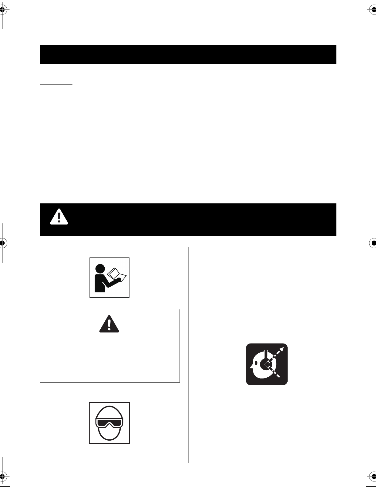
PRECAUTIONS ON USING THE TOOL
Danger to the eyes always exists due to the possibility of
dust being blown up by the exhausted air or of a fastener flying up due to the improper handling of the tool. For these
reasons, safety glasses or goggles shall always be worn
when operating the tool.
The employer and/or user must ensure that proper eye protection is worn. Eye protection equipment must conform to
the requirements of the American National Standards Institute, ANSI Z87.1 (Council Directive 89/686/EEC of 21 DEC.
1989) and provide both frontal and side protection.
The employer is responsible to enforce the use of eye protection equipment by the tool operator and all other personnel in the work area.
NOTE: Non-side shielded spectacles and face shields
alone do not provide adequate protection.
2. EAR PROTECTION MAY BE REQUIRED IN SOME ENVIRONMENTS
As the working condition may include exposure to high noise
levels which can lead to hearing damage, the employer and
user should ensure that any necessary hearing protection is
provided and used by the operator and others in the work area.
1. WEAR SAFETY GLASSES OR GOGGLES
3
Page 4
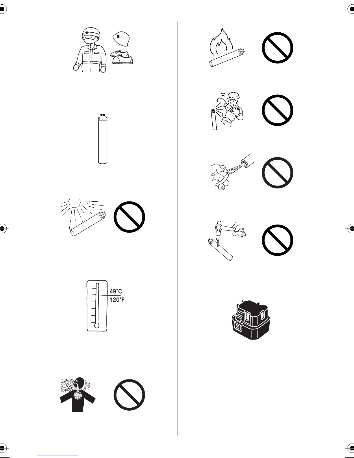
3. WEAR THE CLOTHINGS AND A PROTECTIVE GEAR
SUITABLE FOR THE WORKING ENVIRONMENT
Depending on the working environment, wear a long-sleeve
work uniform and a protective gear such as a hard hat, safety shoes.
4. CAUTIONS FOR FUEL CELL
1 Be sure to set Fuel Cell.
2 Store Fuel Cell in well ventilated area.
6 Do not incinerate or recycle the empty Fuel Cell.
7 Never jet the gas to the human body.
8 Do not remove the rubber plug from the bottom of the
Fuel Cell except at disposal.
3 Do not expose the Fuel Cell to the direct sunshine.
Do not place the Fuel Cell in a vehicle or a trunk where the
temperature could rise. It could explode. A used empty Fuel
Cell still contains a combustible jet gas, which could swell
and explode a container into pieces.
4 Store the Fuel Cell at ambient temperature of 120°F
(49°C) or lower.
The Fuel Cell contains the pressurized combustible gas. If
it is exposed to the temperature higher than 120°F (49°C),
the gas could leak from it or burst, resulting in a fire.
9 Do not make a hole in the Fuel Cell.
5. CAUTIONS FOR CHARGING METHOD, THE CHARGER
AND THE BATTERY
1 Be sure to use MAX JP606H battery for the tool.
Be sure to use MAX JP606H battery. Never connect the tool
to a power source or other rechargeable battery, dry cells or
storage battery for automobiles.
Neglect of this could cause breakage, trouble, heat generation or combustion.
(See Page 10 for MAX JP606H battery)
5 Do not breathe in the gas.
4
Page 5

2 Be sure to charge with MAX JC610M charger.
Be sure to charge the Battery with MAX JC610M charger.
If charged with other charger, it could fail to be properly
charged as well as get broken, ignited or generate the heat.
(See Page 10 for MAX JC610M charger)
3 Charge the Battery prior to use.
The new Battery or the one which has not been used for a
long period may not be fully charged due to self-discharge.
Be sure to charge it with MAX JC610M charger.
6 Never use an engine generator or DC power source to
charge the Battery.
Neglect of this causes a trouble or burnout of the charger.
7 Never charge the Battery in the rain or in the place ex-
posed to water splash or moisture.
If it is charged in the wet condition, it could cause an electric
shock or short-circuiting, resulting in a fire due to burnout or
combustion.
8 Never touch a power plug with a wet hand.
Holding it with a wet hand could cause an electric shock.
4 Charge the Battery at the specified voltage.
Be sure to charge, using a 100-240 V AC plug socket (for
household use). Never charge at other than the specified
voltage. Neglect of this could cause combustion or heat
generation.
5 Never use a transformer such as a booster for the pow-
er source of the charger.
Neglect of this causes a trouble or burnout of the charger.
9 Never cover the charger in use with a cloth, and so on.
Putting a cover could generate the heat, resulting in a burnout or fire.
0 Do not put the charger close to a fire.
5
Page 6
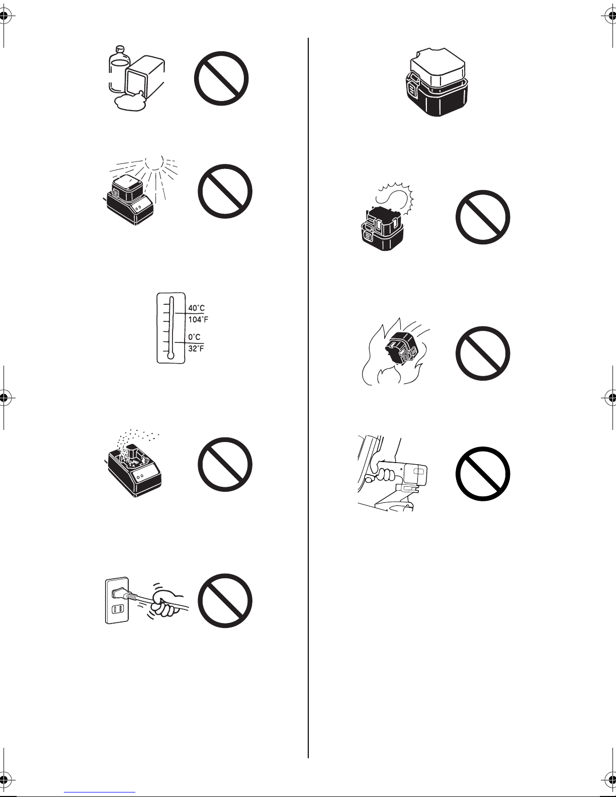
Thinner
Gasoline
a Do not charge the Battery near any combustible sub-
stance.
b Charge the Battery in a well-ventilated area, protected
against the direct sunshine.
Charging in the direct sunshine could overheat the charger,
resulting in a burnout or fire.
c Charge the Battery at ambient temperature of 32°F (0°C)
to 104°F (40°C).
If the ambient temperature is less than 32°F (0°C) to 104°F
(40°C), charging may not be allowed, could result in a fire.
f Once the Battery is disconnected from the tool body, be
sure to cover it with a pack cap, unless it is used.
In order to prevent short-circuiting, cover the terminal block
(metal section) of the unused Battery with the pack cap.
g Never short-circuit the terminal block (metal section) of
the Battery.
If it is short-circuited, a large current will run to overheat the
Battery, causing you a burn or damage on it.
h Never throw the Battery into a fire.
Neglect of this could cause an explosion.
d Do not allow foreign objects into a ventilation hole or
Battery plug socket in the charger.
They cause an electric shock or trouble. Use in the place
free of dust.
e Handle a power cord with care.
If you hold the power cord of the AC adapter to carry or pull
it to disconnect from a plug socket, it will be damaged, resulting in snapping or short-circuiting. Also, take care that it
will not come into contact with cutters, high-temperature
substances, oil or grease. Replace the damaged power
cord with a new one.
6. CARE SHOULD BE TAKEN WHEN CONNECTING THE
BATTERY TO THE TOOL
When connecting the Battery to the tool, be sure to observe
the following in order to prevent malfunctioning.
(1) Do not put your finger on the trigger.
(2) Do not press the contact arm against the object.
(3) Never put your finger or hand near the muzzle.
7. BE SURE TO CHECK WHEN THE BATTERY IS CONNECTED
Prior to using the tool, connect the Battery to it without
pressing the contact arm against the object and loading the
pins and Fuel Cell, and be sure to check the following:
6
Page 7
(1) Check whether or not operating sound is heard, by
only connecting the Battery.
* If you connect the Battery and press the contact arm
against the floor, and so on, the fan of the tool will
run, but this is not abnormal.
(2) Check for heat generation or abnormal smell or sound.
If the tool is activated, generates the heat or emits abnormal smell or sound, it is an indication of trouble.
Using the tool in that condition results in an accident.
If any abnormality is found, contact your nearest authorized distributor.
Thinner
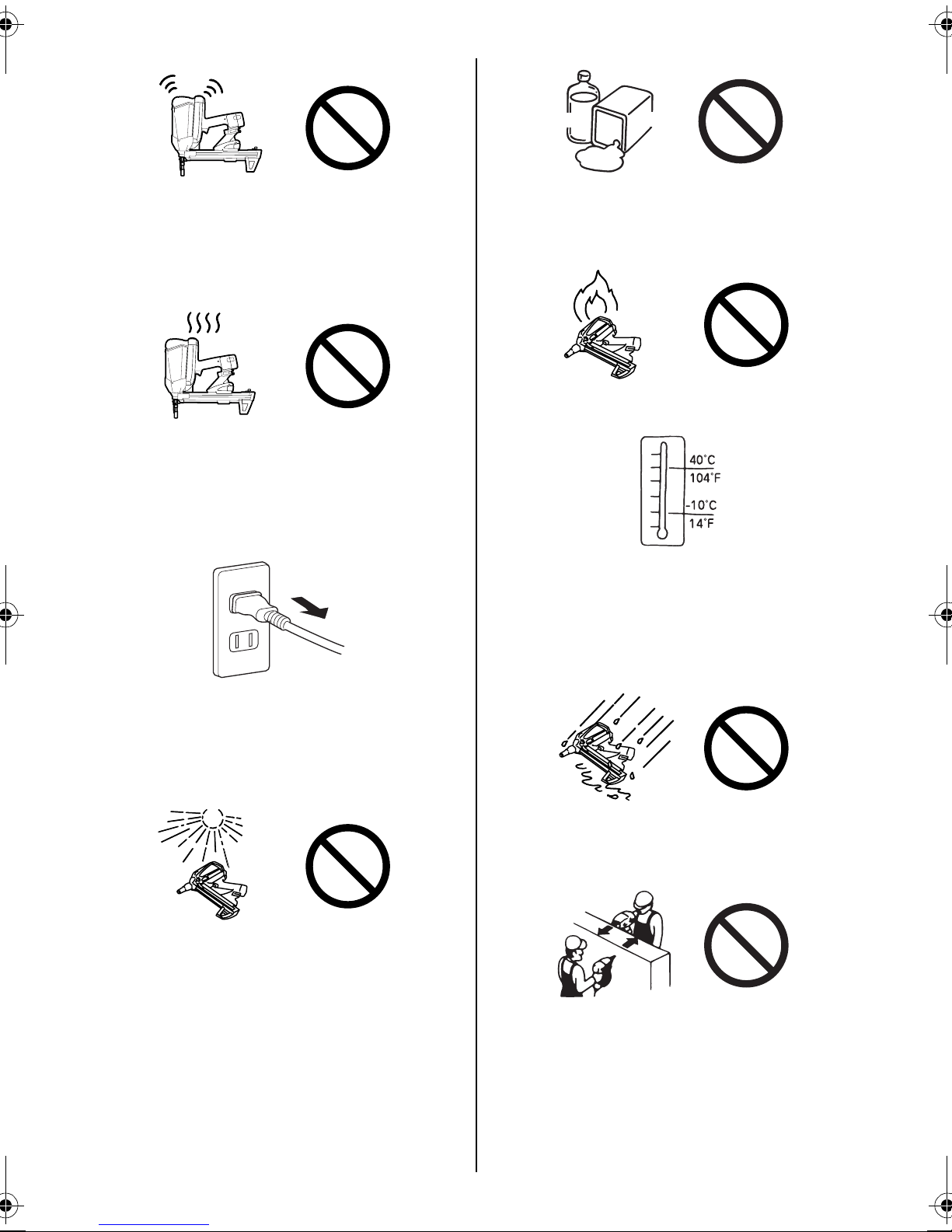
11. NEVER USE THE TOOL NEAR THE VOLATILE COMBUSTIBLE SUBSTANCES
Never use the tool near gasoline, thinner, gas, paint or adhesive agent, because it could ignite or explode.
12. KEEP TOOL AWAY FROM FIRE
13. BE SURE TO USE THE TOOL IN THE WORKING ENVIRONMENT OF 14°F (-10°C) TO 104°F (40°C), BECAUSE
THE TOOL BODY COULD BE DAMAGED, IGNITE OR
EXPLODE
14°F (-10°C) or lower: The tool body could be damaged.
104°F (40°C) or higher: The Fuel Cell could be damaged,
resulting in ignition or explosion.
Gasoline
8. UNPLUG THE CHARGER WHEN IT IS NOT USED
9. ONLY USE TOOL IN WELL VENTILATED AREA
If used in an ill-ventilated place, you could suffer from oxygen starvation.
10. AVOID THE DIRECT SUNSHINE
Do not place the tool in a vehicle or a trunk where the temperature could rise, because it could explode. A used empty
Fuel Cell still contains a combustible jet gas, which could
swell and explode a container into pieces.
14. DO NOT USE THE TOOL IN THE RAIN OR IN A VERY
HUMID PLACE
Neglect of this causes a trouble.
15. NEVER DRIVE THE PINS, FACING EACH OTHER
If you drive the pins, facing each other, an improperly driven
pin may hit and injure the worker facing you.
7
Page 8

16. BEWARE OF THE HIGH TEMPERATURE OF THE TOOL
If the tool is used for a long period of time, the nose and contact arm will become hot. Be careful not to get a burn.
17. WHEN USING THE HOOK, BE SURE TO RELEASE
YOUR FINGER FROM THE TRIGGER
20. DO NOT TOUCH THE TRIGGER UNLESS YOU INTEND
TO DRIVE A FASTENER
Never touch the trigger unless you intend to drive a fastener
into the work. It is dangerous to walk around carrying the
tool with the trigger pulled, and this and similar actions
should be avoided.
21. NEVER POINT THE DISCHARGE OUTLET TOWARD
YOURSELF AND OTHER PERSONNEL
If the discharge outlet is pointed toward people, serious accidents may be caused when misfiring. Be sure the discharge outlet is not pointed toward people when the Fuel
Cell and the Battery are inserted or not, loading and unloading the fasteners or similar operations.
18. REMOVE THE FUEL CELL AND THE BATTERY AND
EMPTY THE MAGAZINE WHEN THE TOOL IS NOT IN
USE
Always remove the Fuel Cell and the Battery from the tool
and empty the magazine when operation has been completed or suspended, when unattended, moving to a different work area, adjusting, disassembling, or repairing the
tool, and when clearing a jammed fastener.
19. INSPECT SCREW TIGHTNESS
Loose or improperly installed screws or bolts cause accidents and tool damage when the tool is put into operation.
Inspect to confirm that all screws and bolts are tight and
properly installed prior to operating the tool.
CAUTION
Be sure that the tool has been cool down.
22. USE SPECIFIED FASTENERS
The use of fasteners other than specified fasteners will
cause the tool malfunction. Be sure to use only specified
fasteners when operating the tool.
23. PLACE THE DISCHARGE OUTLET ON THE WORK SURFACE PROPERLY
Failure to place the discharge outlet of the nose in a improper manner can result in a fastener flying up and is extremely
dangerous.
24. KEEP HANDS AND BODY AWAY FROM THE DISCHARGE OUTLET
When loading and using the tool, never place a hand or any
part of body in fastener discharge area of the tool. It is very
dangerous to hit the hands or body by mistake.
8
Page 9

25. DO NOT DRIVE FASTENERS CLOSE TO THE EDGE
AND CORNER OF THE WORK AND THIN MATE RIAL
The workpiece is likely to split and the fastener could fly free
and hit someone.
26. DO NOT DRIVE FASTENERS ON TOP OF OTHER FASTENERS
Driving fasteners of the top of other fasteners may cause
deflection fasteners which could cause injury.
27. REMOVING THE FASTENERS AFTER COMPLETING
OPERATION
If fasteners are left in the magazine after the completion of
operation, there is the danger of a serious accident occurring prior to the resumption of operation, should the tool be
handled carelessly, or when inserting the Fuel Cell and the
Battery. For this reason, always remove all fasteners remaining in the magazine after completion of the operation.
28. CHECK OPERATION OF THE CONTACT TRIP MECHANISM FREQUENTLY IN CASE OF USING A CONTACT
TRIP TYPE TOOL
Do not use the tool if the trip is not working correctly as accidental driving of a fastener may result.
Do not interfere with the proper operation of the contact trip
mechanism.
32. ALWAYS ASSUME THAT THE TOOL CONTAINS FASTENERS
33. RESPECT THE TOOL AS A WORKING IMPLEMENT
34. NO HORSEPLAY
35. NEVER LOAD THE TOOL WITH FASTENERS WHEN
ANY ONE OF THE OPERATING CONTROLS (e.g., TRIGGER, CONTACT ARM) IS ACTIVATED
36. TAKE GOOD CARE OF THE TOOL
Clean the tool with dry soft cloth. Never use wet cloth or volatile solutions such as thinner, benzine.
37. AVOID THE DIRECT SUNSHINE
Do not leave the tool or Charger in the direct sunshine for a
long time.
OBSERVE THE FOLLOWING GENERAL CAUTION IN ADDITION TO THE OTHER WARNINGS
CONTAINED IN THIS MANUAL
• Do not use the tool as a hammer.
• The tool must be used only for the purpose it was
designed.
• Never remove, tamper with the operating controls
(e.g., TRIGGER, CONTACT ARM)
• Keep the tool, the Fuel Cell and the Battery in a
dry place out of reach of children when not in use.
• Do not use the tool without Safety Warning label.
• Do not modify the tool from original design or
function.
29. WHEN USING THE TOOL OUTSIDE OR ELEVATED
PLACE
When fastening roofs or similar slanted surface, start fastening at the lower part and gradually work your way up.
Fastening backward is dangerous as you may loose your
foot place.
30. NEVER USE THE TOOL IF ANY PORTION OF THE TOOL
CONTROLS (e.g., TRIGGER, CONTACT ARM) IS INOPERABLE, DISCONNECTED, ALTERED OR NOT WOKING PROPERLY
31. NEVER ACTUATE THE TOOL INTO FREE SPACE
This will avoid any hazard caused by free flying fasteners
and excessive strain of the tool.
9
Page 10

2. SPECIFICATIONS AND TECHNICAL DATA
1. NAME OF PARTS
1 Cylinder Cap Unit
2 Fuel Cap
3 Housing
4 LED
5 Trigger
6 Battery
7 Hook
8 Nail Stopper
9 Contact Arm
0 Follower
a Follower Holder
NOTE: The triangle symbol marked as "V" following its tool serial number indicates that safety yoke is equipped with this tool.
2. TOOL SPECIFICATIONS 3. FASTENER SPECIFICATIONS
b Magazine
c Magazine Foot
d Pack Cap
e Terminal Block
f MAX JP606H battery
g Battery Setting Hollow
h Jack
i Power Cord
j MAX JC610M charger
k Power Plug
l AC Adapter
PRODUCT NO. GS732C LT
HEIGHT 14-3/8" (365 mm)
WIDTH 4-7/8" (124 mm)
LENGTH 17-1/8" (435 mm)
WEIGHT 8.1 lbs. (3.7 kg)
LOADING CAPACITY
BATTERY
BATTERY CAPACITY
CHARGER
POWER SOURCE
POWER CONSUMPTION
(Rated output)
CHARGING TIME 150 minutes at maximum
ACCESSORIES Safety Glasses, Carrying case, Bat-
4. TECHNICAL DATA
1 NOISE
A-weighted single-event ------ LWA, 1s, d 103.38 dB
sound power level
A-weighted single-event ------ LpA, 1s, d 97.34 dB
emission sound pressure
level at work station
These values are determined and documented in accordance to EN12549 : 1999.
2 VIBRATION
Vibration characteristic value = 6.00 m/s
These values are determined and documented in accordance to ISO 8662-11.
This value is a tool-related characteristic value and does not represent the influence to the hand-arm-system when sing the tool.
An influence to the hand-arm-system when using the tool will for example depend on the gripping force, the contact pressure force, the
working direction, the workpiece, the workpiece support.
(including Fuel Cell and Battery)
42 pins
MAX JP606H battery
6V DC, 1.5 Ah
MAX JC610M charger
100-240V AC, 50 or 60 Hz
8VA (10V 800mA)
tery, Charger, Jam clear tool
2
PRODUCT NO. GS732C LT
PIN LENGTH 1/2" to 1-1/4" (12 to 32 mm)
SHANK DIAMETER .102", .120", .145"
(2.6 mm, 3.0 mm, 3.7 mm )
SHANK TYPE Smooth, Step
HEAD DIAMETER .252" (6.4 mm)
10
Page 11

3. SAFETY DEVICES
The tool is provided with the following safety devices in order to
secure safety for pin driving work.
Trigger
Contact Arm
Mechanical Safety Device
This tool is equipped with a FULL SEQUENTIAL ACTUATION
MECHANISM. This tool will not discharge pins unless the Contact Arm and Trigger have been activated simultaneously. The
pins are not discharged by neither simply pulling the Trigger nor
applying the Contact Arm to the pins driving object. The pins are
discharged only after apply the Contact Arm to the object and
pulling the Trigger.
4. HOW TO USE THE BATTERY
AND THE CHARGER
WARNING
• Be sure to charge MAX JP606H battery for the tool with
MAX JC610M charger.
If charged with other charger, the Battery could fail to be
properly charged as well as get broken, ignited or generate the heat.
• Do not put the Battery close to a fire.
• Do not leave the Battery in the direct sunshine.
• Do not charge or use the Battery in the wet condition with
a liquid such as water, sea water, milk, soft drink, soap
water.
• Unplug the charger when it is not used.
• Be sure to charge at 32°F (0°C) to 104°F (40°C) to avoid the
possibility of fire.
• Do not give a strong shock such as hitting with a hammer,
stamping or dropping.
CAUTION
• When the Battery is discharged or is not used for a long
period, remove it from the Charger.
• After setting the Battery in the tool, do not hold it to carry
around.
CAUTION
• Prior to using the tool, be sure to inspect it to see whether
the safety devices function properly. Do not use it if they
do not function properly.
Prior to using the tool, check whether the safety devices
function properly. With no pins loaded, install the Battery
and Fuel Cell to check.
∗ In the following cases, the safety devices are out of order.
Never use the tool.
1. An operating sound is emitted by simply pulling the trigger.
2. The tool starts dry-fire operation by simply applying the con-
tact arm to the object.
∗ A fan running sound is heard, this is OK.
If any abnormality is found, contact your nearest authorized distributor for inspection/repairing.
WARNING
• To avoid accidental firing or double firing, pull the trigger
rapidly and firmly.
PROPER USE OF BATTERY
1 Fully charge and discharge the Battery.
If you repeat charging the Battery while not fully discharged
more than half the capacity, the number of pins drivable by
each charging could decrease dramatically, shortening the
life of the Battery. It is recommended to use it until the LED
of the tool has been illuminated in red, running out of electricity.
2 Use two Batterys alternately.
To ensure the longer life of the Battery, it is recommended
to use two of them alternately, preparing a spare one.
Recycling the Nickel-Hydrogen Battery
The Battery for the tool uses nickel-hydrogen batteries which are
a precious recyclable resource. Once the Battery runs out of life,
take it to your nearest distributor without disposing of it.
WARNING
• In order to prevent short-circuiting, be sure to cover the
terminal block (metal section) of the Battery with the Pack
Cap (wind the insulating tape) for recycling.
<Battery cells in Battery Pack>
• Nominal voltage: 1.2 V/piece
• Quantity used in 1 pack: 5 pieces
11
Page 12

HOW TO USE THE CHARGER
The special purpose charger Base (Cat.#55638) has the LEDs (green, red) which indicate the status of the charger and Battery.
Green LED Red LED Status Description
1. ON OFF Power-on The charger has been plugged in. (Power-on status:Battery unset)
2. OFF ON Charging The Battery is being charged.
3. ON OFF Charge Completed The Battery has been completed charged.
4. Blinking Blinking High temperature
alarm
5. ON ON Battery alarm The Battery is defective. (Replace it with a new one)
6. Blinking ON Battery high
temparature alarm
Battery Charger problems
The following cases are considered to be the problems. Replace the charger and Battery with new ones.
• The green LED is not turned on if the power plug of the charger is plugged into a 100-240 V AC (for household use) plug socket. (With
the Battery unset)
∗ Check with another electric appliance to see whether electricity is available at the plug socket.
• Neither green nor red LED is turned on or blinks if the Battery is set in the Charger.
• The green LED is not turned on 150 minutes after the red one has been turned on.
• The red LED is not turned on if the Battery is set in the charger.
The Battery is hot. (Remove it from the Charger and cool it down for
a while before charging.)
The Battery is defective and hot. (Replace it with a new one.)
12
Page 13

HOW TO CHARGE
WARNING
• Charge the Battery at the specified voltage.
Be sure to charge from a 100-240 V AC (for household
use) plug socket. Use of the non-specified voltage not
only causes a trouble, but also is dangerous.
• Handle the power cord with care.
Do not use the Charger whose power cord is damaged.
• Use a proper plug socket.
Use of the rickety or slack plug socket causes an accident
due to overheat. If this is the case, use another proper
one.
Latch
Battery
Red LED
Charger
3 Charge the Battery.
(1) Set the Battery firmly in the charger.
(2) Once it is set in the charger, charging will start automatical-
ly. The red LED is turned on to inform you that charging is
under way.
(3) The maximum charging time is approx. 150 minutes. The
charging time depends on the temperature, supply voltage
or remaining battery capacity. Once charging is fully completed, the green LED will be illuminated to inform you that
charging has been completed. If the fully charged Battery is
set in the charger again, the red LED will be turned on
again, indicating that it is being charged. This is not an abnormality. After a while, the green LED will be turned on to
indicate completion of charging.
AC Adapter
1 If the Battery is used up, remove it from the tool.
Firmly holding the tool body, press the latches on both side
of the Battery with your fingers to remove.
Green LED
AC Adapter
Charger
2 Insert the AC adapter’s jack into the Charger and plug the
power plug into a plug socket.
The green LED is turned on to inform you of the power-on
status.
CAUTION
• Do not try to charge the Battery which has been fully
charged. The life of the Battery could be shortened.
4 The Illuminated Green LED Indicates completion of charg-
ing.
(1) Holding down the charger, remove the Battery.
(2) Disconnect the AC adapter’s power plug from the plug sock-
et.
Now Charging is complete.
Preventing the Battery Pack from becoming inactive
In the following cases the Battery Pack must be charged for 24
HOURS to reach top performance:
• Upon purchasing the tool.
• When the tool has not been used for 1 month or longer.
• When it is clear that you can drive less pins even when fully
charged.
After the Charge Complete lamp has been turned on, leave the
Battery set in the Charger for about another 24 hours.
13
Page 14

CAUTION
• After completing your work or when the tool is not used,
be sure to remove the Battery Pack from the tool to store
it. (Remove the Fuel Cell and pins as well)
If it is left connected, the electric power will be consumed
in the standby state.
Fuel
Cap
Fuel Cap
5. HANDLING OF FUEL CELL
The Fuel Cell is doubly structured; the inner container has been
filled with a liquid fuel gas and the outer one with a propellant gas
(another pressurized gas).
Like squeezing a toothpaste tube, the inner fuel gas is pushed
out by the pressure of the propellant gas, thus being used up to
the last without wasting it. Because of this structure, the combustible propellant gas in the outer container remains even after the
fuel gas in the inner container has been used.
Therefore, utmost care should be taken when disposing the empty Fuel Cell.
WARNING
• Be sure to use the Fuel Cell exclusively designed for the
Gas powered Fastening System.
• Never smoke a cigarette when attaching or operating a
metering valve.
• Do not remove the rubber plug from the bottom of the Fuel
Cell except at disposal.
• Do not make a hole in the Fuel Cell.
• Be careful not to breathe in the gas.
Breathing in the gas could cause sleepiness, dizziness or
nausea.
• Never jet the gas to the human body.
• Do not incinerate or recycle the empty Fuel Cell.
(See Page 15 for disposal of the Fuel Cell)
1 Press the Latch, then pull the Fuel Cap.
Fuel Cell
2 Insert the Fuel Cell into the tool.
INSERTING THE FUEL CELL INTO THE TOOL
WARNING
• Be sure to remove the Battery.
• Be sure to release your finger from the Trigger.
• Do not press the Contact Arm against the object.
3 You complete the loading of the Fuel Cell by closing the
Fuel Cap until it clicks.
∗ When the Fuel Cap is closed with the battery on the tool,the
Solenoid valve in the tool pushes out the air from the Solenoid
valve chamber and you hear a sound of air blow . This is the
normal sound for the tool activation.
4 It may be necessary to depress the Contact Arm 3 times
without pulling the trigger when changing a Fuel Cell.
14
Page 15

DISPOSING OF THE USED FUEL CELL
Combustible jet gas still remains in the used Fuel Cell.
LOADING THE PINS
WARNING
• Do not throw the used Fuel Cell into a fire.
• Never smoke a cigarette.
• Never breathe in the gas.
6. INSTRUCTIONS FOR OPERA-
TION
Read section titled "SAFETY INSTRUCTIONS".
1. BEFORE OPERATION
1 Wear Safety Glasses or Goggles.
2 Do not insert the Fuel Cell and Battery.
3 Inspect screw tightness.
4 Check operation of the Contact Arm & Trigger if moving
smoothly.
5 Insert the Fuel Cell and Battery.
6 Hold the tool with finger-off the Trigger, then push the Con-
tact Arm against the work-piece. (The tool must not operate.)
7 Hold the tool with Contact Arm free from work-piece and pull
the Trigger. (The tool must not operate.)
8 Remove the Fuel Cell and Battery.
WARNING
• When loading the pins, be sure to release the finger from
the Trigger.
• Do not press the Contact Arm against the object.
Pin
Nail Stopper
(Back side)
Procedure
1 Load the pins into the slit in the rear of the Magazine until
they reach in front of the Nail Stopper.
WARNING
2. OPERATION
Wear safety glasses or goggles
Danger to the eyes always exists due to the possibility of dust being blown up by the exhausted air or of a fastener flying up due
to the improper handling of the tool. For these reasons, safety
glasses or goggles shall always be worn when operating the tool.
The employer and/or user must ensure that proper eye protection
is worn. Eye protection equipment must conform to the requirements of the American National Standards Institute, ANSI Z87.1
(Council Directive 89/686/EEC of 21 DEC. 1989) and provide
both frontal and side protection.
The employer is responsible to enforce the use of eye protection
equipment by the tool operator and all other personnel in the work
area.
NOTE: Non-side shielded spectacles and face shields alone do
not provide adequate protection.
WARNING
Keep hands and body away from the discharge outlet
When driving the fasteners because of dangerous of hitting the
hands or body by mistake.
CAUTION
• Abrupt release of the Follower Holder causes jamming of
pins or dry-firing.
Follower
Holder
2 Pull the Follower Holder as far to the rear and of the maga-
zine and release it gently.
15
Page 16

HOW TO DRIVE THE PINS
Procedure
1 Install the Battery and Fuel Cell.
2 Press the nose of the Contact Arm against where you want
to drive the pins.
The fan motor is activated, the fuel gas is jetted, mixing the
fuel with the air.
2
1
DRIVING DEPTH ADJUSTMENT
WARNING
• ALWAYS remove Fuel Cell and Battery before making adjustment.
CAUTION
• The Depth Adjustment Dial may be hot.
1 Press Contact Arm against the object.
2 Pull the Trigger.
3 Firmly pressing the Contact Arm, pull the Trigger. The pins
are driven into the object by combustion of the fuel.
WARNING
• Never put your face above the tool. Reaction of the tool
may cause an unexpected injury.
• Never bring your hand or finger close to the discharge
outlet.
4 The pins are not shot even if the Contact Arm is applied to
the object with the Trigger pulled. Release the Trigger and
repeat Step 2.
CAUTION
• The fan keeps running even after driving the pins.
The running time varies with operation speed.
Deeper
The driving depth adjustment is made by adjusting the Depth Adjustment Dial.
1 With Fuel Cell and Battery install, drive a few nails into a
representative material sample to determine if adjustment is
necessary.
2 If adjustment is required, remove Fuel Cell and Battery.
3 Refer to the mark on the Body Cover for direction to turn the
Adjustment Dial.
4 Reinstall Fuel Cell and Battery.
Shallower
Adjustment Dial
WARNING
• Prior to starting work, be sure to check whether the tool
functions as mentioned above.
• If the tool is used for a long period of time, it could get hot
and burn you.
If any abnormality is found, contact your nearest authorized distributor for inspection and repairing.
16
Page 17

REMOVING THE PIN
CHANGING THE HOOK DIRECTION
Follower
Pin
Follower
Holder
1 Pull the Follower Holder and press the Follower,then return
the Follow Folder.
Nail Stopper
Hexagon Socket
Head Cap Screw
Hook
WARNING
• Remove the Fuel Cell and Battery.
The Hook can be directed in the two directions. Remove the hexagon socket head cap screw with hexagon wrench, change the
direction, and then, put back the bolts to reassemble.
REPLACING THE FUEL CELL
If the Fuel Gas is low, the pins cannot be driven.
Pin
2 Set the Magazine vertical and push the Nail Stopper to re-
move the Pin. Be sure that no pins remain in the Nose or
Magazine.
WARNING
• Be sure to remove the Battery.
• Be sure to release the Trigger.
• Do not press the Contact Arm against the object.
Fuel Cap
Fuel
Cap
1 Press the Latch, then pull the Fuel Cap.
17
Page 18

Fuel Cell
2 Grab and remove the used Fuel Cell.
3 Set the new Fuel Cell.
(See Page 14 for the setting method)
4 It may be necessary to depress the Contact Arm 3 times
without pulling the trigger when changing a Fuel Cell.
REPLACING THE BATTERY
If the Battery is low, the red LED of the tool will be turned on.
WARNING
• Be sure to remove the Fuel Cell.
• Release the Trigger.
• Do not press the Contact Arm against the object.
Latch
Battery
1 Firmly holding the grip, press the latches on both sides of
the Battery to remove it.
18
Page 19

2 Install the newly charged Battery into the Housing until it
has clicked.
(See Page 13 for the charging method)
3 Install the Fuel Cell.
(See Page 14 for the Installation method)
7. MAINTAIN FOR PERFORMANCE
4. INSPECT THE TOOL PERIODICALLY
In order to maintain the performance of the tool, clean and
inspect the tool periodically. To have it inspected, contact
your nearest distributor.
5. CLEAN THE AIR FILTER
Clean the Air Filter every other day. Open the cylinder cap
unit with a regular screwdriver,and clean it with Compressed air.
CAUTION
• Be sure that the tool has been cool down.
1. HANDLE THE TOOL WITH CARE
Never drop, collide or hit the tool against a hard material. It
may be deformed, cracked or damaged.
2. DO NOT TRIGGER THE TOOL WITH NO PINS LOADED
If you repeatedly operate the tool with no pins loaded, the
durability of each section will be reduced.
3. DO NOT LUBRICATE THE TOOL
Never lubricate the Tool because it will cause problems.
LED
6. MAINTENANCE LED INDICATOR
When the indicator light starts blinking, it is time to clean the
tool. Bring the tool to the MAX CO., LTD. authorized service
center for cleaning inside of the tool.
19
Page 20

7. PRODUCTION YEAR INDICATION
This product indicates production number at the lower part
of the grip. The first 2 digits of the number from left indicates
the product year.
(Example)
0 9 8 2 2 6 0 3 5 D
Year 2009
8. STORING
1 When not in use for an extended period, apply a thin coat of
the lubricant to the steel parts to avoid rust.
2 Do not store the tool in a cold weather environment. Keep
the tool in a warm area.
3 When not in use, the tool should be stored in a warm and
dry place. Keep out of reach of children.
4 All quality tools will eventually require servicing or replace-
ment of parts because of wear from normal use.
SLEEP-MODE
To save battery life this tool is equipped with Sleep-Mode function.
If the battery is left in the tool for more than 24 hours, the tool will
go into"Sleep-Mode" (the tool will not function.)
To restart the tool remove then reinstall the battery. This will allow
the tool to function normally.
9. TROUBLE SHOOTING/REPAIRS
1 The repairs shall be carried out only by the MAX CO., LTD.
authorized service center.
2 The tool is provided with a pin remover to ensure that the
jamming pins can be easily removed.
WARNING
• Remove the Fuel Cell, followed by the Battery.
Procedure
1 Remove the Fuel Cell, followed by the Battery.
2 Remove the pins remaining in the magazine.
Remove Lever
3 Pull up the Remove Lever and remove the Magazine from
the tool.
20
Page 21

Magazine Guide (Nose)
4 At this point, the jammed pin should fall out. If the jammed
pin does not fall out, carefully remove the pin taking care not
to damage the Nosepiece.
After you have removed the jammed pin, take the following
steps to assemble the Magazine into the tool.
5 Insert the front of the Magazine into the Magazine Guide
(Nose).
6 Make sure to align the Magazine with the Magazine Holder
with no gap.
Push the Remove Lever until it clicks.
21
Page 22

22
 Loading...