

Max GS690RH, GS690CH Maintenance Manual

• The content of this manual might be changed without notice for improvement.
• Änderungen der Betriebsanleitung zum Zwecke der Verbesserung ohne Ankündigung
vorbehalten.
• Le contenu de ce manuel est sujet à modification sans préavis à des fins
d’amélioration.
•I contenuti di questo manuale possono essere cambiati senza preavviso per motivi di
miglioramento del prodotto.
• El contenido de este manual puede ser cambiado sin noticia previa para mejoramiento.
PRINTED IN JAPAN GEDRUCKT IN JAPAN IMPRIMÉ AU JAPON STAMPATO IN GIAPPONE IMPRESO EN JAPÓN
Recycled paper is used for this manual and its recyclable.
GS690RH
GS690CH
MAX CORDLESS FASTENING SYSTEM
MAX SCHNURLOSES
BEFESTIGUNGSSYSTEM
SYSTÈME DE FIXATION SANS
CORDON MAX
SISTEMA DI FISSAZIONE SENZA
CORDONE MAX
SISTEMA DE FIJACIÓN SIN CORDÓN
MAX
OPERATING and MAINTENANCE MANUAL
BETRIEBSANLEITUNG
MANUEL D’UTILISATION et D’ENTRETIEN
MANUALE DI FUNZIONAMENTO E MANUTENZIONE
MANUAL DE OPERACIONES Y MANTENIMIENTO
BEFORE USING THIS TOOL, STUDY THIS MANUAL TO ENSURE SAFETY WARNING AND
INSTRUCTIONS.
KEEP THESE INSTRUCTIONS WITH THE TOOL FOR FUTURE REFERENCE.
LESEN SIE VOR INBETRIEBNAHME DES GERÄTES DIE GEBRAUCHS- UND SICHERHEITSHINWEISE. BITTE BEWAHREN SIE DIE GEBRAUCHS- UND SICHERHEITSHINWEISE AUF,
DAMIT SIE AUCH SPÄTER EINGESEHEN WERDEN KÖNNEN.
AVANT D’UTILISER CET OUTIL, LIRE CE MANUEL ET LES CONSIGNES DE SECURITE
AFIN DE GARANTIR UN FONCTIONNEMENT SUR.
CONSERVER CE MANUEL EN LIEU SUR AVEC L’OUTIL AFIN DE POUVOIR LE CONSULTER
ULTERIEUREMENT.
PRIMA DI USARE QUESTA MACCHINA, STUDIARE IL MANUALE PER PRENDERE ATTO
DEGLI AVVERTIMENTI E DELLE ISTRUZIONIPER LA SICUREZZA.
TENERE QUESTE ISTRUZIONI INSIEME ALLO STRUMENTO PER CONSULTAZIONI FUTURE
PARA EVITAR GRAVES DAÑOS PERSONALES O EN LA PROPIEDAD.
ANTES DE EMPLEAR LA HERRAMIENTA, LEER CON ATENCIÓN Y COMPRENDER LOS
SIGUIENTES INSTRUCCIONES DE SEGURIDAD.
WARNING:
ACHTUNG!
AVERTISSEMENT:
ATTENZIONE:
ATENCIÓN:
4008132
090202-00/01
•
The specifications and design of the products in this manual will be subject to change without
advance notice due to our continuous efforts to improve the quality of our products.
•
Änderungen bei technischen Daten und Design der Produkte in diesem Handbuch im Sinne der
Produktverbesserung bleiben vorbehalten.
•
Les caractéristiques et la conception des produits mentionnés dans ce manuel sont sujettes à des
modifications sans préavis en raison de nos efforts continus pour améliorer la qualité de nos
produits.
•
Le caratteristiche e la concezione dei prodotti menzionati in questo manuale sono soggette a
modifiche senza preavviso a causa dei nostri sforzi continui per migliorare la qualità dei nostri
prodotti.
•
Las características y la concepción de los productos mencionados en este manual están sujetas a
modificaciones sin preaviso debido a nuestros esfuerzos continuos para mejorar la calidad de
nuestros productos.
www.max-ltd.co.jp/int/ (GLOBAL Site)
www.max-europe.com (EUROPE Site)
OSTSTRASSE 22, 40211
DÜSSELDORF, GERMANY
TEL: +49-211-9365300
FAX: +49-211-93653017
Camerastraat 19
1322 BB Almere The Netherlands
Phone: +31-36-546-9699
FAX: +31-36-536-3985
E

2
INDEX INHALTSVERZEICHNIS INDEX INDICE INDICE
ENGLISH Page 3 to 24 Page
DEUTSCH Page 25 to 46 Page
FRANÇAIS Page 47 to 68 Page
ITALIANO Page 69 to 90 Page
ESPAÑOL Page 91 to 112 Page
DEFINITIONS OF SIGNAL WORDS
WARNING: Indicates a potentially hazardous situation which, if not avoided, could result in death or serious injury.
CAUTION: Indicates a potentially hazardous situation which, if not avoided, may result in minor or moderate injury.
NOTE: Emphasizes essential information.
DEFINITIONEN DER HINWEISBEZEICHNUNGEN
ACHTUNG! Zeigt eine eventuell gefährliche Situation an, die den Tod oder schwere Verletzungen zur Folge haben
könnte, wenn sie nicht vermieden wird.
VORSICHT! Zeigt eine eventuell gefährliche Situation an, die leichte oder mittelschwere Verletzungen zur Folge
haben könnte, wenn sie nicht vermieden wird.
HINWEIS: Hebt wichtige Informationen hervor.
DÉFINITIONS DES DIFFÉRENTS DEGRÉS D’ AVERTISSEMENTS
AVERTISSEMENT Indique une situation éventuellement dangereuse qui, si elle n’est pas contournée, pourrait provoquer la
mort ou des blessure sérieuses.
ATTENTION Indique une situation éventuellement dangereuse qui, si elle n’est pas contournée, pourrait provoquer
des blessures légères à moyennement sérieuses.
REMARQUE Souligne des informations importantes.
DEFINIZIONE DELLE INDICAZIONI DI AVVERTIMENTO
ATTENZIONE: Indica l’eventualità che possa verificarsi una situazione pericolosa, la quale se non viene evitata, può
risultare letale o provocare gravi lesioni.
AVVERTENZA: Indica l’eventualità che possa verificarsi una situazione pericolosa, la quale se non viene evitata, può
provocare lesioni di lieve o media entità.
NOTA: Evidenzia informazioni importanti.
DEFINICIÓN DE LAS INDICACIONES DE ADVERTENCIA
¡
ATENCIÓN! Indica una situación potencialmente peligrosa que podría causar la muerte o graves lesiones si no se
evita.
¡
PRECAUCIÓN! Indica una situación potencialmente peligrosa que podría causar lesiones menos graves o leves si no
se evita.
NOTA: Resalta informaciones importantes.
3
ENGLISH
GS690RH/GS690CH
MAX CORDLESS FASTENING SYSTEM
INDEX
1. SAFETY INSTRUCTIONS
……………
4
2. SPECIFICATIONS &
TECHNICAL DATA
…………………
11
3. SAFETY DEVICE
……………………
12
4. HOW TO USE THE BATTERY AND
THE CHARGER
……………………
13
5. HANDLING OF FUEL CELL
………
17
6.
INSTRUCTIONS FOR OPERATION…19
7. MAINTAIN FOR PERFORMANCE
…
23
8. STORING
……………………………
23
9. TROUBLESHOOTING/REPAIRS
……
24
OPERATING and MAINTENANCE MANUAL
BEFORE USING THIS TOOL, STUDY THIS MANUAL TO ENSURE SAFETY WARNING
AND INSTRUCTIONS.
KEEP THESE INSTRUCTIONS WITH THE TOOL FOR FUTURE REFERENCE.
WARNING:
114
4
1. SAFETY INSTRUCTIONS
PRECAUTIONS ON USING THE TOOL
1. WEAR SAFETY GLASSES OR GOGGLES
Danger to the eyes always exists due to the possibility of dust being blown up by the exhausted air
or of a fastener flying up due to the improper handling of the tool. For these reasons, safety glasses
or goggles always be worn when operating the tool.
The employer and/or user must ensure that proper eye protection is worn. Eye protection equipment
must conform to the requirements of the American National Standards Institute, ANSI Z87.1 (Council
Directive 89/686/EEC of 21 DEC. 1989) and provide both frontal and side protection.
The employer is responsible to enforce the use of eye protection equipment by the tool operator
and all other personnel in the work area.
NOTE: Non-side shielded spectacles and face shields alone do not provide adequate protection.
2. EAR PROTECTION MAY BE REQUIRED IN SOME ENVIRONMENTS
As the working condition may include exposure to high noise levels which can lead to hearing
damage, the employer and user should ensure that any necessary hearing protection is provided
and used by the operator and others in the work area.
3. WEAR THE CLOTHINGS AND A PROTECTIVE GEAR SUITABLE FOR THE WORKING
ENVIRONMENT
Depending on the working environment, wear a long-sleeve work uniform and a protective gear
such as a helmet, safety shoes.
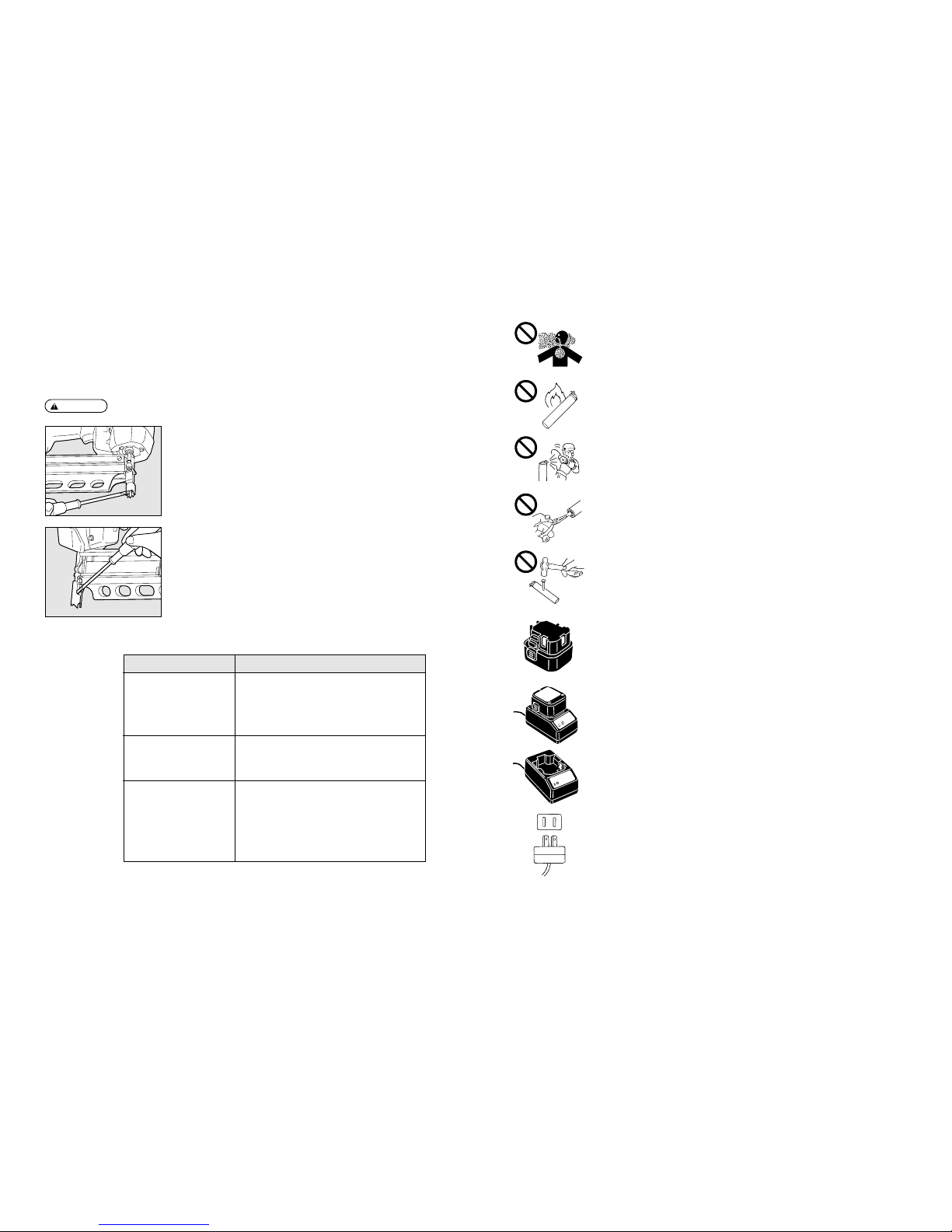
4. CAUTIONS FOR FUEL CELL
Contains flammable gases wlich are under pressure. Failure to follow instructions may result in
explosion or fire.
q
Be sure to use only MAX Fuel Cells.
w
Do not store the Fuel Cell in an ill-ventilated place.
e
Do not expose the Fuel Cell to the direct sunshine.
Do not place the Fuel Cell in a vehicle or a trunk where the temperature could rise. It could
explode. A used empty Fuel Cell still contains a combustible propellant gas, which could swell
and explode a container into pieces.
r
Store the Fuel Cell at ambient temperature of 49°C (120°F) or lower.
The Fuel Cell contains the pressurized combustible gas. If it is exposed to the temperature
higher than 49°C (120°F), the gas could leak from it or burst, resulting in a fire.
WARNING:
TO AVOID SEVERE PERSONAL INJURY OR PROPERTY DAMAGE
BEFORE USING THE TOOL, READ CAREFULLY AND UNDERSTAND THE FOLLOWING
“SAFETY INSTRUCTIONS”. FAILURE TO FOLLOW WARNINGS COULD RESULT IN DEATH OR
SERIOUS INJURY.
49°C
120°F
113
5
t
Do not breathe in the gas.
y
Do not incinerate or recycle the empty Fuel Cell.
u
Never jet the gas to the human body.
i
Do not remove a rubber plug from the bottom of the Fuel Cell except at disposal.
o
Do not make a hole in the Fuel Cell.
5. CAUTIONS FOR CHARGING METHOD, THE CHARGER AND THE BATTERY
q
Be sure to use MAX JP606H.
Be sure to use MAX JP606H for the tool. Never connect the tool to a power source or other
rechargeable battery, dry cells or storage battery for automobiles.
Failure to do this could cause breakage, trouble, heat generation or combustion.
(See Page 11 for MAX JP606H)
w
Be sure to charge with MAX JC610M.
Be sure to charge the Battery with MAX JC610M.
If charged with other charger, it could fail to be properly charged as well as get broken, ignited or
generate the heat. (See Page 11 for MAX JC610M)
e
Charge the Battery prior to use.
The new Battery or the one which has not been used for a long period may not be fully charged
due to self-discharge. Be sure to charge it with MAX JC610M.
r
Charge the Battery at the specified voltage.
Be sure to charge, using a 100-240 V AC plug socket (for household use). Never charge at other
than the specified voltage. Neglect of this could cause combustion or heat generation.
112
9. BÚSQUEDA DE AVERÍAS/REPARACIONES
q
Las reparaciones serán efectuadas solamente por los distribuidores MAX autorizados o por otros
especialistas.
w
Remoción de los clavos atascados
ADVERTENCIA:
●
Retirar la célula de combustible, luego la batería.
Fenómeno Item de control
e
La batería no puede cargarse.
・
La clavija de alimentación del adaptador de c.d. se conecta
firmemente a la toma de alimentación.
・
La toma jack del adaptador de c.d. se inserta firmemente
en el cargabatería.
・
La batería se coloca correctamente en el cargabatería.
・
Se ilumina la DEL del cargabatería.
Durante la carga, el cargabatería,
el adaptador de c.d. y el cable de
alimentación se calientan, emiten
un ruido anormal o producen calor.
・
Dejar de utilizarlos inmediatamente y consultar al
distribuidor más cercano.
Los clavos no pueden insertarse.
・
El cuerpo de la herramienta está cargado correctamente
con clavos, la batería y el combustible.
・
La duración de servicio de la célula de combustible no se
ha expirado.
・
La capacidad de batería es todavía residual.
・
Ningún atasco de clavos.
・
El brazo de contacto se aprieta correctamente contra el
objeto.
Método
q
Después de retirar los clavos, cerrar la puerta y asegurarse de que el pasador de
cerrojo se ha ajustado firmemente en el apoyo del pasador.
6
t
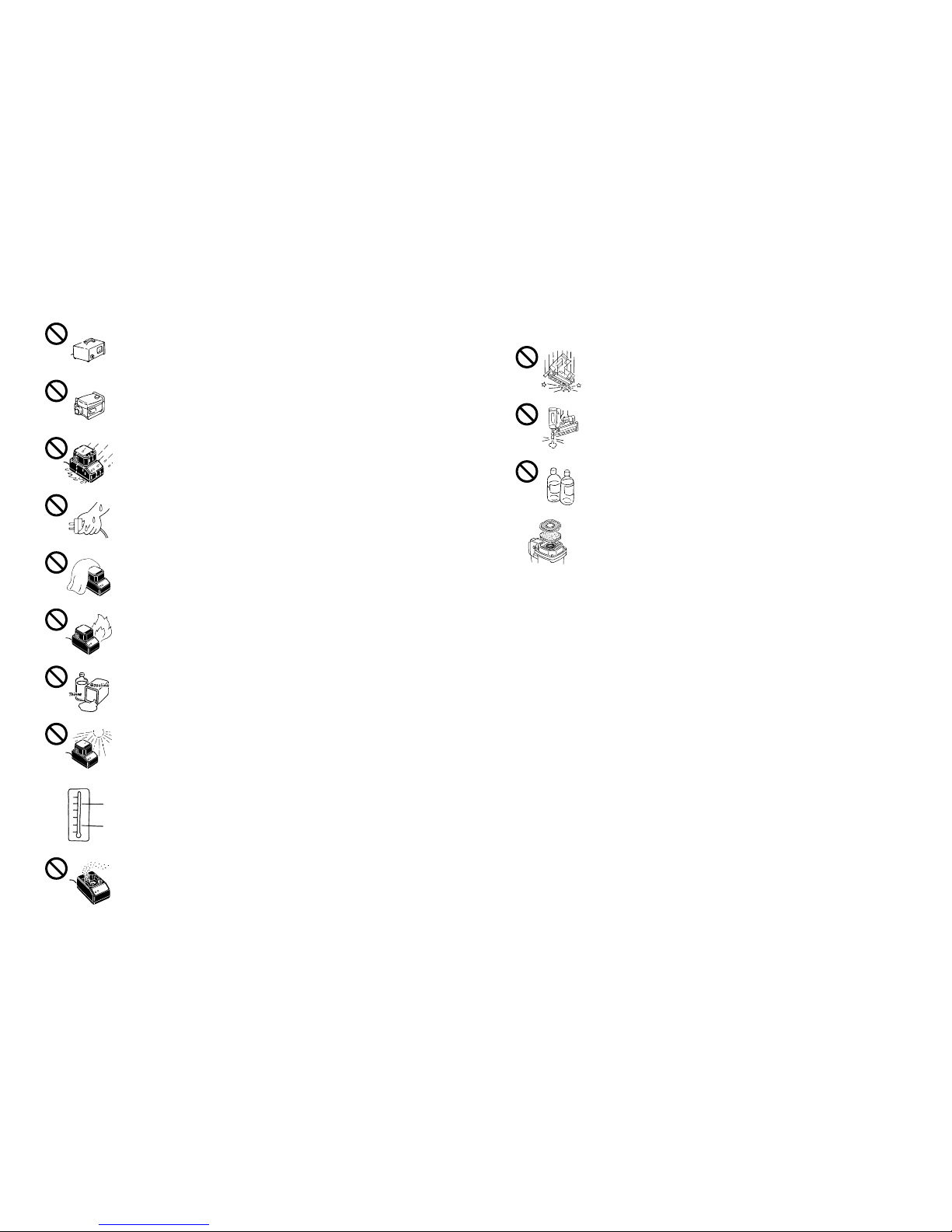
Never use a transformer such as a booster for the power source of the charger.
Failure to do will cause a problem or burnout of the charger this causes a trouble or burnout of
the charger.
y
Never use an engine generator or DC power source to charge the Battery.
Failure to do will cause a problem or burnout of the charger this causes a trouble or burnout of
the charger.
u
Never charge the Battery in the rain or in the place exposed to water splash or moisture.
If it is charged in the wet condition, it could cause an electric shock or short-circuiting, resulting
in a fire due to burnout or combustion.
i
Never touch a power plug with a wet hand.
Holding it with a wet hand could cause an electric shock.
o
Never cover the charger in use with a cloth, and so on.
Putting a cover could generate the heat, resulting in a burnout or fire.
!0
Do not bring the charger closer to a fire.
!1
Do not charge the Battery near any combustible substance.
!2
Charge the Battery in a well-ventilated place, protected against the direct sunshine.
Charging in the direct sunshine could overheat the charger, resulting in a burnout or fire.
!3
Charge the Battery at ambient temperature of 0°C (32°F) to 40°C (104°F).
If the ambient temperature is less than 0°C (32°F) to 40°C (104°F), charging may not be
allowed, could result in a fire.
!4
Do not allow foreign objects into a ventilation hole or Battery plug socket in the charger.
They cause an electric shock or trouble. Use in the place free of dust.
40°C
104°F
0°C
32°F
111
7. MANTENIMIENTO DEL RENDIMIENTO
1. MANEJAR LA HERRAMIENTA CON CUIDADO
Nunca dejar caer la herramienta, golpearla o tocarla contra una superficie dura. Puede deformarse
o dañarse.
2. NO UTILIZAR LA HERRAMIENTA SIN CARGAR LOS CLAVOS
Si se actua en varias veces la herramienta sin cargar los clavos, se reducirá la duración de servicio
de cada sección de la herramienta.
3. COMPROBAR LA HERRAMIENTA PERIÓDICAMENTE
Para obtener un buen rendimiento de esta herramienta, limpiar y examinar la herramienta
periódicamente. Para su inspección, les rogamos que consulte a los proveedores autorizados por
MAX.
4. LIMPIAR EL FILTRO DE AIRE
Limpiar el filtro de aire cada dos días. Abrir el casquillo del filtro de aire con un destornillador
normal, retirar el filtro de aire del interior y limpiarlo con un trapo de aire, etc.
8. ALMACENAJE
q
Cuando la herramienta no está en funcionamiento por un período prolongado, aplicar una capa fina
de lubricante a las partes de acero para evitar herrumbre.
w
No almacenar la herramienta en un sitio frío. Colocar la herramienta en un sitio caliente.
e
Cuando no se utiliza, la herramienta debería estar almacenada en un lugar caliente y seco. Alejar la
herramienta de la presencia de los niños.
r
Las herramientas de calidad exigirán un mantenimiento o una sustitución de las partes debido al
desgaste causado por uso normal.
7
!56
Handle a power cord with care.
If you hold the power cord of the AC adapter to carry or pull it to disconnect from a plug socket, it
will be damaged, resulting in snapping or short-circuiting. Also, take care that it will not come into
contact with cutters, high-temperature substances, oil or grease. Replace the damaged power
cord with a new one.
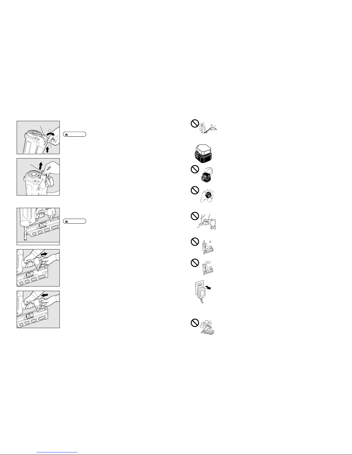
!6
Once the Battery is disconnected from the tool body, be sure to cover it with a pack cap,
unless it is used.
In order to prevent short-circuiting, cover the terminal block (metal section) of the unused Battery
with the pack cap.
!7
Never short-circuit the terminal block (metal section) of the Battery.
If it is short-circuited, a large current will run to overheat the Battery, causing you a burn or
damage on it.
!8
Never throw the Battery into a fire.
This could cause the Battery to expolde.
6. CARE SHOULD BE TAKEN WHEN CONNECTING THE BATTERY TO THE TOOL
When connecting the Battery to the tool, be sure to observe the following in order to prevent
malfunctioning.
1. Do not put your finger on the trigger.
2. Do not press the contact arm against the object.
3. Never put your finger or hand near the muzzle.
7. BE SURE TO CHECK WHEN THE BATTERY IS CONNECTED
Prior to using the tool, connect the Battery to it without pressing the contact arm against the object
and loading the nails and Fuel Cell, and be sure to check the following:
1. Check whether or not operating sound is heard, by only connecting the Battery.
※ If you connect the Battery and press the contact arm against the floor, and so on, the fan of the
tool will run, but this is not abnormal.
2. Check for heat generation or abnormal smell or sound.
If the tool is activated, generates the heat or emits abnormal smell or sound, it is an indication of
trouble. Using the tool in that condition results in an accident. If any abnormality is found, contact
your nearest MAX authorized distributor.
8. UNPLUG THE CHARGER WHEN IT IS NOT USED
9. DO NOT USE THE TOOL IN AN ILL-VENTILATED PLACE
If used in an ill-ventilated place, you could suffer from oxygen starvation.
10. AVOID THE DIRECT SUNSHINE
Do not place the tool in a vehicle or a trunk where the temperature could rise, because it could
explode. A used empty Fuel Cell still contains a combustible jet gas, which could swell and explode
a container into pieces.
110
SUSTITUCIÓN DE LA CÉLULA DE COMBUSTIBLE
Si se agota el gas combustible, los clavos no pueden insertarse.
●
Asegurarse de liberar correctamente el gatillo.
●
No apretar el brazo de contacto contra el objeto.
q
Levantar y tirar el casquillo de la célula de combustible hacia este lado para abrirla.
ADVERTENCIA:
SUSTITUCIÓN DE LA BATERÍA
Si la batería está agotada, se iluminará la DEL roja de la herramienta.
●
Asegurarse de retirar la célula de combustible.
●
Liberar el gatillo.
●
No apretar el brazo de contacto contra el objeto.
ADVERTENCIA:
w
Agarrar la válvula de chorro y retirar la célula de combustible agotada.
e
Ajustar la nueva célula de combustible.
(Véase la página 106 para el método de ajuste).
q
Manteniendo firmemente el cuerpo principal, apretar los pestillos de ambos lados de
la batería para retirarlo.
2
1
Casquillo de la célula de combustible
Injector de chorro
Célula de combustible
Batería
Pestillo
w
Ajustar la batería que se ha cargado en el cuerpo principal hasta que cliquea.
(Véase la página 103 para el método de cargado).
e
Ajustar la célula de combustible.
(Véase la página 106 para el método de ajuste).
8
11. NEVER USE THE TOOL NEAR THE VOLATILE COMBUSTIBLE SUBSTANCES
Never use the tool near gasoline, thinner, gas, paint or adhesive agent, because it could ignite or
explode.
12. NEVER USE THE TOOL IN AN EXPLOSIVE ATMOSPHERE
Sparks from the tool may ignite atmospheric gases, dust or other combustible materials.
13. DO NOT BRING THE TOOL CLOSE TO FIRE
14. BE SURE TO USE THE TOOL IN THE WORKING ENVIRONMENT OF -5°C (23°F) TO 49°C
(120°F), BECAUSE THE TOOL BODY COULD BE DAMAGED, IGNITE OR EXPLODE
-5°C (23°F) or lower: The tool body could be damaged.
49°C (120°F) or higher: The Fuel Cell could be damaged, resulting in ignition or explosion.
15. DO NOT USE THE TOOL IN THE RAIN OR IN A VERY HUMID PLACE
Neglect of this causes a trouble.
16. NEVER DRIVE THE NAILS, FACING EACH OTHER
If you drive the nails, facing each other, an improperly driven nail may hit and injure the worker
facing you.
17. BEWARE OF THE HIGH TEMPERATURE OF THE TOOL
If the tool is used for a long period of time, the nose and contact arm will become hot. Be careful not
to get a burn.
18. WHEN USING THE HOOK, BE SURE TO RELEASE YOUR FINGER FROM THE TRIGGER
When using the hook, be sure to release your finger from the trigger.
19. REMOVE THE FUEL CELL AND THE BATTERY AND EMPTY THE MAGAZINE WHEN THE
TOOL IS NOT IN USE
Always remove the Fuel Cell and the Battery from the tool and empty the magazine when operation
has been completed or suspended, when unattended, moving to a different work area, adjusting,
disassembling, or repairing the tool, and when clearing a jammed fastener.
20. INSPECT SCREW TIGHTNESS
Loose or improperly installed screws or bolts cause accidents and tool damage when the tool is put
into operation. Inspect to confirm that all screws and bolts are tight and properly installed prior to
operating the tool.
49°C
120°F
−5°C
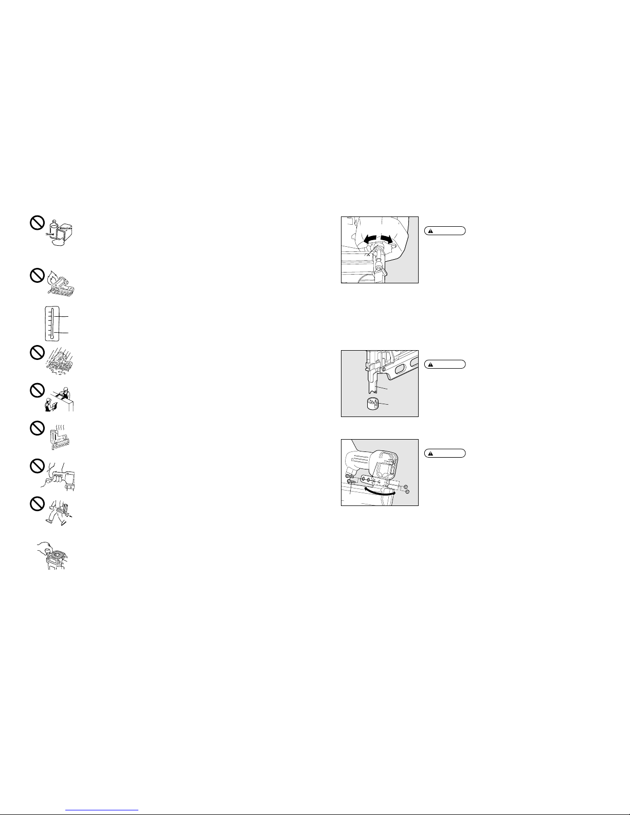
23°F
AJUSTE DE LA PROFUNDIDAD DE HUNDIMIENTO
●
SIEMPRE retirar la célula de combustible y la batería antes de efectuar el
ajuste.
●
Comprobar si se calentó el cuadrante de ajuste.
●
El cuadrante de ajuste puede recalentarse cuando la herramienta se ha
utilizada constantemente.
El ajuste de la profundidad de hundimiento se efectúa regulando el cuadrante de ajuste.
q
Con la célula de combustible y la batería ajustadas, insertar algunos clavos en una
muestra material modelo para determinar si el ajuste es necesario.
w
Si el ajuste es necesario, retirar la célula de combustible y la batería.
e
Referirse a la marca sobre el cargador de puntas para la dirección de rotación del
cuadrante de ajuste.
r
Instalar de nuevo la célula de combustible y la batería.
109
ADVERTENCIA:
Bloque de clavos
Mayor
profundidad
Menor
profundidad
EXTREMIDAD DE CONTACTO (OPCIÓN)
●
SIEMPRE desconectar la botella de gas y la bateria antes de sujetar / remover
la caperuza de contacto.
Sujetar la caperuza de contacto al brazo de contacto, cuando se insertan los clavos en
un material suave.
Brazo de contacto
Caperuza de
contacto
●
Retirar la célula de combustible y la batería.
ADVERTENCIA:
CAMBIO DE LA DIRECCIÓN DEL GANCHO
El gancho puede orientarse en ambas direcciones. Retirar los tornillos con cabeza
hueca hexagonal con la clave accesoria 4 a seis lados, cambiar la dirección, luego
volver a poner los pernos en posición para remontar.
Tornillos con cabeza
hueco hexagonal
Gancho
ADVERTENCIA:
9
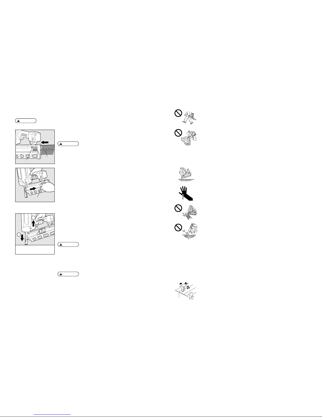
21. DO NOT TOUCH THE TRIGGER UNLESS YOU INTEND TO DRIVE A FASTENER
Never touch the trigger unless you intend to drive a fastener into the work. It is dangerous to walk
around carrying the tool with the trigger pulled, and this and similar actions should be avoided.
22. NEVER POINT THE DISCHARGE OUTLET TOWARD YOURSELF AND OTHER PERSONNEL
If the discharge outlet is pointed toward people, serious accidents may be caused when misfiring.
Be sure the discharge outlet is not pointed toward people when the Fuel Cell and the Battery are
inserted or not, loading and unloading the fasteners or similar operations.
23. USE SPECIFIED FASTENERS
The use of fasteners other than specified fasteners will cause the tool malfunction. Be sure to use
only specified fasteners when operating the tool.
24. PLACE THE DISCHARGE OUTLET ON THE WORK SURFACE PROPERLY
The tool should be operated only when it is in contact with the work surface. Always hold the tool
firm against the surface to be fastened. Failure to place the discharge outlet of the nose in a
improper manner can result in a fastener flying up and is extremely dangerous.
25. KEEP HANDS AND BODY AWAY FROM THE DISCHARGE OUTLET
When loading and using the tool, never place a hand or any part of body in fastener discharge area
of the tool. It is very dangerous to hit the hands or body by mistake.
26. DO NOT DRIVE FASTENERS CLOSE TO THE EDGE AND CORNER OF THE WORK AND THIN
MATE RIAL
The workpiece is likely to split and the fastener could fly free and hit someone.
27. DO NOT DRIVE FASTENERS ON TOP OF OTHER FASTENERS
Driving fasteners of the top of other fasteners may cause deflection fasteners which could cause
injury.
28. REMOVE THE FASTENERS, FUEL CELL AND BATTERY AFTER COMPLETING OPERATION
If fasteners are left in the magazine after the completion of operation, there is the danger of a serious
accident occurring prior to the resumption of operation, should the tool be handled carelessly, or
when inserting the Fuel Cell and the Battery. For this reason, always remove all fasteners, Fuel Cell
and Battery remaining in the magazine after completion of the operation.
29. CHECK OPERATION OF THE CONTACT TRIP MECHANISM FREQUENTLY IN CASE OF
USING A CONTACT TRIP TYPE TOOL
Do not use the tool if the trip is not working correctly as accidental driving of a fastener may result.
Do not interfere with the proper operation of the contact trip mechanism.
30. WHEN USING THE TOOL OUTSIDE OR ELEVATED PLACE
When fastening roofs or similar slanted surface, start fastening at the lower part and gradually work
your way up. Fastening backward is dangerous as you may loose your foot place.
108
Método
q
Cargar los clavos en la raja en la parte posterior del cargador de puntas hasta que
alcancen la parte anterior del bloque de clavos.
ADVERTENCIA:
CARGA DE LOS CLAVOS
●
Cuando se cargan los clavos, asegurarse de quitar su dedo del gatillo.
●
No apretar el brazo de contacto contra el objeto.
●
Una liberación brusca del apoyo de botón causará un atasco de los clavos o
un disparo a vacío.
PRECAUCIÓN:
Clavos
Bloque de clavos
r
No se extraen los clavos aunque el brazo de contacto se aplica al objeto con el
gatillo extraído. Liberar el gatillo y repetir la etapa
w
.
Soporte del botón
w
Extraer el soporte del botón hasta el fondo del cargador de puntas, luego liberarlo
suavemente.
●
Nunca poner su cara sobre la herramienta. Una reacción de la herramienta
puede causar una herida seria.
●
Nunca poner su mano o un dedo cerca de la boquilla.
ADVERTENCIA:
2
1
q Press Contact Arm against the object.
w Pull the Trigger.
CÓMO COLOCAR LOS CLAVOS
Método
q
Ajustar la célula de batería y combustible.
w
Presionar la nariz del brazo de contacto contra el lugar donde se quiere colocar el
clavo. Se impulsa el motor del ventilador y se proyecta el gas combustible,
mezclando así el combustible al aire.
e
Presionando firmemente el brazo de contacto y el casquillo de cola, extraer el gatillo.
Los clavos se fijan en el objeto por la combustión del combustible.
●
Antes de empezar los trabajos, comprobar si la herramienta funciona
correctamente como mencionado anteriormente.
●
Si la herramienta se utiliza por mucho tiempo, podrían calentarse y quemar el
operador. Si se observa una anomalía cualquiera, consulte al distribuidor MAX
autorizado más cercano a su zona de residencia para efectuar la inspección y
reparación.
※
El ventilador sigue funcionando por aprox. 10 segundos después de insertar el
clavo.
ADVERTENCIA:
q
Presionar la nariz del brazo de contacto
contra el objeto.
w
Extraer el gatillo.
10
31. NEVER USE THE TOOL IF ANY PORTION OF THE TOOL CONTROLS (e.g., TRIGGER, CONTACT
ARM) IS INOPERABLE, DISCONNECTED, ALTERED OR NOT WOKING PROPERLY
32. NEVER ACTUATE THE TOOL INTO FREE SPACE
This will avoid any hazard caused by free flying fasteners and excessive strain of the tool.
33. ALWAYS ASSUME THAT THE TOOL CONTAINS FASTENERS
34. RESPECT THE TOOL AS A WORKING IMPLEMENT
35. NO HORSEPLAY
36. NEVER LOAD THE TOOL WITH FASTENERS WHEN ANY ONE OF THE OPERATING CONTROLS
(e.g., TRIGGER, CONTACT ARM) IS ACTIVATED
37. TAKE GOOD CARE OF THE TOOL
Clean the tool with dry soft cloth. Never use wet cloth or volatile solutions such as thinner, benzine.
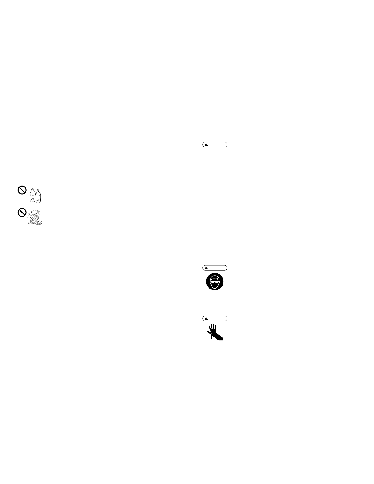
38. AVOID THE DIRECT SUNSHINE
Do not leave the tool or Charger in the direct sunshine for a long time.
39. SECURE THE TABLE FIRMLY, WHERE THE TOOL IS PLACED, SO THAT IT WILL NOT BE
DEFORMED OR TUMBLE DOWN
40. WHEN USING THE MACHINE FOR A SPECIAL PURPOSE OR IN A SPECIAL ENVIRONMENT,
WHICH ARE NOT SPECIFIED IN THIS INSTRUCTION MANUAL, IT IS NECESSARY TO OBSERVE
ADDITIONAL RULES AND REGULATIONS
41. USE ONLY THE MAX AUTHORIZED OPTIONAL PARTS WITH THE TOOL
42. HOLD THE FASTENER DRIVING TOOL DURING THE WORK OPERATION IN SUCH A WAY
THAT NO INJURIES CAN BE CAUSED TO THE HEAD OR TO THE BODY IN THE EVENT OF A
POSSIBLE RECOIL CONSEQUENT UPON A DISRUPTION IN THE ENERGY SUPPLY OR HARD
AREAS WITHIN THE WORKPIECE.
OBSERVE THE FOLLOWING GENERAL CAUTION IN ADDITION TO
THE OTHER WARNINGS CONTAINED IN THIS MANUAL
•
Do not use the tool as a hammer.
•
Do not drop or hit the tool.
•
Do not apply an excessive force.
•
The tool must be used only for the purpose it was designed.
•
Never remove, tamper with the operating controls (e.g., TRIGGER, CONTACT ARM)
•
Keep the tool, the Fuel Cell and the Battery in a dry place out of reach of children when not in
use.
•
Do not use the tool without Safety Warning label.
•
Do not modify the tool from original design or function without approval by MAX CO., LTD.
107
SUSTITUCIÓN DE LA CÉLULA DE COMBUSTIBLE AGOTADA
El gas de chorro combustible sigue permanecendo en la célula de combustible agotada.
ADVERTENCIA:
●
No lanzar la célula de combustible usada en el fuego.
●
Nunca fumar cigarrillo.
●
Nunca respirar el gas.
Deshacerse de todas las células de combustible vacías, en los lugares donde no serán aplastadas,
perforadas, quemadas o descubiertas por los niños.
6. INSTRUCCIONES PARA EL FUNCIONAMIENTO
Se ruega leer la sección titulada “INSTRUCCIONES DE SEGURIDAD”.
1. ANTES DEL FUNCIONAMIENTO
q
Llevar gafas de protección o de trabajo.
w
No insertar la célula de combustible y la batería.
e
Comprobar la estanqueidad de los tornillos.
r
Comprobar el funcionamiento del brazo de contacto y del gatillo para ver si éstos se desplazan sin
sacudida.
t
Insertar la célula de combustible y la batería.
y
Coger la herramienta con el dedo alejado del gatillo, luego empujar el brazo de contacto contra la
parte de trabajo. (La herramienta no debe funcionar).
u
Mantener la herramienta con el brazo de contacto sin la parte de trabajo, luego extraer el gatillo. (La
herramienta no debe funcionar).
i
Retirar la célula de combustible y la batería.
ADVERTENCIA:
ADVERTENCIA:
2. FUNCIONAMIENTO
Llevar gafas de protección o de trabajo.
Un peligro a los ojos existe siempre ya que el polvo puede estar proyectado por el aire que se escapa o
por una punta que vuela hacia arriba en caso de manipulación incorrecta de la herramienta. Por estas
razones, siempre llevar gafas de protección o trabajo cuando se utiliza la herramienta. El dueño y/o el
usuario deben asegurar que una protección apropriado de los ojos está proporcionada.
El equipamiento de protección de los ojos debe cumplir con las exigencias del Instituto de las Normas
Nacionales Americanas, ANSI Z87.1 (Directiva del Consejo 89/686/EEC. del 21 de Dic. de 1989) y
asegurar protección lateral y frontal.
El dueño es responsable para imponer el uso apropriado del equipamiento de protección de los ojos por
el operador de la herramienta y por cualquier otro personal en la zona de trabajo.
NOTA: Gafas sin protección lateral y escudos de cara no aseguran una protección apropriado.
Mantener las manos y el cuerpo alejados de la salida de descarga, cuando se colocan las puntas
ya que hay riesgo de golpear violentamente sus manos o su cuerpo por error.

11
2. SPECIFICATIONS AND TECHNICAL DATA
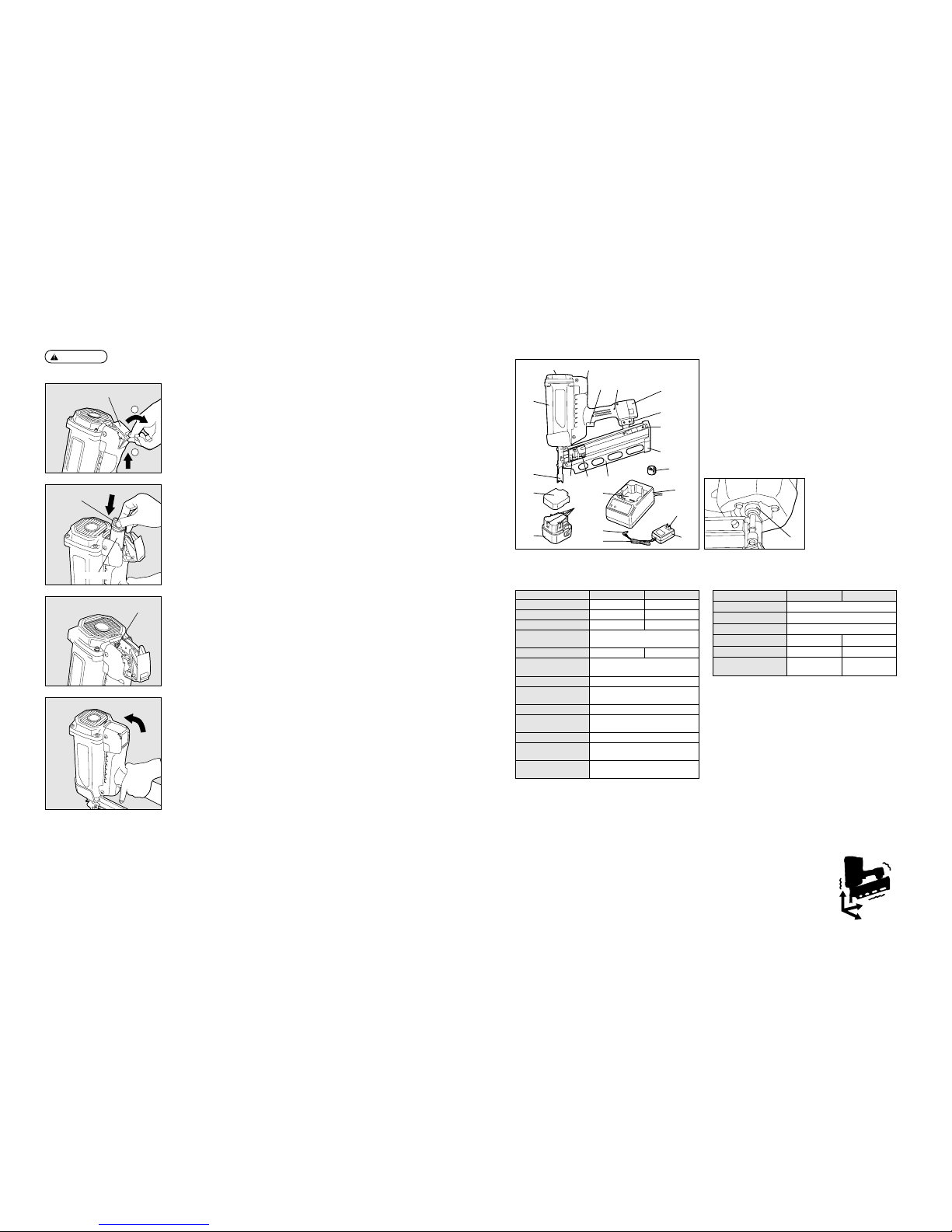
1. NAME OF PARTS
2. TOOL SPECIFICATIONS
PRODUCT NO. GS690RH GS690CH
HEIGHT
15˝ (382 mm) 15-3/8˝ (391 mm)
WIDTH
4-3/8˝ (111 mm) 4-3/8˝ (110 mm)
LENGTH
15˝ (379 mm) 13-3/8˝ (340mm)
WEIGHT
7.8 lbs. (3.5 kg)
(including Fuel Cell and Battery)
LOADING CAPACITY 32 nails (1 strip) 40 nails (1 strip)
BATTERY
Battery JP606H for
MAX Cordless Fastening System
BATTERY CAPACITY
6V DC, 1.5 Ah
CHARGER
Charger JC610M for MAX gas
nailer (AC adapter included)
POWER SOURCE 100-240V AC, 50 or 60 Hz
POWER CONSUMPTION
8VA (10V 800mA)
(Rated output)
CHARGING TIME 150 minutes at maximum
ACCESSORIES
Carrying case, Battery,
Charger
TEMPERATURE RANGE
-5˚C (23˚F) to 49˚C (120˚F)
FOR USE
qew
rt
y
u
i
!1 !2 !3
!8
!9
@0
!0
!5
!6
!7
!4
@1
@4
@2
@3
o
q
Air Filter Cover
w
Fuel Cover
e
Body
r
LED
t
Trigger
y
Battery
u
Hook
i
Nail Stopper
o
Adjustment Dial
(Nail Depth)
!0
Contact Arm
!1
Pusher Holder
!2
Pusher
!3
Magazine
!4
Tail Cover
!5
Pack Cap
!6
Terminal Block
!7
Battery (JP606H)
!8
Battery Setting Hollow
!9
Jack
@0
Power Cord
@1
Charger (JC610M)
@2
Power Plug
@3
AC Adapter
@4
Contact Tip (Option)
3. FASTENER SPECIFICATIONS
PRODUCT NO. GS690RH GS690CH
NAIL LENGTH 2˝ to 3-1/4˝ (50 to 90 mm)
SHANK DIAMETER .113˝ to .131˝ (2.9 to 3.3 mm)
SHANK TYPE Smooth, Ring, Screw
HEAD DIAMETER
.267˝ to .295˝ .256˝ to .303˝
(6.8 to 7.5 mm) (6.5 to 7.7 mm)
COLLATION ANGLE 21 degree 34 degree
HEAD Full round head Clipped head
106
ADVERTENCIA:
AJUSTE DE LA CÉLULA DE COMBUSTIBLE
●
Asegurarse de quitar su dedo del gatillo.
●
No apretar el brazo de contacto contra el objeto.
2
1
q
Levantar y extraer el casquillo de la célula de combustible hacia este lado para
abrirlo.
Casquillo de la célula de combustible
w
Mientras se orienta adelante el injector de chorro de la válvula de chorro (hacia el
casquillo del filtro de aire), ajustar la célula de combustible.
Injector de chorro
e
Cuando se abre el casquillo de la célula de combustible, es posible ver el adaptador
rojo.
Ajustar la válvula de chorro en el adaptador.
Adaptador rojo
r
Poner el casquillo de la célula de combustible sobre la válvula de chorro y bajarlo
para cerrar.
Célula de combustible
NOTE: The triangle symbol marked as “▽” following its tool serial number indicates that safety yoke is equipped with this tool.
4. TECHNICAL DATA
q
NOISE
A-weighted single-event sound power level ------ LWA, 1s, d 103.9 dB
A-weighted single-event emission sound pressure level at work station ------ Lp A, 1s, d 100.5 dB
These values are determined and documented in accordance to EN12549 : 1999.
w
VIBRATION
Vibration characteristic value = 4.04 m/s
2
These values are determined and documented in accordance to ISO 8662-11.
This value is a tool-related characteristic value and does not represent the influence to the hand-armsystem when using the tool. An influence to the hand-arm-system when using the tool will, for example,
depend on the gripping force, the contact pressure force, the working direction, the adjustment of mains
supply, the workpiece, the workpiece support.

12
3. SAFETY DEVICES
The tool is provided with the following safety devices in order to secure safety for nail driving work.
Mechanical Safety Device
This tool is equipped with a FULL SEQUENTIAL ACTVATION MECHANISM. This tool
will not discharge nails unless the Contact Arm and Trigger have been activated
simultaneously. The nails are not discharged by neither simply pulling the Trigger nor
applying the Contact Arm to the nails driving object. The nails are discharged only after
apply the Contact Arm to the object and pulling the Trigger.
Trigger
Contact Arm
CAUTION:
●
Prior to using the tool, be sure to inspect it to see whether the safety devices function
properly. Do not use it if they do not function properly.
Prior to using the tool, check whether the safety devices function properly. With no nails
loaded, install the Battery and Fuel Cell to check.
※
In the following cases, the safety devices are out of order. Never use the tool.
1. An operating sound is emitted by simply pulling the trigger.
2. The tool starts dry-fire operation by simply applying the contact arm to the object.
※
A fan running sound is heard, but this is not a fault.
If any abnormality is found, contact your nearest MAX authorized distributor for
inspection/repairing.
105
5. MANIPULACIÓN DE LA CÉLULA DE COMBUSTIBLE
La célula de combustible presenta una doble estructura; el recipiente interno se ha llenado con gas
combustible líquido mientras que el recipiente externo contiene un gas de chorro (otro gas de presión).
De la misma manera que cuando se presiona un tubo a pasta dentífrica, el gas combustible interior se
expulsa bajo el efecto de la presión de gas de chorro, que se utilizará hasta el final sin derroche.
Gracias a esta estructura, el gas de chorro de combustible en el recipiente externo permanecerá incluso
después de que se ha agotado el gas combustible en el recipiente interno. Por lo tanto, tenga cuidado
cuando se pone la célula de combustible vacía al rechazo.
ADVERTENCIA:
●
Asegurarse de utilizar una célula de combustible exclusivamente concebida para el sistema
de fijación sin cordón MAX.
●
Nunca fumar cigarrillo durante los trabajos de fijación o cuando se utiliza la herramienta con
una válvula de chorro.
●
No retirar la toma de goma del fondo de la célula de combustible, excepto en caso de puesta
al rechazo.
●
No hacer un agujero en la célula de combustible.
●
Tenga cuidado de no respirar el gas, ya que esto puede causar somnolencia, vértigo o
náusea.
●
Nunca ventear el gas hacia una persona.
●
No incinerar o reutilizar la célula de combustible vacía. (Véase la página 107 para la puesta al
rechazo de la célula de combustible)
ADVERTENCIA:
●
Fijar la válvula de chorro correctamente en la célula de combustible.
Fijarlo firmemente hasta que cliquea. A menos que esté fijado correctamente, el gas
combustible no se venteará de la válvula de chorro. Además el gas puede huir, causando así
un peligro.
FIJACIÓN DE LA VÁLVULA DE CHORRO A LA CÉLULA DE COMBUSTIBLE
La válvula de chorro se diseña para ventear una cantidad de gas combustible constante en la cámara
de combustión de la herramienta.
1. Empujar para liberar la válvula. 2. Separar la válvula del casquillo. 3. Alinear los bordes.
4. Empujar el borde antes. 5. Empujar el borde posterior 6. Empujar horizontalmente - él
5. hasta que cliquea. 6. cliquea nuevamente.
Válvula de chorro
WARNING:
●
To avoid accidental firing or double firing, pull the trigger rapidly and firmly.

13
4. HOW TO USE THE BATTERY AND THE CHARGER
WARNING:
●
Be sure to charge MAX JP606H for the tool with MAX JC610M. If charged with other charger,
the Battery could fail to be properly charged as well as get broken, ignited or generate the
heat.
●
Do not put the Battery close to a fire.
●
Do not leave the Battery in the direct sunshine.
●
Do not charge or use the Battery in the wet condition with a liquid such as water, sea water,
milk, soft drink, soap water.
●
Unplug the charger when it is not used.
●
Be sure to charge at 0 to 40°C to avoid the possibility of fire.
●
Do not give a strong shock such as hitting with a hammer, stamping or dropping.
WARNING:
●
In order to prevent short-circuiting, be sure to cover the terminal block (metal section) of the
Battery with the Pack Cap (wind the insulating tape) for recycling.
<Battery cells in Battery Pack>
・
Nominal voltage: 1.2 V/piece
・
Quantity used in 1 pack: 5 pieces
CAUTION:
●
When the Battery has been used up or is not used for a long period, remove it from the
Charger.
●
After setting the Battery in the tool, do not hold it to carry around.
CAUTION:
●
Do not use the out-of-life Battery.
Use of the out-of-life Battery leads to breakdown of the tool body, and charging it causes the
charger to go wrong.
PROPER USE OF BATTERY
q
Fully charge and use up the Battery.
If you repeat charging the Battery while stored electricity still remains more than half the capacity, the
number of nails drivable by each charging could decrease dramatically, shortening the life of the
Battery. It is recommended to use it until the LED of the tool has been illuminated in red, indicating
that the Battery running out of electricity.
w
Use two Batterys alternately.
To ensure the longer life of the Battery, it is recommended to use two of them alternately, one in use
while the other is charging preparing a spare one.
The Battery for the tool uses Ni-MH batteries which are a precious recyclable resource. Once the
Battery runs out of life, take it to your nearest distributor without disposing of it.
Recycling the Ni-MH Battery
104
PRECAUCIÓN:
●
Después de completar los trabajos o cuando la máquina no se utiliza, retirar la caja de
alimentación de la máquina para almacenarla. (Retirar también el cartucho de gas y los
clavos)
Si la herramienta permanece conectada, la energía eléctrica se consumirá durante la puesta
en espera.
En los casos siguientes, realizar la carga lenta con el fin de lograr enteramente el rendimiento de la
herramienta:
・
A la compra de la máquina
・
Cuando la máquina no se utilizó por un mes o aún más
・
Cuando queda claro que se insertan menos clavos aunque se carga la herramienta..
Después de que la lámpara de “Carga completa” se ilumina, dejar la batería en el cargador por aprox.
12 horas.
Por lo que se refiere a la carga lenta

14
Green LED Red LED Status Description
1.
2.
3.
4.
5.
6.
HOW TO USE THE CHARGER
The special purpose charger JC610M has the LEDs (green, red) which indicate the status of the charger
and Battery.
The following cases are considered to be the troubles. Replace the charger and Battery with new ones.
●
The green LED is not turned on if the power plug of the charger is plugged into a 100-240 V AC (for
household use) plug socket. (With the Battery unset)
※
Check with another electric appliance to see whether electricity is available at the plug socket.
●
Neither green nor red LED is turned on or blinks if the Battery is set in the Charger.
●
The green LED is not turned on 150 minutes after the red one has been turned on.
●
The red LED is not turned on if the Battery is set in the charger.
Troubles of Charger and Battery
○
ON
●
OFF
Power-on
The charger has been plugged in. (Power-on status:
Battery unset)
●
OFF
○
ON
Charging The Battery is being charged.
○
ON
●
OFF
Charge Completed The Battery has been completed charged.
Blinking Blinking
High temparature
alarm
The Battery is hot. (Remove it from the Charger and
cool it down for a while before charging.)
○
ON
○
ON
Battery alarm The Battery is defective. (Replace it with a new one)
Blinking
○
ON
Battery high
temparature alarm
The Battery is defective and hot. (Replace it with a
new one.)
103
ADVERTENCIA:
CÓMO CARGAR
●
Cargar la batería a la tensión indicada.
Asegurarse de cargar correctamente a partir de una toma de c.d. de 100~240 V (para el uso
doméstico). El uso de una tensión no indicada causará no sólo un problema, sino también un
riesgo de peligro.
●
Manejar el cable de alimentación con cuidado.
No utilizar a un cargabatería cuyo cable de alimentación está dañado.
●
Utilizar una toma de alimentación apropriada.
El uso de una toma floja causará un accidente debido a un recalentamiento. Si esto se
produce, utilizar una toma apropriada.
q
Si la batería se utiliza una vez, luego se ajusta en el cuerpo de la herramienta,
retirarla de la herramienta. Mientras se mantiene firmemente el cuerpo de la
herramienta, apretar los pestillos sobre ambos lados de la batería con sus dedos
para retirarla.
Batería
w
Insertar la toma jack del adaptador de c.d. en el cargabatería, luego conectar la
clavija a la toma de alimentación.
La DEL verde se ilumina para señalar el estado de la alimentación en contacto.
DEL verde
Cargabatería
Adaptador de alimentación
de c.a., 100~240 V
Pestillo
PRECAUCIÓN:
●
No intentar cargar la batería que se ha cargada enteramente. La duración de servicio de la
batería corre el riesgo de acortarse.
e
Cargar la batería.
1. Ajustar la batería firmemente en el cargador.
2. Una vez que se coloca en el cargabatería, la carga comenzará automáticamente. La
DEL roja se ilumina para señalar que la carga está en curso.
3. El tiempo de carga máximo es de aprox. 150 minutos. El tiempo de carga depende
de la temperatura, la tensión de alimentación o la capacidad residual de la batería.
Una vez que la carga se completa enteramente, la DEL verde se iluminará para
señalar que se ha realizado la carga. Si la batería enteramente cargada se coloca
nuevamente en el cargabatería, la DEL roja se iluminará otra vez, indicando así que
está en fase de carga. Esto no es anormal. Después un cierto período de tiempo, la
DEL verde se iluminará para indicar el final de la carga.
r
La DEL verde iluminada señala el final de la carga.
1. Manteniendo el cargabatería, retirar la batería.
2. Desconectar la clavija de alimentación del adaptador de c.a. de la toma de
alimentación.
Se completa así la carga.
Batería
DEL roja
Cargabatería
Tomada de alimentación
de c.a., 100~240 V
15
WARNING:
HOW TO CHARGE
●
Charge the Battery at the specified voltage.
Be sure to charge from a 100-240 V AC (for household use) plug socket. Use of the nonspecified voltage not only causes a trouble, but also is dangerous.
●
Handle the power cord with care.
Do not use the Charger whose power cord is damaged.
●
Use a proper plug socket.
Use of the rickety or slack plug socket causes an accident due to overheat. If this is the case,
use another proper one.
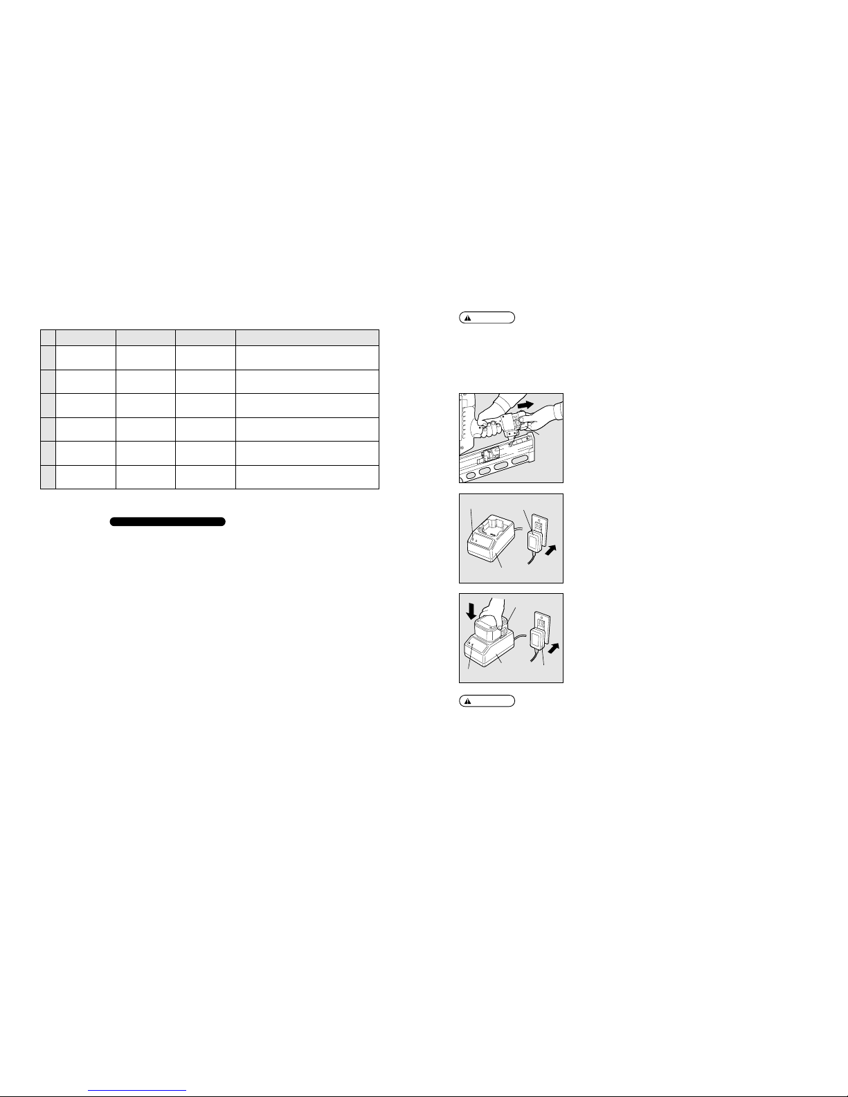
q
If the Battery is used up, remove it from the tool.
Firmly holding the tool body, press the latches on both side of the Battery with your
fingers to remove.
Battery
w
Insert the AC adapter’s jack into the Charger and plug the power plug into a
plug socket.
The green LED is turned on to inform you of the power-on status.
Green LED
Charger
100-240 V
AC Power Adapter
Latch
102
DEL verde DEL roja Estado Descripción
1.
2.
3.
4.
5.
6.
CÓMO UTILIZAR EL CARGABATERÍA
El cargabatería de aplicación especial JC610M presenta las DEL (verde y roja) que indican el estado
del cargabatería y la batería.
Los casos siguientes representan problemas. Sustituir al cargabatería y la batería por nuevas partes.
●
La DEL verde no se ilumina si la toma de alimentación del cargador se conecta a una toma de c.d.
de 100~240 V (para uso doméstico) (con la batería no ajustada).
※
Comprobar con otro aparato eléctrico para ver si la electricidad está presente a la toma de
alimentación.
●
Ni la DEL verde, ni la roja se iluminan o parpadean si la batería se coloca en el cargabatería.
●
La DEL verde no se ilumina 150 minutos después de que se haya iluminado la DEL roja.
●
La DEL roja no se ilumina si la batería se coloca en el cargabatería.
Problemas del cargabatería y la batería
○
ON (conectado)
●
OFF
(desconectado)
Alimentación en
contacto
Se ha conectato el cargador. (Estado de la
alimentación en contacto: batería no ajustada)
●
OFF
(desconectado)
○
ON (conectado)
Carga La batería está en fase de carga.
○
ON (conectado)
●
OFF
(desconectado)
Carga completada Se ha cargado correctamente la batería.
Parpadea Parpadea
Alarma de alta
temperatura
La batería es caliente. (Retirarla del cargabatería y dejarla
enfriarse por un determinado período de tiempo antes de cargar).
○
ON (conectado)○ON (conectado)
Alarma de batería
La batería es defectuosa. (Sustituirla por una
nueva).
Parpadea
○
ON (conectado)
Alarma de alta
temperatura de la batería
La batería es defectuosa y caliente. (Sustituirla por
una nueva).
CAUTION:
●
Do not try to charge the Battery which has been fully charged. The life of the Battery could be
shortened.
e
Charge the Battery.
1. Set the Battery firmly in the charger.
2. Once it is set in the charger, charging will start automatically. The red LED is turned
on to inform you that charging is under way.
3. The maximum charging time is approx. 150 minutes. The charging time depends on
the temperature, supply voltage or remaining battery capacity. Once charging is fully
completed, the green LED will be illuminated to inform you that charging has been
completed. If the fully charged Battery is set in the charger again, the red LED will be
turned on again, indicating that it is being charged. This is not an abnormality. After a
while, the green LED will be turned on to indicate completion of charging.
r
The Illuminated Green LED Indicates completion of charging.
1. Holding down the charger, remove the Battery.
2. Disconnect the AC adapter’s power plug from the plug socket.
Now Charging is complete.
Battery
Red LED
Charger
100-240 V
AC Power Plug
16 101
4. CÓMO UTILIZAR LA BATERÍA Y EL CARGABATERÍA
ADVERTENCIA:
●
Asegurarse de cargar correctamente MAX JP606H para la herramienta MAX JC610M. Si es
cargada por otro cargabatería, la batería podría no cargar correctamente o se romperá,
causará un incendio o producirá calor.
●
No poner la batería cerca de un fuego.
●
No exponer la batería directamente al sol.
●
No cargar o utilizar la batería en condición húmeda en presencia de líquido como agua, agua
de mar, leche, bebida no alcóholica, agua jabonosa.
●
Desconectar el cargador cuando no se utiliza.
●
Asegurarse de cargar correctamente a la temperatura de 0˚C (32˚F) a 40˚C (104˚F) para evitar
cualquier riesgo de incendio.
●
No aplicar un choque fuerte con un martillo, por estampado o caída.
ADVERTENCIA:
●
Con el fin de evitar cualquier riesgo de cortocircuito, cubrir el bloque de bornes (sección de
metal) de la batería con el casquillo de paquete (envolver la banda aislante) para el reciclaje.
<Baterías utilizadas>
・
Tensión nominal: 1,2 V/pieza
・
Cantidad utilizada en 1 paquete: 5 piezas
PRECAUCIÓN:
●
Cuando la batería está agotada o no se utiliza por un largo período de tiempo, retirarla del
cargabatería.
●
Después del ajuste de la batería en la herramienta, no mantenerla para transportarlo.
PRECAUCIÓN:
●
No utilizar la batería cuya duración de servicio expiró.
El uso de una batería cuya duración de servicio expiró resultará en una avería del cuerpo de
la herramienta, y una nueva carga dañará el cargabatería.
USO APROPRIADO DE LA BATERÍA
q
Cargar y utilizar la batería completamente.
Si se repite la carga de la batería mientras que la electricidad acumulada permanece siempre por
más de la mitad de la capacidad, el número de clavos que puden ser colocados a cada carga podría
disminuir claramente, acortando así la duración de servicio de la batería. Recomendamos utilizar la
batería hasta que la DEL de la herramienta esté iluminada en rojo, indicando de este modo una
ausencia de electricidad.
w
Utilizar dos baterías alternativamente.
Para asegurar una duración de servicio más larga de la batería, recomendamos utilizar dos baterías
alternativamente, previendo al mismo tiempo una batería de servicio.
La alimentación de la herramienta utiliza baterías de níquel-hidrógeno que constituyen un recurso de
reciclaje importante. Una vez que la duración de servicio de la batería expira, llevarla al distribuidor más
cercano a su zona de residencia para ponerlo al rechazo.
Reciclaje de la batería níquel-hidrógeno
CAUTION:
●
After completing your work or when the tool is not used, be sure to remove the Battery Pack
from the tool to store it. (Remove the Fuel Cell and nails as well)
If it is left connected, the electric power will be consumed in the standby state.
In the following cases the Battery Pack must be charged for 12 HOURS to reach top performance:
・
Upon purchasing the tool.
・
When the tool has not been used for 1 month or longer.
・
When it is clear that you can drive less nails even when fully charged.
After the Charge Complete lamp has been turned on, leave the Battery set in the Charger for about
another 12 hours.
Preventing the Battery Pack from becoming inactive
17100
3. DISPOSITIVOS DE SEGURIDAD
La herramienta se equipa de los dispositivos de seguridad siguientes con el fin de asegurar una buena
seguridad para los trabajos de instalación de los clavos.
Dispositivo mecánico de seguridad
Esta herramienta se equipa de un MECANISMO DE ACCIÓN SECUENCIAL
COMPLETA. Esta herramienta permite evitar la descarga de clavos a menos que el
brazo de contacto y el gatillo se hayan impulsado simultáneamente. Los clavos no se
descargan ni extrayendo simplemente el gatillo, ni aplicando el brazo de contacto al
objeto para la instalación de los clavos. Los clavos se descargan solamente después
de aplicar el brazo de contacto al objeto y extraer el gatillo.
Gatillo
Brazo de contacto
PRECAUCIÓN:
●
Antes de utilizar la herramienta, asegurarse de comprobarlo para ver si los dispositivos de
seguridad funcionan correctamente. No utilizarla si los dispositivos no funcionan de modo
apropriado. Antes de utilizar la herramienta, comprobar si los dispositivos de seguridad
funcionan correctamente. Sin los clavos cargados, instalar la célula de combustible y la
batería para controlar.
※
En los casos siguientes, los dispositivos de seguridad no funcionan correctamente, entonces
nunca utilizar la herramienta.
1. Se emite un ruido de funcionamiento extrayendo simplemente el gatillo.
2. La herramienta comienza la operación de disparo a vacío aplicando simplemente el brazo
de contacto al objeto.
※
Se oye un ruido de funcionamiento del ventilador, pero esto no es un problema.
Si se observa un hecho anormal, consulte al distribuidor autorizado MAX más cercano a su
zona de residencia para efectuar la inspección o reparación de la herramienta.
5. HANDLING OF FUEL CELL
The Fuel Cell is double structured; the inner container has been filled with a liquid fuel gas and the outer
one with a propellant gas (another pressurized gas).
Like squeezing a toothpaste tube, the inner fuel gas is pushed out by the pressure of the propellant gas,
thus being used up to the last without wasting it. Because of this structure, the combustible propellant
gas in the outer container remains even after the fuel gas in the inner container has been used.
Therefore, utmost care should be taken when disposing the empty Fuel Cell.
WARNING:
●
Be sure to use the Fuel Cell exclusively designed for the MAX Cordless Fastening System.
●
Never smoke a cigarette when attaching or operating a jet valve.
●
Do not remove a rubber plug from the bottom of the Fuel Cell except at disposal.
●
Do not make a hole in the Fuel Cell.
●
Be careful not to breathe in the gas.
Breathing in the gas could cause sleepiness, dizziness or nausea.
●
Never jet the gas to the human body.
●
Do not incinerate or recycle the empty Fuel Cell.
(See Page 19 for disposal of the Fuel Cell)
WARNING:
●
Attach the metering valve properly to the Fuel Cell.
Attach it firmly until it has “clicked.”
Unless it is properly attached, the fuel gas will not be jetted from the metering valve. Also, the
gas could leak, causing danger to you.
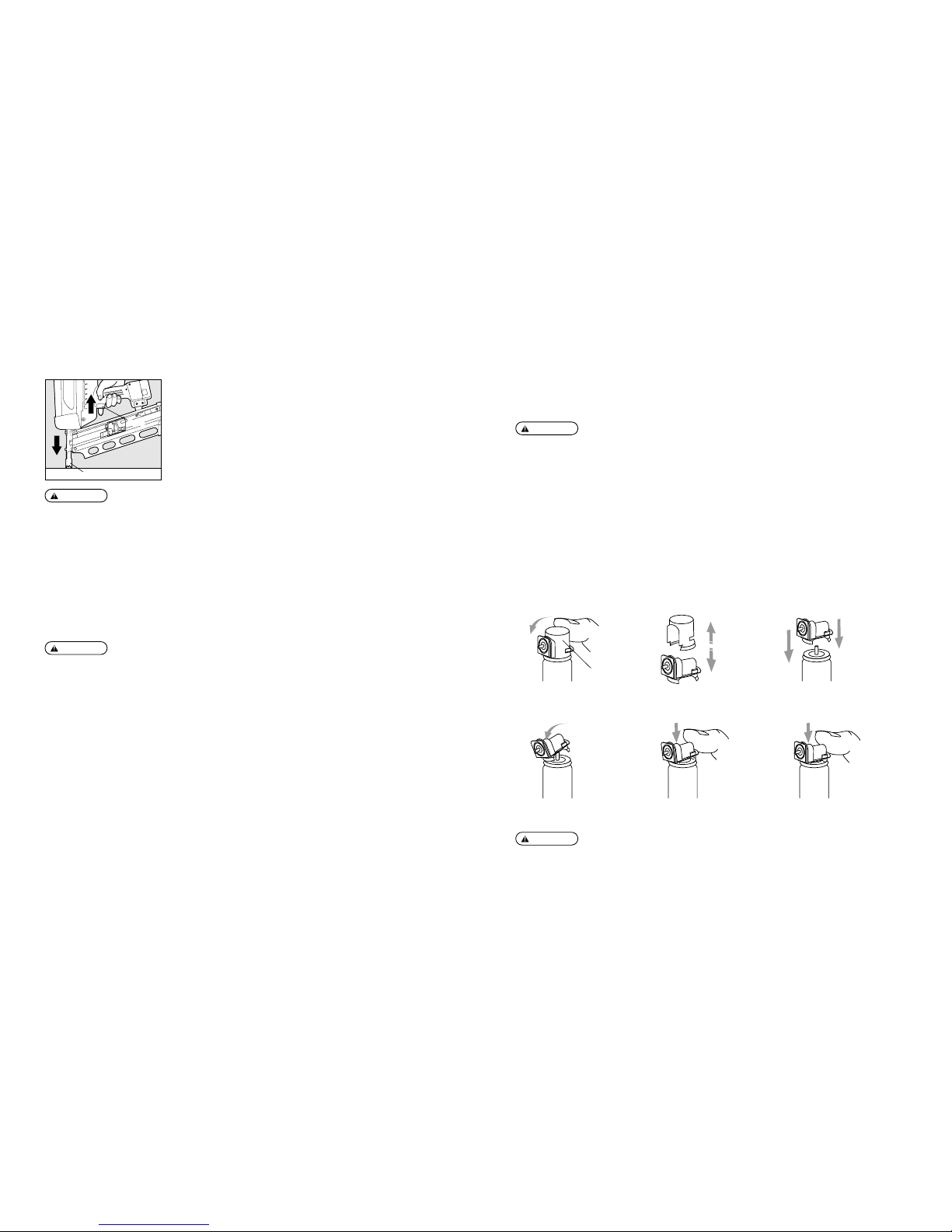
ATTA CHING THE METERING VALVE TO THE FUEL CELL
The metering valve is designed to jet a constant amount of fuel gas into the combustion chamber of the
tool.
1. Push to remove the valve. 2. Detach the valve from the cap. 3. Align the edges.
4. Push in the front edge 5. Push in the rear edge until it 6. Push in horizontally. It clicks again.
5. has clicked.
Metering Valve
●
Con el fin de evitar el disparo accidental o doble, tirar el disparador rápida y firmemente.
ADVERTENCIA:
18 99
2. CARACTERÍSTICAS Y DATOS TÉCNICOS
1. NOMBRE DE LAS PARTES
2. CARACTERÍSTICAS DE LA HERRAMIENTA
N˚ DE PRODUCTO GS690RH GS690CH
ALTURA 382 mm 391 mm
ANCHURA 111 mm 110 mm
LONGITUD 379 mm 340 mm
PESO
3.5 kg (7.8 lbs.)
(incluidas la célula de combustible y la batería)
CAPACIDAD DE CARGA
32 clavos/banda 40 clavos/banda
BATERÍA
Batería JP606H para sistema de
fijación sin cordón MAX
CAPACIDAD DE LA BATERÍA
6 V c.d., 1.5 aH
CARGADOR DE PUNTAS
Cargador JC610M para clavadoras de
gas MAX (incluido adaptador c.a).
FUENTE DE ALIMENTACIÓN
100~240 V, c.a., 50 ó 60 Hz
CONSUMO ELÉCTRICO
8 VA (10 V 800 mA)
(salida nominal)
TIEMPO DE CARGA 150 minutos al máximo
ACCESORIOS
Estuche para el transporte,
batería, cargabatería
INTERVALO DE TEMPERATURA
-5˚C (23˚F) a 49˚C (120˚F)
PARA EL USO
qew
rt
y
u
i
!1 !2 !3
!8
!9
@0
!0
!5
!6
!7
!4
@1
@4
@2
@3
o
q
Casquillo de filtro de aire
w
Casquillo de combustible
e
Cuerpo
r
DEL
t
Gatillo
y
Batería
u
Gancho
i
Bloque de clavos
o
Cuadrante de ajuste
!0
Brazo de contacto
!1
Soporte de botón
!2
Botón
!3
Cargador de puntas
!4
Casquillo de cola
!5
Casquillo de paquete
!6
Bloque de bornes
!7
Batería (JP606H)
!8
Cavidad de ajuste de la
batería
!9
Toma jack
@0
Cable de alimentación
@1
Cargabatería (JC610M)
@2
Toma de alimentación
@3
Adaptador CA
@4
Caperuza de contacto
(Opción)
3. CARACTERÍSTICAS DE LAS PUNTAS
N˚ DE PRODUCTO GS690RH GS690CH
LONGITUD DE CLAVO
50 a 90 mm
DIÁMETRO DE PIERNA
2.9 a 3.3 mm
TIPO DE PIERNA Tornillo de anillo liso
DIÁMETRO DE LA CABEZA
de 6.8 a 7.6 mm. de 6.5 a 7.7 mm.
ÁNGULO DE COLACIÓN
21 grados 34 grados
CABEZA
Cabeza redonda
Cabeza acortada
llena
WARNING:
SETTING THE FUEL CELL
●
Be sure to release your finger from the Trigger.
●
Do not press the Contact Arm against the object.
2
1
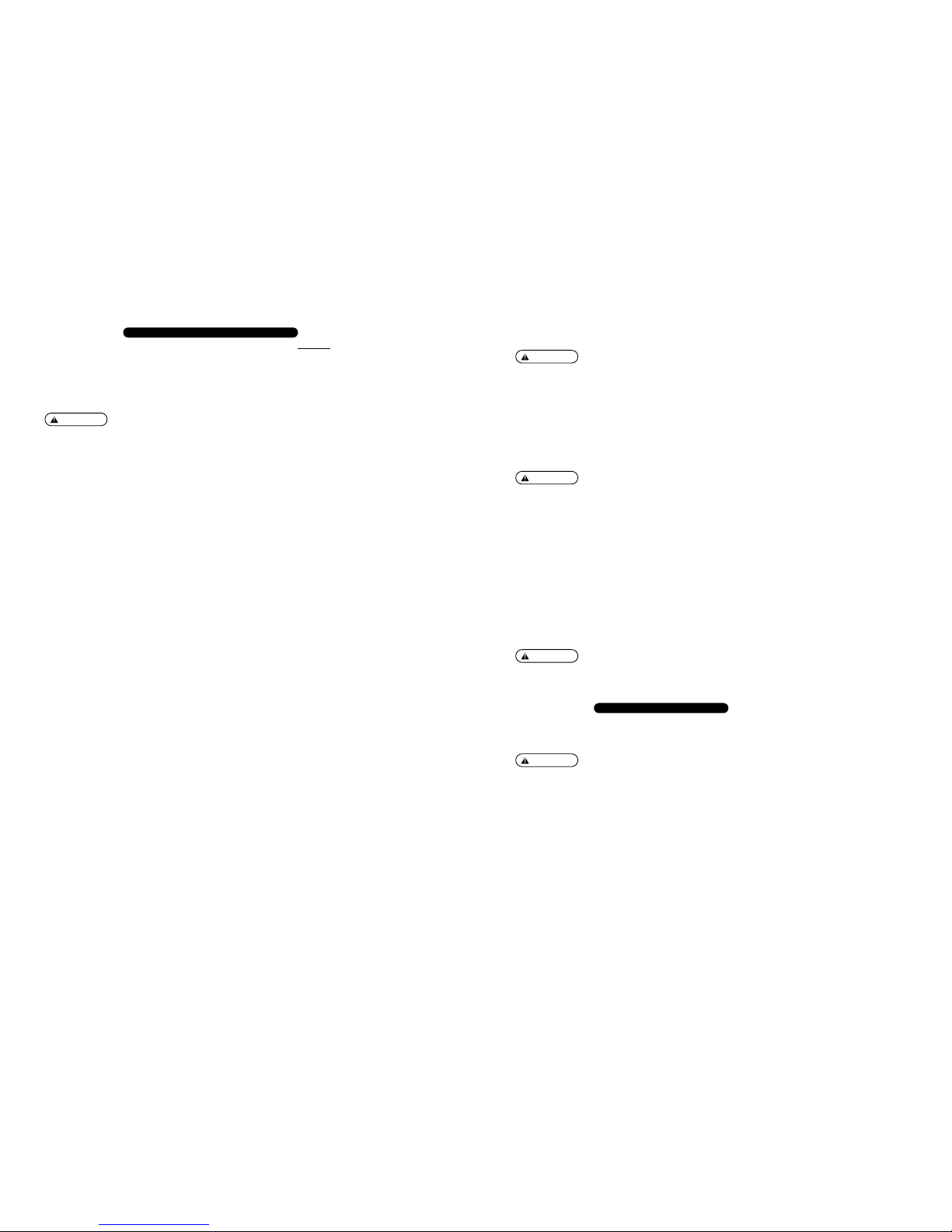
q
Push up and pull the Fuel Cover to this side to open it.
Fuel Cover
w
Directing the Jet Nozzle of the Metering Valve forward (toward the Air Filter Cover),
set the Fuel Cell.
Jet Nozzle
e
When you open the Fuel Cover, you can see a Red Adapter.
Fit the Jet Nozzle into this adapter.
Red Adapter
r
Put the Fuel Cover over the metering valve and push it down to latch.
Fuel Cell
NOTA: El símbolo de triángulo “▽” que sigue su número de serie de herramienta indica que esta herramienta se equipa de un
bloque de seguridad.
4. DATOS TÉCNICOS
q
NIVEL DE RUIDO
Nivel de potencia acústica por impulsos A ------ LWA, 1s, d 103.9dB
Nivel de intensidad acústica por impulsos A ------ Lp A, 1s, d 100.5 dB
en el puesto de trabajo
La determinación y documentación de estos valores se realiza según EN12549: 1999.
w
VIBRACIONES
Indice de vibraciones = 4.04 m/s
2
Estos valores se determinan y se documentan de acuerdo con ISO 8662-11.
Este valor es un valor característico relacionado a la herramienta y no representa la influencia al sistema
mano-brazo al usar la herramienta. Una influencia al sistema mano-brazo cuando se usa la herramienta,
por ejemplo, dependerá de la fuerza de agarre, la fuerza de presión de contacto, la dirección de trabajo,
el ajuste del suministro de aire principal, el lugar de trabajo, el soporte de los objetos de trabajo.
 Loading...