

Max 1500 PRO, 2200 PRO, F18 PRO Installation Manual

Installation Guide for
MAX 1500 PRO/2200 PRO/f18 PRO
MATRIX III
CONFORMS TO UL STD 325
MAX 1500 PRO/2200 PRO UL CLASS - I, II, III, IV
MAX F18 PRO UL CLASS - III, IV ONLY
CERTIFIED TO CAN/CSA STD
C22.2 NO. 247
Slide Gate Operators
SAFETY SENSORS REQUIRED
Version 7a
Residential/Commercial
Brushless DC Slide Gate Operators
Made in USA
www.max.us.com
4009963

ul 325 compliant installation
requirements
a) Install the gate operator only when:
a) N’installez l’ouvre-barrière que si :
1) The operator is appropriate for the construction of the gate and the usage Class of the gate,
1) l’ouvre-barrière est approprié pour la structure et la classe d’utilisation de la barrière;
2) All openings of a horizontal slide gate are guarded or screened from the bottom of the gate to a minimum of 1.83 m (6 ft) above the ground
to prevent a 57.2 mm (2-1/4 inch) diameter sphere from passing through the openings anywhere in the gate, and in that portion of the
adjacent fence that the gate covers in the open position,
2) toutes les ouvertures de la barrière coulissante sont protégées ou grillagées du bas de la porte jusqu’à unminimum de 1,83 m (6 pi) du sol
si bien qu’une sphère de 57,2 mm (2 1/4 po) de diamètre ne peut passer par une ouverture au niveau de la barrière et de la portion de la
clôture adjacente que la barrière couvre en position ouverte;
3) All exposed pinch points are eliminated or guarded, and
3) tous les points de pincement sont éliminés ou protégés;
4) Guarding is supplied for exposed rollers.
4) des protections sont fournies pour les galets exposés.
b) The operator is intended for installation only on gates used for vehicles. Pedestrians must be supplied with a separate access opening. The
pedestrian access opening shall be designed to promote pedestrian usage. Locate the gate such that persons will not come in contact with the
vehicular gate during the entire path of travel of the vehicular gate.
b) L’ouvre-barrière est destiné à n’être installé que sur des barrières utilisées pour les véhicules. Il faut fournir une autre voie d’accès aux
piétons. La voie d’accès pour les piétons doit être conçue pour favoriser le passage des piétons. Placez la barrière de sorte que personne ne
puisse entrer en contact avec la barrière pour les véhicules sur l’ensemble de sa trajectoire.
c) The gate must be installed in a location so that enough clearance is supplied between the gate and adjacent structures when opening and
closing to reduce the risk of entrapment. Swinging gates shall not open into public access areas.
c) Pour réduire les risques de coincement lors de l’ouverture et de la fermeture, la barrière doit être installée dans un endroit où la barrière et
les structures avoisinantes sont suffisamment éloignées l’une de l’autre. Les barriers battantes ne doivent pas ouvrir dans une zone d’accès
public.
d) The gate must be properly installed and work freely in both directions prior to the installation of the gate operator. Do not over-tighten the
operator clutch or pressure relief valve to compensate for a damaged gate.
d) La barrière doit être bien installée et fonctionner librement dans les deux directions avant d’entreprendre l’installation de l’ouvre-barrière.
Ne serrez pas trop l’embrayage ou la soupape de surpression de l’ouvre-barrière pour compenser une barrière endommagée.
e) For gate operators utilizing Type D protection:
e) Pour les ouvre-barrières qui utilisent des protections de type D :
1) The gate operator controls must be placed so that the user has full view of the gate area when the gate is moving,
1) les commandes de l’ouvre-barrière doivent être placées de sorte que l’utilisateur voit l’ensemble de la zone de la barrière lorsque cette
dernière est en mouvement;
2) The placard as required by 62.1.6 shall be placed adjacent to the controls,
2) l’étiquette requise selon la clause 62.1.6 doit être placée à côté des commandes;
3) An automatic closing device (such as a timer, loop sensor, or similar device) shall not be employed, and
3) un dispositif de fermeture automatique (comme une minuterie, une boucle de détection ou un dispositif similaire) ne doit pas être utilisé;
4) No other activation device shall be connected.
4) aucun autre appareil d’activation ne doit être connecté.
f) Controls intended for user activation must be located at least 1.83 m (6 ft) away from any moving part of the gate and where the user is
prevented from reaching over, under, around or through the gate to operate the controls.
f) Les commandes destinées à l’activation par l’utilisateur doivent être situées à au moins 1,83 m (6 pi) des pieces mobiles de la barrière et à
un endroit où l’utilisateur ne peut pas atteindre les commandes par le dessus, par le dessous, par les côtés et au travers de la barrière.
Exception: Emergency access controls only accessible by authorized personnel (e.g. fire, police, EMS) may be placed at any location in the
line-of-sight of the gate.
Exception : Les commandes d’accès d’urgence accessibles au personnel autorisé seulement (p. ex. pompier, policier, SMU) peuvent être
placées à tout endroit dans le champ de visibilité de la barrière.
UL 325 2018 Standard - MAX 1500 PRO/2200 PRO/F18 PRO Matrix III Instal
2
Safety - 1
l Version 7a

ul 325 compliant installation
requirements continued
g) The Stop and/or Reset button must be located in the lineof-sight of the gate. Activation of the reset control shall not cause the operator to
start.
g) Le bouton d’arrêt, le bouton de réenclenchement ou ces deux boutons doivent être situés dans le champ de visibilité de la barrière.
L’activation des commandes de réenclenchement ne doit pas mettre en marche l’ouvrebarrière.
h) A minimum of two (2) WARNING SIGNS shall be installed, in the area of the gate. Each placard is to be visible by persons located on the
side of the gate on which the placard is installed. Also see 62.1.1.
h) Au moins deux panneaux de mise en garde doivent être installés dans la zone de la barrière. Chaque étiquette doit être visible des
personnes situées de chaque côté de la barrière sur laquelle l’étiquette est installée. Voir aussi la clause 62.1.1.
i) For gate operators utilizing a non-contact sensor in accordance with 32.1.1:
i) Pour les ouvre-barrières qui fonctionnent avec des capteurs sans contact conformément à la clause 32.1.1 :
1) See instructions on the placement of non-contact sensors for each Type of application,
1) Voir les instructions sur le positionnement des capteurs sans contact pour chaque type d’utilisation.
2) Care shall be exercised to reduce the risk of nuisance tripping, such as when a vehicle, trips the sensor while the gate is still moving, and
2) Des précautions doivent être prises pour réduire les risques de déclenchement inutile, comme lorsqu’un véhicule déclenche le capteur alors
que la barrière est encore en mouvement.
3) One or more non-contact sensors shall be located where the risk of entrapment or obstruction exists, such as the perimeter reachable by a
moving gate or barrier.
3) Un capteur sans contact ou plus doit être situé où il existe un risque de coincement ou d’obstruction, comme dans l’espace que peut
occuper la barrière lorsqu’elle est en mouvement.
j) For a gate operator utilizing a contact sensor in accordance with 32.1.1:
j) Pour les ouvre-barrières qui fonctionnent avec des capteurs de contact conformément à la clause 32.1.1 :
1) One or more contact sensors shall be located where the risk of entrapment or obstruction exists, such as at the leading edge, trailing edge,
and postmounted both inside and outside of a vehicular horizontal slide gate.
1) Au moins un capteur de contact doit être situé où il existe un risque de coincement ou d’obstruction, comme sur le bord d’ouverture, sur le
bord de fermeture et sur les poteaux montés sur l’intérieur ou l’extérieur d’une barrière coulissante pour véhicules.
2) One or more contact sensors shall be located at the bottom edge of a vehicular vertical lift gate.
2) Au moins un capteur de contact doit être situé sur le bord inférieur d’une barrière levante pour véhicules.
3) One or more contact sensors shall be located at the pinch point of a vehicular vertical pivot gate.
3) Au moins un capteur de contact doit être situé au point de pincement d’une barrière à pivot vertical pour véhicules.
4) A hardwired contact sensor shall be located and its wiring arranged so that the communication between the sensor and the gate operator is
not subjected to mechanical damage.
4) Un capteur de contact doit être installé et câblé de sorte à éviter que la communication entre le capteur et l’ouvrebarrière soit gênée par des
dommages mécaniques.
5) A wireless device such as one that transmits radio frequency (RF) signals to the gate operator for entrapment protection functions shall be
located where the transmission of the signals are not obstructed or impeded by building structures, natural landscaping or similar obstruction. A wireless device shall function under the intended end-use conditions.
5) Un dispositif sans fil, comme un appareil qui transmet des signaux de radiofréquence (RF) à l’ouvre-barrière pour prévenir le coincement,
doit être situé à un endroit où la transmission des signaux ne sera pas obstruée ou gênée par des structures, des arbres ou d’autres obstacles
similaires. Un dispositif sans fil doit fonctionner selon les conditions d’utilisation finale prévues.
6) One or more contact sensors shall be located on the inside and outside leading edge of a swing gate. Additionally, if the bottom edge of a
swing gate is greater than 152 mm (6 inches) but less than 406 mm (16 inches) above the ground at any point in its arc of travel, one or more
contact sensors shall be located on the bottom edge.
6) Au moins un capteur de contact doit être situé sur les bords d’ouverture intérieur et extérieur d’une barrière battante. De plus, si le dessous
d’une barrière battante est situé à plus de 152 mm (6 po) mais à moins de 406 mm (16 po) du sol à l’un des points de sa trajectoire, au moins
un capteur de contact doit être situé sur le bord inférieur.
7) One or more contact sensors shall be located at the bottom edge of a vertical barrier (arm).
7) Au moins un capteur de contact doit être situé sur le bord inférieur d’une barrière verticale (bras).
UL 325 2018 Standard - MAX 1500 PRO/2200 PRO/F18 PRO Matrix III Instal
3
Safety - 2
l Version 7a

important safety information
IMPORTANT SAFETY INSTRUCTIONS WARNING – To reduce the risk of injury or death:
INSTRUCTIONS DE SÉCURITÉ IMPORTANTES AVERTISSEMENT – Pour réduire les risques de blessures et de mort :
1. READ AND FOLLOW ALL INSTRUCTIONS.
1. LISEZ ET SUIVEZ TOUTES LES INSTRUCTIONS.
2. Never let children operate or play with gate controls. Keep the remote control away from children.
2. Ne laissez jamais les enfants manoeuvrer les commandes de la barrière ou jouer avec celles-ci. Laissez la télécommande hors de la portée
des enfants.
3. Always keep people and objects away from the gate. NO ONE SHOULD CROSS THE PATH OF THE MOVING GATE.
3. Tenez toujours à l’écart de la barrière toute personne ou tout objet avoisinant. IL NE FAUT JAMAIS PASSER DANS LA TRAJECTOIRE D’UNE
BARRIÈRE EN MOUVEMENT.
4. Test the gate operator monthly. The gate MUST reverse on contact with a rigid object or stop when an object activates the non-contact
sensors. After adjusting the force or the limit of travel, retest the gate operator. Failure to adjust and retest the gate operator properly can
increase the risk of injury or death.
4. Vérifiez le fonctionnement de l’ouvre-barrière une fois par mois. Le sens de la course DOIT s’inverser lorsque la barrière entre en contact
avec un objet dur ou la barrière DOIT s’arrêter lorsqu’un objet active les capteurs sans contact. Vérifiez à nouveau l’ouvre-barrière après tout
réglage de la force de déclenchement ou du seuil de fin de course. Un réglage incorrect de l’ouvre-barrière ou l’omission de vérifier à nouveau
le fonctionnement de l’ouvre-barrière peut causer des blessures, voire la mort.
5. Use the emergency release only when the gate is not moving.
5. Ne déclenchez le dispositif de désaccouplement d’urgence que lorsque la barrière ne bouge pas.
6. KEEP GATES PROPERLY MAINTAINED. Read the user’s manual. Have a qualified service person make repairs to gate hardware.
6. ASSUREZ-VOUS QUE LA BARRIÈRE EST CORRECTEMENT ENTRETENUE. Lisez le manuel de l’utilisateur. Confiez la réparation du matériel
de la barrière à un technicien qualifié.
7. The entrance is for vehicles only. Pedestrians must use separate entrance.
7. La voie d’accès est réservée aux véhicules seulement. Les piétons doivent utiliser une voie d’accès différente.
8. SAVE THESE INSTRUCTIONS.
8. CONSERVEZ CES INSTRUCTIONS.
4
Safety - 3
UL 325 2018 Standard - MAX 1500 PRO/2200 PRO/F18 PRO Matrix III Instal
l Version 7a
ul 325 model classifications
AUTHORIZED
PERSONNEL
ONLY
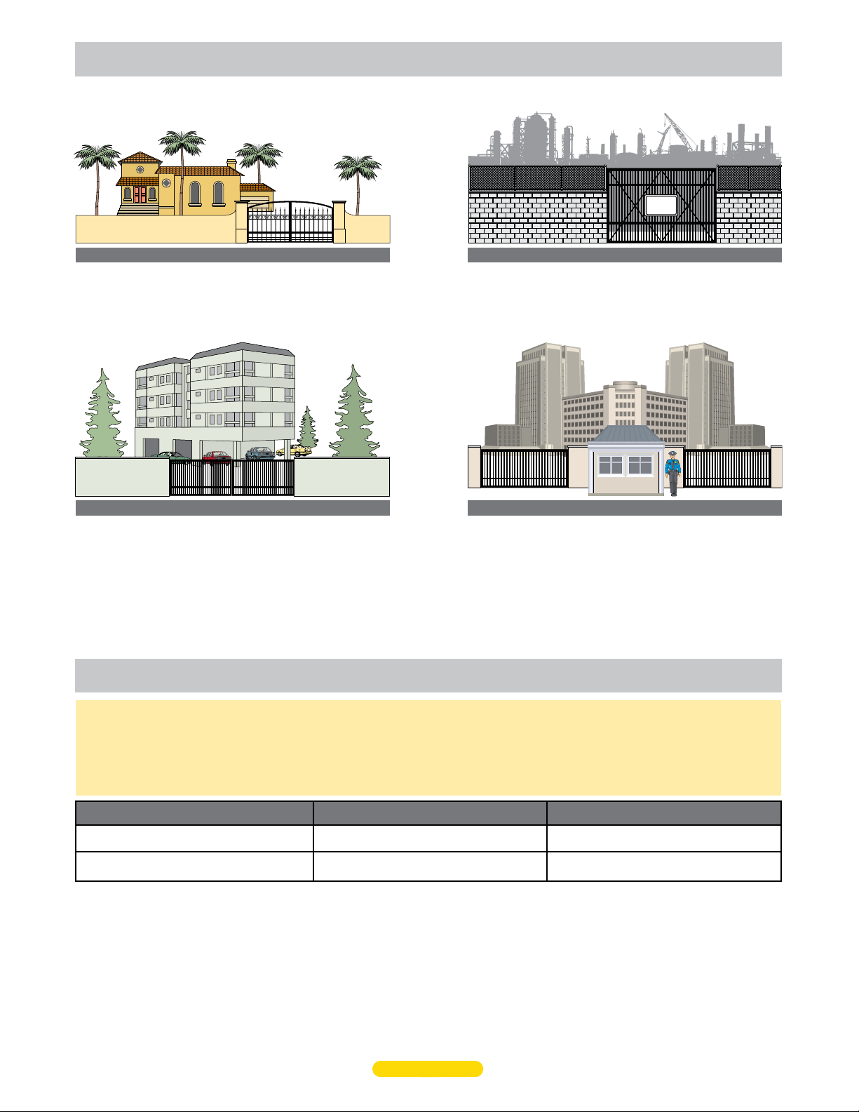
CLASS I
Residential Vehicular Gate Operator - A vehicular gate operator
(opener or system) intended for use in a home of one to four
single family dwellings, or a garage or parking area associated
therewith.
CLASS II
Commercial/General Access Vehicular Gate Operator - A
vehicular gate operator (opener or system) intended for use in
a commercial location or building such as a multi-family
housing unit (five or more single family units) hotel, garages,
retail store or other building servicing the general public.
CLASS III
Industrial/Limited Access Vehicular Gate Operator - A
vehicular gate operator (opener or system) intended for uses
in an industrial location, loading dock area or other location
not intended to service the general public.
SECURITY
CLASS IV
Restricted Access Vehicular Gate Operator - A vehicular gate
operator (opener or system) intended for use in a guarded
industrial location or buildings such as airport security area or
other restricted access locations not servicing the general
public, in which unauthorized access is prevented via
supervision by security personnel.
ul 325 required entrapment protection
This vehicular gate operator must be installed with at least two independent entrapment protection means as specified in the table and
definitions below.
The same type of device shall not be used for both entrapment protection means. Use of a single device to cover both the opening and
closing directions is in accordance with the requirement, however, a single device is not required to cover both directions. This operator
has been provided with type A entrapment protection. The installer is required to install additional entrapment protection devices in each
entrapment area.
Gate Type Class I & II
Swing Gate
Slide Gate
A - Inherent entrapment protection system.
B1 - Provision for connection of a non-contact sensor
(photoelectric sensor or the equivalent).
B2 - Provision for connection of a contact sensor
(edge device or the equivalent).
A, B1*, B2*, C, D
A, B1*, B2*, D
* B1 and B2 means of entrapment protection must be MONITORED.
5
Safety - 4
C - Inherent adjustable clutch or pressure relief device.
D - Provision for connection of an actuating device
requiring continuous pressure to maintain opening
or closing motion of the gate.
E - An audio alarm.
UL 325 2018 Standard - MAX 1500 PRO/2200 PRO/F18 PRO Matrix III Instal
Class III & IV
A, B1*, B2*, C, D, E
A, B1*, B2*, D, E
l Version 7a
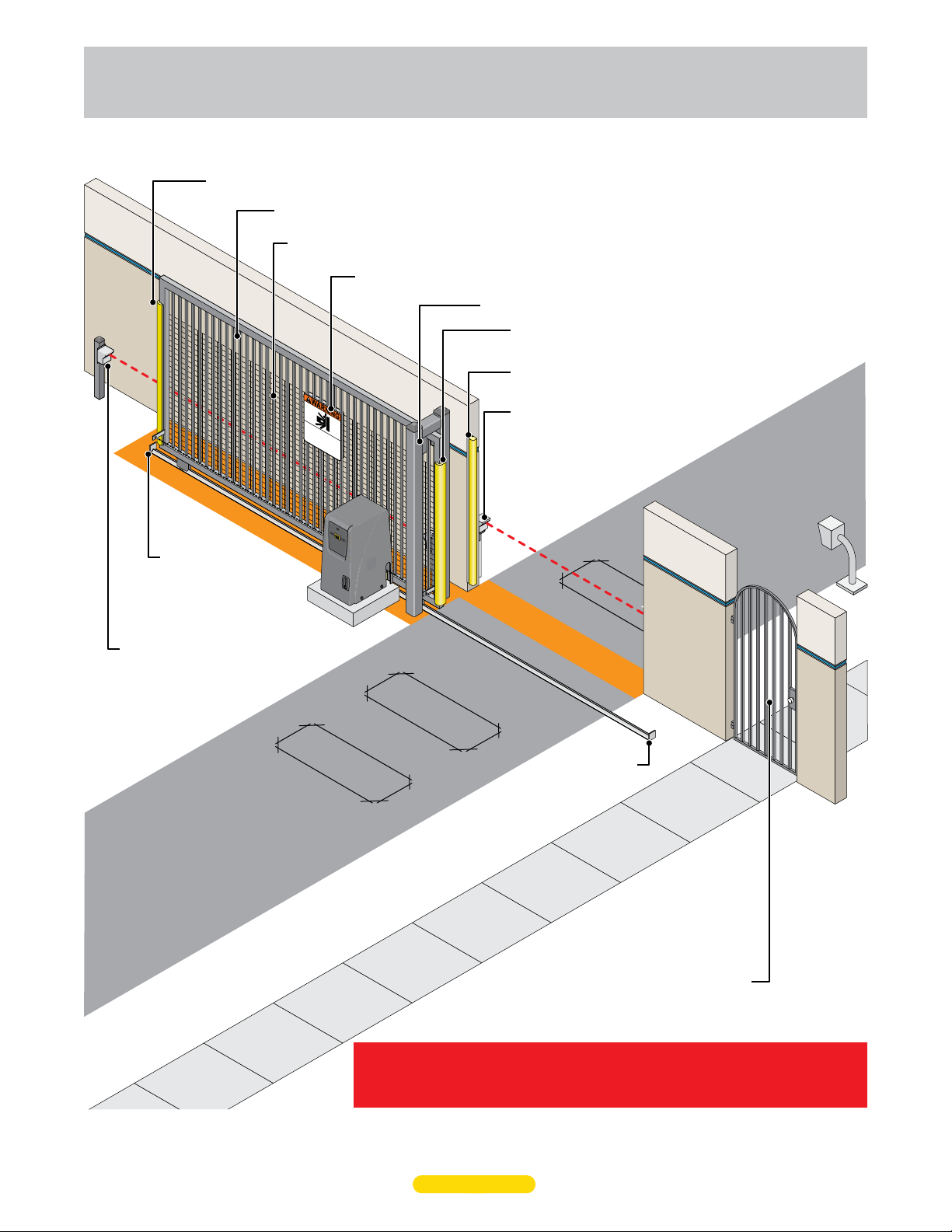
intended use of
slide gate operator
The operator is intended for use on a VEHICULAR slide gate ONLY. It is intended to be used WITH appropriate entrapment
protection safety devices and in-ground vehicle loop detection system. Pedestrians MUST use a separate entrance.
OPENING Direction Reverse Edge: Helps guard against the opening gate from entrapment.
Gate Pickets: The space between the gate pickets should be LESS than 2 1/4” or wire mesh should be installed.
Wire Mesh: 2” x 2” at least 6 ft high. Installed on gate when the space between the gate pickets is MORE than 2 1/4”.
Warning Signs: Should be installed on BOTH sides of gate area and easily visible.
Guide Rollers: Must be installed for safety.
CLOSING Direction Reverse Edge: Helps guard
against the closing gate from entrapment.
OPENING Direction Reverse Edge: Helps guard against the
opening gate from entrapment between wall and gate.
CLOSING Direction Photocell: Helps
guard against the closing gate from
entrapment.
Entrapment Area
Moving Gate Can
Serious Injury or Death
KEEP CLEAR! Gat
without
Do
prior
not let children operate the gat
in the gate area.
warning.
e may
This entrance is for veh
Pedestrians
must use separate entrance.
Cause
move at any time
e or
icles only.
play
Physical Stops:
Install on BOTH ends of
gate rail to limit the travel
of gate to the fully open
and fully closed positions.
OPENING Direction Photocell:
Helps guard against the opening
gate from entrapment between
wall and gate.
In-Ground Loops: Help
protect the gate operator
from accidentally opening
and/or closing on vehicles
in the gate’s path
Automatic Exit
Loop
Safety Loop
Entrapment Area
Safety Loop
Physical Stop
Pedestrians MUST use a separate entrance.
Gate operator IS NOT intended to be used on a PEDESTRIAN gate.
Entrapment sensors must be installed where entrapment or pinch point exist.
A minimum of TWO entrapment protection sensors MUST be installed, ONE in EACH
direction of gate travel or operator will NOT function.
UL 325 2018 Standard - MAX 1500 PRO/2200 PRO/F18 PRO Matrix III Instal
6
Safety - 5
l Version 7a
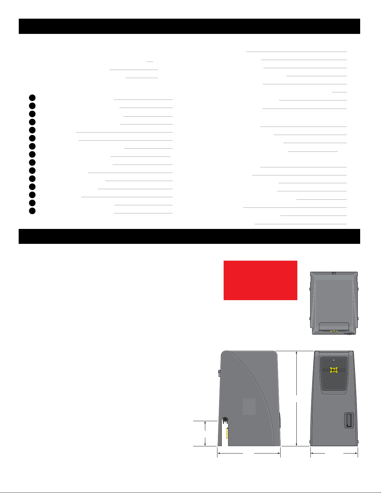
Table of Contents
Gate Safety
UL 325 Compliant Installation Requirements
UL 325 Model Classifications
Intended Use of Slide Gate Operator
Step-By-Step Installation
1A
Operator Placement (Standard)
1A
Connect Chain to Gate (Standard)
1B
Rear Mounting Position (Alternate)
1B
Connect Chain to Gate (Rear Pos)
2
AC Input Power
3
Ground Operator
4
Opening Direction/ID Plug/Operator
5
Entrapment Protection Wiring
6
Program Virtual Limit Sensors
7
Learn Gate Positions
8
Adjust ERD Reverse Sensor
9
Loops & Loop Detectors
10
Matrix III Settings
11
Wiring Opening Device Options
12
Learn Unlearned Sensor Inputs
Page
Safety-1-3
Safety-4
Safety-5
7-8
10
10
11
11
12
12
Additional Features
Programming
DIP-Switch Settings
Gate Shut-Off Switch
Electronic Gate OPEN / CLOSE
Gate Tamper Feature
Dropping the Chain - Gate Tamper is Armed (ON)
1
2
3
4
5
6
6
Dual Gate Operators Wiring
Gate Disable Feature
Troubleshooting
USB Black Box Port
Test Entrapment Sensors
Gate Cycling Troubleshooting
Matrix III LED Troubleshooting
Page
13
13
14
14
15
16
17
18
19
19
20
21-22
Commonly Used Safety Sensors
9
Omron E3K-R10K4
Omron IRB-RET
EMX IRB-MON Single Gate
EMX IRB-MON Dual Gates
Miller RBAND Monitored Wireless
Wiring Overview
Optional Magnet Limit Sensors
Optional Solar Power
23
23
24
25
26
27
28
29
specifications
UL 325 Class of Operation - MAX 1500 PRO/2200 PRO - Class I, II, III, IV.
MAX F18 PRO - Class III, IV ONLY.
Gate Type - Vehicular Slide Gate
Max Gate Length - 50 ft
Max Gate Weight:
• MAX 1500 PRO - 1500 lbs Level Gate
• MAX 2200 PRO - 2200 lbs Level Gate
• MAX F18 PRO - 1600 lbs Level Gate
Opening Time - Selectable speed control: (MAX 1500 PRO/2200 PRO - Up to 12 inch/sec)
(MAX F18 PRO - Up to 18 inch/sec)
Cycles per Hour AC Power - Continuous
Battery Back-Up Cycles (2- 7 Amp/Hr Batteries fully charged):
• Approximately 100 cycles
NOTE: The number of gate cycles using ONLY battery back-up power will vary
depending on the weight of the gate, the gate length, the operating condition
of the gate, temperature and the amount of charge the batteries have at the
beginning of the battery power only operation.
Input AC Power/Amps - Switchable: 115VAC / 6 Amp, 1 phase
or 230VAC / 2 Amp, 1 phase
Motor:
• MAX 1500 PRO - 1/2 HP 24VDC Brushless (6 million cycles)
• MAX 2200 PRO/F18 PRO - 1 HP 24VDC Brushless (6 million cycles)
Chain Size - #40
Operating Temperature: -4°F to 158°F (-20°C to 70°C)
Entrapment Protection:
- UL 325 Type A Inherent (ERD sensor)
- Inputs for NORMALLY CLOSED (N.C.) and 10K Type
UL 325 Type B1 (photocell)
and Type B2 (sensing edge)
7 1/2”
UL 325 2018 Standard - MAX 1500 PRO/2200 PRO/F18 PRO Matrix III Instal
7
TWO Entrapment protection
sensors MUST be installed,
ONE in EACH direction of
gate travel or operator will
NOT function.
29”
14 1/2”19”
l Version 7a
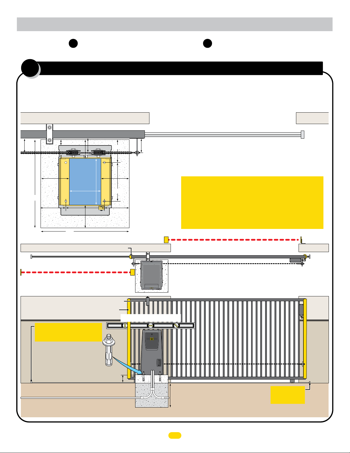
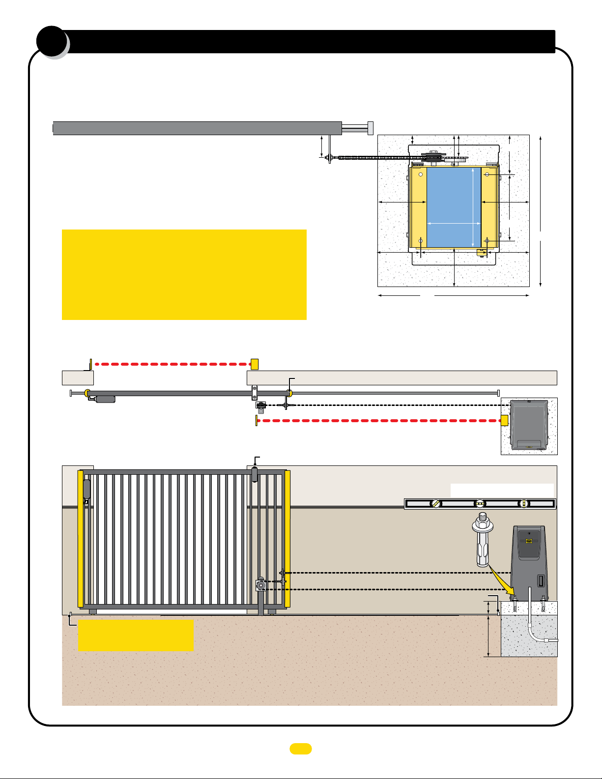
step-by-step installation
Choose either Front Mounting Position (Standard) or Rear Mounting Position (Alternate).
1A
Operator Placement (standard)
1A 1B
The gate must be properly installed and work freely in both directions prior to installation of the gate operator.
Operator in Front Position (Standard)
Guide Rollers
1.5”
4”5”
12.75”
Conduit
Area
24”
6.75”
Outside Property
OPENING Sensing Edge with Wireless Module
Inside Property
OPENING Photocell Beam
8.625”
10.5”
6.5”
24”
2” Gate Frame
Cover
Concrete Pad
6.2”
10.5”
6.75”
4”4”
7.5”7.5”
Operator
Position on
Concrete Pad
V-Rail
Conduit Guidelines and Suggestions
• REQUIRED - AC input power wire.
• REQUIRED - Entrapment protection OPENING and CLOSING photocell
and/or sensing edges.
• In-ground loop wires.
UL 325 2018 Standard
Safety sensors (Photocell or contact EDGE) must be
installed in BOTH opening and closing direction of gate
movement where entrapment or pinch point exist. TWO
safety sensor min. (N.C. or 10K type) MUST be installed or
operator will NOT function. All sensors must be UL325,
2018 compliant. See pages 7-8.
CLOSING Photocell Beam
Gate in Closed Position
See next page for chain information.
Operator in Front Position (Standard)
Wireless
Module
Physical Stop
Reflector
CLOSING
Sensing
Edge with
Wireless
Module
Guide rollers MUST be Installed to keep gate upright.
OPENING Sensing Edge with Wireless Module
Operator MUST be level.
IMPORTANT: Physical stops MUST
be installed on BOTH ends of rail to
keep gate from traveling off of rail.
Secure gate operator to
concrete pad with four
(4) 1/2” x 3” (min)
sleeve anchors.
6” above ground to avoid flooding.
Input Power
Concrete Depth Note: The heavier the gate, the deeper the concrete pad should be. At least two feet recommended for heavier gate.
1/2
Conduit Run
Concrete Pad
Check local building
codes in your area for
depth of concrete
before installation.
UL 325 2018 Standard - MAX 1500 PRO/2200 PRO/F18 PRO Matrix III Install Version 7a
1
MUST be installed
IMPORTANT:
Physical Stop
Module
Wireless
CLOSING
Sensing
Edge with
Wireless
Module
1A
YES
NO
YES
YES
NO
NO
NO
NO
NO
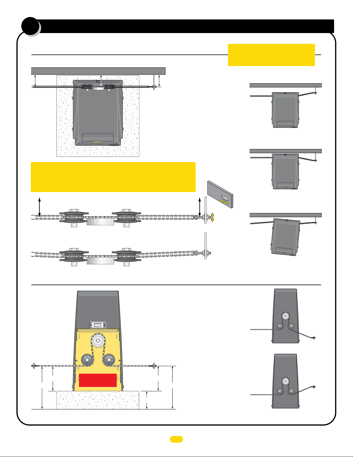
connect chain to gate (standard)
Top View of Operator
NOTE: 25 ft of #40 nickel plated chain included.
Minimum distance between the drive gear and gate is 4”.
4” Min4” Min
Drive
Gear
Chain
Bracket
YES
IMPORTANT: Operator and chain MUST be parallel to gate or the idler
wheels could fail. Use the “Fine Tune” adjustment on the gate bracket
connection bolt and make sure the chain runs through the idler wheels
without binding on the side chain guides.
YES
Side Chain Guide
Side Chain Guide
Idler Wheel
4” Min4” Min
NO
Gate Bracket
Fine Tune
Adjustment
IMPORTANT: Physical stops MUST be
installed on BOTH ends of gate rail to
keep gate from traveling off of rail.
NO
Operator is too far from gate.
Chain is NOT parallel to gate.
NO
Operator is too close to gate.
Chain is NOT parallel to gate.
NO
Operator is NOT parallel to gate.
Chain is NOT parallel to gate.
Back View of Operator
YES
Chain brackets MUST
remain same height as
idler wheels.
Chain
Bracket
Idler Wheels
Factory installed
position
Concrete Pad
Operator in Front Position (Standard)
Bracket
6”
Chain
7.5”7.5”
NOTE: The chain should
sag no more than one (1)
inch per 10 feet of travel.
Do not over tighten the
chain.
13.5”13.5”
2
NO
Chain
Bracket
DO NOT mount chain bracket too low on gate.
NO
Chain
Bracket
DO NOT mount chain
bracket too high on gate.
UL 325 2018 Standard - MAX 1500 PRO/2200 PRO/F18 PRO Matrix III Instal
l Version 7a
1B
rear mounting position (alternate)
The gate must be properly installed and work freely in both directions prior to the installation of the gate operator.
The chain is not visible when looking from outside of the property.
2” Gate Frame
Conduit Guidelines and Suggestions
• REQUIRED - AC input power wire.
• REQUIRED - Entrapment protection OPENING and CLOSING photocell and/or sensing edges.
• In-ground loop wires.
UL 325 2018 Standard
Safety sensors (Photocell or contact EDGE) must be
installed in BOTH opening and closing direction of gate
movement where entrapment or pinch point exist. TWO
safety sensor min. (N.C. or 10K type) MUST be installed or
operator will NOT function. All sensors must be UL325,
2018 compliant. See pages 7-8.
V-Rail
Physical Stop
4”
1.5”
4”5”
12.75”
6.2”
Conduit
7.5”7.5”
10.5”
24”
6.75”
Concrete Pad
6.75”
24”
8.625”
10.5”
Area
Cover
6.5”
Operator Position on Concrete Pad
Outside Property
CLOSING Sensing
Edge with Wireless
Module
Inside Property
CLOSING
Sensing
Edge with
Wireless
Module
CLOSING Photocell Beam
Wireless
Module
Gate in Closed Position
Wireless
Module
IMPORTANT: Physical stops MUST
be installed on BOTH ends of rail to
keep gate from traveling off of rail.
Operator in Rear Position
OPENING Sensing Edge with Wireless Module
OPENING Photocell Beam
Photcell to OPEN ONLY NC Input
Guide rollers MUST be Installed to keep gate upright.
OPENING Sensing Edge
with Wireless Module
Secure gate operator to
concrete pad with four
(4) 1/2” x 3” (min)
See next page for chain information.
6” above ground to avoid any flooding of the operator.
Illustrations not to scale
Operator MUST be level.
sleeve anchors.
Physical Stop
Check local building
codes in your area for
depth of concrete
before installation.
1/2
Conduit
Run
Input Power
Concrete Pad
Concrete Depth Note: The heavier the gate, the deeper the concrete
pad should be. At least two feet recommended for heavier gate.
UL 325 2018 Standard - MAX 1500 PRO/2200 PRO/F18 PRO Matrix III Instal
3
l Version 7a
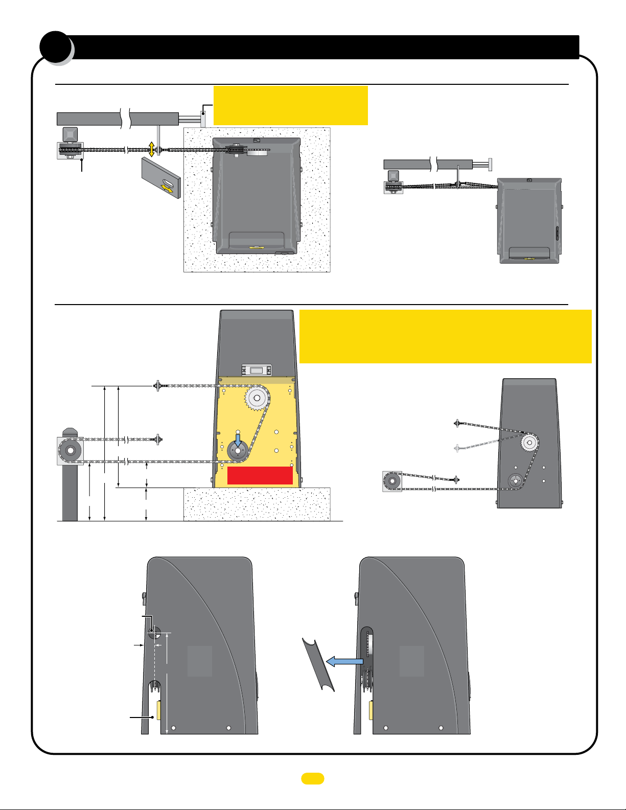
1B
YES
YES
NO
NO
connect chain to gate (rear pos)
Top View of Operator
NOTE: 25 ft of #40 nickel plated chain included.
Gate
Gate Bracket
Pulley Wheel
Safety Cover
Fine Tune
Adjustment
Operator and chains
MUST remain
parallel to gate.
Upper and lower
chain MUST align
with each other.
Operator in Rear Position
Back View of Operator
NOTE: The chain should sag
no more than one (1) inch per
10 feet of travel. Do not over
tighten the chain.
Upper chain bracket
MUST remain same
height as drive gear.
IMPORTANT: Physical stops MUST be
installed on BOTH ends of gate rail to
keep gate from traveling off of rail.
Drive
Gear
YES
IMPORTANT: Operator and chain MUST be parallel to gate or the idler
wheels could fail. Use the “Fine Tune” adjustment on the gate bracket
YES
connection bolt and make sure the chain runs through the idler wheels
without binding on the side chain guides.
Gate
Lower chain does NOT
align with upper chain.
NO
Pulley Wheel
(not supplied)
Same height as
idler wheel.
10.5”
22.5”
Lower chain Bracket
MUST remain same
height as pulley wheel.
16.5”
4.5”
6”
Drive
Gear
Move operator wheel
to lower hole position.
Concrete Pad
Idler
Wheel
Modify Cover for Rear Mounting Position
Drill 2” dia. hole for
upper chain exit.
Approx.1.5”
16.5”
Existing chain
exit slot.
Remove
DO NOT mount
chain brackets
too high or too
low on gate.
Chain
Bracket
Chain
Bracket
NO
Cut out cover
between new hole
and existing chain
exit slot.
Make sure cuts are
plumb with existing
chain exit slot.
UL 325 2018 Standard - MAX 1500 PRO/2200 PRO/F18 PRO Matrix III Instal
4
l Version 7a
W
ARNING
HIGH
VOLT
AG
E
ATTENTION!
HI
GH
VOLT
AG
E
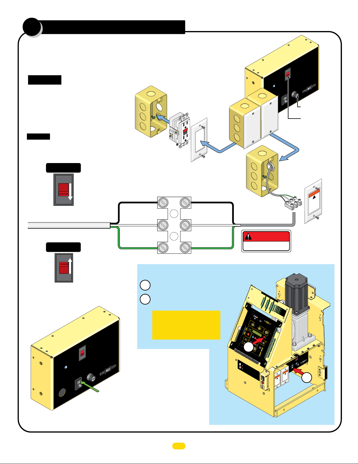
ac input power
WARNING
HIGH
VOLTAGE
2
Choose either 115V or 230V setting on input AC power selector switch.
Wire desired input AC power wire to power terminal. A additional single gang box is provided to
install power outlets if desired. GFCI outlet type is recommended.
CAUTION: Make sure circuit
breaker is OFF from incoming
AC input wire BEFORE wiring!
Additional single gang box
provided. Wire GFCI outlet
to the input AC wire
BEFORE connecting to
operator power terminal if
power outlets are desired.
Input AC Power Options
Additional
Power
Box
MAX
Toroid Box
AC
IN
On
Off
AC
Box
POWER
MAX Toroid 15 Amp
Select Input
Voltage
115V
115VAC or
230VAC
www.Max.US.com
FUSE
7 Amp
7 Amp Fuse
Input AC Power
Selector Switch
CAUTION: If input AC power selector
switch is set for 115V but input power
is actually 230 V, 7 Amp Fuse will blow.
Single Phase 115VAC Only
115VAC
Set to 115V
115 OR 230VAC
Power Wire
Single Phase 230VAC Only
115V
230VAC
Set to 230V
230V
Turn Power
ON
MAX
Toroid Box
AC
IN
LEDs should light up on operator.
Battery power automatically turns ON.
POWER
On
Off
Select Input
Voltage
115V
115VA C or
230VAC
FUSE
7 Amp
MAX Toroid 15 Amp
Turn Power ON
www.Max.US.com
Additional
Gang Box
GFCI Outlet
NOT provided
IMPORTANT: Make sure there are NO exposed bare
wires at the power terminal connection.
Line (Black)
Power Terminal
Neutral (White)
Chassis (Green)
Line (Black)
Neutral (White)
Chassis (Green)
Turn ALL Power OFF
Turn OFF AC POWER switch on MAX Toroid box.
1
Battery power will remain ON.
Press and HOLD Red ON/OFF BATTERY button
2
on the board until BEEP is heard, release button.
IMPORTANT: This procedure
must be followed whenever
ALL power must be turned
OFF on operator.
DO NOT
CYCLE
OPERATOR!
HIGH VOLTAGE!
BATT
E
RY
INP
UT
POW
ER /
SOL
AR IN
P
OWE
R
MOD
U
LE
P
ORT
MAX
MA
SENSE
NUAL
R
E
LEASE /
R
ES
E
T
O
1
A
FF
O
L
BD
AR
2
BLACK BOX
M
PORT
3
4
I
D
P
B
L
5
U
E
G
R
R
6
O
R
1
ID
2
PRO
PLU
3
G
G
4
R
AMMING
5
6
AMODE
7
8
DE
9
10
E
XIT P
MO
WR
O
FF
EXIT LOOP
GND
P
ROGR
AM
CENT
LOOP
ER
SOL
PWR
LOOP
A
SA
R MODE
FET
FA
Y
U
OFF
LTS
S
A
FET
Y
24VDC
ON
ON
OUTPU
GN
OPE
D
T
12VD
R
ATOR
C
OUTPU
PRIMARY
GN
D
T
SECONDARY
MI
NM
MA
XM
AL
N
IG
D
S
N
G
IO
D
IO
A
D
R
A
DEPT
EN
R
E
D
2
D
FIR
R
E
A
L
GN
I
NK
D
C
E
MAX OP
OK
/
EAS
IK
GN
D
P
A
D
REL
RIMARY/
STR
SE
L
GN
CO
EYP
D
NDARY
K
GN
LINK
D
MANUA
GN
D
+)
(
GN
-)
(
OPE
To
N
O
Turn OF
OFF
1
POWER
T
urn
B
OFF
atte
F
A
r
ALL PO
y
C
power w
P
OW
FF
O
N/
O
2
Pres
E
tery
t
Ba
R s
il
on t
l
r
wit
s and
em
ch
ain ON
he
HOLD
boar
d
R
un
ed
t
i
ON
l
BE
/
OFF BATTE
EP is heard
DANGER
EXIT CENTER SAFETY
B
A
TTERY
INPU
ERR
BATTE
T
OR
RY
E
VOL
B
A
TTERY
TAGE
1/2
IN U
S
E
F
BATT
BACKU
E
LE
BATTERY
RY
A
V
P M
OPE
E
TES
OD
N
R
EPLA
T
E
BATTE
C
OPE
E
R
1 TIME
N
Y
LEA
16
C
V
14
LO
E
MIN
S
ERD SENSITIVITY
E
12
D
1
3
ERD
9
MO
16
O
14
T
P
7
OVER
O
MIN
E
R
NING CLO
12
L
OAD
1
MAX
S
E
N
SE
3
ERD
9
MOTOR
7
OV
S
E
R
LOAD
ING
MAXIMUM CONTROLS
SWINGER / SLIDER
MI
NM
O
MOTION CONTROL
ON
/
OFF
OPEN
B
A
TTER
Y
J
S
OG
TO
QU
PCLOSE
I
CK
CLO
S
E
OFF
OP
E
N
LE
F
LE
T
FT
OPEN
G
GAT
A
RIGHT
E
R
I
GHT
G
ATE
MAGLOC
SP
EE
MAG
DEL
D
K
AY
LO
IN
CK
OF
C.
A
.
F
X
N
2.5 sec
OP
1.5 sec
R
E
N
ONLY
PHOTO C
NSO
CLO
E
SI
S
LS
N
OPEN
GOPENING
N
C
UL
/
C
LS N
UL
12VDC OUT
ENTRA
C
0K
P
1
R
GN
OPEN ONLY
O
D
C
ENS
LS
10
K
ONLY
LE
N
B
OP
10K
A
UL S
E
E
N
S
OP
/
S
I
C
T
O
LS
O
D
S
10K
L
N
12VDC
E
C
OM
T
ER
C
OUT
IN
P
GA
M
GN
PER
TA
OM
D
IGHT
M
C
FT
D
A
T
G R
GN
G LE
JO
O
D
J
GN
WE
on
R:
M
A
.
X
T
or
oi
d
box
.
R
,
Y
r
ele
button
a
s
e but
t
on.
MATRIX III
CLOSE
TIMER
FF
TE CLOS
N
C
AX
GATE O
C
OM
N
C
GN
N
O
P
E
N
C
OM
ED
D
MOTOR
INPUTS
MOTOR
POSITION
INPU
TS
SLIDE
R
LIMIT
SWIN
G
LIMIT
AC Power
Gang Box
EXIT
CENTER
SAFETY
TENTION!
AT
!
E
HIGH
TAG
L
ncher
VO
ra
nt
'b
a
e
ien
t
d
av
e
r
t
n
'e
l
Power
Terminal
AC
POWE
IN
On
Off
WARNING
!
HIGH
ect
e
nn
VOLTAGE
for
isco
it
d
ing un
power be
servic
WARNING
!
HIGH
ect
VOLTAGE
disconn
power before
servicing unit
Select Input
or
Voltage
AC
1
1
5V
m
115V
230VAC
www.Max.US.co
FUSE
R
mp
7 A
mp
A
Toroid 15
MAX
1
L
I
M
I
T
S
E
N
S
O
R
UL 325 2018 Standard - MAX 1500 PRO/2200 PRO/F18 PRO Matrix III Instal
l Version 7a
5
 Loading...