

Page 1
Page 2

- 1 -
CONTENTS
BEFORE USE ..................................................................................................................... 2
SAFETY INSTRUCTIONS ......................................................................................... 2
ACCESSORIES ......................................................................................................... 3
MAIN FEATURES ...................................................................................................... 4
PARTS DESCRIPTIONS ..................................................................................................... 5
HOW TO OPEN AND CLOSE FRONT COVER ................................................................. 5
DISPLAY AND KEYBOARD ............................................................................................... 5
DISPLAY LAYOUT..................................................................................................... 5
KEYBOARD LAYOUT ............................................................................................... 6
HOW TO OPERATE ............................................................................................................ 7
HOW TO SET UP ................................................................................................................ 8
SETTING OR CHANGING DATA .............................................................................. 8
BASIC OPERATION OF SETTING OR CHANGING DATA ..................................... 8
SETTING MODE 1 ............................................................................................................ 10
MACHINE MODE 1 (CODE 01) ............................................................................... 10
MACHINE MODE 2 (CODE 02)............................................................................... 10
PAY CLOSING DATE (CODE 03) ....................................................... ....... ............ . 11
60 OR 100 SCALE (CODE 04) ................................................................................ 11
DAILY TOTAL HOURS (CODE 05) ......................................................................... 12
SETTING MODE 2 (YEAR, MONTH, D ATE, HOUR, AND MINUTE) .............................. 14
SETTING MODE 3 ............................................................................................................ 14
HOLIDAY (CODE 01) ............................................................................................... 14
SPECIAL DAY (CODE 02) ...................................................................................... 15
LINE SHIFT TIME, IN/OUT AND OVERTIME WORKING (CODE 03 to 10, # FOR SPECIAL
DAY: CODE 11 to 17) .............................................................................................. 15
DAYLIGHT SAVING TIME (CODE 18 to 19) .................................................................. 16
SETTING OPTION ............................................................................................................ 18
CONNECTION TO EXTERNAL TIME SIGNAL .............................................................. 21
REPLACING INK RIBBON CASSETTE ........................................................................... 22
WALL MOUNTING AND LAID-DOWN POSITION INSTALLATION ............................... 23
ERROR CODES ................................................................................................................ 24
CAUTION CODE ............................................................................................................... 24
TROUBLE SHOOTING ..................................................................................................... 25
SPECIFICATIONS ............................................................................................................. 25
Page 3
- 2 -
BEFORE USE
SAFETY INSTRUCTIONS
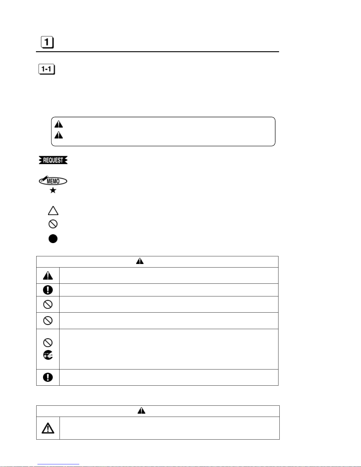
■INDICATIONS
This instruction manual and the product use various indications to help you use this instrument safely and properly.
The following describes those ind i cations.
WARNING:
Negligence could lead to serious injury or death.
CAUTION:
Negligence could lead to an injury, damage of your property, or
cause loss of created data.
Describes operations that may cause damage to the instrument and require a repair, or operations that require resetting the machine, etc., to restore the condition
of the instrument.
Describes the points of operation and tips.
Describes a functional precaution.
■SYMBOLS
Denotes “What you should be aware of.”
Denotes “What you must not do.” An indication in or near this symbol shows a
specific prohibition.
Denotes “What you must do.” An indication in this symbol shows a specific in-
struction.
WARNING
This is a class A product. In a domestic environment this product may cause radio interference in which cas e th e user may be required to take adequate measur e s .
Clean a power cord plug regularly. Dust on the plug could cause a fire.
Obtain power directly from a single plug socket. Avoid connecting many wires to one
plug socket. It could lead to a fire.
Do not connect/disconnect a po wer plug with a wet hand. It could cause an elect ric
shock.
● Do not operate the instrument, if it is out of order. If it is operated in an out-of-order
state, such as it is smoking, emitting an abnormal sound, or smelling funny, it could
cause a fire or electric shock. Disconnect a power plug immediately from a socket
and contact your dealer/distributor for a repair.
● Disconnect a power plug before connecting to an external time signal.
A lithium battery is used inside for memory backup. Never replace the lithium battery
by yourself. Contact your dealer/distributor for replacement.
CAUTION
Data stored in the internal memory cannot be stored permanently. We will not be responsible for damages and lost profits caused by loss of data attributed to battery consumption, trouble, repair, and so on.
Page 4
- 3 -
Never disassemble or modify this instrument. It could cause a fire, electric shock, or
other problems.
● Do not inse rt foreign substances such as finge rs, pens, wire, or paper into this instrument. It could damage the ins trument or cause a fire.
● Use correct supply voltage. Other voltage level could damage the instrument.
● Do not splash water or chemicals on the instrument. If water gets inside the in-
strument, disconnect a power plug immediately from a plug socket and contact your
dealer/distributor for a repair. It could damage the instrument or cause a fire or
electric shock.
● Do no t pu t paper or cloth on the inst rument. It could cause a fire.
● Do not place any heavy material on a power cord. It could cause damage or a fire.
● Never touch a printer head. It is very hot just after printing and you could get
burned. Also, dirt on your hand could cause trouble to the printer head.
● When th e in stru me nt is not g oing to b e ope rated f o r a lo ng period o f ti me, b e sure to
disconnect a power cord from a power socket for your safety.
● When disconnecting a power cord, be sure to hold a power plug. Do not pull on the
power cord, or the cord could be broken and cause a fire or ele c tr ic shock.
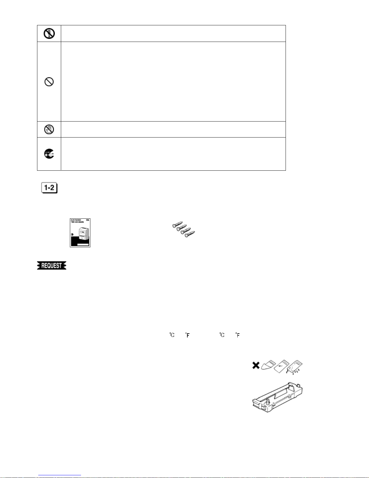
ACCESSORIES
This instrument comes with the following accessories. Confirm that they are included before using the machine.
1. Instruction manual
2. Screws for wall mounting
INSTRUCTION MANUAL
☆Beforeusing thisinstrument, study thismanual toensure
safetywarningand instructions.Keep thisinstruction manual
with the instrument for futurer eference.
2700
: 1 booklet
: 4-pcs.
◆ Do not drop or hit the instrument.
◆ Install this instrument away from the following places:
1. Any place that is not level or that is subject to vibration.
2. Any place that has dust or high humidity. Keep beverages and liquid
containers away from this instrument.
3. Any place that the temperature goes below 0 /32 or over 40 /104 .
4. Any place that catches direct sunlight or is located close to a heat source.
◆ Do not inse rt cards or paper other than the specified time ca rds for this instrument. Do not use time cards that are bent or torn.
◆ Be sure to use a dry cloth for cleaning. Do not use solvents (alcohol, benzene, thinner, etc.) or a damp cloth.
◆ Do not re-ink cartridge. Replace with ink ribbon cassetteER-IR102E.
◆ Do not hang this instrument on a wall using anything other than the included plate for wall mount i ng.
◆ The socket-out le t shall be installed near the equipment and shall be easily accessible.
◆ A 30-minute break is required after continuous printing 15 minutes.
Page 5
- 4 -
MAIN FEATURES
1. Up to 6 columns (Up to 4 columns when using the Daily Total Hours function).
2. Two-color printing (Black/Red).
3. Printing Daily Total Hours calculation and Accumulation of Daily Total Hours.
4. Can select regular working tim e or ov er time as Daily Total Hours.
5. Setting up to 22 times for external time signal.
6. Setting another program for Special day.
7. Printing regular minutes (1/60) or 1/100
th
of an hour.
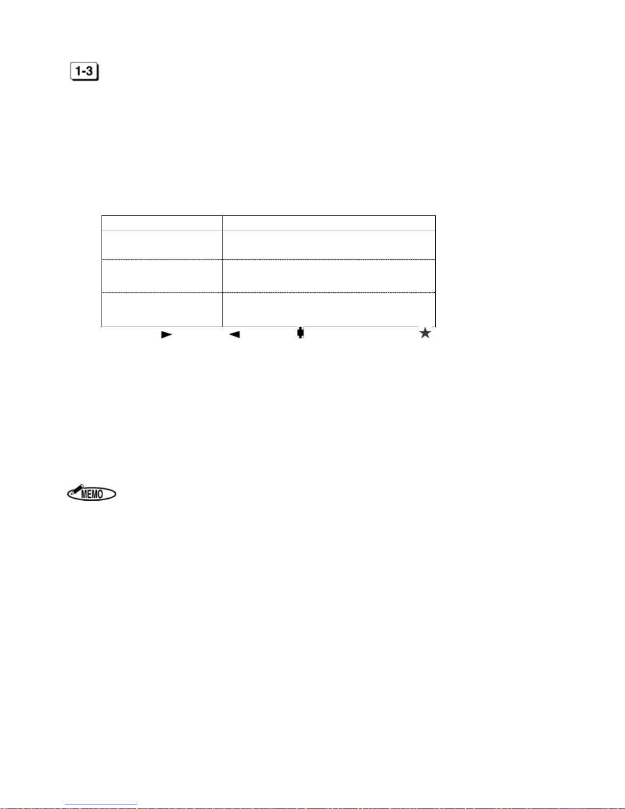
8. Can select one of three styles from the following table.
Capacity of employees Setting program
150 employees
Using Next D ay Ove rtime function
(Without Daily Total Hours function)
130 employees
Using Daily Total Hours function
(Without Next Day Overtime function)
60 employees
Using Daily Total Hours function and Next
Day Overtime function
9. Printing “Late-in: ,” “Early-out: ,” “Overtim e : ” and “Next Da y Overtime: ” symbols.
10. Can select fully automatic or manual operation.
11. Password protection for settings.
12. Three kinds of installation (Table Top, Wall Mounting, and Laid Down Position).
13. Three kinds of pay period formatting (Mo nthly, Weekly or Bi-w e ekl y).
14. Daylight Saving Time (for summer time).
15. Printing past midnight in the same line of the day by Line Shift Time.
16. Built-in lit hi u m battery protects the cl ock, calendar and program data for 3 years.
17. Twelve / twenty-four hour display formats.
18. Time / Date / Month / Year are already preset.
Some areas or countries will be required to reset the time.
Page 6
- 5 -
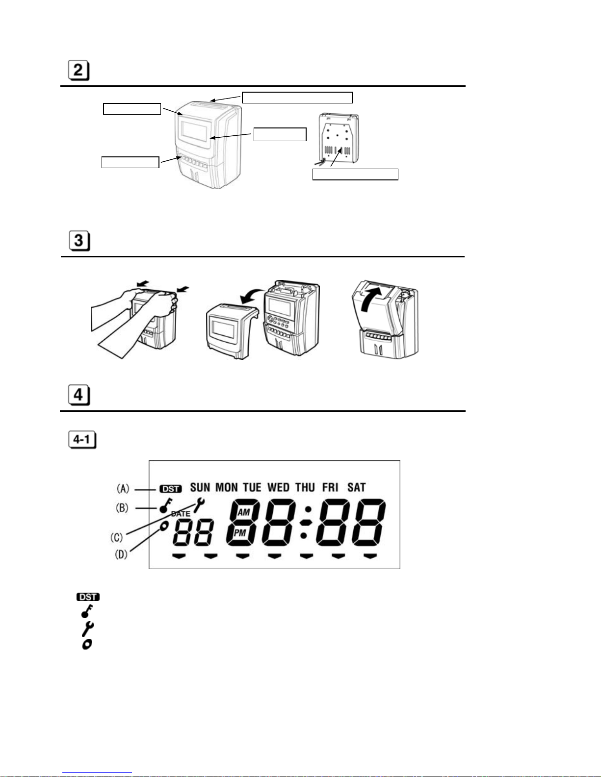
PARTS DESCRIPTIONS
HOW TO OPEN AND CLOSE FRONT COVER
DISPLAY AND KEYBOARD
DISPLAY LAYOUT
(A) symbol appears Daylight Saving Time activates.
(B) symbol appears Daylight Saving Time activates.
(C) symbol appears during settings are protected by password.
(D) symbol appears while you set IN/OUT program for Special day.
Pull as illustrated above. Remove a front cover. Push as illustrated above.
Time card insertion slot
Display
External key
Wall mounting plate
Front cover
Page 7
- 6 -
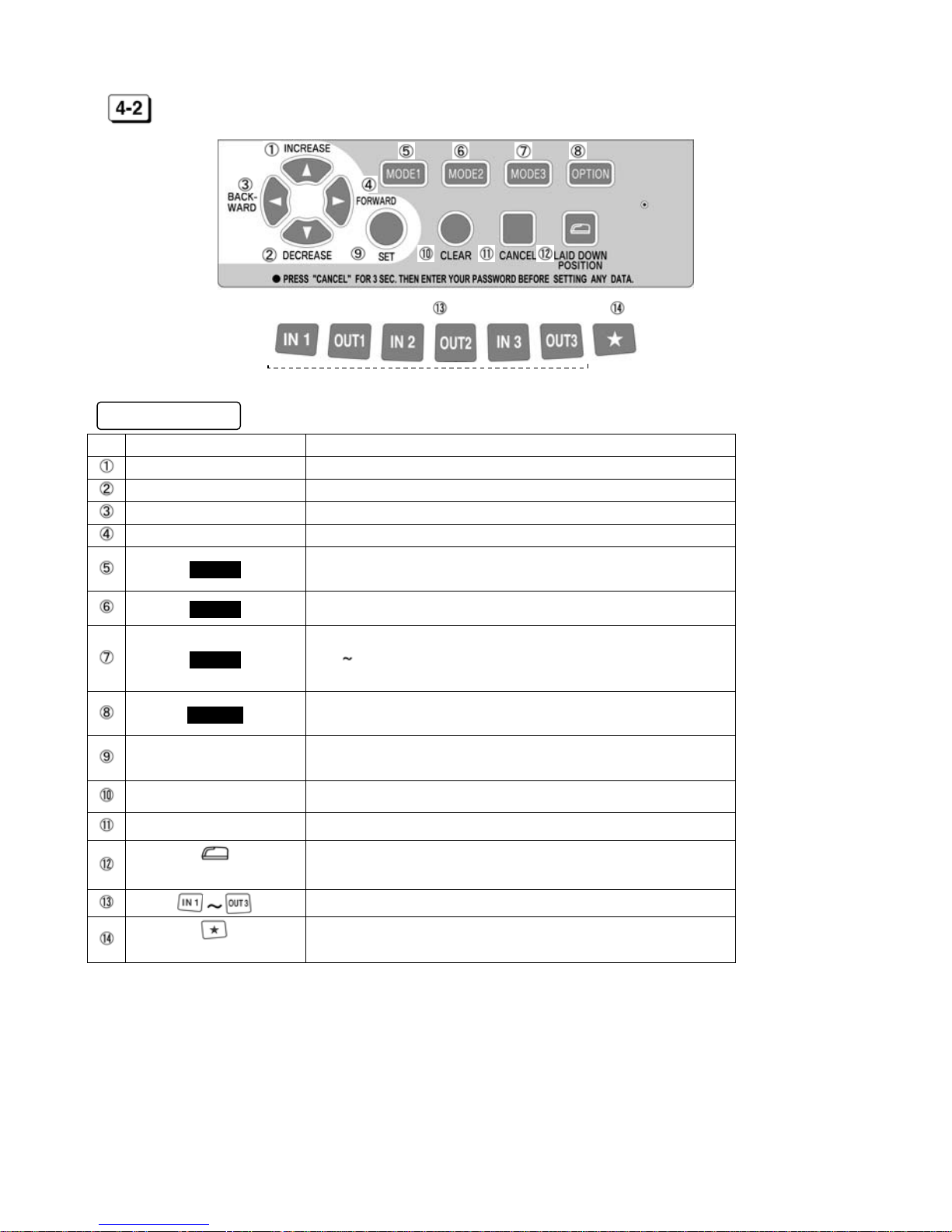
KEYBOARD LAYOUT
Functions of keys
No. Description Functions
INCREASE To increase num ber.
DECREASE To decrease number.
BACKWARD To back setting item (Code No.).
FORWARD To forward setting item (Co de No .).
MODE1
To set Machine Mode1, Machine Mode2, Pa y Closing Date, 60
or 100 scale and Daily Total H ours. (See [7] on page 10 )
MODE2 To set Year, Month, Date and current Time. (See [8] on page 14)
MODE3
To set Holiday, Special Day, Line Shift Time, Working Time
(IN1 OUT3, OST) and Daylight Saving Time.
(See [9] on page 14)
OPTION
To set Password, Time Length, Time Signal and LCD Backlig ht.
(See [10] on page 18)
SET
To register all setting data and return to the start of setting
mode.
CLEAR To initialize current setting item.
CANCEL To return to the start of setting mode without registration.
(LAID DOWN POSITION KEY)
To turn the time on the display upside down.
To select a desire d column.
To print the time in the same line of the day after Line Shift Time.
(NEXT DAY OVERTIME KEY)
[External Keys]
Page 8

- 7 -
HOW TO OPERATE
CAUTION
Install this instrument on a level place.
Do not install on or near a place subject to vibration.
1. AUTOMATIC OPERATION
Column to be printed is sh ifted automatically in the orde r of IN1, OUT1, IN2, OUT2, IN3 and OUT3 without
pressing any external keys.
1. Insert time card to the position where automatic feed starts.
2. Time card will be ejected automatically after printing the time.
2. MANUAL OPERATION
ER-2700 allows manual operation to select a desired column to be printed on.
1. Select a desired column to print by pressing
“IN1,” “OUT1,” “IN2,”
“OUT2,” “IN3”
or
“OUT3”
key.
2. symbol appears at the selected column on the display.
3. Insert time card to the position where au tomatic feed starts .
4. Time card will be ejected automatically after printing the time.
1. Do not keep holding the time card during printing.
2. Do not pull or push time card with your hand.
3. Do not cover any of small holes at both edges on time card.
1. If “E-01” appears on the display, the time card has been inserted
incorrectly. (See [14] on page 24)
2. When using Daily Total Hours function, ER-2700 automatically prints
Daily Total Hours in the 5
th
column and Accumulation of Daily Total
Hours in the 6
th
column after printing the time in the 4th column.
Page 9
- 8 -
HOW TO SET UP
SETTING OR CHANGING DATA
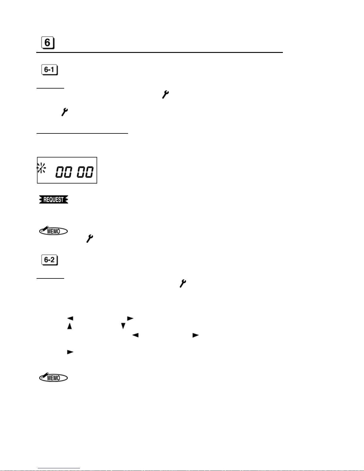
Operation
1. Press “CANCEL” key for 3 sec. or more. The symbol appears on the display.
2. After all changed data in each mode are registered, press the “CANCEL” key again.
The symbol disappears.
Password protection for settings
Password is able to set up to protect settings. The password is required for settings or changing data after it has
been set up in setting OPTI ON. (See [10 ] on page 18)
Making note of the “Password” and keep it in a safe
place to prevent it from being lost or used by an unauthorized person.
If you do not touch any keys for 60 seconds,
the symbol disappears automatically.
BASIC OPERATION OF S ETTING OR CHANGING DATA
Operation
1. Press the “CANCEL” key for 3sec. or more. The symbol appears on the display to indicate the setting
mode is on. If password has been set up, enter the password before into the setting mode.
2. Press “MODE 1,” “MODE 2,” “MODE 3” or “OPTION” key to select setting mode.
Then first setting item (CODE 01) is displayed.
3. Press “
(BACKWARD)” or “ (FORWARD)” key to select setting item.
4. Press “
(INCREASE)” or “ (DECREASE)” key to change data. (The changeable data blinks.)
5. If the changed data is OK, press “
(BACKWARD)” or “ (FORWARD)” key to move to next setting item.
6. Press “SET” key to register all changed data and to return the start of setting mode. Alternatively, you can
press “
(FORWARD)” key in last setting item to register all changed data and to return to the start of set-
ting mode.
By pressing “CANCEL” key during setting, you can return to the start of setting
mode without registration.
Page 10

- 9 -
The Contents of Setting Item
[Machine Mode1]
[Year]
[Holiday] [Password]
[Machine Mode2] [Month, Date] [Special Day] [Time Length]
[Pay Closing Date] [Hour, Minute] [LST]
[Time Signal 1]
[60 or 100 scale] [IN1]
[Daily Total Hours] [Time Signal 22]
[OUT3]
[OST]
[LCD Display]
[IN1 for Special Day]
[OST for Special Day]
[Starting Date of Day Light Saving Time]
[Ending Date of Day Light Saving Time]
◆ After pressing “SET” key, all changed data in each mode are registered and the display re-
turns to the start of setting mode ( symbol appears on the display.).
◆ Alternatively, you can press “
(FORWARD)” key in last setting item to register all changed
data, and then the displa y returns to the start of setting mode.
1. When selecting "3(Without Daily Total Hours function)" in Machine Mode 1
setting (CODE 01 in MODE 1), Daily Total Hours setting (CODE 05 in MODE1)
is not displayed.
2. When setting no Special Day in Special Da y setting (CODE 02 in MODE 3),
“CODE 11” to “CODE 17” are not dis pl ayed.
Code No.
Setting data
Page 11

- 10 -
SETTING MODE 1
Press “MODE 1” key after pressing the “CANCEL” key for 3sec. or more.
If password has been set up, enter the password before into the setting mode.
MACHINE MODE 1 (CODE 01)
Press or to select a desired number from the following table and set “Capacity of Employees.”
According to the number, each function will be activated.
◆ Initial data=1
Number
Capacity of
Employees
Function Printed result on Time Card
Daily Total Hours Next Day Overtime 5th column 6th column
1 60 Use Use
Daily Total
Hours
Accumulation of
Daily Total Hours
2 130 Use Not use
Daily Total
Hours
Accumulation of
Daily Total Hours
3 150 Not use Use Time
Time
1. When selecting “1,” you cannot use “IN3” and “OUT3” external keys.
When pressing these keys, “E-90” appears on the display.
2. When selecting “2,” you cannot use “IN3,” “OUT3” and “Next Day Over-
time( )” keys. When pressing these keys, “E-90” appears on the display.
MACHINE MODE 2 (CODE 02)
Press or to select a desired number from the following table and set “12/24-Hour Format”
and “Pay Period.”
◆ Initial data=1
Number 12/24-Hour Format Pay Period
1
12H
Monthly
2
24H
3
12H
Weekly
4
24H
5
12H
Bi-weekly
6
24H
1. The time is printed only in 24-hour format.
2. When setting in the “Laid Down Position,” only 24-hour format is displayed.
Page 12

- 11 -
PAY CLOSING DATE (CODE 03)
After setting “Machine Mode2, ” “Pay Closing Date” is shown on the display.
Monthly
Press or key to select “Pay Closing Date.” When the display shows a desired closing date, press “ ”
key.
From
to
Weekly
Press or key to select “Pay Closing Date”(from today to the next 6 days).
When the display shows a desired closing date, press “
” key.
From
to
Bi-weekly
Press or key to select “Pay Closing Date”(from today to the next 13 days).
When the display shows a desired closing date, press “
” key.
From
to
60 OR 100 SCALE (CODE 04)
Press or to select a desired number from the following table and set “Time Printing Style.”
◆ Initial data=1
Number Time printed on IN/OUT columns Daily Total Hours
Accumulation of Daily
Total Hours
1
Regular minutes (1/60) Regular minutes (1/60) Regular minutes (1/60)
2
1/100
th
of an hour 1/100th of an hour 1/100th of an hour
3
Regular minutes (1/60) 1/100
th
of an hour 1/100th of an hour
In Europe, set Date first and Month second.
1. When using 1/100
th
of an hour as “Time Printing Style”, ER-2700 prints the ad-
justed time as shown on the “Equivalent Time Chart.” And Accumula tion of
Daily Total Hours is adjusted after calculating in Regular minutes (1/60).
(See page 14)
Page 13

- 12 -
Equivalent Time Chart
Regular minutes
(1/60)
1/100th of an hour
(1/100)
Regular minutes
(1/60)
1/100th of an hour
(1/100)
Regular minutes
(1/60)
1/100th of an hour
(1/100)
00 0.00 20 0.34 40 0.66
01 0.02 21 0.35 41 0.68
02 0.04 22 0.36 42 0.70
03 0.05 23 0.38 43 0.72
04 0.06 24 0.40 44 0.74
05 0.08 25 0.42 45 0.75
06 0.10 26 0.44 46 0.76
07 0.12 27 0.45 47 0.78
08 0.14 28 0.46 48 0.80
09 0.15 29 0.48 49 0.82
10 0.16 30 0.50 50 0.84
11 0.18 31 0.52 51 0.85
12 0.20 32 0.54 52 0.86
13 0.22 33 0.55 53 0.88
14 0.24 34 0.56 54 0.90
15 0.25 35 0.58 55 0.92
16 0.26 36 0.60 56 0.94
17 0.28 37 0.62 57 0.95
18 0.30 38 0.64 58 0.96
19 0.32 39 0.65 59 0.98
DAILY TOTAL HOURS (CODE 05)
Press or to select a desired number from the following table and set “Style of Daily Total Hours.”
ER-2700 prints Daily Total Hours in the 5
th
column and Accumulation of Daily Tota l Hours in the 6th column automat-
ically while printing in the 4
th
column.
◆ Initial data=1
Number Style of Daily Total Hours
1 Regular work time
2
Overtime
1. If “2(Overti me work)” is set but Starting time of Overtime Work is not set in
“MODE 3,” ER-2700 prints “0:00” or”0.00” in the 5
th
column.
2. If “3(No use the Daily Total Hours function)” is selected in “Machine Mode1
(CODE 01)”, this setting item (CODE 05) does not appear.
Page 14

- 13 -
Printing Examples of Daily Total Hours
1. Setting data: CODE 01=1 (Using Daily Total Hours function)
CODE 04=1 (
Regular minutes (1/60))
D
1
1
9:01111:59112:59116:40 6:39 6:39
2
2
8:58212:01213:10218:27 8:20 14:59
IN3 OUT3IN1 OUT1 IN2 OUT2
2. Setting data: CODE 01=1 (Using Daily Total Hours function)
CODE 04=3 (
1/100th of an hour)
D
1
1
9:01111:59112:59116:40 6.65 6.65
2
2
8:58212:01213:10218:27 8.34 14.98
IN3 OUT3IN1 OUT1 IN2 OUT2
#1: In case of 1/100
th
of an hour, Accumulation of Daily Total Hours is changed from Regular
minutes (14:59) to 1/100
th
of an hour (14.98). The accumulated hours are not same as the
hours added 6.65 to 8.34.
3. Setting data: CODE 01=3 (Not using the Daily Total Hours function)
CODE 04=1 (
Regular minutes (1/60))
D
1
1
9:01111:59112:59116:40 6.65 6.65
2
2
8:58212:01213:10218:27 8.34 14.98
IN3 OUT3IN1 OUT1 IN2 OUT2
1. When time is not printed in the 4th column, ER-2700 does not print the Daily Total Hours and Accumulation of Daily Total Hours. If you cannot print the time in
the 4
th
column by using automatic operation, use manual operation by pressing
“OUT2.”
2. When IN and OUT have not bee n printed in pairs, ER-2700 cann ot output Dail y
Total Hours and A c cumulation of Daily Total Hours.
[Daily Total Hours] [Accumulation of
Daily Total Hours]
[Daily Total Hours] [Accumulation of
Daily Total Hours]
#1
Page 15

- 14 -
SETTING MODE 2 (YEAR, MONTH, DATE, HOUR, AND
MINUTE)
Press “MODE 2” key after pressing the “CANCEL” key for 3sec. or more.
If password has been set up, enter the password before into the setting mode.
[Example] 1:35 (PM), 21st May, 2013
Procedure [MODE 2] Display
Press “MODE2” key.
Current Year is shown on the display.
Press to display the Month/Date.
Press
to blink the Date.
Press or until the display shows “21.”
Press to display the Hour/Minute.
Press
to blink the Minute.
Press or until the display shows “35.”
Press the “SET” key to register the changed data.
The display returns to the start of setting mode.
1. symbol appears during Daylight Saving Time activates.
2. In Europe, set Date first and Month second.
3. Clock starts at “00” seconds when the “SET” key is pressed.
SETTING MODE 3
Press “MODE 3” key after pressing the “CANCEL” key for 3sec. or more.
If password has been set up, enter the password before into the setting mode.
HOLIDAY (CODE 01)
Set a day of the week as “Holiday.” Press the following keys to light on/off the day of the week.
The days of weeks that are lit up mean “Holiday.”
◆ Initial data=Nothing (All days are lit off.)
Key
Day of
the week
SUN MON TUE WED THU FRI SAT
ALL days are
lit on.
ALL days are
lit off.
1. Times on Holidays are printed in red color without any symbols.
2. Daily Total Hours on Holiday does not correspond to IN/OUT program in MODE 3.
Page 16

- 15 -
SPECIAL DAY (CODE 02)
Set a day of the week as “Special day.” Press the following keys to light on/off the day of the week. The days of
the week that are lit up mean “Special day.”
◆ Initial data=Nothing (All days are lit off.)
Key
Day of
the week
SUN MON TUE WED THU FRI SAT
ALL days are
lit on.
ALL days are
lit off.
1. You can set IN/OUT program for Special day in CODE 11 to CODE 17.
2. Special day and Holiday cannot be set to the same day of the week.
“E-91” appears on the display.
LINE SHIFT TIME, IN/OUT AND OVERTIME WORKING
(CODE 03 to 10, # FOR SPECIAL DAY: CODE 11 to 17)
Set LST, IN/OUT and OVERTIME program to activate printing function of symbols, “Late-in: ,” “Early-out: ,”
“Overtime:
.”
Daily Total Hours is calculated according to this program.
CODE No. Contents of setting program Initial data
LST (Line Shift Time=Day change time) 3 : 00
IN1 (Working start time) - - : - -
OUT1 (Working end time) - - : - -
IN2 (Working start time) - - : - -
OUT2 (Working end time) - - : - -
IN3 (Working start time) - - : - -
OUT3 (Working end time) - - : - -
OST (Starting time of Overtime work) - - : - -
IN1 for Special Day (Working start time) - - : - -
OUT1 for Special Day (Working end time) - - : - -
IN2 for Special Day (Working start time) - - : - -
OUT2 for Special Day (Working end time) - - : - -
IN3 for Special Day (Working start time) - - : - -
OUT3 for Special Day (Working end time) - - : - -
OST for Special Day (Starting time of Overtime work) - - : - -
1. The time is di splayed in only 24-ho ur format.
2. The CODE 11 to 17 are displayed only when Special day is set in CODE 02.
3. During setting the CODE 11 to 17 for Special day,
symbol appears on the d is-
play.
4. Times with ”Late-in” and “Early-out” symbols are printed in red color.
Page 17

- 16 -
Example Line Shift Time (Day change time) : 4 : 00
Starting time of work : 9 : 00
Starting time of lunc h : 12 : 00
Ending time of lunch : 13 : 00
Ending time of work : 17 : 00
Starting time of Overtime work : 17 : 30
Special day : Nothing
Procedure Display
Press to display CODE 03.
Current Line Shift Time is shown on the display.
Press or until the display shows “4:00.”
Press to display CODE 04 (IN1).
Press
or until the display shows “9.”
Press until the display shows CODE 05 (OUT1).
Press
or until the display shows “12.”
Press until the display shows CODE 06 (IN2).
Press
or until the display shows “13.”
Press until the display shows CODE 07 (OUT2).
Press
or until the display shows “17.”
Press until the display shows CODE 10 (OST).
Press or until the display shows “17.”
Press
to move the cursor to Minute.
Press or until the display shows “30.”
Press
to display CODE 18.
DAYLIGHT SAVING TIME (CODE 18 to 19)
Set “Starting and Ending Date of Daylight Savi ng Time” after setting “OST .” In case of setting no Special day
in CODE 02, CODE 18 is displayed following CODE 10.
When setting the last week of the mo nth, set “L” for the last week even if the last
week is the 4
th
week.
(
Position for the month) (Position for the week
)
Page 18

- 17 -
Example
Starting Date of Daylight Saving Time : Sunday of the last week in March.
Ending Date of Daylight Saving Time : Sunday of the last week in October.
Procedure Display
Press to display CODE 18.
St ar ti n g Date of Daylight Saving Time is shown on the display.
Press or until the display shows “3” for March.
Press to move the cursor to set the week.
Press
or until the display shows “L” for the Last week.
Press to move the cursor to set .the day of the week.
Move the cursor to the position of “SUN” for the day of the week by
pressing
or .
Press to display CODE 19.
Press
or until the display shows “10” for October.
Press to move the cursor to set the week.
Press
or until the display shows “L” for the Last week.
Press to move the cursor to set .the day of the week.
Move the cursor to the position of “SUN” for the day of the week
by pressing
or .
Press
or “SET” key to register the changed data, and then the
display returns to the start of setting mode automatically.
1. During the period of Daylight Saving Time, symbol appears on the display.
2. Once set, Daylight S aving Time will be adjusted aut omatically from the following
year, in accordance with the setting data.
Page 19

- 18 -
SETTING OPTION
Press “OPTION” key after pressing the “CANCE L” ke y for 3sec. or more.
If password has been set up, enter the password before into the setting mode.
PASSWORD (CODE 01)
A 4-digit password can be set to prevent someone other than the administrator from modifying the time or
changing the settings.
1. Press
or to change the number of each digit.
2. Press
to set each digit and to move to the next digit. When is pressed at the 4
th
digit, password set-
ting is completed and move to the CONNECTING TIME LENGETH (CODE 2) as the next setting item.
[1
s
t
digit]
[2
n
d
digit]
[3
r
d
digit]
[4th digit]
After password setting is completed, the symbol is always displayed while waitin g. Before entering the
setting mode, the password input screen is displayed; you cannot enter the setting mode unless a correct
password is input.
To set no password, p ress the “CLEAR” key in the passwo rd setting screen to display “– – – –,” followe d
by the “SET” key. If “– – – –“ (initial value) is displayed, press the “SET” key .
[Initial value]
Making note of the “Password” and keep it in a safe
place to prevent it from being lost or used by an unauthorized person.
Page 20

- 19 -
CONNECTING TIME LENGTH (CODE 02)
Set “CONNECTING TIME LENGTH” for external output. ER-2700 can control connecting time length to external
bell, buzzer or chime.
Press
or to select the desired connecting time length up to 60sec.
◆ Initial data= 10 sec.
Example
Connecting Time Length=15 seconds
Procedure Display
Press or until the display shows “15.”
Press to display CODE 03 as the next setting item.
EXTERNAL TIME SIGNAL (CODE 03 to 24)
Set the time and the day of the w ee k to connect to external bell , buzzer or chime.
After setting the time, select the day of the week.
ER-2700 can set “External Time Signal” up to 22 times.
◆ Initial data: Time=- - : - - The day of the week=All days
Key
Day of
the week
SUN MON TUE WED THU FRI SAT
ALL days are
lit on.
ALL days are
lit off.
Example
Time=AM9:00, The day of the week=Mon, Tue, Wed, Thu, Fri
Procedure Display
Press or until the display shows “9.”
Press to move the cursor to set the minute.
Press or until the display shows “00.”
Press to move the cursor to set the day of the week.
Press and key to light off “SUN” and “SAT.”
Press to display CODE 03 to set the next time and the day of
the week of Time Signal.
1. ER-2700 can contro l connecting time length to external bell from 1 to 60 seconds
by 1second.
(Connecting Time Length to the External Bell)
Page 21

- 20 -
LCD BACKLIGHT (CODE 25)
“LCD Backlight” is shown on the display after setting “EXTERNAL TIME SINGNAL.”
Select the Backlight mode for your style.
Press
or to select the desired number from the following table.
Number LCD Backlight
1
ON
2 OFF
3
Illuminated only when operation
Page 22

- 21 -
CONNECTION TO EXTERNAL TIME SIGNAL
WARNING
Disconnect a power plug bef ore connecting to an external time signal.
ER-2700 has a relay contact output.
An external bell, buzzer or chime, which are operated in the following methods, is useable.
(Contact capacity: 5A 30V DC)
Procedure
1. Disconnect a power plug. Remove screw and an
attached wall mounting plate as illustrated.
2. Connect a wire to a terminal block using a screwdriver
as illustrated.
In case of connection is made to a chime, etc. using
ER-2700 as a contact.
3. Take out wires through the take out port as illustrated
and attach the wall mounting plate to body.
External
time signal
Page 23

- 22 -
REPLACING INK RIBBON CASSETTE
Use only ER-IR102E ink ribbon cassette.
Replace an ink ribbon cassette as below, if the printing is too light.
CAUTION
Never touch a printer head. It is very hot just after printing and you could get
burned.
Disconnect the power cord f ro m a plug socket.
Wash your hands/body immediately with soap if the ink ribbon rubs off on
them.
Procedure
1. Disconnect the power cord from a plug
socket.
Open and remove a front cover.
2. Holding (A), (B) and (C) as shown, lift an
ink ribbon cassette out.
3. Turn a knob of a new ink ribbon cassette
in the direction indicated by the arrow to
remove any slack in the ribbon.
4. Insert the cassette properly as illustrated so that ribbon tape is set between “Mask Plate” and
“Printer Head.” Then turn the knob again to remove the slack in the ribbon.
5. Close the front cover and connect the power cord.
Page 24

- 23 -
WALL MOUNTING AND LAID-DOWN POSITION INSTALLA-
TION
CAUTION
If mounting on a wall, make sure the wall is strong enough to hold the mount
and recorder.
Mount ER-2700 by an attached wall mounting plate.
Do not use other materi al s.
Disconnect a power cord before instal ling on wall.
Wall Mounting
If hanging ER-2700 on a w al l , use the following pr o c e dure.
1. Remove a screw and an attached wall mounting plate
as illustrated.
2. Fix the wall mounting plate to a wall with the included
4 screws (accessories).
3. Install ER-2700 into the wall mounting plate as illustrated.
Laid-Down Position
1. Remove a front cover.
2. Press the key for “Laid Down Position.”
3. The clock display will turn upside down.
Page 25

- 24 -
ERROR CODES
Error codes Problem Solution
Time card is not inserted far enough to
where automatic feed activates.
Insert time card to where automatic feed
starts.
Time card is inserted on the wrong side. Insert time card on the other side.
ER-2700 cannot read holes on time card
correctly.
Check if any holes are covered.
Check if time card is bent or damaged.
● 6 printings or 4 printings (In case of
using Daily Total Hours function) have
been already completed in a day.
● Improper print was made by manual
operation.
150, 130 or 60 time cards have been already inserted in a day/month.
ER-2700 can handle up to 150, 130 or 60
time cards a day/month according to setting program.
Time card used last period is inserted. Insert a new time card.
When setting ER-2700, invalid data is
input.
Input correct data.
Automatic feed does not carry time card
smoothly.
Do not hold time card during printing.
Check if time card is bent or damaged.
Unusable external key is pressed.
When setting ER -2700, Special day and
Holiday are set to the same day of the
week.
Input correct data.
Printer malfunction.
Try to get normal printout by disconnecting
or connecting the power cord.
CAUTION CODE
Caution Code Problem Solution
When you try to revise Machine
Mode, Pay Closing Date, Date,
LST, or Daily Total Hours, all time
data is deleted.
If you press “SET” key
All time data is deleted and the
revised data is registered.
If you press “CANCEL” key
The revision is canceled without
deleting time data.
Page 26

- 25 -
TROUBLE SHOOTING
CAUTION
Never disassemble the instrument by yourself.
Contact your dealer or distributor if you could not solve the problem after
checking the followi ng table.
Problem Points to Check See
No display Is the power cord connected to the plug socket correctly?
No print out on time card Is the ink ribbon cassette inserted correctly?
Card insertion obstructed
Is the card being inserted on the correct side?
Is the card bent or damaged?
Deviation in the printing
line position
Is the card being inserted too strongly?
Do you pull out the card during the printing process?
Do you keep hold ing the card when it is automatically being
pulled inside?
Is the card damp?
Faint printout
Is the ink ribbon being used too long?
Is the ink ribbon cassette inserted correctly?
SPECIFICATIONS
Product description Max Electronic Time Recorder ER-2700
Power supply Europe AC230V 50/60Hz 0.2A
Other countries AC220/230V 50/60Hz 0.2A
Outside dimensions 241 (H) x 187 (W) x 130 (D) mm
Weight 2.5kg
Clock system Crystal quartz osci l lation
Monthly tolerance
±15 seconds
(Normal temperature : 25
/ 77 )
Display Date, Hour, Minute, AM/PM, Day of week, , , , , .
Printed information Date, Hour/minute (Up to 6 columns), Daily Total Hours, Accumula-
tion of Daly Total Hours, Symbol of
, , ,
Guarantee in case of
power failure
Memory backup supported by an internal battery and a clock function guaranteed over a per iod of 3 years as accumulated power fail-
ure after assem bli ng at factory.
Capacity 60, 130 or 150 employees
Printed color Black and Red
Time card / Ink ribbon MAX ER-M time card
ER-IR102E (Black/Red) ink ribbon cassette
Operating temperature
0
~40 / 32 ~104
Storage temperature
-20 ~60 / -4 ~140
Continuous printing time 15 minutes
Resting time 30 minutes
Page 27
- 26 -
Page 28

- 27 -
•
This instruction manual is subject to change without notice due to functional enhancement
.
6-6, NIHONBASHI HAKOZAKI-CHO, CHUO-KU, TOKYO, JAPAN
POST CODE: #103-8502
TELEPHONE: 81-3-3669-8131 FAX: 81-3-3669-7104
URL: http://wis.max-ltd.co.jp/int/
N12ASZ Vol.2
 Loading...