

Page 1

CN445R2
PNEUMATIC ROOFING COIL NAILER
DISPOSITIVO NEUMÁTICO DE CLAVETEADO
DE BOBINA DE TEJADO
CLOUEUR A BOBINE DE TOITURE PNEUMATIQUE
OPERATING AND MAINTENANCE MANUAL
MANUEL D'UTILISATION ET D'ENTRETIEN
MANUAL DE OPERACIONES Y MANTENIMIENTO
WARNING
AVERTISSEMENT
ADVERTENCIA
BEFORE USING THIS TOOL, STUDY THIS MANUAL TO ENSURE SAFETY WARNING AND INSTRUCTIONS.
KEEP THESE INSTRUCTIONS WITH THE TOOL FOR FUTURE REFERENCE.
AVANT D’UTILISER CET OUTIL, LIRE CE MANUEL ET LES CONSIGNES DE SÉCURITÉ AFIN DE
GARANTIR UN FONCTIONNEMENT SÛR.
CONSERVER CE MANUEL EN LIEU SÛR AVEC L’OUTIL AFIN DE POUVOIR LE CONSULTER ULTÉRIEUREMENT.
ANTES DE UTILIZAR ESTA HERRAMIENTA, LEA DETENIDAMENTE ESTE MANUAL PARA FAMILIARIZARSE CON
LAS ADVERTENCIAS E INSTRUCCIONES DE SEGURIDAD.
CONSERVE ESTAS INSTRUCCIONES JUNTO CON LA HERRAMIENTA PARA FUTURAS CONSULTAS.
Page 2

INDEX INDEX ÍNDICE
ENGLISH Page 3 to 12
FRANÇAIS Page 13 to 22
ESPAÑOL Page 23 to 32
DEFINITIONS OF SIGNAL WORDS
WARNING: Indicates a potentially hazardous situation which, if not avoided, could result in
CAUTION: Indicates a potentially hazardous situation which, if not avoided, may result in mi-
NOTE: Emphasizes essential information.
DÉFINITIONS DES DIFFÉRENTS DEGRÉS D’ AVERTISSEMENTS
AVERTISSEMENT: Indique une situation éventuellement dangereuse qui, si elle n’est pas
ATTENTION:
REMARQUE: Souligne des informations importantes.
DEFINICIÓN DE LAS INDICACIONES DE ADVERTENCIA
ADVERTENCIA: Indica una situación potencialmente peligrosa que podría causar la muerte o
PRECAUCIÓN: Indica una situación potencialmente peligrosa que podría causar lesiones menos
NOTA: Resalta informaciones importantes.
death or serious injury.
nor or moderate injury.
contournée, pourrait provoquer la mort ou des blessure sérieuses.
Indique une situation éventuellement dangereuse qui, si elle n’est pas contournée,
pourrait provoquer des blessures légères à moyennement sérieuses.
graves lesiones si no se evita.
graves o leves si no se evita.
2
Page 3

ENGLISH
OPERATING AND MAINTENANCE MANUAL
INDEX
1. GENERAL SAFETY WARNINGS ........................................................3
2. SAFETY WARNING .............................................................................4
3. SPECIFICATIONS AND TECHNICAL DATA......................................7
4. AIR SUPPLY AND CONNECTIONS....................................................7
5. INSTRUCTIONS FOR OPERATION....................................................8
6. MAINTAIN FOR PERFORMANCE ....................................................12
7. STORING ...........................................................................................12
8. TROUBLE SHOOTING/REPAIRS .....................................................12
BEFORE USING THIS COMPRESSOR, STUDY THIS MANUAL TO ENSURE SAFETY WARNING
AND INSTRUCTIONS.
WARNING
KEEP THESE INSTRUCTIONS WITH THE TOOL FOR FUTURE REFERENCE.
1. GENERAL SAFETY WARNINGS
WARNING
READ ALL SAFETY WARNINGS AND ALL
INSTRUCTIONS.
Failure to follow the warnings and instructions
may result in death serious injury.
ings and instructions for future reference.
Save all warn-
1. WEAR SAFETY GLASSES OR GOGGLES
Danger to the eyes always exists due to the possibility of
dust being blown up by the exhausted air or of a fastener flying up due to the improper handling of the tool. For these
reasons, safety glasses or goggles shall always be worn
when operating the tool.
The employer and/or user must ensure that proper eye protection is worn. Eye protection equipment must conform to
the requirements of the American National Standards Institute, ANSI Z87.1 (Council Directive 89/686/EEC of 21 DEC.
1989) and provide both frontal and side protection.
The employer is responsible to enforce the use of eye protection equipment by the tool operator and all other personnel in the work area.
NOTE: Non-side shielded spectacles and face shields
alone do not provide adequate protection.
2. EAR PROTECTION MAY BE REQUIRED IN SOME ENVIRONMENTS
As the working condition may include exposure to high noise
levels which can lead to hearing damage, the employer and
user should ensure that any necessary hearing protection is
provided and us ed by the operator and others in the work area.
3
Page 4

3. KEEP HANDS AND BODY AWAY FROM THE DISCHARGE OUTLET
When loading and using the tool, never place a hand or any
part of body in fastener discharge area of the tool. It is very
dangerous to hit the hands or body by mistake.
4. DO NOT USE ON SCAFFOLDINGS AND LADDERS
Do not use on scaffoldings and ladders with fastener driving
tools equipped with contact actuation or continuous contact
actuation.
2. SAFETY WARNING
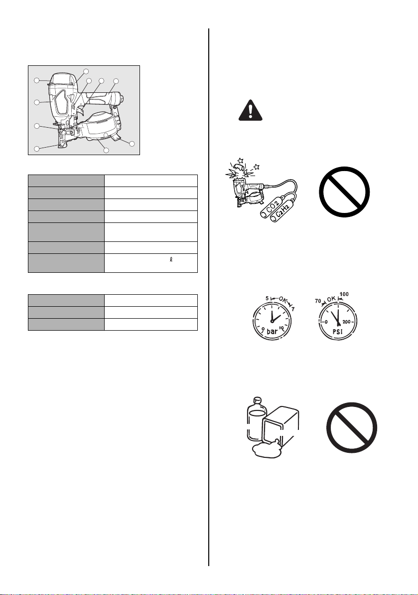
1. DO NOT USE ANY POWER SOURCE EXCEPT AN AIR COMPRESSOR
The tool is designed to operate on compressed air. Do not
operate the tool on any other highpressure gas, combustible gases (e.g., oxygen, acetylene, etc.) since there is the
danger of an explosion. For this reason, absolutely do not
use anything other than an air compressor to operate the
tool.
Thinner
3. DO NOT OPERATE THE TOOL NEAR A FLAMMABLE SUBSTANCE
Never operate the tool near a flammable substance (e.g.,
thinner, gasoline, etc.). Volatile fumes from these substances could be drawn into the compressor and compressed together with the air and this could result in an explosion.
4. NEVER USE THE TOOL IN AN EXPLOSIVE ATMOSPHERE
Sparks from the tool may ignite atmospheric gases, dust or
other combustible materials.
5. DO NOT USE A WRONG FITTINGS
The connector on the tool must not hold pressure when air
supply is disconnected. If a wrong fitting is used, the tool
can remain charged with air after disconnecting and thus
will be able to drive a fastener even after the air line is disconnected, possibly causing injury.
6. DISCONNECT THE AIR SUPPLY AND EMPTY THE MAGAZINE WHEN THE TOOL IS NOT IN USE
Always disconnect the air supply from the tool and empty
the magazine when operation has been completed or suspended, when unattended, moving to a different work area,
adjusting, disassembling, or repairing the tool, and when
clearing a jammed fastener.
Gasoline
2. OPERATE WITHIN THE PROPER AIR PRESSURE RANGE
The tool is designed to operate within an air pressure range
of 70 to 100 p.s.i. (5 to 7 bar).
The pressure should be adjusted to the type of the work being fastened. The tool shall never be operated when the operating pressure exceeds 120 p.s.i. (8.3 bar).
Never connect the tool to air pressure which potentially exceeds 200 p.s.i. (13.8 bar) as the tool can burst.
7. INSPECT SCREW TIGHTNESS
Loose or improperly installed screws or bolts cause accidents and tool damage when the tool is put into operation.
Inspect to confirm that all screws and bolts are tight and
properly installed prior to operating the tool.
4
Page 5

8. DO NOT TOUCH THE TRIGGER UNLESS YOU INTEND TO DRIVE A FASTENER
Whenever the air supply is connected to the tool, never
touch the trigger unless you intend to drive a fastener into
the work. It is dangerous to walk around carrying the tool
with the trigger pulled, and this and similar actions should
be avoided.
9. NEVER POINT THE DISCHARGE OUTLET TOWARD YOURSELF AND OTHER PERSONNEL
If the discharge outlet is pointed toward people, serious accidents may be caused when misfiring. Be sure the discharge outlet is not pointed toward people when connecting
and disconnecting the hose, loading and unloading the fasteners or similar operations.
10. USE SPECIFIED FASTENERS (SEE PAGE 7)
The use of fasteners other than specified fasteners will
cause the tool malfunction. Be sure to use only specified
fasteners when operating the tool.
13. DO NOT DRIVE FASTENERS ON TOP OF OTHER FASTENERS
Driving fasteners on the top of other fasteners may cause
deflection fasteners which could cause injury.
14. REMOVING THE FASTENERS AFTER COMPLETING OPERATION
If fasteners are left in the magazine after the completion of
operation, there is the danger of a serious accident occurring prior to the resumption of operation, should the tool be
handled carelessly, or when connecting the air fitting. For
this reason, always remove all fasteners remaining in the
magazine after completion of the operation.
15. CHECK OPERATION OF THE CONTACT TRIP MECHANISM FREQUENTLY INCASE OF USING A CONTACT
TRIP TYPETOOL
Do not use the tool if the trip is not working correctly as accidental driving of a fastener may result. Do not interfere
with the proper operation of the contact trip mechanism.
16. WHEN USING THE TOOL OUTSIDE OR ELEVATED PLACE
When fastening roofs or similar slanted surface, start fastening at the lower part and gradually work your way up.
Fastening backward is dangerous as you may lose your foot
place.
Secure the hose at a point close to the area you are going
to drive fasteners. Accidents may be caused due to the
hose being pulled inadvertently or getting caught.
11. PLACE THE DISCHARGE OUTLET ON THE WORK SURFACE PROPERLY
Failure to place the discharge outlet of the nose in a proper
manner can result in a fastener flying up and is extremely
dangerous.
12. DO NOT DRIVE FASTENERS CLOSE TO THE EDGE AND CORNER OF THE WORK AND THIN MATERIAL
The workpiece is likely to split and the fastener could fly free
and hit someone.
17. NEVER USE THE TOO L IF ANY PORTION OF THE TOOL
CONTROLS (e.g., TRIGGER, CONTACT ARM) IS INOPERABLE, DISCONNECTED, ALTERED OR NOT WOKING PROPERLY
18. NEVER ACTUATE THE TOOL INTO FREE SPACE
This will avoid any hazard caused by free flying fasteners
and excessive strain of the tool.
19. ALWAYS ASSUME THAT THE TOOL CONTAINS FASTENERS
20. RESPECT THE TOOL AS A WORKING IMPLEMENT
21. NO HORSEPLAY
22. NEVER LOAD THE TOOL WITH FASTENERS WHEN
ANY ONE OF THE OPERATING CONTROLS (e.g., TRIGGER, CONTACT ARM) IS ACTIVATED
5
Page 6

23. WHEN DISPOSING THE MACHINE OR ITS PARTS, FOLLOW THE RELEVANT NATIONAL RULES
OBSERVE THE FOLLOWING GENERAL CAUTION IN ADDITION TO THE OTHER WARNINGS
CONTAINED IN THIS MANUAL
• Do not use the tool as a hammer.
• Always carry the tool by the grip, never carry the
tool by the air hose.
• The tool must be used only for the purpose it was
designed.
• Never remove, tamper with the operating controls
(e.g., TRIGGER, CONTACT ARM)
• Keep the tool in a dry place out of reach of chil-
dren when not in use.
• Do not use the tool without Safety Warning label.
• Do not modify the tool from original design or
function without approval by MAX CO., LTD.
6
Page 7
3. SPECIFICATIONS AND TECHNI-
CAL DATA
1. NAME OF PARTS
8
1
4
3
2. TOOL SPECIFICATIONS
HEIGHT 10-5/8" (271 mm)
WIDTH 4-5/8" (116 mm)
LENGTH 12-3/8" (313 mm)
WEIGHT 5.2 lbs. (2.4 kg)
RECOMMENDED
OPERATING PRESSURE
LOADING CAPACITY 120 Nails
AIR CONSUMPTION 0.046 ft3 at 90 p.s.i. (1.3 at 6 bar)
3. FASTENER SPECIFICATIONS
NAIL LENGTH 3/4" to 1-3/4" (19 to 45 mm)
SHANK DIAMETER .120" (3.0 mm)
SHANK TYPE Smooth, Ring
2
9
6
5
7
operating pressure
1 Frame
2 Cylinder Cap
3 Contact Arm
4 Nose
5 Magazine
6 Trigger
7 Grip
8 Exhaust Port
9 Trigger Lock
Dial
0 Shingle gauge
10
70 to 100 p.s.i.
(5 to 7 bar)
5. APPLICATIONS
∗ Fastening asphalt and fiberglass shingles
∗ Siding installation
∗ Fastening lath wire on the plywood
∗ Wooden box assembly
4. AIR SUPPLY AND CONNECTIONS
WARNING
Read section titled "SAFETY INSTRUCTIONS"
DO NOT USE ANY POWER SOURCE EXCEPT AN AIR COMPRESSOR
The tool is designed to operate on compressed air. Do not operate the tool on any other highpressure gas, combustible gases
(e.g., oxygen, acetylene, etc.) since there is the danger of an explosion. For this reason, absolutely do not use anything other
than an air compressor to operate the tool.
TOOL AIR FITTINGS:
This tool uses a 1/4" N.P .T. male plug. The inside diameter should
be .28" (7 mm) or larger. The fitting must be capable of discharging
tool air pressure when disconnected from the air supply.
RECOMMENDED OPERATING PRESSURE:
70 to 100 p.s.i. (5 to 7 bar). Select the operating air pressure within this range for best fastener performance.
DO NOT EXCEED 120 p.s.i. (8 bar).
4. TECHNICAL DATA 1 NOISE
A-weighted single-event sound power level
A-weighted single-event emission sound pressure level at
work station
These values are determined and documented in accordance to EN12549 : 1999.
2 VIBRATION
Vibration characteristic value = 3.81 m/s2
These values are determined and documented in accordance to ISO 8662-11.
This value is a tool-related characteristic value and does not
represent the influence to the hand-arm-system when using
the tool. An influence to the hand-arm-system when using
the tool will for example depend on the gripping force, the
contact pressure force, the working direction, the adjustment of mains supply, the workpiece, the workpiece support.
------ LWA, 1s, d 100.7 dB
------ LpA, 1s, d 93.8 dB
OPERATE WITHIN THE PROPER AIR PRESSURE RANGE
The tool designed to operate within an air pressure range of 70
to 100 p.s.i.. (5 to 7 bar)
The pressure should be adjusted to the type of the work being
fastened. The tool shall never be operated when the operating
pressure exceeds 120 p.s.i.. (8 bar)
Thinner
DO NOT OPERATE THE TOOL NEAR A FLAMMABLE SUBSTANCE
Never operate the tool near a flammable substance (e.g., thinner,
gasoline, etc.). Volatile fumes from these substances could be
drawn into the compressor and compressed together with the air
and this could result in an explosion.
DO NOT USE A WRONG FITTINGS
The connector on the tool must not hold pressure when air supply
is disconnected. If a wrong fitting is used, the tool can remain
charged with air after disconnecting and thus will be able to drive
a fastener even after the air line is disconnected, possibly causing injury.
Gasoline
7
Page 8

DISCONNECT THE AIR SUPPLY AND EMPTY THE MAGAZINE WHEN THE TOOL IS NOT IN USE
Always disconnect the air supply from the tool and empty the
magazine when operation has been completed or suspended,
when unattended, moving to a different work area, adjusting, disassembling, or repairing the tool, and when clearing a jammed
fastener.
[AIR SUPPLY & CONNECTIONS]
Air compressor
Air hose
Air filter
Regulator
Oiler
5. INSTRUCTIONS FOR OPERATION
Read section titled "SAFETY INSTRUCTIONS".
1. BEFORE OPERATION
Check the following prior operation.
1 Wear Safety Glasses or Goggles. 2 Do not connect the air supply. 3 Inspect screw tightness. 4 Check operation of the contact arm & trigger if moving
smoothly.
5 Connect the air supply. 6 Check the air-leakage. (The Tool must not have the air-
leakage.)
7 Hold the Tool with finger-off the trigger, then push the con-
tact arm against the work-piece. (The tool must not operate.)
8 Hold the Tool with contact arm free from work-piece and pull
the trigger. (The Tool must not operate.)
9 Disconnect the air supply.
3-piece airset
Used at 70 to 100 p.s.i. (5 to 7 bar)
FITTINGS: Install a male plug on the tool which is free flowing
and which will release air pressure from the tool when disconnected from the supply source.
HOSES: Hose has a min. ID of 1/4" (6 mm) and max. length of
no more than 17" (5 meters).
The supply hose should contain a fitting that will provide "quick
disconnecting" from the male plug on the tool.
SUPPLY SOURCE: Use only clean regulated compressed air as
a power source for the tool.
3-PIECE AIRSET (Air filter, Regulator, Oiler):
Refer to TOOL SPECIFICATIONS for setting the correct operating pressure for the tool.
NOTE:
A filter will help to get the best performance and minimum wear
from the tool because dirt and water in the air supply are major
causes of wear in the tool.
Frequent, but not excessive, lubrication is required for the best
performance. Oil added thru the air line connection will lubricate
the internal parts.
WARNING
2. OPERATION
Wear safety glasses or goggles danger to the eyes always exists
due to the possibility of dust being blown up by the exhausted air
or of a fastener flying up due to the improper handling of the tool.
For these reasons, safety glasses or goggles shall always be
worn when operating the tool.
The employer and/or user must ensure that proper eye protection
is worn. Eye protection equipment must conform to the requirements of the American National Standards Institute, ANSI Z87.1
(Council Directive 89/686/EEC of 21 DEC. 1989) and provide
both frontal and side protection.
The employer is responsible to enforce the use of eye protection
equipment by the tool operator and all other personnel in the work
area.
NOTE: Non-side shielded spectacles and face shields alone do
not provide adequate protection.
WARNING
Keep hands and body away from the discharge outlet when driving the fasteners because of dangerous of hitting the hands or
body by mistake.
8
Page 9

NAIL LOADING
Door latch
Magazine cover
Door
1 Open the magazine:
Pull down door latch and swing door open. Swing magazine
cover open.
Nail support
Magazine
2 Check adjustment:
The nail support can be moved up and down to four settings. To change setting pull up on the post and twist to the
correct step. The nail support should be adjusted correctly
to the position as follows;
1-3/4" (45 mm) nails - use bottom step
1-1/4", 1-1/2" (32, 38 mm) nails - use middle step
3/4", 7/8", 1" (19, 22, 25 mm) nails - use top step
Nail
Feed pawl
3 Nail loading:
Place a coil of nails over the post in the Magazine. Uncoil
enough nails to reach the Feed Pawl, and place the second
nail between the teeth on the Feed Pawl. The nail heads fit
in slot on nose.
4 Swing Cover closed. 5 Close the Door.
Check that latch engages. (If it does not engage, check that
the nail heads are in the slot on the Nose).
TEST OPERATION
1 Adjust the air pressure at 70 p.s.i. (5 bar) and connect the
air supply.
2 Without touching the Trigger, depress the Contact Arm
against the work-piece.
Pull the Trigger. (The tool must fire the fastener.)
3 With the tool off the work-piece, pull the Trigger.
Then depress the Contact Arm against the work-piece.
(The tool must fire the fastener.)
4 Adjust the air pressure as much as the lowest possible ac-
cording to the diameters and length of fastener and the
hardness of work-piece.
DRIVING DEPTH ADJUSTMENT DIAL
Adjustment dial
WARNING
• ALWAYS disconnect air supply before Adjust-
ment dial.
1 With air pressure set, drive nails into a representative mate-
rial sample to determine if adjustment is necessary.
2 If adjustment is required, disconnect air supply.
9
Page 10

3 Refer to the mark on the Contact Arm cover for direction to
turn the Adjustment dial.
Deeper Shallower
4 Reconnect air supply.
Deeper Shallower
TRIGGER LOCK MECHANISM
Trigger lock dial
Trigger
SHINGLE GAUGE
Shingle exposure
WARNING
• ALWAYS disconnect the air supply before mak-
ing adjustment.
This gauge can be used to control shingle spacing. Loosen the
screw to adjust gauge to desired shingle exposure, as shown.
CLEANING THE ROOFING NAILER
The tool is equipped with a trigger lock mechanism. Push and rotate the Trigger Lock Dial to the trigger free position before driving
nails.
WARNING
• Do not use gasoline or similar highly flammable
liquids to clean the nailer.
Vapor could be ignited by a spark causing an explosion.
Tar and dirt may build up on the Nose and Contact Arm. This can
prevent correct operation. Remove any build-up with kerosene,
#2 fuel oil or diesel fuel. Do not dunk the nailer into these solvents
beyond the height of the nail heads, to avoid getting the solvent
into the drive cylinder.
Dry off the nailer before use. Any oil film left after cleanup will accelerate the tar buildup, and the nailer will require more frequent
re-cleaning.
NOTE:
Solvent s sprayed on Nos e to clean and free up the tri p may have
the opposite effect! The solvent may soften the tar on the shingles and cause tar build-up to be accelerated. Dry operation is
better, as noted above.
10
Page 11

MODEL IDENTIFICATION
CONTACT TRIP
The common operating procedure on "Contact Trip" tools is for
the operator to contact the work to actuate the trip mechanism
while keeping the trigger pulled, thus driving a fastener each time
the work is contacted. This will allow rapid fastener placement on
many jobs, such as sheathing, decking and pallet assembly.
All pneumatic tools are subject to recoil when driving fasteners.
The tool may bounce, releasing the trip, and if unintentionally allowed to recontact the work surface with the trigger still actuated
(finger still holding trigger pulled) an unwanted second fastener
will be driven.
CONTACT TRIP Identified by BLACK TRIGGER.
SEQUENTIAL TRIP (Optional kit)
The Sequential Trip requires the operator to hold the tool against
the work before pulling the Trigger. This makes accurate fastener
placement easier, for instance on framing, toe nailing and crating
applications. The Sequential Trip allows exact fastener location
without the possibility of driving a second fastener on recoil, as
described under "Contact Trip".
The Sequential Trip Tool has a positive safety advantage because it will not accidentally drive a fastener if the tool is contacted against the work-or anything else-while the operator is holding
the Trigger pulled.
SEQUENTIAL TRIP Identified by ORANGE TRIGGER.
CONTACT TRIP WITH ANTI-DOUBLE FIRE MECHANISM Identified by RED TRIGGER.
CONTACT FIRE OPERATION
For contact fire operation, hold the Trigger and depress the Contact Arm against the work surface.
SINGLE FIRE OPERATION (ANTI-DOUBLE FIRE MECHANISM)
For single fire operation, depress the Contact Arm against the
work surface and pull the Trigger.
Tool cannot fire a second nail until the Trigger is released and
tool can cycle.
DRIVING FASTENERS
CONTACT FIRE OPERATION (CONTACT TRIP)
For contact fire operation, hold the Trigger and depress the Contact Arm against the work surface.
1
2
CONTACT TRIP WITH ANTI-DOUBLE FIRE MECHANISM
(Optional kit)
(US patent 5597106, UK patent 2286790)
The common operating procedure on "Contact Trip" tools is for
the operator to contact the work to actuate the trip mechanism
while keeping the trigger pulled, thus driving a fastener each time
the work is contacted. This will allow rapid fastener placement on
many jobs, such as sheathing, decking and pallet assembly.All
pneumatic tools are subject to recoil when driving fasteners. The
tool may bounce, releasing the trip,and if unintentionally allowed
to recontact the work surface with the trigger still actuated (finger
still holding trigger pulled) an unwanted second fastener will be
driven.
PROCEDURE
1 Hold the Trigger. 2 Depress the Contact Arm.
11
Page 12

6. MAINTAIN FOR PERFORMANCE
1 DO NOT FIRE THE NAILER WHEN IT IS EMPTY 2 USE A 3-PIECE AIRSET
Failure to use a 3-piece airset allows the moisture and dirt inside
compressor to pass into the tool directly. This causes rust and
wear, and results in a poor operating performance. The hose
length between airset and tool should be no longer than 5 m since
a longer length results in a reduction in air pressure.
3 USE RECOMMENDED OIL
The velocite or turbine oil should be used to lubricate the tool.
Upon completion of operations, place 2 or 3 drops of oil into the
Air Plug inlet with the jet oiler. (Recommended Oil : ISO VG32)
4 INSPECT AND MAINTAIN DAILY OR BEFORE OPERA-
TION
WARNING
Disconnect air supply and empty the Magazine when inspecting or maintaining the tool.
(1) Drain air line filter and compressor
(2) Keep lubricator filled in air 3-pieces set
(3) Clean filter element of air 3-pieces set
(4) Tighten all screws
(5) Keep Contact Arm moving smoothly
7. STORING
1 When not in use for an extended period, apply a thin coat of
the lubricant to the steel parts to avoid rust.
2 Do not store the tool in a cold weather environment. Keep
the tool in a warm area.
3 When not in use, the tool should be stored in a warm and
dry place. Keep out of reach of children.
4 All quality tools will eventually require servicing or replace-
ment of parts because of wear from the normal use.
8. TROUBLE SHOOTING/REPAIRS
The troubleshooting and/or repairs shall be carried out only by
the MAX CO., LTD. authorised distributors or by other specialists.
Supplement to the operating instruction
According to the European Norm EN 792-13 the regulation is valid from 01.01.2001 that all fastener driving tools with contact actuation must be marked with the symbol "Do not use on
scaffoldings, ladders" and they shall not be used for specific application for example:
∗ when changing one driving location to another involves the
use of scaffoldings, stairs, ladders or ladder alike constructions e.g. roof laths,
∗ closing boxes or crates,
∗ fitting transportation safety systems e.g. on vehicles and wag-
ons.
12
Page 13

FRANÇAIS
MANUEL D’UTILISATION ET D’ENTRETIEN
INDEX
1. CONSIGNES DE SECURITE GENERALES......................................13
2. CONSIGNE DE SECURITE ...............................................................14
3. CARACTERISTIQUES TECHNIQUES ET ACCESSOIRES .............17
4. ALIMENTATION EN AIR COMPRIME ET CONNEXIONS ................17
5. INSTRUCTIONS D’EMPLOI ..............................................................18
6. ENTRETIEN POUR OBTENIR LES MEILLEURES PERFORMANCES.....22
7. EMMAGASINAGE..............................................................................22
8. REPARATION....................................................................................22
AVANT D’UTILISER CE COMPRESSEUR, LIRE CE MANUEL ET LES CONSIGNES DE SECURITE AFIN DE
GARANTIR UN FONCTIONNEMENT SUR.
AVERTISSEMENT
CONSERVER CE MANUEL EN LIEU SUR AVEC L’OUTIL AFIN DE POUVOIR LE CONSULTER ULTERIEUREMENT.
1. CONSIGNES DE SECURITE GENERALES
AVERTISSEMENT
LIRE TOUTES LES CONSIGNES DE
SECURITE ET TOUTES LES INSTRUCTIONS.
Un non-respect des consignes et des instructions
peut entraîner la mort ou des blessures graves.
Conserver toutes les consignes et
instructions pour une consultation ultérieure.
1. PORTEZ DES LUNETTES PROTECTRICES OU DE SÉCURITÉ
Un danger aux yeux est toujours présent provenant de la
poussière rejetée par l’air s’échappant ou de l’éjection de
clous à cause d’une manipulation incorrecte de l’outil. Dans
ce cas, il est nécessaire de porter toujours des lunettes
protectrices ou de sécurité quand l’outil est utilisé.
L’employeur et/ou l’usager doivent assurer une protection
appropriée des yeux des opérateurs de l’outil.
L’équipement de protection des yeux doit répondre aux
exigences du American National Standards Institute,
Norme ANSI Z87.1 (Directive du Conseil 89/686/CEE du 21
décembre 1989) et assurer une protection frontale et
latérale de la tête.
L’employeur est responsable pour imposer l’usage de
l’équipement de protection des yeux par l’opérateur de
l’outil et par tous les autres membres du personnel dans la
surface de travail.
REMARQUE : Les lunettes sans protection latérale et
frontale n’assurent pas une protection correcte.
2. DANS CERTAINS ENVIRONNEMENTS UNE PROTECTION AUDITIVE PEUT ETRE EXIGEE
Etant donné que les conditions de travail peuvent entraîner
une exposition à des niveaux de bruit élevés qui peuvent
provoquer des dommages d’audition, l’employeur et
l’utilisateur doivent s’assurer qu’un équipement de protection
auditive est mis à disposition et utilisé par l’opérateur et les
autres personnes se trouvant sur le lieu de travail.
13
Page 14

3. ELOIGNER VOTRE CORPS ET VOS MAINS DU NEZ DE L’APPAREIL
Lors du chargement et de l’utilisation de l’outil, ne jamais
placer votre main ou une partie de votre corps dans la zone
de décharge de l’élément de fixation de l’outil. It is very
dangerous to hit the hands or body by mistake.
Diluant
3. NE PAS UTILISER L’OUTIL PRES D’UNE SUBSTANCE INFLAMMABLE
Ne jamais utiliser l’outil près d’une substance inflammable
(ex. diluant, de l’essence, etc.). Les fumées volatiles de ces
substances peuvent être attirées dans le compresseur,
comprimées en même temps avec l’air, cela risquant de
produire une explosion.
4. N’UTILISEZ JAMAIS L’OUTIL DANS UNE AMBIANCE EXPLOSIVE
Les étincelles de l’outil peuvent mettre à feu les gaz
atmosphériques, la poussière ou d’autres matériaux
combustibles.
Essence
4. NE PAS UTILISER SUR DES ECHAFAUDAGES OU DES ECHELLES
Ne pas utiliser sur des échafaudages et des échelles avec
des machines à enfoncer les fixations équipées d'une
commande par contact ou par contact continu.
2. CONSIGNE DE SECURITE
1. NE PAS UTILISER D’AUTRE SOURCE D’ALIMENTATION QU’UN COMPRESSEUR D’AIR
L’outil est concu pour fonctionner avec de l’air comprimé.
Ne pas utiliser l’outil avec d’autres gaz sous haute pression,
des gaz combustibles (ex. l’oxygène, l’acétylène, etc.), car
il y a risque d’explosion. Par conséquent, ne rien utiliser
d’autre que le compresseur d’air pour faire fonctionner cet
outil.
2. RESPECTER LA PLAGE DE PRESSION D’AIR APPROPRIEE POUR L’UTILISATION
L’outil est concu pour fonctionner dans une plage de
pression de 70 to 100 p.s.i. (5 à 7 bar).
La pression doit être ajustée au type de pièce à clouer.
L’outil ne doit jamais être utilisé lorsque la pression de
fonctionnement dépasse 120 p.s.i. (8,3 bar).
Ne jamais brancher d’outil sur l’alimentation en air
comprimé dont la pression peut éventuellement dépasser
200 p.s.i. (13,8 bars), l’outil risquant d’exploser.
5. NE PAS UTILISER DES ELEMENTS DE FIXATION INADEQUATS
Le connecteur sur l’outil ne doit pas retenir la pression
lorsque l’admission d’air est débranchée. Si une fixation
non appropriée est utilisée, l’outil peut rester chargé d’air
après le débranchement et sera ainsi capable d’enfoncer
un élément de fixation même après le débranchement de
l’arrivée d’air, provoquant ainsi des dommages éventuels.
6. COUPER L’ALIMENTATION EN AIR COMPRIME ET VIDER LE MAGASIN LORSQUE L’OUTIL N’EST PAS UTILISE
Veillez à toujours débrancher l’arrivée d’air de l’outil et à
vider le magasin en fin de travail ou lorsque le travail est
suspendu, lorsque l’outil est laissé sans surveillance, est
déplacé vers un autre lieu de travail, réglé, démonté ou
réparé, ou encore lorsque vous dégagez un fermoir.
7. CONTROLER LE SERRAGE DES VIS
Des vis ou des boulons desserrés ou incorrectement
installés peuvent provoquer des accidents et endommager
l’outil lorsqu’il est mis en service. Contrôler et vérifier que
tous les vis et boulons sont bien serrés et correctement
installés avant d’utiliser l’outil.
14
Page 15

8. NE PAS TOUCHER LE DECLENCHEUR SAUF POUR ENFONCER UN ELEMENT DE FIXATION
Chaque fois que l’arrivée d’air est connectée à l’outil, ne jamais
toucher le déclencheur sauf si on a l’intention d’enfoncer des
éléments de fixation dans la pièce. ll est dangereux de porter
l’outil tout en mar chant avec le déclencheur enclenché. Ceci,
ainsi que des actions similaires doivent être évités.
9. NE JAMAIS DIRIGER L’ORIFICE DE REFOULEMENT VERS VOUS OU VERS UNE AUTRE PERSONNE
En cas de râté, les personnes qui se trouveraient dans la
trajectoire de l’orifice de refoulement risquent d’être
grièvement blessées. Lorsque vous branchez ou
débranchez le tuyau, montez ou démontez les fermoirs ou
effectuez une intervention quelconque, vérifiez toujours que
l’orifice de refoulement n’est orienté vers personne.
10. UTILISER LES ELEMENTS DE FIXATION APPROPRIÉS (SEE PAGE 17)
L’utili sation d’éléments de fixation autres que ceux spécifiés
provoque le mauvais fonctionnement de l’outil. Sassurer d’utiliser
uniquement les éléments de fixation appropriés avec l’outil.
11. PLACER CORRECTEMENT LA SORTIE DE DÉCHARGE SUR LA SURFACE DE TRAVAIL
Si l’on oublie de placer la sortie de décharge du nez de
façon appropriée, on risque d’avoir comme conséquence
un détachement violent de l’attache vers le haut et ceci est
extrêmement dangereux.
13. NE PAS ENFONCER DES POINTES OU AGRAFES SUR D’AUTRES ELEMENTS DE FIXATION
Le fait d’enfoncer des éléments de fixation par dessus
d’autres éléments de fixation risque de provoquer un
éclatement de ces élément qui pourrait provoquer des
blessures.
14. RETRAIT DES PROJECTILES APRES LA FIN DE L’OPERATION
Si les projectiles sont laissés dans le magasin après la fin
de l’opération, il y a danger d’accident grave qui risque de
se produire avant la reprise de l’opération, au cas où l’outil
est manipulé négligemment ou lors du branchement de la
fixation d’air. Par conséquent, toujours enlever tous les
projectiles restant dans le changeur après la fin de
l’opération.
15. VERIFIER FREQUEMMENT LE FONCTIONNEMENT DU MECANISME DE DECLENCHEMENT AU COUP A COUP EN CAS D’UTILISATION D’UN OUTIL DE TYPE A DECLENCHEMENT AU COUP A COUP
Ne pas utiliser l’outil si le déclencheur ne fonctionne pas
correctement, car un enfoncement accidentel d’un
projectile de fixation risque de se produire. Ne pas gêner le
fonctionnement correct du mécanisme de déclenchement
au coup à coup.
16. UTILISATION DE L’OUTIL A L’EXTERIEUR OU SUR UN ENDROIT SURELEVE
Pour fixer un toit, ou une surface similaire inclinée,
commencer la fixation sur la partie inférieure et exécuter le
travail en montant progressivement. ll est dangereux de
faire des fixations en reculant, car on risque de perdre pied
en glissant.
Fixer le tuyau à un point près de la zone où les éléments de
fixation doivent être enfoncés. Des accidents risquent de se
produire à cause d’un tuyau coincé ou tiré par inadvertance.
17. NE JAMAIS UTILISER L’OUTIL SI N’IMPORTE QUELLE PARTIE DES COMMANDES D’OUTIL (PAR EXEMPLE, DÉCLENCHEUR, BRAS DE CONTACT) EST INOPÉRABLE, DÉBRANCHÉE, CHANGÉE OU NE FONCTIONNANT PAS CORRECTEMENT
18. NE JAMAIS LANCER LES POINTES DANS UN ESPACE LIBRE
Les pointes voltigeant dans l’air présentent un certain
danger;
12. NE PAS APPLIQUER LES ELEMENTS DE FIXATION PRES DU BORD DE LA PIECE ET SUR UN MATERIAU MINCE
La pièce a tendance à éclater et l’élément de fixation risque de
sauter et de heurter quelqu’un. Faire attention lors de la fixation
d’un matériau mince ou près des bords et des coins de la pièce.
19. TOUJOURS PRÉSUMER QUE L’OUTIL EST MUNIS DE FERMOIRS
20. CONSIDEREZ L’OUTIL COMME UN INSTRUMENT DE TRAVAIL
15
Page 16

21. NE FAITES PAS DE GESTES BRUSQUES
22. NE JAMAIS MONTER LES FERMOIRS SUR L’OUTIL LORSQU’UNE COMMANDE (DÉTENTE OU BRAS DE CONTACT par exemple) EST ACTIVÉE
23. LORSQUE LA MACHINE OU SES PIECES SONT MISES AU REBUT, SUIVEZ LES REGLEMENTS NATIONAUX RELATIFS
RESPECTER LES PRECAUTIONS GENERALES
SUIVANTES EN PLUS DES AUTRES
AVERTISSEMENTS DECRITS DANS CE
MANUEL
• Ne pas utiliser l’outil comme un marteau.
• Saisissez toujours l’outil par la poignée, et ne le
transportez jamais en tenant les tuyaux d’air.
• L’outil doit être utilisé uniquement pour l’usage
préconisé.
• Ne jamais retirer ou altérer les commandes
(DÉTENTE OU BRAS DE CONTACT par exemple).
• Conserver l’outil dans un endroit sec, hors de
portée des enfants, lorsqu’il n’est pas utilisé.
• Ne pas utiliser l’outil sans l’étiquette de sécurité.
• Ne pas modifier la conception originale ou les
caractéristiques de l’outil sans le consentement
de MAX CO. LTD.
16
Page 17

3. CARACTERISTIQUES
TECHNIQUES ET ACCESSOIRES
1. NOM DES PIÈCES
8
1
4
3
2. SPÉCIFICATIONS DE L’OUTIL
Hauteur 10-5/8" (271 mm)
Largeur 4-5/8" (116 mm)
Longeur 12-3/8" (313 mm)
Poids 2,4 kg
Pression de service
recommandée
Capacite de charge 120 Pointes
Consommation en air
comprimé
3. SPÉCIFICATS DU MATÉRIEL DE FIXATION
Longueur de pointe 3/4" à 1-3/4" (19 à 45 mm)
Diamètre de tige .120" (3,0 mm)
Type de queue Droite, annulaire
2
9
6
5
pieds 3 à 90 p.s.i. (1,3 à 6 barres)
1 Boîtier
2 Couvercle de
7
Pression de fonctionnement 0,046
cylindre
3 Barre de contact
4 Nez
5 Magasin
6 Levier de
commande
7 Poignée
8 Orifice
d'échappement
10
9 Blocage de la
commande
0 Jauge de bardeau
70 à 100 p.s.i. (5 à 7 bar)
l’on utilise l’outil dépendra, par exemple, de la force de
saisie, la force de pression de contact, la direction de
fonctionnement, le réglage de l’air principal, la pièce de
travail, le support de pièce de travail.
5. APPLICATIONS
∗ Fixation de bardeaux en asphalte et fibre de verre
∗ Installation de parement
∗ Fixation de câble pour lattis sur le contreplaqué
∗ Assemblage de boîtes en bois
4. ALIMENTATION EN AIR COMPRIME ET CONNEXIONS
AVERTISSEMENT
Lire le paragraphe intitulé “CONSIGNES DE
SECURITE”
NE PAS UTILISER D’AUTRE SOURCE D’ALIMENTATION
QU’UN COMPRESSEUR D’AIR
L’outil est concu pour fonctionner avec de l’air comprimé. Ne pas
utiliser l’outil avec d’autres gaz sous haute pression, des gaz
combustibles (ex. l’oxygène, l’acétylène, etc.), car il y a risque
d’explosion. Par conséquent, ne rien utiliser d’autre que le
compresseur d’air pour faire fonctionner cet outil.
PIECES DE RACCORDEMENT D’AIR
COMPRIME :
Cet appareil est équipé d’une prise mâle avec filet extérieur de
1/4" min. Le diamètre intérieur devrait être de 0,28" (7 mm) au
moins. Le raccord doit permettre de décharger l’air comprimé de
l’appareil lorsque l’alimentation en air comprimé est interrompue.
PRESSION DE SERVICE RECOMMANDEE:
De 70 à 100 p.s.i. (5 à 7 bar) Régler l’air comprimé à l’intérieur de cette
plage pour garantir la meilleure performance possible de fixation.
LA PRESSION DE SERVICE NE DOIT PAS DEPASSER 8 BARS
(120 p.s.i.)
4. CARACTÉRISTIQUES TECHNIQUES 1 BRUIT
Niveau de puissance sonore puls ée par rapport à la courbe A
Niveau de pression acoustique pulsée par rapport à la courbe A
Ces valeurs out été calculées et documentées, en
conformité avec EN12549:1999.
2 VIBRATIONS
Valeur caractéristique de vibration = 3,81 m/s2
Ces valeurs sont déterminées et documentées
conformément à la norme ISO 8662-11.
Cette valeur représente une valeur caractéristique connexe
à l’outil et non l’influence au système main-bras lorsque l’on
utilise l’outil. Une influence au système main-bras lorsque
------ LWA, 1s, d 100,7 dB
------ LpA, 1s, d 93,8 dB
RESPECTER LA PLAGE DE PRESSION D’AIR APPROPRIEE
POUR L’UTILISATION
L'outil est conçu pour fonctionner dans une plage de pression de
70 à 100 p.s.i. (5 à 7 bar).
La pression doit être ajustée au type de pièce à clouer. L'outil ne
doit jamais être utilisé lorsque la pression de fonctionnement
dépasse 8 bar.
Diluant
NE PAS UTILISER L’OUTIL PRES D’UNE SUBSTANCE
INFLAMMABLE
Ne jamais utiliser l’outil près d’une substance inflammable (ex.
diluant, de l’essence, etc.). Les fumées volatiles de ces
substances peuvent être attirées dans le compresseur,
comprimées en même temps avec l’air, cela risquant de produire
une explosion.
Essence
17
Page 18

NE PAS UTILISER DES ELEMENTS DE FIXATION
INADEQUATS
Le connecteur sur l’outil ne doit pas retenir la pression lorsque
l’admission d’air est débranchée. Si une fixation non appropriée
est utilisée, l’outil peut rester chargé d’air après le
débranchement et sera ainsi capable d’enfoncer un élément de
fixation même après le débranchement de l’arrivée d’air,
provoquant ainsi des dommages éventuels.
COUPER L’ALIMENTATION EN AIR COMPRIME ET VIDER LE
MAGASIN LORSQUE L’OUTIL N’EST PAS UTILISE
Veillez à toujours débrancher l’arrivée d’air de l’outil et à vider le
magasin en fin de travail ou lorsque le travail est suspendu,
lorsque l’outil est laissé sans surveillance, est déplacé vers un
autre lieu de travail, réglé, démonté ou réparé, ou encore lorsque
vous dégagez un fermoir.
5. INSTRUCTIONS D’EMPLOI
Lire le paragraphe intitulé “CONSIGNES DE
SECURITE”.
1. AVANT DE TRAVAILLER:
Vérifiez les points suivants avant d’utiliser l’outil.
1 Mettre les lunettes de protection. 2 Ne pas encore brancher l’alimentation en air comprimé. 3 Vérifier la bonne assise des vis. 4 Vérifier le fonctionnement de la barre de contact et
s’assurer que le levier de commande se déplace librement.
5 Brancher l’alimentation en air comprimé. 6 Rechercher l’éventuelle présence d’une fuite d’air.
(L’appareil ne doit pas avoir de fuite d’air.)
7 Tenir l’outil (ne pas mettre de doigt sur le levier de
commande) et appuyer la barre de contact contre la pièce
à fixer. (L’outil ne doit pas fonctionner.)
8 Tenir l’outil en sorte que la barre de contact ne repose pas
sur la pièce à fixer et appuyer sur le levier de commande.
(L’outil ne doit pas fonctionner.)
9 COUPER L’ALIMENTATION EN AIR COMPRIME ET
VIDER LE MAGASIN LORSQUE L’OUTIL N’EST PAS
UTILISE.
[ARRIVEE D’AIR ET RACCORDEMENTS]
Regulateur
Tuyau
Pression 70 à 100 p.s.i. (5 à 7 bar)
FIXATIONS : Installer le raccord mâle sur l’outil, qui est à flux
libre et qui relâche la pression d’air de l’outil lorsqu’il est
débranché de la source d’alimentation.
TUYAUX : Le diamètre intérieur du tuyau doit être de 1/4" (6 mm)
min. et d’une longueur maximale de 17" (5 mètres).
Le tuyau d’alimentation doit avoir une fixation qui assure un
“débranchement rapide” de la fiche mâle sur l’outil.
SOURCE D'ALIMENTATION : Utiliser uniquement l’air
comprimé régulé comme source d’alimentation pour l’outil.
ENSEMBLE DE REGULATION (Filtre à air, mano-detendeur,
graisseur):
Se référer aux SPECIFICATIONS DE L’OUTIL pour le réglage de
la pression de fonctionnement appropriée pour l’outil.
REMARQUE:
Un filtre assure une meilleure performance et un minimum
d’usure de l’outil, parce que l’encrassement et l’eau dans l’arrivée
d’air sont les sources principales d’usure de l’outil.
Des graissages fréquents, mais non excéssifs sont nécessaires
pour conserver la meilleure performance. L’huile ajoutée à
travers le raccord de ligne d’air lubrifie les pièces internes.
Regulateur
Filtre
Ensemble de regulation
Graisseur
AVERTISSEMENT
2. TRAVAILLER
Un danger aux yeux est toujours présent provenant de la
poussière rejetée par l’air s’échappant ou de l’éjection de clous à
cause d’une manipulation incorrecte de l’outil. Dans ce cas, il est
nécessaire de porter toujours des lunettes protectrices ou de
sécurité quand l’outil est utilisé.
L’employeur et/ou l’usager doivent assurer une protection
appropriée des yeux des opérateurs de l’outil. L’équipement de
protection des yeux doit répondre aux exigences du American
National Standards Institute, Norme ANSI Z87.1 (Directive du
Conseil 89/686/CEE du 21 décembre 1989) et assurer une
protection frontale et latérale de la tête.
L’employeur est responsable pour imposer l’usage de
l’équipement de protection des yeux par l’opérateur de l’outil et
par tous les autres membres du personnel dans la surface de
travail.
REMARQUE : Les lunettes sans protection latérale et frontale
n’assurent pas une protection correcte.
AVERTISSEMENT
Veillez à tenir les mains et le reste du corps hors de portée de
l’ouverture de sortie pendant l’agrafage/le pointage pour éviter de
toucher accidentellement les mains ou le corps.
18
Page 19

CHARGEMENT DE CLOUS
Fermeture de porte
Capot de magasin
Porte
1 Ouvrir le magasin :
Tirer le dispositif de fermeture de porte et pivoter la porte
pour l'ouvrir. Pivoter le capot du magasin pour l'ouvrir.
Support de
pointes
Magasin
2 Vérifier le réglage :
Le support de pointes peut être déplacé vers le haut et le
bas sur quatre réglages. Pour modifier le réglage, tirer le
support vers le haut et le tourner jusqu'au cran souhaité. Le
support de pointes doit être réglé correctement comme
suit :
Clous de 1-3/4" (45 mm) - utiliser le cran inférieur
Clous de 1-1/4", 1-1/2" (32, 38 mm) - utiliser le cran du
milieu
Clous de 3/4", 7/8", 1" (19, 22, 25 mm) - utiliser le cran
supérieur
Clou
Cliquet d'avance
3 Chargement des clous :
Placer une bobine de clous sur le support du magasin.
Dérouler un nombre suffisant de clous pour atteindre le
cliquet d'avance, et placer le second clou entre les dents du
cliquet d'avance. Les têtes de clou s'adaptent dans la fente
du nez.
4 Capot pivotant fermé. 5 Fermer la porte.
Vérifier que le dispositif de fermeture s'engage. (S'il ne
s'engage pas, vérifier que les têtes de clou sont bien
installées dans la fente sur le nez).
TEST
1 Régler l’air comprimé sur 70 p.s.i. (5 bars) et brancher
l’alimentation en air comprimé.
2 Appuyer la barre de contact contre la pièce à fixer sans
cependant toucher au levier de commande.
Tirer le déclencheur. (L’outil doit tirer la pointe.)
3 Appuyer sur le levier de commande, l’outil ne devant pas
toucher la pièce à fixer.
Appuyer ensuite la barre de contact contre la pièce à fixer.
(L’outil doit tirer la pointe.)
4 Régler la pression atmosphérique à un niveau aussi bas
que possible, selon les diamètres, la longueur de l'attache
et la dureté de la pièce de travail.
DISQUE DE RÉGLAGE DE LA PROFONDEUR
D'ENTRAINEMENT
Disque de réglage
AVERTISSEMENT
• TOUJOURS débrancher l’alimentation d’air avant
de régler le cadran.
19
Page 20

1 Enfoncer, après avoir réglé l’air comprimé, quelques
pointes dans un échantillon du matériau à fixer pour voir s’il
est nécessaire de régler la profondeur des pointes.
2 Si oui, couper l’alimentation en air comprimé. 3 Se référer à la marque sur le capot de la barre de contact
pour la direction de rotation du cadran de réglage.
Plus profond Moins profond
4 Rebrancher l’alimentation en air comprimé.
Plus profond Moins profond
MODE D’EMPLOI DU MÉCANISME DE BLOCAGE DU
DÉCLENCHEUR
Blocage de la
commande
JAUGE DE BARDEAU
Exposition du bardeau
AVERTISSEMENT
• TOUJOURS débrancher l’alimentation d’air avant
tout réglage.
Cette jauge peut être utilisée pour contrôler l'espacement des
bardeaux. Desserrer la vis pour régler la jauge selon l'exposition
de bardeau souhaitée, comme illustré.
NETTOYAGE DU CLOUEUR DE TOITURE
Levier de
commande
Cet appareil est équipé d’un mécanisme de blocage du
déclencheur. Appuyer sur le mécanisme de blocage de la
commande et le tourner afin de le libérer avant d’utiliser
l’appareil.
AVERTISSEMENT
• Ne pas utiliser d'essence ou de liquides similaires
inflammables pour nettoyer le cloueur.
Une étincelle pourrait enflammer la vapeur et entraîner une
explosion.
Du goudron et de la saleté pourraient s'accumuler sur le nez et la
barre de contact. Ceci peut gêner le fonctionnement. Eliminer
toute accumulation à l'aide de kérosène, de fioul n° 2 ou de
carburant diesel. Ne pas tremper le cloueur dans ces solvants
au-delà de la hauteur des têtes de clous, afin d'éviter que du
solvant pénètre dans le cylindre d'entraînement.
Sécher le cloueur avant de l'utiliser. La présence d'une pellicule
d'huile a près le nettoyage a ccélère l'accumulation de goudron et
le cloueur requiert plus souvent un deuxième nettoyage.
20
Page 21

REMARQUE:
Les solvants pulvérisés sur le nez pour nettoyer et libérer le
déclencheur peuvent avoir l'effet contraire. Le solvant peut ramollir
le goudron sur les bardeaux et accél érer l'accumulation de goudron.
Un fonctionnement à sec est préférable, tel qu'indiqué ci-dessus.
IDENTIFICATION DES DIFFERENTES MODELES
DECLENCHEMENT AU COUP À COUP
La méthode de fonctionnement commune sur les outils à
“déclenchement par contact” permet à l’opérateur d’entrer en
contact avec la piè ce de travail pour actionner le déclenc heur tout en
le maintenant tiré, ceci permettant d’enfoncer un clou chaque fois
que la pièce de travail entre en contact. Ceci permettra une pose
rapide des clous sur beaucoup de pièces de travail, comme dans le
cas de mise en gaine, pose de plancher et assemblage de palettes.
Tous les outils pneumatiques sont sujets à un recul lorsque l’on
place des clous. L’outil risque de rebondir, en cas de
déclenchement, et d’entrer par mégarde en contact avec la surface
de la pièce de travail avec le déclencheur tou jours actionné (pendant
que le doigt de l’opéra teur tire toujours le déclencheur). Dans ce cas
un deuxième clou non prévu sera enfoncé.
DECLENCHEMENT AU COUP À COUP
Identifié par le DECLENCHEUR NOIR.
DECLENCHEMENT SEQUENTIEL (kit en option)
Avec le déclenche ment séquentiel, l’opérateur doit tenir l’outil contre
la pièce de travail avant de tirer le déclencheur. Ceci facilite une
pose précise des clous, par exemple dans le cas d’enca drement, de
clouage de plancher et d’assemblag e de caisses. Le déclenchement
séquentiel permet un positionnement exact des clous sans risque
d’enfoncer un deuxième clou en cas de recul, comme décrit dans le
paragraphe “Déclenchement par contact”.
L’outil de déclenchement séquentiel présente un avantage de
sécurité parce qu’il ne cause pas une pose accidentelle des clous
si l’outil entre en contact avec la pièce de travail ou toute autre
objet, pendant que l’opérateur maintient le déclencheur tiré.
DÉCLENCHEMENT SÉQUENTIEL
Identifié par le DECLENCHEUR ORANGE.
cas de mise en gaine, pose de plancher et assemblage de palettes.
Tous les outils pneumatiques sont sujets à un recul lorsque l’on
place des clous. L’outil risque de rebondir, en cas de
déclenchement, et d’entrer par mégarde en contact avec la surface
de la pièce de travail ave c le déclencheur toujours actionné (penda nt
que le doigt de l’opérateur tire toujours l e déclencheur) ; dans ce cas
un deuxième clou non prévu sera enfoncé.
MODÈLE DE DÉCLENCHEMENT PAR CONTACT AVEC
MÉCANISME DE DÉCLENCHEMENT ANTI-DOUBLE
Identifié par le DÉCLENCHEUR ROUGE.
OPÉRATION DE DÉCLENCHEMENT PAR CONTACT
Pour l’opération de déclenchement par contact, tenir le
déclencheur et enfoncer le bras de contact contre la surface de
la pièce de travail.
OPÉRATION DE DÉCLENCHEMENT SIMPLE (MÉCANISME
DE DÉCLENCHEMENT ANTIDOUBLE)
Pour l’opération de déclenchement simple, presser le bras de
contact contre la surface de la pièce de travail, puis tirer le
déclencheur.
L’outil ne peut pas déclencher un deuxième clou jusqu’à ce que
le déclencheur soit libéré et l’outil peut faire un cycle.
ATTACHE POUR ENFONCEMENT
OPÉRATION DE DÉCLENCHEMENT PAR CONTACT
(DÉCLENCHEMENT AU COUP À COUP)
Pour l’opération de déclenchement par contact, tenir le
déclencheur et enfoncer le bras de contact contre la surface de
la pièce de travail.
1
MODÈLE DE DÉCLENCHEMENT PAR CONTACT AVEC
MÉCANISME DE DÉCLENCHEMENT ANTI-DOUBLE
(kit en option)
(Brevet 5597106 USA, Brevet GB 2286790)
La méthode de fonctionnement commune sur les outils à
“déclenchement par contact” permet à l’opérateur d’entrer en
contact avec la piè ce de travail pour actionner le déclenc heur tout en
le maintenant tiré, ceci permettant d’enfoncer un clou chaque fois
que la pièce de travail entre en contact. Ceci permettra une pose
rapide des clous sur beaucoup de pièces de travail, comme dans le
2
MÉTHODE
1 Tenir le déclencheur. 2 Presser le bras de contact.
21
Page 22

6. ENTRETIEN POUR OBTENIR LES MEILLEURES PERFORMANCES
1 NE PAS DÉCLENCHER LE CLOUEUR QUAND IL EST
VIDE
2 UTILISER UN ENSEMBLE DE REGULATION Le fait de ne pas utiliser un ensemble de régulation, permet l’entrée de l’humidité et l’encrassement à l’intérieur du compresseur qui passe directement dans la cloueuse. Cela crée une formation de rouille et provoque l’usure conduisant à une mauvaise performance pendant l’utilisation. La longueur du tuyau entre le regulateur et la cloueuse ne doit pas dépasser 5 m, étant donné qu’une longueur supérieure réduit la pression d’air. 3 UTILISER UNE HUILE RECOMMANDEE L’huile de turbine fluide doit être utilisée pour lubrifier la cloueuse. Après la fin des opérations, placer 2 ou 3 gouttes d’huile dans l’entrée d’air de graisseur à jet. (Huile recommandée : ISO VG32) 4 VERIFIER ET ENTRETENIR L’OUTIL TOUS LES JOURS
OU AVANT CHAQUE UTILISATION.
AVERTISSEMENT
Couper l’alimentation en air comprimé et vider le magasin
avant toute vérification ou mesure d’entretien de l’outil.
(1) Vider le filtre de la conduite d’air et le compresseur.
(2) Veiller à ce que le graisseur soit toujours plein dans l’unité
d’air comprimé à trois éléments.
(3) Nettoyer l’élément filtrant de l’unité d’air comprimé à trois
éléments.
(4) Bien serrer toutes les vis.
(5) Faire en sorte que la barre de contact garde sa liberté de
mouvement.
8. REPARATION
Le dépistage de dérangements et/ou les réparations ne doivent
être réalisés que par des distributeurs autorisés de la société
MAX CO.,LTD. ou tout autre spécialiste qui respectera les
informations contenues ici.
Supplément au mode d’emploi
Selon Ia norme européenne EN 792-13 le réglement suivant est
valable du 1.1.2001, que toutes machines à enfoncer les
fixations équipées de commande par contact doivent être
marquées avec le symbole "Ne pas utiliser sur des échafaudages
ou e’chelles" et elles ne seront pas utilisées pour utilisations
spécifiques, par example:
∗ en cours de déplacement d’un lieu d’enfoncement à l’autre sur
des échafaudages, escaliers, échelles ou constructions de
même qu‘êchelles comme p.e. lattis du toit
∗ pour fermer des boîtes ou des caisses
∗ pour fixer des systèmes d’arrimages p.e. sur véhicules ou
wagons.
7. EMMAGASINAGE
1 Si l’outil doit rester inutilisé pendant un certain temps,
appliquer une mince couche de lubrifiant sur les pièces en
acier pour éviter l’apparition de rouille.
2 Ne pas entreposer l’outil dans un endroit exposé au froid.
Le conserver dans un endroit chaud.
3 Si l’outil reste inutilisé, il faut le conserver dans un endroit
chaud et sec. Le mettre hors de portée des enfants.
4 Même les outils de qualité peuvent éventuellement
nécessiter des mesures d’entretien ou le remplacement de
pièces en raison de l’usure normale.
22
Page 23

ESPAÑOL
MANUAL DE OPERACIONES Y MANTENIMIENTO
INDICE
1. ADVERTENCIAS GENERALES DE SEGURIDAD ...........................23
2. ADVERTENCIA DE SEGURIDAD .....................................................24
3. DATOS TECNICOS Y ACCESORIOS ...............................................27
4. EL SUMINISTRO DE AIRE Y CONEXIONES....................................27
5. INSTRUCCIONES PARA EL FUNCIONAMIENTO ...........................28
6. MANTENIMIENTO .............................................................................32
7. ALMACENAMIENTO .........................................................................32
8. SUBSANACION DE AVERIAS ..........................................................32
ANTES DE USAR EL COMPRESOR ESTUDIE ESTE MANUAL PARA CONOCER LAS ADVERTENCIAS E
INSTRUCCIONES DE SEGURIDAD.
ADVERTENCIA
CONSERVE ESTAS INSTRUCCIONES JUNTO CON LA HERRAMIENTA PARA FUTURAS CONSULTAS.
1. ADVERTENCIAS GENERALES
DE SEGURIDAD
ADVERTENCIA
LEA TODAS LAS INSTRUCCIONES Y
ADVERTENCIAS DE SEGURIDAD.
Si no respeta las siguientes advertencias e
instrucciones pueden producirse lesiones graves e
incluso la muerte.
e instrucciones para futuras consultas.
Conserve todas las advertencias
1. LLEVE GAFAS PROTECTORAS O DE SEGURIDAD
Un peligro a los ojos siempre está presente debido al polvo
rechazado por el aire o a la eyección de clavos por medio
de una manipulación incorrecta de la herramienta. En este
caso, es necesario utilizar siempre gafas protectoras o de
seguridad al operar la herramienta.
El patrono y/o el usuario deben asegurar una protección
apropiada de los ojos de los operadores de la herramienta.
El equipamiento de protección de los ojos debe responder
a las exigencias del American National Standards Institute,
Norma ANSI Z87.1 (Directiva del Consejo 89/686/CEE de
21 de diciembre de 1989) y asegurar una protección frontal
y lateral.
El patrono es responsable para imponer el uso del
equipamiento de protección de los ojos por el operador de
la herramienta y por todos los demás miembros del
personal en la superficie de trabajo.
NOTA: Las gafas sin protección lateral y frontal no
aseguran una protección correcta.
2. EN ALGUNOS CIRCUNSTANCIAS PUEDE SER NECESARIO LA PROTECCIÓN DE OÍDOS
El usuario puede ser expuesto a un nivel alto de ruido, lo cual
puede causar daños al oído. El usuario debería as egurarse de
que se emplea la p rotección necesaria, y de que sea empleado
por los demás trabajadores en la zona de trabajo.
23
Page 24

3. MANTENER LAS MANOS Y EL CUER PO ALEJADOS DE LA SALIDA DE DESCARGA
Al cargar y usar la herramienta no colocar ni la mano ni
ninguna parte del cuerpo sobre la salida de descarga, ya
que puede resultar muy peligroso. Es muy peligroso
golpear las manos o el cuerpo por error.
Aguarrás
3. NO MANEJAR LA HERRAMIENTA CERCA DE SUSTANCIAS INFLAMABLES
Nunca manejar la herramienta cerca de sustancias
inflamables (por ejemplo aguarrás, gasolina, etc.). Gases
volátiles de estas sustancias, pueden ser arrastradas
dentro del compresor y el aire comprimido puede provocar
una explosión.
4. NUNCA UTILIZAR LA HERRAMIENTA EN UN AMBIENTE EXPLOSIVO
Las chispas de la herramienta pueden poner a fuego los
gases atmosféricos, el polvo o otros materiales
combustibles.
Gasolina
4. NO UTILICE ANDAMIOS NI ESCALERAS DE MANO
No use andamios ni escaleras de mano cuando utilice
remachadoras de clavos equipadas con acción por
contacto o acción por contacto continuo.
2. ADVERTENCIA DE SEGURIDAD
1. NO UTILIZAR NINGUNA FUENTE DE ENERGÍA SALVO UN COMPRESOR DE AIRE
La herramienta esta designada para funcionar con aire
comprimido. No utilizar la herramienta con ningún otro gas
de alta presión, gases combustibles (por ejemplo, oxigeno,
acetileno, etc.) ya que existe el peligro de una explosión.
Por esta razón, es imprescindible que no se utilice otra cosa
que un compresor de aire para manejar la herramienta.
2. UTILIZAR DENTRO DEL LIMITE PRECISO DE PRESIÓN DE AIRE
La herramienta está designada para funcionar dentro de
limite de presión de aire de 70 a 100 p.s.i. (5 a 7 bar).
La presión debería ser adaptada a la clase de trabajo
indicado. La herramienta no debería ser manejada cuando
la presión sobrepasa 120 p.s.i. (8,3 bar).
No conecte la herramienta nunca a una alimentación de
aire comprimido cuya presión pueda superar posiblemente
los 200 p.s.i. (13,8 bar), ya que la herramienta podría
reventar.
5. NO UTILIZAR ACCESORIOS IMPROPIOS
El enchufe de la herramienta no debe contener presión,
cuando el suministro de aire este desconectado. Si se
utiliza un accesorio impropio, la herramienta puede
quedarse cargada con aire después de desconectar, de
este modo seguirá funcionando incluso después de haber
desconectado el suministro de aire, con la posibilidad de
causar daños.
6. MIENTRAS LA HERRAMIENTA NO ESTE EN USO, DESCONECTE LA ALIMENTACIÓN DE AIRE COMPRIMIDO Y VACÍE EL CARGADOR
Siempre desconecte el suministro de aire desde la
herramienta y vacíe el cartucho, cuando la operación ha
sido completada o está suspendida, cuando permanece sin
atender, cambiando a una área de trabajo diferente,
ajustando, desarmando o reparando la herramienta, y al
despejar un afianzador atascado.
7. COMPROBAR LA TENSIÓN DEL TORNILLO
Los tornillos flojos o mal instalados pueden causar
accidentes y daños a la herramienta, cuando se utiliza.
Compruebe que todos los tornillos estén apretados y bien
instalados antes de utilizar la herramienta.
24
Page 25

8. NO TOCAR EL DISPARADOR AL MENOS QUE TENGA INTENCIÓN DE REMACHAR UN CLAVO
Cuando el suministro de aire este conectado a la herramienta,
no tocar nunca el disparador a menos que tenga intención de
remachar un clavo. Es peligroso llevar la herramienta con
disparador apretado, y esto debe ser evitado.
9. NUNCA APUNTE LA SALIDA DE DESCARGA HACIA UD. MISMO Y OTRO PERSONAL
Si la salida de descarga es apuntada hacia personas,
pueden ocasionarse serios accidentes cuando se dispara
equivocadamente. Asegúrese de que la salida de descarga
no está apuntada hacia las personas cuando conecta y
desconecta la manguera, carga y descarga los
afianzadores u operaciones similares.
10. UTILIZAR GRAPAS ESPECIFICAS (VÉASE LA PÁGINA 27)
El uso de grapas que no sean las especificas pueden
causar la mala función de la herramienta. Asegurarse de
utilizar únicamente grapas especificas.
13. NO GRAPAR SOBRE OTRAS GRAPAS
Grapando encima de otras grapas puede causar desvío, lo
cual puede causar daños.
14. QUITAR LAS GRAPAS DESPUÉS DE COMPLETAR LA OPERACIÓN
Si se dejan las grapas puestas después de completar la
operación, existe el peligro de un accidente grave, si se
maneja la herramienta de forma descuidada, o en la hora
de conectar las instalaciones de aire. Por esta razón es
imprescindible quitar todas las grapas que sobran después
de completar la operación.
15. COMPRUEBE FRECUENTE MENTE EL FUNCIONAMIENTO DEL MECANISMO DE DISPARO POR CONTACTO EN EL CASO DE UTILIZAR UNA HERRAMIENTA DEL TIPO DE ACCIÓN POR CONTACTO.
No utilizar la herramienta si el disparador no funciona
correctamente, ya que puede grapar sin querer. No
interfiera el funcionamiento correcto del mecanismo de
disparo por contacto.
16. LA UTILIZACIÓN DE LA HERRAMIENTA AL AIRE LIBRE O EN SITIOS ELEVADOS
A la hora de grapar tejados o otras superficies inclinadas,
empezar en la parte baja y poco a poco subir. Grapar hacia
atrás es peligroso ya que se puede resbalar.
Asegurar la manguera cerca de la zona donde se va a
grapar. Accidentes pueden resultar debido a que la
manguera se enganche.
11. PONGA CORRECTAMENTE EL ENCHUFE DE DESCARGA EN LA SUPERFICIE DE TRABAJO
Si se olvida de poner el enchufe de descarga de la nariz de
manera apropiada, se puede causar una separación
violenta del sujetador para arriba y esto es
extremadamente peligroso.
12. NO GRAPAR JUNTO AL BORDE DE LAS SUPERFICIES O MATERIALES FINOS
Es probable que la superficie se divida y la grapa podría
saltar y dañar a alguien. Tener cuidado a la hora de grapar
materiales finos y los bordes y las esquinas de las
superficies.
17. NUNCA UTILICE LA HERRAMIENTA SI CUALQUIER PORCIÓN DE LOS CONTROLES DE L A HERRAMIENTA (POR EJEMPLO, DISPARADOR, BRAZO DE CONTACTO) ES INOPERABLE, DESCONECTADA, ALTERADA O NO OPERA CORRECTAMENTE
18. NO CLAVE NUNCA EN EL AIRE
De lo contrario, existe peligro por los clavos que salen
disparados, y la herramienta sufre un sobreesfuerzo
innecesario.
19. SUPONGA SIEMPRE QUE LA HERRAMIENTA CONTIENE LOS AFIANZADORES
20. RESPECTO A LAS HERRAMIENTAS COMO UN ELEMENTO DE TRABAJO
21. NO JUEGUE HACIENDO BROMAS
22. NUNCA CARGUE LA HERRAMIENTA CON LOS AFIANZADORES CUANDO CUALQUIERA DE LOS CONTROLES DE OPERACIÓN (ej.: DISPARADOR, BRAZO DE CONTACTO) SE ENCUENTRA ACTIVADO
25
Page 26

23. CUANDO LA MÁQUINA O SUS PIEZAS SE PONEN AL RECHAZO, POR FAVOR SIGUE LOS REGLAMENTOS NACIONALES RELATIVOS
OBSERVAR LAS SIGUIENTES PRECAUCIONES,
ASÍ COMO LAS OTRAS ADEVERTENCIAS QUE
SE RECOGEN EN ESTE MANUAL
• No utilizar la herramienta como martillo.
• Siempre tenga la herramienta por el puñado, y
nunca transporte teniendo la herramienta por los
tubos de aire.
• La herramienta debe ser utilizada únicamente
para el propósito a que fue designada.
• Nunca retire, fuerce los controles de operación
(ej.: DISPARADOR, BRAZO DE CONTACTO).
• Guardar la herramienta en sitios secos y
mantener fuera del alcance de niños.
• No utilizar la herramienta sin la etiqueta de
Advertencia de Seguridad.
• No modificar la herramienta del diseño original
función sin la aprobación de MAX CO., LTD.
26
Page 27

3. DATOS TECNICOS Y
ACCESORIOS
1. DENOMINACIÓN DE LAS PIEZAS
8
1
4
3
2. DATOS TÉCNICOS DE LA HERRAMIENTA
ALTO 10-5/8" (271 mm)
ANCHO 4-5/8" (116 mm)
LARGO 12-3/8" (313 mm)
PESO 5.2 lbs. (2,4 kg)
PRESIÓN DE SERVICIO
RECOMENDADA
CAPACIDAD DE CARGA 120 Clavos
CONSUMO DE AIRE
COMPRIMIDO
3. DATOS TÉCNICOS DE LOS CLAVOS
LONGITUD DE L OS CLAVOS
DIÁMETRO DEL VÁSTAGO
TIPO DE VÁSTAGO Suave, anillo
2
9
6
5
0,046 pies3 a 90 p.s.i. (1,3 con
una presión de servicio de 6 bar es)
1 Carcasa
2 Tapa del cilindro
7
3 Brazo de contacto
4 Pico del clavador
5 Cargador
6 Disparador
7 Asa o mango
8 Salida de humos
9 Seguro del
disparador
0 Calib rador de tejas
10
70 a 100 p.s.i. (5 a 7 bar)
3/4" a 1-3/4" (19 a 45 mm)
.120" (3,0 mm)
brazo al usar la herramienta. Una influencia al sistema manobrazo cuando se usa la herramienta, por ejemplo, dependerá
de la fuerza de agarre, la fuerza de presión de contacto, la
dirección de trabajo, el ajuste del suministro de aire principal,
el lugar de trabajo, el soporte de los objetos de trabajo.
5. CAMPOS DE APLICACIÓN
∗ Fijación de asfalto y tejas de fibra de vidrio
∗ Instalación de láminas protectoras
∗ Fijación de malla metálica en madera contrachapada
∗ Montaje de cajas de madera
4. EL SUMINISTRO DE AIRE Y CONEXIONES
ADVERTENCIA
Lea el apartado con el título “INSTRUCCIONES
PARA LA SEGURIDAD”
NO UTILIZAR NINGUNA FUENTE DE ENERGÍA SALVO UN
COMPRESOR DE AIRE
La herramienta esta designada para funcionar con aire
comprimido. No utilizar la herramienta con ningún otro gas de
alta presión, gases combustibles (por ejemplo, oxigeno,
acetileno, etc.) ya que existe el peligro de una explosión. Por esta
razón, es imprescindible que no se utilice otra cosa que un
compresor de aire para manejar la herramienta.
PIEZAS DE CONEXIÓN PARA EL AIRE
COMPRIMIDO:
Este aparato está equipado con una conexión macho con rosca
exterior de 1/4" N.P.T.. El diámetro interior debería ser de .28" (7
mm) como mínimo. La pieza de empalme debe permitir la
descarga de presión del aparato en caso de interrupción de la
alimentación de aire comprimido.
PRESION DE SERVICIO RECOMENDADA:
70 a 100 p.s.i. (5-7 bar) Para garantizar el rendimiento óptimo del
clavador, la presión del aire debe ser regulada dentro de este
campo.
LA PRESION DE SERVICIO NO DEBE SUPERAR LOS 8 BAR.
4. DATOS TÉCNICOS 1 NIVEL DE RUIDO
Nivel de potencia acústica por impulsos A
Nivel de intensidad acústica por impulsos A en el puesto de
trabajo.
La determinación y documentación de estos valores se
realiza según EN12549 : 1999
2 VIBRACIONES
Valor característico de vibración = 3,81 m/s2
Estos valores se determinan y se documentan de acuerdo
con la Norma ISO 8662-11.
Este valor es un valor característico relacionado a la
herramienta y no representa la influencia al sistema mano-
------ LWA, 1s, d 100,7 dB
------ LpA, 1s, d 93,8 dB
UTILIZAR DENTRO DEL LIMITE PRECISO DE PRESIÓN DE
AIRE
La herramienta está diseñada para trabajar en un intervalo de
presión de aire de 70 a 100 p.s.i. (5 a 7 bar).
La presión debería ser adaptada a la clase de trabajo indicado.
Nunca haga funcionar la herramienta a una presión de más de 120
p.s.i. (8 bar).
Aguarrás
NO MANEJAR LA HERRAMIENTA CERCA DE SUSTANCIAS
INFLAMABLES
Nunca manejar la herramienta cerca de sustancias inflamables
(por ejemplo aguarrás, gasolina, etc.). Gases volátiles de estas
sustancias, pueden ser arrastradas dentro del compresor y el
aire comprimido puede provocar una explosión.
Gasolina
27
Page 28

NO UTILIZAR ACCESORIOS IMPROPIOS
El enchufe de la herramienta no debe contener presión, cuando
el suministro de aire este desconectado. Si se utiliza un
accesorio impropio, la herramienta puede quedarse cargada con
aire después de desconectar, de este modo seguirá funcionando
incluso después de haber desconectado el suministro de aire,
con la posibilidad de causar daños.
MIENTRAS LA HERRAMIENTA NO ESTE EN USO,
DESCONECTE LA ALIMENTACIÓN DE AIRE COMPRIMIDO Y
VACÍE EL CARGADOR
Siempre desconecte el suministro de aire desde la herramienta
y vacíe el cartucho, cuando la operación ha sido completada o
está suspendida, cuando permanece sin atender, cambiando a
una área de trabajo diferente, ajustando, desarmando o
reparando la herramienta, y al despejar un afianzador atascado.
5. INSTRUCCIONES PARA EL FUNCIONAMIENTO
Lea el apartado con el título “INSTRUCCIONES
PARA LA SEGURIDAD”.
1. ANTES DE LA PUESTA EN MARCHA
Verifique los puntos siguientes antes de utilizar la herramienta.
1 Póngase gafas protectoras. 2 No conecte todavía el aire comprimido. 3 Compruebe los tornillos en cuanto a su firme asiento. 4 Compruebe el funcionamiento del brazo de contacto y la
marcha fácil del disparador.
5 Conecte el aire comprimido. 6 Compruebe la herramienta en cuanto a fugas de aire. (No
deben existir fugas de aire.)
7 Sujete la herramienta (sin colocar el dedo en el disparador)
y apriete el brazo de contacto contra la pieza. (La
herramienta no debe funcionar.)
8 Mantenga la herramienta de modo que el brazo de contacto
no esté aplicado contra la pieza, y accione el disparador.
(La herramienta no debe funcionar.)
9 Desconecte la alimentación de aire.
[EL SUMINISTRO DE AIRE Y CONEXIONES]
Compresor de
Mangueras de aire
Presión 70 a 100 p.s.i. (5 a 7 bar)
ACOPLAMIENTOS:
que no obstruya el caudal de aire y libere la presión de la
herramienta cuando se desconecta de la fuente de suministro.
MANGUERAS: La manguera tiene un diámetro interior mínimo
de 1/4" (6 mm) y una longitud máxima de 17" (5 metros).
La manguera debe estar provista de un acoplamiento que
permita la liberación rápida de la conexión macho.
FUENTE DE SUMINISTRO: Utilizar únicamente aire comprimido
regularizado limpio como fuente de energía para la herramienta.
CONJUNTO DE 3 PIEZAS (Filtro de Aire, Regulador, Deposito
de Aceite):
Ver especificaciones de la herramienta para ajustar la presión de
operación adecuada para la herramienta.
NOTA:
El uso de un filtro mejora el funcionamiento y reduce el desgaste de
la herramienta, ya que la suciedad y el agua en el suministro de aire
son las causas principales del desgaste de la herramienta.
Es necesario engrasar pero no excesivamente para obtener un
perfecto funcionamiento. El aceite que se añade a la conexión de
suministro de aire engrasa las partes internas.
Instale una conexión macho a la herramienta
Regulador
Filtro de Aire
Conjunto de 3 piezas
Deposito de Aceite
ADVERTENCIA
2. FUNCIONAMIENTO
Póngase gafas protectoras o de seguridad para reducir el riesgo
constante al que están expuestos los ojo; debido al polvo que
levanta el aire expulsado o a la proyección de clavos cuando la
herramienta se manipula indebidamente. Por estos motivos, es
necesario utilizar siempre gafas protectoras o de seguridad al
operar la herramienta.
El patrono y/o el usuario deben asegurar una protección
apropiada de los ojos de los operadores de la herramienta. El
equipamiento de protección de los ojos debe responder a las
exigencias del American National Standards Institute, Norma
ANSI Z87.1 (Directiva del Consejo 89/686/CEE de 21 de
diciembre de 1989) y asegurar una protección frontal y lateral.
El patrono es responsable para imponer el uso del equipamiento
de protección de los ojos por el operador de la herramienta y por
todos los demás miembros del personal en la superficie de
trabajo.
NOTA: Las gafas sin protección lateral y frontal no aseguran una
protección correcta.
ADVERTENCIA
Durante el proceso de grapar/clavar, las manos y el cuerpo
deben mantenerse alejados del orificio de salida ya que existe el
riesgo de que puedan ser heridos accidentalmente.
28
Page 29

CARGA DE CLAVOS
Pestillo de la puerta
Cubierta del
cargador
Puerta
1 Abra el cargador:
Tire hacia abajo del pestillo de la puerta y gírela hacia un
lado. Gire la cubierta del cargador hacia un lado.
Soporte del clavo
Cargador
2 Comprobación del ajuste:
El soporte del clavo puede moverse arriba y abajo para
cuatro configuraciones. Para cambiar la configuración tire
hacia arriba del mástil y gírelo hasta el paso indicado. El
soporte del clavo debe ajustarse correctamente en su
posición del siguiente modo;
Clavos de 1-3/4" (45 mm) - use el paso inferior
Clavos de 1-1/4", 1-1/2" (32 y 38 mm) - use el paso
intermedio
Clavos de 3/4", 7/8", 1" (19, 22 y 25 mm) - use el paso
superior
Clavo
Trinquete de alimentación
3 Carga de clavos:
Coloque una bobina de clavos sobre el mástil del cargador.
Desenrolle los clavos suficientes para alcanzar el trinquete de
alimentación y coloque el segundo clavo entre los dientes del
trinquete. La cabeza del clavo encaja en una ranura.
4 Gire la cubierta para cerrarla. 5 Cierre la puerta.
Compruebe que el pestillo encaje. (Si no lo hace, compruebe
que la cabeza del clavo esté encajada en la ranura).
PRUEBA DE FUNCIONAMIENTO
1 Ajuste la presión del aire a 70 p.s.i. (5 bar) y conecte el aire
comprimido.
2 Sin tocar el disparador, presione el brazo de contacto
contra la pieza.
Apriete el disparador. (La herramienta debe disparar el clavo.)
3 Accione el disparador sin que la herramienta esté aplicada
contra la pieza.
A continuación, presione el brazo de contacto contra la pieza.
(La herramienta debe disparar el clavo.)
4 Ajuste la presión del aire a un nivel lo más bajo posible,
según la longitud y el diámetro del clavo y la dureza de la
pieza de trabajo.
DIAL DE AJUSTE DE LA PROFUNDIDAD DE CLAVADO
Dial de ajuste
ADVERTENCIA
• Desconecte SIEMPRE el suministro de aire antes
de manipular el dial de ajuste.
1 Una vez ajustada la presión del aire, clavar algunos clavos
en una muestra del material a clavar para determinar si es
necesario reajustar la profundidad de clavado.
29
Page 30

2 En caso positivo, desconectar la alimentación de aire
comprimido.
3 Puede comprobar el sentido de giro del dial de ajuste en la
cubierta del brazo de contacto.
Mayor profundidad Menos profundo
4 Volver a conectar la alimentación de aire comprimido.
Mayor
profundidad
EXPLICACION DEL MECANISMO DEL BLOQUEO DEL
DISPARADOR
Dial de bloqueo
del disparador
Menos
profundo
CALIBRADOR DE TEJAS
Relación de la teja
ADVERTENCIA
• Desconecte SIEMPRE el suministro de aire antes
de realizar el ajuste.
Use el calibrador para determinar la separación de las tejas.
Afloje el tornillo para ajustar el calibrador a la relación de la teja,
como se muestra en la figura.
LIMPIEZA DEL CLAVADOR DE TEJADOS
Disparador
La herramienta está equipada con un mecanismo de bloqueo del
disparador. Antes de remachar clavos, apriete y gire el dial de
bloqueo del disparador hasta la posición de liberación de este.
ADVERTENCIA
• No utilice gasolina o líquidos muy inflamables
para limpiar el clavador.
El vapor generado puede inflamarse por un chispa y provocar
una explosión.
En el brazo de contacto y el pico puede acumularse alquitrán y
suciedad. Dicha acumulación puede afectar al funcionamiento
correcto de la herramienta. Elimine la suciedad con queroseno,
fuel oil n.º 2 o diesel. Para evitar que el disolvente entre en el
cilindro, no sumerja el clavador más allá de la cabeza de los
clavos.
Seque el clavador antes de usarlo. Cualquier resto aceitoso no
eliminado durante la limpieza acelerará la acumulación de
alquitrán y el clavador necesitará una limpieza más frecuente.
30
Page 31

NOTA:
La pulverización de disolventes en el pico de la herramienta para
limpiar y liberar el disparo puede ser perjudicial. El disolvente
puede ablandar el alquitrán de las tejas y provocar que la
acumulación de este se acelere. Como indicamos anteriormente,
la operación de secado es la más indicada.
IDENTIFICACION DE LOS MODELOS
DISPARO POR CONTACTO
El método de funcionamiento común de las herramientas de
“Disparo por contacto” permite al operador accionar el
mecanismo de disparo manteniendo apretado el disparador y
remachar un clavo cada vez que se entra en contacto con la
pieza que se trabaja. Esto permite insertar un clavo cada vez que
la pieza de trabajo entra en contacto.
Se posibilita así una instalación rápida de los clavos sob re muchas
piezas de trabajo, como en el caso de puesta en envoltura,
clavado de piso y montaje de paletas. Todas las herramientas
neumáticas son p ropensas a un rebote cuando se colocan clavos.
La herramienta corre el riesgo de rebotar, en caso de disparo, y de
entrar por descuido en contacto con la superficie de la pieza de
trabajo con el disparador siempre impulsado (mientras que el
dedo del operador tira siempre el disparador). En ese caso se
insertará un segundo clavo no previsto.
DISPARO POR CONTACTO
Identificado por el DISPARADOR NEGRO.
DISPARO SECUENCIAL (Kit opcional)
Con el disparo secuencial, el operador debe tener la herramienta
contra la pieza de trabajo antes de apretar el disparador. Esto
facilita un clavado preciso de l os clavos, por ejemplo en el caso de
puesta de marco, clavado de piso y montaje de cajas. El disparo
secuencial permite una localización exacta de los clavos sin riesgo
de insertar un segundo clavo en caso de rebote, tal como se
describe en el apartado “Disparo por contacto”.
La herramienta de disparo secuencial presenta una ventaja de
seguridad porque no causa un clavado accidental si la herramienta
entra en contacto con la pieza de trabajo o cualquier otro objeto,
mientras que el operador mantiene el disparador apretado.
DISPARO SECUENCIAL
Identificado por el DISPARADOR ANARANJADO.
pieza que se trabaja. Esto permite insertar un clavo cada vez que
se entra en contacto con la pieza en muchos tipos de trabajo,
como puesta en envoltura, clavado de piso y montaje de paletas.
Todas las herramientas neumáticas son susceptibles de rebotar
cuando remachan. Todas las herramientas neumáticas son
propensas a un rebote cuando se colocan clavos. La
herramienta corre el riesgo de rebotar, en caso de disparo, y de
entrar por descuido en contacto con la superficie de la pieza de
trabajo con el disparador siempre impulsado (mientras que el
dedo del operador tira siempre el disparador). En ese caso se
insertará un segundo clavo no previsto.
MODELO DE DISPARO POR CONTACTO CON MECANISMO
DE DISPARO ANTIDOBLE
Identificado por el DISPARADOR ROJO.
OPERACIÓN DE DISPARO POR CONTACTO
Para la operación de disparo por contacto, mantener apretado el
disparador y presionar el brazo de contacto contra la superficie
de la pieza de trabajo.
DISPARO SIMPLE (MECANISMO DE DISPARO ANTIDOBLE)
Para la operación de disparo simple, presionar el brazo de
contacto contra la superficie de la pieza de trabajo, luego apretar
el disparador.
La herramienta no puede disparar un segundo clavo hasta que
el disparador esté liberado y la herramienta puede hacer un ciclo.
REMACHADORAS DE CLAVOS
FUNCIONAMIENTO DEL DISPARO POR CONTACTO
(DISPARO POR CONTACTO)
Para la operación de disparo por contacto, mantener apretado el
disparador y presionar el brazo de contacto contra la superficie
de la pieza de trabajo.
1
MODELO DE DISPARO POR CONTACTO CON MECANISMO
DE DISPARO ANTIDOBLE (Kit opcional)
(Patente 5597106 EE.UU, Patente GB 2286790)
El método de funcionamiento común de las herramientas de
“Disparo por contacto” permite al operador accionar el
mecanismo de disparo manteniendo apretado el disparador y
remachar un clavo cada vez que se entra en contacto con la
2
MÉTODO
1 Mantener apretado el disparador. 2 Presionar el brazo de contacto.
31
Page 32

6. MANTENIMIENTO
1 NO DISPARAR LA CLAVADORA CUANDO ESTÁ VACÍA 2 UTILIZAR EL REGULADOR DE PRESIÓN DE 3 PIEZAS
Si no se utiliza un regulador de presión la humedad y suciedad
pasa directamente a la grapadora. Esto provoca oxidación y
desgaste y resultados poco favorables. La longitud de la
manguera entre el regulador y la grapadora no debe sobrepasar
5 metros ya que una medida mas larga reduce la presión de aire.
3 UTILIZAR EL ACEITE RECOMENDADO
Se debe utilizar aceite turbina para engrasar la herramienta.
Cuando se completan las operaciones echar dos o tres gotas de
aceite en la boquilla de entrada de la herramienta. (Aceite
recomendado: ISO VG32)
4
PROCEDER A L A VERIFICACIÓN Y EL MANTENIMIENTO DE LA GRAPADORA O CLAVADORA PERIODICAMENTE O CADA VEZ QUE SE PONGA EN FUNCIONAMIENTO
ADVERTENCIA
Antes de proceder a la verificación o al mantenimiento de
esta, interrumpir la alimentación de aire comprimido y vaciar
el cargador.
(1) Vaciar el filtro de la línea de aire y del compresor.
(2) Mantener lleno el dispositivo de lubrificación presente en el
set para aire comprimido compuesto de tres elementos.
(3) Limpiar el elemento del filtro del sistema de aire de 3 piezas
(4) Apretar todos los tornillos
(5) El brazo de contacto debe moverse suavemente.
7. ALMACENAMIENTO
1 Para evitar la formación de oxido, aplicar una capa de
lubrificante sobre las partes aceradas antes de reponer la
misma para un periodo prolongado.
2 No guarde la herramienta a temperaturas bajas. Guarde la
herramienta en una zona templada.
3 Cuando la misma no se utiliza, guárdela en lugares cálidos
y secos. No tener la grapadora o clavadora al alcance de
los niños.
4 Para que la grapadora o clavadora le dé siempre un
resultado óptimo, deberá realizar el mantenimiento y la
sustitución de las piezas gastadas correctamente.
8. SUBSANACION DE AVERIAS
El diagnóstico y/o las operaciones de reparación deben
efectuarse exclusivamente por concesionarios MAX CO. LTD. o
por personal especializado siguiendo las instrucciones
contenidas en el presente manual.
Suplemento a la instrucción para la operación
Según la Norma Europea EN 792-13, la regulación es válida
desde el 1 de enero de 2001, que todas las herramientas
remachadoras de clavos, con actuación por contacto, se deben
marcar con el símbolo “No utilice en andamios y escalas”, y no
deben ser utilizados para un uso específico, por ejemplo:
∗ cuando el cambio de una posición de clavado a otra implica el
uso de andamios, escaleras, escalas, o construcciones
semejantes a escala, ej. listones de techo,
∗ cierre de cajas o cajones,
∗ instalación de sistemas de seguridad de transporte ej. en los
vehículos y vagones.
32
Page 33

CN445R2
EXPLODED
VIEW AND SPARE PARTS LIST
SCHEMA ECLATE ET LISTE DES
PIECES DE RECHANGE
DESPIECE DE LA MAQUINA Y LISTA
DE RECAMBIOS
97
203
62
206
21
33
11
34
35
36
37
38
39
40
41
42
43
44
63 64
55
75
1
113
56
112
96
24
31
114
111
54
57
116
58
61
60
2
3
4
7
8
9
10
11
12
9
13
14
15
98
16
17
18
19
20
Parts marked
are included
in the O-ring kit
30
32
46
201
45
38
66
65
76
204
O-RING KIT
29
26
25
47
48
49
51
52
53
202
71
70
69
67
68
6666
77
72
110
2
3
22
85
84
74
73
90
78
79
80
81
82
207
48
108
109
120
47
50
28
52
101
33
11
5
35
36
37
38
39
6
40
27
83
84
91
93
94
119
106
103
87
88
118
1
105
42
104
45
47
100
49
28
50
52
99
205
33
34
46
11
35
36
37
38
39
40
43
45
107
102
46
86
89
92
95
33
Page 34

CN445R2
ITEM
NO.
1
CN38008
2
CN37853
3
CN37191
4
CN37855
5
CN31323
6
CN33723
7
CN37993
8
CN37216
9
CN38003
10
CN38020
11
KN12644
12
CN37217
13
CN37824
14
CN38031
15
CN38004
16
CN37193
17
CN38005
18
CN38006
19
CN70459
20
CN34714
21
CN81237
22
HH12118
23
CN37865
24
KN12622
25
KK23507
26
KN12621
27
CN31346
28
KK23735
29
CN38014
30
CC49408
31
CN37220
32
CN37212
33
KN12643
34
KN12636
35
KN12642
36
KN12646
37
CN33627
38
KN12641
39
CN38021
40
KN12647
41
CN38030
42
KN12637
43
CN35115
44
CN35714
45
FF22402
46
KN12660
47
CN38027
48
KK23129
49
CN37842
50
KK23736
51
KK23653
52
CN35004
53
CN37845
54
CN37210
55
CN38011
56
CN37836
57
CN35006
58
CN70456
60
CN70450
61
KK23150
PAR T
NO.
Steel
Steel
Aluminum
Stainless,Steel+Rubber
Polyacetal
Steel
Rubber
Polyacetal
Rubber
Stainless,Steel
Rubber
Polyacetal
Urethane
Aluminum
Rubber
Polyacetal
Rubber
Rubber
Steel+Aluminum
Rubber
Aluminum
Rubber
Aluminum
Polyacetal
Stainless,Steel
Polyacetal
Polyacetal
Stainless,Steel
Steel
Steel+Nylon
Polyethylene terephthalate
Polyethylene terephthalate
Rubber
Polyacetal
Rubber
Rubber
Polyacetal
Rubber
Stainless,Steel
Rubber
Steel
Polyacetal
Steel
Polyacetal
Stainless,Steel
Stainless,Steel
Steel
Stainless,Steel
Nylon
Stainless,Steel
Stainless,Steel
Rubber
Steel
Nylon
Steel
Polyacetal
Steel
Steel
Steel
Stainless,Steel
SCREW M6x25
PROTECTOR “A”
CYLINDER CAP
CYLINDER CAP SEAL
TRIGGER VALVE HOUSING
TRIGGER VALVE STEM
EXHAUST LABEL
HEAD VALVE GUIDE
O-RING 1AP48
COMPRESSION SPRING 8020
O-RING 1AP20
HEAD VALVE PISTON
CYLINDER SEAL
CYLINDER
O-RING 1AG50
CYLINDER RING
O-RING 1AG75
O-RING P41
MAIN PISTON UNIT
BUMPER
FRAME
O-RING 1AG35
END CAP
TRIGGER LOCK LEVER
COMPRESSION SPRING 3507
TRIGGER LOCK DIAL
TRIGGER VALVE CAP
TORSION SPRING 3735
ROLL PIN 3x32
LOCK NUT 6
NAME LABEL B
NAME LABEL A
O-RING 1AP12
TRIGGER VALVE HOUSING
O-RING 1AP6
O-RING 1BP7
PILOT VALVE
O-RING 1AP9
COMPRESSION SPRING 8021
O-RING 1B 1.4x2.5
TRIGGER VALVE STEM
TRIGGER VALVE CAP
CONTACT LEVER
TRIGGER
ROLL PIN 3x16
PARALLEL PIN 2660
ARM GUIDE PIN
TORSION SPRING 3129
ARM GUIDE
TORSION SPRING 3736
TORSION SPRING 3653
CONTACT BUMPER
CONTACT ARM “A”
ARM COVER
E-RETAINING RING 3.2
ADJUST DIAL
CONTACT BOLT
CONTACT ARM “B”
CONTACT FOOT UNIT
TORSION SPRING 3150
VIS M6x25
DISPOSITIF DE PROTECTION “A”
COUVERCLE DE CYLINDRE
JOINT DE COUVERCLE DE CYLINDRE
CHAPPELLE DE SOUPAPE DE COMMANDE
TIGE DE SOUPAPE DE COMMANDE
ÉTIQUETTE D'ÉCHAPPEMENT
GUIDEGE DE CLAPET DE TÊTE
JOINT TORIQUE 1AP48
RESSORT À PRESSION 8020
JOINT TORIQUE 1AP20
PISTON DE CLAPET DE TÊTE
JOINT DE CYLINDRE
CYLINDRE
JOINT TORIQUE 1AG50
ANNEAU DE CYLINDRE
JOINT TORIQUE 1AG75
JOINT TORIQUE P41
PISTON DE TRAVAIL COMPLET
AMORTISSEUR
BOÎTIER
JOINT TORIQUE 1AG35
CAPOT DE RECOUVREMENT
LEVIER DE BLOCAGE DE LA COMMANDE
RESSORT À PRESSION 3507
DISQUE DE BLOCAGE DE LA COMMANDE
CAPUCHON DE SOUPAPE DE COMMANDE
RESSORT DE TORSION 3735
TOURILLON DE CYLINDRE 3x32
ÉCROU HEXAGONAL 6
JOINT DE NOM B
JOINT DE NOM A
JOINT TORIQUE 1AP12
CHAPPELLE DE SOUPAPE DE COMMANDE
JOINT TORIQUE 1AP6
JOINT TORIQUE 1BP7
VANNE-PILOTE
JOINT TORIQUE 1AP9
RESSORT À PRESSION 8021
JOINT TORIQUE 1B 1.4x2.5
TIGE DE SOUPAPE DE COMMANDE
CAPUCHON DE SOUPAPE DE COMMANDE
LEVIER DE CONTACT
LEVIER DE COMMANDE
TOURILLON DE CYLINDRE 3x16
GOUPILLE PARALLELE 2660
GOUPILLE DE GUIDE DE BRAS
RESSORT DE TORSION 3129
GUIDE DE BRAS
RESSORT DE TORSION 3736
RESSORT DE TORSION 3653
AMORTISSEUR DE CONTACT
BARRE DE CONTACT “A”
COUVERCLE DE BRAS
ANNEAU DE RETENUE E 3.2
DISQUE DE RÉGLAGE
BOULON DE CONTACT
BARRE DE CONTACT “B”
PIED DE CONTACT COMPLET
RRESSORT DE TORSION 3150
34
ESPAÑOLFRANÇAISENGLISHMATERIAL
TORNILLO M6x25
DISPOSITIVO DE PROTECCIÓN “A”
CUBIERTA DE CILINDRO
JUNTA CUBIERTA DE CILINDRO
CARCASA VÁLVULA DE ACCIONAMIENTO
VÁSTAGO VÁLVULA DE ACCIONAMIENTO
ETIQUETA DE ESCAPE
GUÍA VÁLVULA DEL CABEZAL
ANILLO TÓRICO 1AP48
MUELLE DE COMPRESIÓN 8020
ANILLO TÓRICO 1AP20
EMBOLO VÁLVULA DEL CABEZAL
JUNTA DE CILINDRO
CILINDRO
ANILLO TÓRICO 1AG50
ANILLO DE CILINDRO
ANILLO TÓRICO 1AG75
ANILLO TÓRICO P41
EMBOLO DE TRABAJO COMPL.
AMORTIGUADOR
CARCASA
ANILLO TÓRICO 1AG35
CAPERUZA DE CIERRE
PALANCA, BLOQUEO DE ACCIONAMIENTO
MUELLE DE COMPRESIÓN 3507
DISCO, BLOQUEO DE ACCIONAMIENTO
CAPERUZA VÁLVULA DE ACCIONAMIENTO
MUELLE DE TORSIÓN 3735
PERNO DE RODILLO 3x32
TUERCA HEXAGONAL 6
JUNTA DE NOMBRE B
JUNTA DE NOMBRE A
ANILLO TÓRICO 1AP12
CARCASA VÁLVULA DE ACCIONAMIENTO
ANILLO TÓRICO 1AP6
ANILLO TÓRICO 1BP7
VÁLVULA DE CONTROL
ANILLO TÓRICO 1AP9
MUELLE DE COMPRESIÓN 8021
ANILLO TÓRICO 1B 1.4x2.5
VÁSTAGO VÁLVULA DE ACCIONAMIENTO
CAPERUZA VÁLVULA DE ACCIONAMIENTO
PALANCA DE CONTACTO
PALANCA DE ACCIONAMIENTO
PERNO DE RODILLO 3x16
PERNO PARALELO 2660
PERNO DE GUÍA DE BRAZO
MUELLE DE TORSIÓN 3129
GUÍA DE BRAZO
MUELLE DE TORSIÓN 3736
MUELLE DE TORSIÓN 3653
AMORTIGUADOR DE CONTACTO
BRAZO DE CONTACTO “A”
TAPA DE BRAZO
ARO DE RETENCIÓN E 3.2
DISCO DE AJUSTE
PERNO DE CONTACTO
BRAZO DE CONTACTO “B”
PIE DE CONTACTO COMPL.
MUELLE DE TORSIÓN 3150
Page 35

CN445R2
ITEM
NO.
62
CN70458
63
CN38001
64
CN38002
65
CN38019
66
GN12062
67
CN37986
68
CN38024
69
CN38022
70
CN38000
71
CN37998
72
CN38016
73
CN37995
74
CN38012
75
CN38023
76
CN37994
77
CN38017
78
CN37988
79
CN38018
80
CN38013
81
CN37987
82
CN38025
83
CN37863
84
CN31458
85
CN37428
86
CN37823
87
EE31104
88
FF22203
89
CN37862
90
CN30601
91
CN38015
92
CN37383
93
CN37829
94
EE11101
95
CN38007
96
CN37206
97
BB40422
98
CN37991
99
CN35140
100
KK23282
101
KK33247
102
TA16138
103
KK33144
104
CN35648
105
CN35128
106
CN34500
107
CN35001
108
CN35002
109
CN35003
110
TA17024
111
CN37208
112
CN38010
113
CN37211
114
CN38009
115
116
CN37992
118
4009571
119
CN35656
120
CN37204
201
CN81250
202
CN81251
PAR T
NO.
MATERIAL
Stainless,Steel
Rubber
Rubber
Stainless,Steel
Urethane
Steel
Steel
Steel
Rubber
Urethane
Stainless,Steel
Steel
Stainless,Steel
Stainless,Steel
Stainless,Steel
Stainless,Steel
Steel
Stainless,Steel
Stainless,Steel
Stainless,Steel
Stainless,Steel
Nylon
Stainless,Steel
Polyacetal
Polyacetal
Steel
Stainless,Steel
Nylon
Rubber
Stainless,Steel
Polyacetal
Steel
Steel
Steel
Steel
Steel
Rubber
Steel
Stainless,Steel
Stainless,Steel
Steel
Stainless,Steel
Polyacetal
Steel
Stainless,Steel
Polyacetal
Nylon
Steel
Nylon
Steel
Steel
Nylon
Steel
Rubber
Polyethylene terephthalate
Nylon
Steel
NOSE UNIT
O-RING 1AP14
O-RING 1AP5
COMPRESSION SPRING 8019
RUBBER WASHER 7
FEED PAWL
STEP PIN 8024
FEED PISTON
O-RING 1AP18
FEED PISTON STOP
COMPRESSION SPRING 8016
SPRING COLLAR
C-RETAINING RING 24
STRAIGHT PIN 8023
CHECK PAWL
TORSION SPRING 8017
DOOR LATCH
COMPRESSION SPRING 8018
ROLL PIN 3x8
DOOR
STEP PIN 8025
MAGAZINE CAP
MAGAZINE WEAR CRIP
POST CAP
NAIL SUPPORT
PLAIN WASHER 1-6
ROLL PIN 4x40
MAGAZINE
SPACER
TENSION SPRING 8015
RECEIVER, SPRING
SHINGLE GAUGE
PLANE WASHER 2-6
SCREW M6x22
FRAME HANGER
SCREW M6x30
CHECK VALVE
CONTACT ARM “A”
TORSION SPRING 3282
TORSION SPRING 3247
S.T. LEVER
TORSION SPRING 3144
TRIGGER
TRIGGER VALVE STEM
SPRING, LEVER
TRIGGER
CONTACT ARM GUIDE
CONTACT ARM “A”
END CAP FILTER KM-23
PROTECTOR “B”
SCREW M6x12
ADJUST SPACER
SCREW M8x30
O-RING A1.2x4
CAUTION LABEL
LEVER
CONTACT BOLT
TRIGGER VALVE KIT
ARM GUIDE KIT
NEZ DE CLOUEUR COMPLET
JOINT TORIQUE 1AP14
JOINT TORIQUE 1AP5
RESSORT À PRESSION 8019
DISQUE DE CAOUTCHOUC 7
CLIQUET D’AVANCE
BOULON À GRADINS 8024
PISTON D’AVANCE
JOINT TORIQUE 1AP18
BUTÉE DE PISTON D’AVANCE
RESSORT À PRESSION 8016
COUPELLE DE RESSORT
ANNEAU DE RETENUE C 24
GOUPILLE CYLINDRIQUE 8023
CLIQUET D’ARRÊT
RESSORT DE TORSION 8017
FERMETURE DE PORTE
RESSORT À PRESSION 8018
TOURILLON DE CYLINDRE 3x8
PORTE
BOULON À GRADINS 8025
CAPOT DE MAGASIN
CLIP D’USURE DE MAGASIN
CAPUCHON DE SUPPORT
SUPPORT DE POINTES
RONDELLE LISSE 1-6
TOURILLON DE CYLINDRE 4x40
MAGASIN
PIÈCE D’ÉCARTEMENT
RESSORT DE TRACTION 8015
LOGEMENT, RESSORT
JAUGE DE BARDEAU
RONDELLE LISSE 2-6
VIS M6x22
SUPPORT DI CADRE
VIS M6x30
CLAPET ANTI-RETOUR
BARRE DE CONTACT “A”
RESSORT DE TORSION 3282
RESSORT DE TORSION 3247
LEVIER (DÉCLENCHEMENT DE TIR SÉQUENTILE)
RESSORT DE TORSION 3144
LEVIER DE COMMANDE
TIGE DE SOUPAPE DE COMMANDE
RESSORT, LEVIER
LEVIER DE COMMANDE
GUIDEGE DE LA BARRE DE CONTACT
BARRE DE CONTACT “A”
FILTRE DU CAPOT DE RECOUVREMENT KM-23
PRAQUE SIGNALÉTIQUE “B (CE)”
VIS M6x12
ENTRETOISE DE RÉGLAGE
VIS M8x30
JOINT TORIQUE A1.2x4
ÉTIQUETTE DE PRÉCAUTION
LEVIER
BOULON DE CONTACT
ENSEMBLE DE SUPPORT DE CADRE
KIT DE GUIDE DE BRAS (CN445R)
PICO DEL CLAVADOR COMPL.
ANILLO TÓRICO 1AP14
ANILLO TÓRICO 1AP5
MUELLE DE COMPRESIÓN 8019
ARANDELO DE CAUCHO 7
TRINQUETE DE AVANCE
PERNO ESCALONADO 8024
EMBOLO DE AVANCE
ANILLO TÓRICO 1AP18
TOPE EMBOLO DE AVANCE
MUELLE DE TORSIÓN 8016
CAJA DE RESORTE
ARO DE RETENCIÓN C 24
PASADOR CILÍNDRICO 8023
TRINQUETE
MUELLE DE COMPRESIÓN 8017
CIERRE PUERTA
MUELLE DE COMPRESIÓN 8018
PERNO DE RODILLO 3x8
PUERTA
PERNO ESCALONADO 8025
CUBIERTA CARGADOR
CLIP DE DESGASTE DE CARGADOR
CAPERUZA SOPORTE
APOYO DE CLAVOS
ARANDELA LISA 1-6
PERNO DE RODILLO 4x40
CARGADOR
DISTANCIADOR
MUELLE DE TRACCIÓN 8015
ALOJAMIENTO, RESORTE
INDICADOR DE TABLILLA
ARANDELA LISA 2-6
TORNILLO M6x22
APOYO DE BASTIDOR
TORNILLO M6x30
VÁLVULA ANTIRRETORNO
BRAZO DE CONTACTO “A”
MUELLE DE TORSIÓN 3282
MUELLE DE TORSIÓN 3247
PLANCA (DISPARO SECUENCIAL)
MUELLE DE TORSIÓN 3144
PALANCA DE ACCIONAMIENTO
VÁSTAGO VÁLVULA DE ACCIONAMIENTO
RESORTE, PALANCA
PALANCA DE ACCIONAMIENTO
GUÍA BRAZO DE CONTACTO
BRAZO DE CONTACTO “A”
FILTRO DE LA CAPERUZA DE CIERRE KM-23
PLACA DE CARACTERÍSTICAS “B (CE)”
TORNILLO M6x12
ESPACIADOR DE AJUSTE
TORNILLO M8x30
ANILLO TÓRICO A1.2x4
ETIQUETA DE PRECAUCIÓN
PALANCA
PERNO DE CONTACTO
CONJUNTO DE SOPORTE DE BASTIDOR
EQUIPO DE GUÍA DE BRAZO (CN445R)
35
ESPAÑOLFRANÇAISENGLISH
Page 36

CN445R2
ITEM
NO.
203
CN81156
204
CN70433
205
CN81252
206
CN81253
207
CN81254
PAR T
NO.
MATERIAL
FRAME HANGER ASSY.
VINYL SIDING KIT
S.T. KIT
O-RING KIT ASSY.
ANTI-DOUBLE FIRE TRIGGER KIT
KIT DE SOUPAPE DE DÉCLENCHEUR (CN445R)
KIT DE RACCORD EN PLASTIQUE
KIT S.T. (CN890S_USA)
ENSEMBLE DE KIT DE BAGUE
KIT DE DÉCLENCHEUR ANTI-DOUBLE FEU
EQUIPO DE VÁLVULA DE DISPARADOR (CN445R)
KIT DE APARTADERO DE PLÁSTICO
KIT S.T. (CN890S_USA)
CONJUNTO DE KIT DE ANILLO “O”
KIT DE DISPARADOR ANTIDOBLE FUEGO
ESPAÑOLFRANÇAISENGLISH
36
Page 37

373839
Page 38

Page 39

Page 40

• The content of this manual might be changed without notice for improvement.
• Le contenu de ce manuel est sujet a modification sans preavis a des fins d'amelioration.
• El contenido de este manual puede ser cambiado sin noticia previa para mejoramiento.
• The specifications and design of the products in this manual will be subject to change without advance
notice due to our continuous efforts to improve the quality of our products.
• Les caractéristiques et la conception des produits mentionnés dans ce manuel sont sujettes à des
modifications sans préavis en raison de nos efforts continus pour améliorer la qualité de nos produits.
• Las características y la concepción de los productos mencionados en este manual están sujetas a
modificaciones sin preaviso debido a nuestros esfuerzos continuos para mejorar la calidad de
nuestros productos.
257 East 2nd Street
Mineola, NY 11501, U.S.A.
TEL: 1-800-223-4293
FAX: (516)741-3272
www.maxusacorp.com (USA Site)
wis.max-ltd.co.jp/int/ (GLOBAL Site)
4009572
110802-00/01
 Loading...