

Page 1
Boiler Controller
User manual
BC-TS-Sw2-WM
Page 2

2
Package contents
Quantity Item
1x MAX! Boiler Controller
1x Mounting material
1x User manual
Documentation © 2015 eQ-3 AG, Germany
All rights reserved. Translation from the original version in German. This manual may not be reproduced in any format, either in whole or in part, nor may it
be duplicated or edited by electronic, mechanical or chemical means, without
the written consent of the publisher.
Typographical and printing errors cannot be excluded. However, the information contained in this manual is reviewed on a regular basis and any necessary
corrections will be implemented in the next edition. We accept no liability for
technical or typographical errors or the consequences thereof.
All trademarks and industrial property rights are acknowledged.
Printed in Hong Kong
Changes may be made without prior notice as a result of technical advances.
143035
Version 1.3 (04/2016)
Page 3

3
table of contents
1 Information about this manual ......................................4
2 Safety instructions .........................................................4
3 Function ..........................................................................6
4 Device overview ..............................................................7
5 Installation ......................................................................8
5.1 Mounting the MAX! Boiler Controller.............................8
5.1.1 Mounting on a pattress box ............................................8
5.1.2 Mounting on the wall ....................................................10
5.2 Wiring diagram .............................................................12
6 Teaching-in ...................................................................14
7 Manual operation .........................................................15
8 Response to power recovery ........................................16
9 Restore factory settings ...............................................16
10 Error messages ............................................................17
11 Maintenance and cleaning ...........................................17
12 Information about radio operation ...............................17
13 Technical specifications ...............................................18
Page 4
4
Information about this manual
1
InformatIon about thIs manual
Please read this manual carefully before starting to use the
device. Keep the manual so you can refer to it at a later date
if you need to. If you hand over the device to other persons for
use, please hand over the user manual as well.
Symbols used:
Attention!
This indicates a hazard.
Note.
This section contains important additional information.
2
safety InstructIons
The device is not a toy; do not allow children to play with
it. Do not leave packaging material lying around, as it can
be dangerous in the hands of a child.
Do not open the device: it does not contain any components that need to be serviced by the user. In the event of
an error, please return the device to the service department.
The device may only be operated indoors and must be
protected from the effects of damp and dust, as well as
solar or heat radiation.
Page 5
5
Safety instructions
The installation notes in the section “Installation” must
be observed! Ignoring installation instructions can cause
fires or other hazards.
Make sure that the specified wiring and wire cross-sections are used when connecting to device terminals.
Do not use the device if there are signs of damage to the
housing or connecting sockets, for example, or if it
demonstrates a malfunction. If you have any doubts,
please have the device checked by an expert.
In order for the device to be connected to the supply
voltage and the consumer load work needs to be carried
out on live voltage-carrying parts. Before connecting the
device, remove the fuse from the fuse box.
Using the device for any purpose other than that
described in this user manual does not fall within the
scope of intended use and shall invalidate any warranty
or liability. This also applies to any conversion or
modification work. The device is intended for private use
only.
The circuit to the which the device and the load will be
connected has to be secured by a cable protection switch
in accordance with EN60898-1 (tripping characteristic B
or C, max. 16A rated current, min. 6kA interrupting
rating, energy limiting class 3).
Page 6
6
Function
3
functIon
With the MAX! Boiler Controller you can control your central
heating and hot water tank according to your personal needs.
You can easily adjust the times and temperature for your heating and hot water via PC from home or via smartphone app,
no matter where you are.
The device has two channels:
• MAX! Central heating for controlling your heating and
• MAX! Hot water for controlling your warm water tank.
Each channel can be controlled independently.
The configuration of the device is done via the MAX! software.
Therefore, simply connect the MAX! Boiler Controller to the
MAX! Cube. Then set up your individual week programs with
temperatures and times according to your personal needs.
With the smartphone app, you can control your system even
while being away from home.
You can control the channel “Central heating” also via
the MAX! Wall Thermostat+ and the Boiler Controller,
without the need of a MAX! Cube or Internet connection.
In this case, the configuration of your heating is done
directly on the MAX! Wall Thermostat+. Simply install the
MAX! Wall Thermostat+ in a room of your house or flat
that is frequently heated and connect the MAX! Boiler
Controller with the device. For further information,
please refer to the user manual of the MAX! Wall
Thermostat+.
Page 7

7
Device overview
4
DevIce overvIew
Central
heating
Hot
water
Central
heating
Hot
water
A
B
C
D
E
F GH I J K L
M
N
(A) Device LED channel 1
(B) Channel button 1 (“Central heating”)
(C) Device LED channel 2
(D) Channel button 2 (“Hot water”)
(E) Cover
(F) Neutral wire for power supply of the device
(G) Live wire for power supply of the device
(H) Life wire for central heating switch
(I) Call for heat to the boiler
(J) Normally open hot water terminal
(K) Normally closed hot water terminal
(L) Live wire for the hot water switch
(M) Cut-out for cables
(N) Strain relief clamp
Page 8

8
Installation
5
InstallatIon
5.1
mountIng the maX! boIler controller
Note. Only to be installed by persons with the relevant
electro-technical knowledge and experience!
Incorrect installation can put
• your own life at risk;
• and the lives of other users of the electrical system.
Incorrect installation also means that you are running the risk
of serious damage to property, e.g. because of a fire. You may be
personally liable in the event of injuries or damage to property.
Contact an electrical installer!
Specialist knowledge is required for installation!
The MAX! Boiler Controller can be easily mounted to pattress
boxes or simply on the wall.
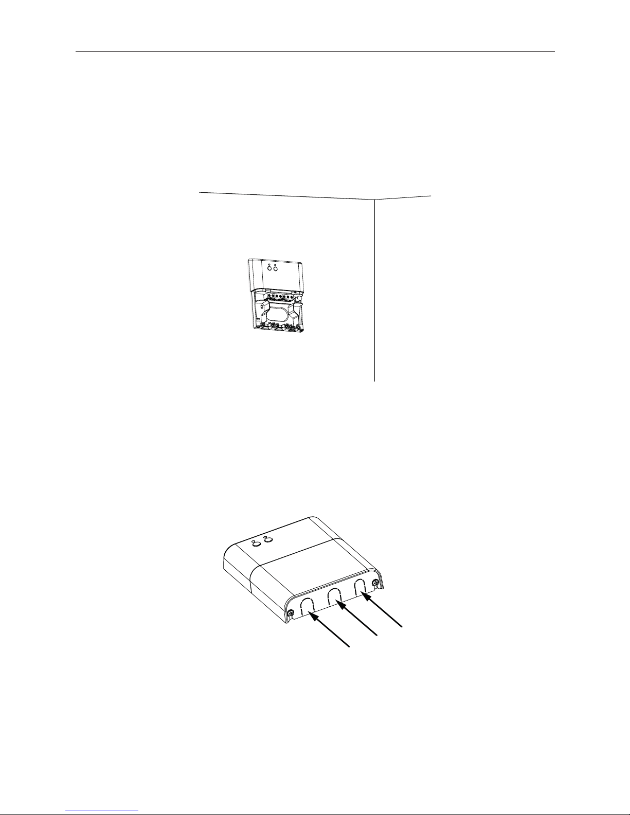
5.1.1
mountIng on a Pattress boX
Before installation, disconnect the mains voltage!
• Remove the existing programmer device from the pattress
box. Disconnect the existing cables of the programmer.
• Remove the existing backplate (if present).
• Remove the cover (E) from the MAX! Boiler Controller.
Page 9

9
Installation
• Remove the cut-out for cables (M) and pass the cables
through the cut-out hole.
Central
heating
Hot
water
• Fix the MAX! Boiler Controller to the pattress box.
• Connect the power supply.
Page 10

10
Installation
• Connect the cables of the central heating and hot water
tank to the terminals as described in the wiring diagram
in sec. “5.2 Wiring diagram“.
• Re-attach the cover.
• After finishing installation, switch the mains voltage on
again.
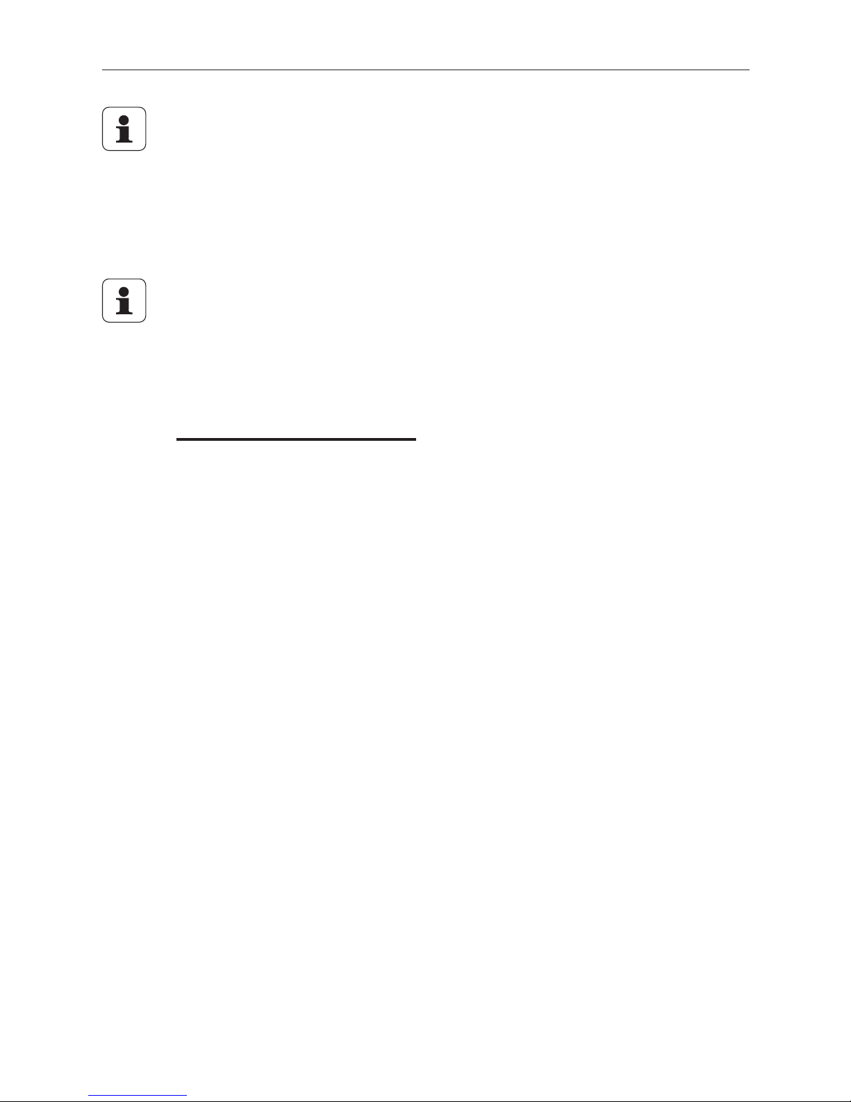
5.1.2
mountIng on the wall
You should fit the device close to the pattress box of your
central heating.
Before installation, disconnect the mains voltage!
Make sure that electrical lines in the wall will not be
damaged.
• Remove the existing programmer device.
• Remove the existing backplate (if present).
• Remove the cover (E) from the MAX! Boiler Controller.
• Mark the bore holes with a distance of 7.8 cm on the wall.
• Drill the two marked bore holes with a 5mm drill and in-
Page 11
11
Installation
sert the plugs supplied.
• Turn the screws into the plugs so that they protrude from
the wall by approx. 1.5 mm.
• Mount the device on the wall. Hang it using the brackets
on the back behind the screw heads.
• Pass the cables through the strain relief clamps.
• Connect the cables of the central heating and hot water
tank to the terminals as described in the wiring diagram
in sec. “5.2 Wiring diagram“.
• Remove the cut-outs of the strain relief on the cover.
• Re-attach the cover to the device.
• After finishing installation, switch the mains voltage on
again.
Page 12

12
Installation
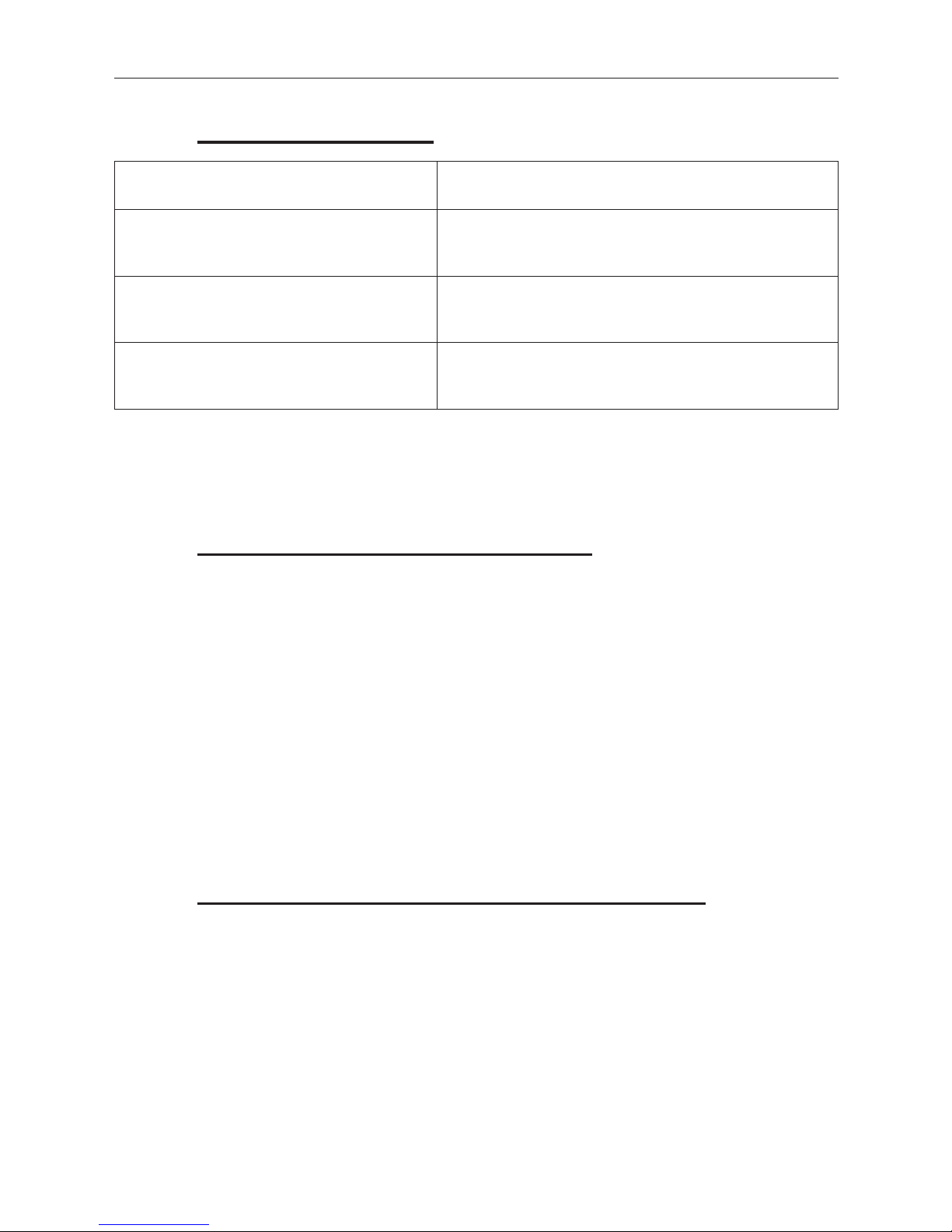
5.2
wIrIng DIagram
Permitted wire cross-section:
Rigid wire [mm2] Flexible wire with end sleeve [mm2]
0.75 - 4.0 mm
2
0.75 - 2.5 mm
2
Rigid wires must be in accordance with H05VV-F or
H05RR-F.
The following picture shows an installation example.
Please consider your individual system setup.
Page 13

13
Installation
N Neutral wire for power supply
L Live wire for power supply
Relay 1
(central heating)
L
↑
Live wire for central heating switch
1
↓
Call for heat to the boiler
Relay 2
(hot water)
2
↓
Normally open hot water terminal
1
↓
Normally closed hot water terminal
L
↑
Live wire for the hot water switch
Page 14

14
Teaching-in
6
teachIng-In
In order to integrate the MAX! Boiler Controller into a MAX!
system it has to be connected to the MAX! Cube via the MAX!
software first. All settings and programming (e.g. week programs) can be done via the MAX! software afterwards.
You have to teach-in the two channels (MAX! Central heating
and MAX! Hot water) separately.
• Start the local MAX! software and click on “New device”.
• Press and hold down the first channel button (B) of the
MAX! Boiler Controller for at least 3 seconds to activate
teach-in mode. The channel LED will start flashing green.
1.
2.
> 3 s
• The first channel will appear in the software.
• Press and hold down the second channel button (D) of the
MAX! Boiler Controller to activate teach-in mode of the
second channel.
• The second channel will appear in the software as well.
• Click on “Next” in the software to give the device a name
and assign it to a room.
• The MAX! Boiler Controller is now integrated into the
system and can be configured for each room via the MAX!
software or the smartphone app.
Page 15
15
Manual operation
In the MAX! software, you need to create one separate
room for the channel “Central heating” and one for the
channel “Hot water”. The channel “Central heating” can
also be used in rooms that include a MAX! Wall Thermostat+ already.
If you want to use your system without a MAX! Cube, you
can also directly teach-in the channel “Central heating”
to the MAX! Wall Thermostat+.
7
manual oPeratIon
With the channel buttons B or D, the single channels can be
switched on and off directly on the device. If the device is operated in connection with a MAX! Cube or MAX! Wall Thermostat, the set comfort or eco temperature will be applied.
Manual operation of “Central heating” channel:
• Press the channel button B shortly.
The central heating is switched on until the next time the current week program changes.
Manual operation of “Hot water” channel:
• Press the corresponding channel button D shortly.
This activates the Boost function: the hot water tank will be
switched on for 60 minutes.
By the end of the Boost phase, the channels automatically
change back to the prior operating mode.
Page 16
16
Response to power recovery
You can also activate the Boost function via the MAX!
Wall Thermostat+. Simply press the Boost button to
activate the function.
8
resPonse to Power recovery
After power recovery, the device starts with both channels in
MANU Off mode (regardless of the previously set mode).
As soon as the MAX! Boiler Controller receives time information from the MAX! Cube or Wall Thermostat, the channels
switch into AUTO mode (only if a Cube or Wall Thermostat has
been taught-in to the corresponding channel).
If any action is carried out by the user, e.g. operation/configuration of mode, setpoint temperature, week program, profile
settings etc., the channel switches into AUTO mode as well.
9
restore factory settIngs
The factory settings of the MAX! Boiler Controller can be restored manually. Restoring the factory settings deletes all
settings and information about taught-in devices.
First delete the device from the MAX! software.
• Press and hold down both channel buttons (B and D) si-
multaneously for at least 10 seconds.
• Release the buttons. The channel LEDs first go off and
then start flashing 4 times shortly.
• The factory settings will be restored.
Page 17
17
Error messages
10
error messages
Error code Meaning
1x long, 2x short flashing Device defective
Fast flashing Teach-in mode active
Permanent light The corresponding channel is
switched on.
11
maIntenance anD cleanIng
The product does not require any maintenance. Enlist the help
of an expert to carry out any repairs. Clean the product using
a soft, lint-free cloth that is clean and dry. You may dampen the cloth a little with lukewarm water in order to remove
more stubborn marks. Do not use any detergents containing
solvents, as they could corrode the plastic housing and label.
12
InformatIon about raDIo oPeratIon
Radio transmission is performed on a non-exclusive transmission path, which means that there is a possibility of interference occurring. Interference can also be caused by
switching operations, electrical motors or defective electrical
devices.
Page 18

18
Technical specifications
The range of transmission within buildings can differ
greatly from that available in the open air. Besides the
transmitting power and the reception characteristics of
the receiver, environmental factors such as humidity in
the vicinity have an important role to play, as do on-site
structural/screening conditions.
eQ-3 AG hereby declares that this device complies with the
essential requirements and other relevant regulations of Directive 1999/5/EC. You can find the full declaration of conformity at www.eQ-3.de.
13
technIcal sPecIfIcatIons
Device short name: BC-TS-Sw2-WM
Supply voltage: 230 V/50 Hz
Current consumption:
Channel 1: 16 A max.
Channel 2: 5 A max.
Standby power consumption: < 0.2 W
Degree of protection: IP20
Ambient temperature: 5 to 35°C
Dimensions (W x H x D): 98 x 130 x 23 mm
Radio frequency: 868.3 MHz
Receiver category: SRD category 2
Typ. open area RF range: > 100 m
Duty Cycle: < 1% pro h
Weight: 160 g
Page 19

19
Technical specifications
Max. switching capacity:
Channel 1:
ohmic load, max. 3680 W
relay: NO contact
Channel 2: ohmic load, max. 1150 W
inductive load, max. 230 VA
relay: CO
Kind of cable and
cross-section: rigid cable, 0.75 – 4 mm²
flexible cable without ferrule,
0.75 – 2.5 mm²
Installation: fixed installation, wall mounting
Method of operation: Type 1.B
Degree of pollution: 2
Subject to technical changes.
Do not dispose of the device with regular domestic
waste!
Electronic equipment must be disposed of at local collection points for waste electronic equipment in compliance with the Waste Electrical and Electronic Equipment Directive.
The CE sign is a free trading sign addressed exclusively
to the authorities and does not include any warranty of
any properties.
For technical support, please contact your specialist
dealer.
Page 20
Bevollmächtigter des Herstellers:
Manufacturer’s authorised representative:
eQ-3 AG
Maiburger Straße 29
26789 Leer / GERMANY
www.eQ-3.de
 Loading...