

Page 1
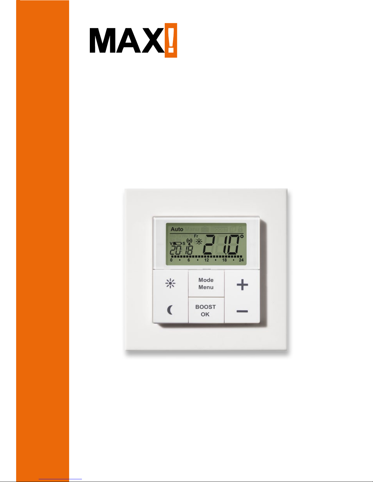
Wall Thermostat
+
BC-TC-C-WM-4
Operating manual
Page 2

2
Scope of delivery
Quantity
Item
1x MAX! Wall Thermostat
+
1x Clip-on frame
2x Plug
6x Screws
2x Adhesive stripes
2x 1.5 V LR03/micro/AAA batteries
3x Brief instruction in German/English, French/
Dutch and Polish/Italian
Scope of delivery
Page 3

3
Table of contents
Table of contents
1 Information about this manual .............................4
2 Safety instructions .................................................4
3 Function .................................................................5
4 Device overview .....................................................7
5 Start-up .................................................................9
6 Setting date and time (dAt)..................................11
7 Mounting ..............................................................12
8 Mounting in existing switches .............................15
9 Teaching-in ..........................................................16
10 Teaching-out wireless components (UnL) ..........18
11 Operating Modes .................................................19
12 Child safeguard/operating lock ...........................20
13 Setting heat pause (ON) ......................................20
14 Setting frost protection (OFF) ..............................21
15 Configuration menu .............................................21
16 Restore factory settings (rES) .............................32
17 Error messages ...................................................34
18 Maintenance and cleaning ..................................34
19 Information about radio operation ......................35
20 Technical specifications ......................................36
1st English edition 07/2014
Documentation © 2014 eQ-3 AG, Germany
All rights reserved.
Translation of the original version in German.
Version 1.1
Page 4
4
Information about this manual
1
InformatIon about thIs manual
Read this manual carefully before starting to use the device. Keep the manual so you can refer to it at a later date
if you need to. If you hand over the device to other persons
for use, please hand over the operating manual as well.
Symbols used:
Attention!
This indicates a hazard.
Note.
This section contains important additional information.
2
safety InstructIons
The device is not a toy; do not allow children to
play with it. Do not leave packaging material lying
around, as it can be dangerous in the hands of a
child.
Do not open the device: it does not contain any
components that need to be serviced by the user.
In the event of an error, please return the device
to the service department.
The device may only be operated indoors and must
be protected from the effects of damp and dust,
as well as solar or heat radiation.
Page 5
5
Function
Using the device for any purpose other than that
described in this operating manual does not fall
within the scope of intended use and shall invalidate any warranty or liability. This also applies
to any conversion or modification work. The device is intended for private use only.
3
functIon
The MAX! Wall Thermostat+ is responsible for regulating
the room temperature within the MAX! system. With the
MAX! Wall Thermostat+ up to 8 MAX! Radiator Thermostats can be comfortably regulated in a room.
The MAX! Wall Thermostat+ has an internal sensor that
measures the temperature in the room and cyclically
transmits it to the radiator thermostats.
Communication between the MAX! components is bidirectional. This ensures that the information sent reaches the recipient.
The configuration of the MAX! Wall Thermostat+ is made
according to the system variant used. You have the possibility to choose between the following two variants:
Page 6
6
Function
MAX! House solution
This is the solution for the entire house. With
a MAX! Cube, all settings of connected devices
in the house can comfortably be made via the
MAX! software.
By using the MAX! Cube, several MAX! Radiator solutions and MAX! Room solutions can be
connected to a MAX! House solution in a new
installation.
MAX! Room solution
In the room solution, the settings of all connected
devices in your room can comfortably be made via
the MAX! Wall Thermostat+. Up to 8 MAX! Radiator Thermostats+ and 8 MAX! Window Sensors
can be connected and controlled via the MAX!
Wall Thermostat+.
With a MAX! Cube, the solution can be extended
to a House solution.
Page 7
7
Device overview
4
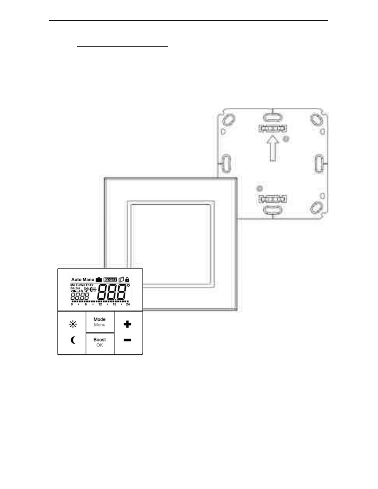
DevIce overvIew
(A) Mounting plate
(B) Clip-on frame
(C) Electronic unit/push-button
A
B
C
Page 8
8
Device overview
D
G
H
K
L
M
F
E
I
J
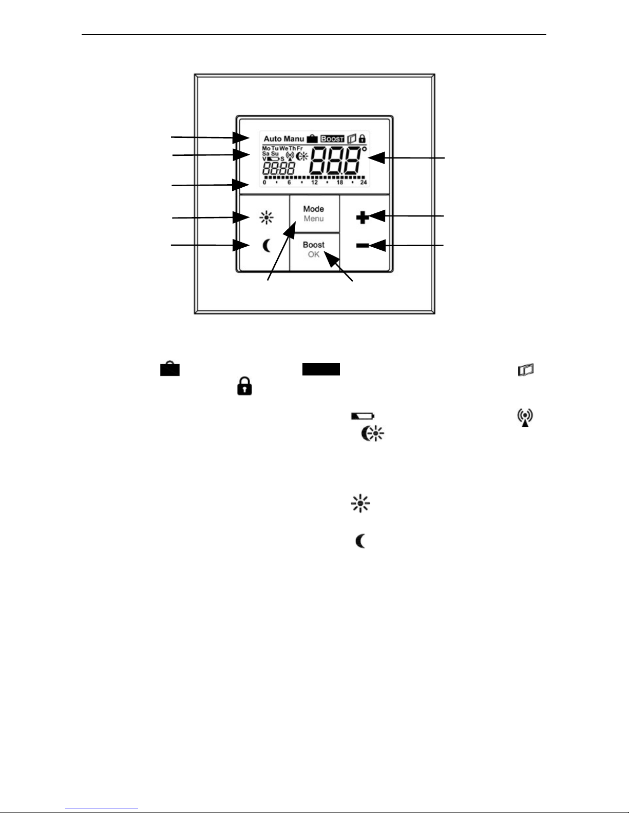
(D)
Automatic mode (Auto), manual mode (Manu), holiday function ( ), boost function (
BOOST
), open-window function ( )
,
operating lock ( )
(E)
Weekday, empty battery symbol ( ), radio sychronicity ( )
,
comfort/reduction temperature ( ), time/date
(F) Bar chart of the programmed heating phases of the cur-
rent day
(G)
Comfort temperature button (
): switching to comfort
temperature
(H)
Reduction temperature button (
): switching to reduction
temperature
(I) Mode/Menu button: change the operating mode and open
the configuration menu; exit/back in the menu
(J) Boost/OK button: confirm settings and activate the boost
function
(K) (-) button: reduce the septpoint temperature, browse in
the menu
(L) (+) button: increase the septpoint temperature, browse
in the menu
(M) Setpoint/actual temperature
Page 9

9
Start-up
5
start-up
5.1
InsertIng (replacIng) batterIes
As-delivered condition
When you are starting up the device for the first time,
first remove the mounting plate (A) on the rear of the
MAX! Wall Thermostat+.
• Hold the MAX! Wall Thermostat+ firmly in one hand
and pull off the mounting plate at one corner.
Mounted condition
Once mounted, the MAX! Wall Thermostat+ can easily
be pulled off the mounting plate and out of the frame.
• Pull sideways at the frame to remove the MAX! Wall
Thermostat+ of the wall together with the frame.
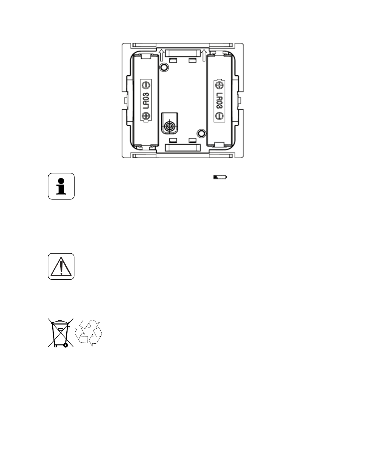
Replacing batteries
• Turn the MAX! Wall Thermostat+ over to remove or
insert the batteries.
• After removing the old batteries, please wait approx.
60 seconds.
• Insert two LR03/micro/batteries in the battery compartments (making sure that you insert them the
right way round).
• Put the MAX! Wall Thermostat+ back into the frame (B).
Page 10
10
Start-up
The empty battery symbol ( ) indicates that the
batteries need to be changed. If, in addition, a "V"
or "S" are displayed, the batteries of a taught-in
Radiator Thermostat (V) or Window Sensor (S)
have to be replaced.
Never recharge standard batteries. Do not throw
the batteries into a fire. Do not expose batteries
to excessive heat. Do not short-circuit batteries.
Doing so will present a risk of explosion.
Used batteries should not be disposed of with
regular domestic waste! Instead, take them
to your local battery disposal point.
Page 11

11
Setting date and time (dAt)
6
Setting date and time
(dAt)
After inserting or replacing batteries the firmware version number will be shown briefly. Accordingly, date and
time will be requested automatically. Settings can be
changed with the (+) and (-) buttons and confirmed with
the Boost/OK button.
• Set the year, month and date and confirm each setting with the Boost/OK button.
Year: Month and day:
• Set the time and confirm your settings with the Boost/
OK button.
Hours: Minutes:
Once the time and date were entered, the MAX! Wall
Thermostat+ changes back to normal operating mode.
If the MAX! Wall Thermostat+ was taught-in to the
MAX! Cube, the current date and time will be
transferred automatically.
Page 12
12
Mounting
During operation without Cube date and time can
be changed at any time via "dAt" in the configuration menu (see sec. „6 Setting date and time (dAt)“
on page 11).
7
mounting
You can either use screws or adhesive strips to mount
the MAX! Wall Thermostat+ to a wall in the frame supplied or integrate it into an existing switch (see sec. „8
Mounting in existing switches“ on page 15).
Adhesive strip mounting:
• Choose a site for installation. The surface on which
you are mounting the push button must be clean, dry
and greaseless.
• For mounting of the assembled MAX! Wall Thermostat+, attach the adhesive strips to the back side of the
mounting plate (A). You should be able to read the letters on the back side (according to figure).
Page 13

13
Mounting
<PA66>
• Remove the protective film from the adhesive strips.
• Press the assembled MAX! Wall Thermostat+ with the
back side to the wall in the position where it should
subsequently be attached.
Screw mounting:
• Choose a site for installation.
Make sure that no electricity or similar lines run
in the wall at this location.
• Position the mounting plate on the desired site on the
wall. Make sure that the arrow on the mounting plate
is pointing upwards.
• Use a pen to mark the positions of 2 bore holes(1) (diagonally opposite) in the mounting plate on the wall.
The bore holes (2) can be used for installation with a
flush-mounting box.
Page 14

14
Mounting
1
1
2
2
• Now drill the bore holes. If you are working with a
stone wall, drill the marked two 5 mm holes and insert
the plugs supplied. If you are working with a wooden
wall, you can pre-drill 1.5 mm holes to make screws
easier to insert.
• Use the screws and plugs supplied to fasten the mounting plate to the wall.
• Attach the MAX! Wall Thermostat+ with the frame on
the mounting plate. Make sure that the arrows on the
back side of the wall thermostat point upwards and
that the clips on the mounting plate latch into the
openings on the wall thermostat.
Page 15

15
Mounting in existing switches
8
mounting in exiSting SwitcheS
You can mount the MAX! Wall Thermostat+ with the attachment frame provided or use it with frames of other
manufacturers as well as integrate the electronic unit
into a multi-gang frame. In both cases, mounting with
adhesive strips and screws is possible. For mounting
with multiple combinations, make sure that the mounting plate of the MAX! Wall Thermostat+ is seamlessly
aligned to the already fixed mounting plate/retaining ring.
The MAX! Wall Thermostat+ is designed to fit into frames
supplied by the following manufacturers:
Manufacturer
Frame
Berker S.1, B.1, B.3, B.7 glass
ELSO Joy
GIRA
System 55
, Standard 55, E2, E22, Event, Esprit
merten 1-M, Atelier-M, M-Smart, M-Arc, M-Star, M-Plan
JUNG A 500, AS 500, A plus, A creation
Page 16

16
Teaching-in
9
teaching-in
In order to use the MAX! Wall Thermostat+ in your installation, you must teach it in to the MAX! system. The
teach-in procedure depends on the system variant used.
Choose your system variant (House or Room solution)
and follow the instructions below.
MAX! House solution
In the MAX! House solution all settings and programming (e.g. week programs) can be made via
the MAX! software.
• Start the local MAX! software and click on "New device".
• Press and hold down the Boost/OK button of the MAX!
Wall Thermostat+ for at least 3 seconds to activate
teach-in mode.
1.
2.
> 3 s
• The antenna symbol appears in the display and the
MAX! Wall Thermostat+ appears in the MAX! software.
• Click on "Next" in the software to give the device a
name and assign it to a room.
• The MAX! Wall Thermostat+ is now integrated into
Page 17

17
Teaching-in
the system and can be configured for each room via
the MAX! software.
As soon as the MAX! Wall Thermostat+ has been
taught-in to the MAX! Cube, all data such as date,
time or week program are transmitted to it via radio connection.
If you want to add a MAX! Cube to your system subsequently, a factory reset must be performed for
all devices (incl. MAX! Wall Thermostat+) prior to
teaching-in to a MAX! Cube. All settings including
your weekly profiles are deleted in this process.
MAX! Room solution
In the MAX! Room solution, you can control up to 8
MAX! Radiator Thermostats+ and 8 MAX! Window
Sensors via the MAX! Wall Thermostat+. For this
purpose teach-in the devices directly to the MAX!
Wall Thermostat+. These then take over the settings of the MAX! Wall Thermostat+ (e.g. mode,
temperature, week program).
To teach in, proceed as follows:
• Put the device to be taught-in (e.g. MAX! Radiator
Thermostat+) into teach-in mode (according to the
corresponding operating manual).
• Press and hold down the Boost/OK button of the MAX!
Wall Thermostat+ for at least 3 seconds to activate
teach-in mode.
Page 18

18
Teaching-out wireless components (UnL)
2.
> 3 s
• The antenna symbol ( ) and the remaining teach-in
time (30 seconds) will be displayed.
• If teach-in has been successful, the MAX! Wall Thermostat+ will change back to normal operating mode.
10
teaching-out wireleSS componentS
(UnL)
In the MAX! House solution, teaching-out of the
MAX! Wall Thermostat+ will be made via the MAX!
software.
In the MAX! Room solution, use the function "UnL"
in the menu to teach-out devices that are taughtin to the MAX! Wall Thermostat+ (e.g. MAX! Radiator Thermostat+). All radio components are
taught-out simultaneously.
Page 19

19
Operating Modes
To teach-out devices, proceed as follows:
• Press and hold down the Mode/Menu button for more
than three seconds.
• Select the “UnL” menu item with the (+) and (-) buttons.
• Confirm your selection using the Boost/OK button.
• "ACC" (accept) appears on the display. Confirm the
teach-out procedure using the Boost/OK button.
• All connected devices have now been taught-out from
the MAX! Wall Thermostat+.
11
operating modeS
You can choose between the operating modes auto, manu
and holiday function:
Auto: Week program – automatic temperature control
according to configured week program.
Manu: Manual operation – the temperature is set manually with the (+) and (-) buttons.
Holiday function ( ): Setting a temperature, which has
to be maintained until a fixed point in time.
Boost (
BOOST
): Setting the boost function
In the MAX! House solution you can configure the
settings for the MAX! Wall Thermostat+ via the
MAX! software.
Page 20

20
Child safeguard/operating lock
In the MAX! Room solution you can change between the functions by pressing the mode button
shortly.
If the operating mode is changed on one device in
a room, this change is applied on all radiator thermostats assigned to that room.
12
child Safeguard/operating lock
Operation of the MAX! Wall Thermostat+ can be locked to
prevent settings being changed inadvertently (if somebody
touches the thermostat accidentally, for example).
• To activate/deactivate the operating lock, briefly
press the Mode/Menu and the Boost/OK button simultaneously.
• Once activated, the operating lock symbol ( ) is shown
on the display.
13
Setting heat pauSe (on)
Battery life can be prolonged by switching the heating off
in summer. To achieve this, the valves are opened fully.
The calcification protection continues to run.
• In manual operation (Manu) press the (+) button until
“ON” is shown on the display.
• Exit manual operation (Manu) or press the (-) button
Page 21

21
Setting frost protection (OFF)
until the desired temperature is set.
14
Setting froSt protection (off)
If the room does not need to be heated, the valve can be
closed. The valve is only opened if there is a risk of frost.
The calcification protection function continues to run. To
activate this, proceed as follows:
• In manual mode (Manu), press the (-) button until
“OFF” appears on the display.
• To finish, exit manual operation (Manu) or press the
(+) button.
15
configuration menu
If you use the MAX! Wall Thermostat+ in a MAX!
House solution, you can conveniently set the functions described in the following chapters via the
MAX! software for each room.
The following steps explain how these functions
are set in the MAX! Room solution. In connection
with the MAX! Cube, these functions are deactivated at the MAX! Wall Thermostat+.
When using the device within the MAX! Room solutions,
the settings can be made in the configuration menu. The
menu can be called up by pressing the Mode/Menu button
Page 22

22
Configuration menu
of the MAX! Wall Thermostat+ for more than 3 seconds.
The menu items are selected with the (+) and (-) button
and confirmed with the OK button. If you press the Mode/
Menu button once more, this takes you back to the previous level. The menu closes automatically after 60 seconds of inactivity. The following settings can be made:
Menu
item
Meaning
dAt:
Change time and date (see sec. „6 Setting date and
time (dAt)“ on page 11)
UnL:
Teach-out wireless components (UnL) (see sec. „10
Teaching-out wireless components (UnL)“ on page 18)
Pro:
Set week program (see sec. „15.1 Setting the week
program (Pro)“ on page 23)
t-d:
Switch time and date display (see sec. „15.2 Switching
time/date display (t-d)“ on page 26)
Set comfort and reduction temperature (see sec. „15.4
Set comfort and reduction temperature“ on page 27)
S-A:
Change display of setpoint and actual temperature (see
sec. „15.3 Switching setpoint and actual temperature
display (S-A)“ on page 27)
bOS:
Set valve opening and length of “Boost” function
(see sec. „15.5 Set boost function (
BOOST
, bOS)“ on
page 28)
Setting the holiday function (see sec. „15.6 Setting the
holiday function ( )“ on page 30)
dEC:
Set valve protection function (see sec. „15.7 Setting
routine descaling (dEC)“ on page 31)
Page 23

23
Configuration menu
AEr:
Set open-window temperature for automatic temperature decrease during ventilation (see sec. „15.8
Set open-window function ( , AEr)“ on page 31)
tOF:
Set temperature offset (see sec. „15.9 Setting offset
temperature (tOF)“ on page 32)
rES:
Restoring the factory settings (see sec. „16 Restore
factory settings (rES)“ on page 32)
15.1
settIng the week program
(Pro)
In the week program, for each weekday up to 6 heating
phases (13 change settings) can be set separately. The
programming is carried out for the days chosen, whereby
temperature settings have to be set for the entire period
between 00:00 and 23:59.
• Press the Mode/Menu button for at least 3 seconds.
The display will show “Pro”.
• Confirm with the Boost/OK button. “dAy” appears
on the display.
• You can use the (+) and (-) buttons to select a single day
of the week, all weekdays, the weekend, or the entire
week (weekdays has been selected in the example).
• Confirm your selection using the Boost/OK button.
• Now set the end time of the first time period (exam-
ple: 6:00 h for the period 0:00 – 6:00 h) with the (+)
and (-) buttons.
• Confirm your selection using the Boost/OK button.
• With the (+) and (-) buttons select the chosen tem-
perature for the previously chosen time period (example: 17.0°C).
Page 24

24
Configuration menu
• Confirm your selection using the Boost/OK button.
• Repeat this procedure until temperatures are stored
for the entire period between 0:00 and 23:59 h.
In Auto mode the selected week program will be automatically adopted by all taught-in MAX! Radiator Thermostats. The temperature can be changed at any time
with the (+) and (-) buttons or comfort ( ) and reduction
temperature ( ) buttons. The modified temperature will
then remain the same until the next point at which the
program changes.
Week program: Examples
For each day of the week up to 6 heating phases (13
change settings) with individual temperature settings
can be saved with the MAX! Wall Thermostat+. The factory settings are as follows:
Page 25

25
Configuration menu
Monday-Friday:
from 00:00 to 06:00 h 17.0 °C
from 06:00 to 09:00 h 21.0 °C
from 09:00 to 17:00 h 17.0 °C
from 17:00 to 23:00 h 21.0 °C
from 23:00 to 23:59 h 17.0 °C
The display will show bars for those heating phases
where the set temperature for the period is higher than
the saved reduction temperature.
If a room (e.g. the bathroom) is also to be heated at midday, the programming can appear as follows:
Monday to Sunday:
from 00:00 to 06:00 h 15.0 °C
from 06:00 to 09:00 h 23.0 °C
from 09:00 to 12:00 h 17.0 °C
from 12:00 to 14:00 h 20.0 °C
from 14:00 to 18:00 h 17.0 °C
from 18:00 to 22:00 h 21.0 °C
from 22:00 to 23:59 h 15.0 °C
Page 26

26
Configuration menu
15.2
swItchIng tIme/Date DIsplay
(t-d)
The factory setting will show the time on the display. In
the menu the display can be switched to the date.
• Open the configuration menu by pressing the Mode/
Menu button for more than 3 seconds.
• Select the “t-d” menu item with the (+) and (-) buttons
and confirm with the Boost/OK button.
• Now set the format you want to show on the display
(date and time will switch on the display) with the (+)
and (-) buttons.
• Confirm your selection using the Boost/OK button.
Page 27

27
Configuration menu
15.3
swItchIng setpoInt anD actual temperature DIs
-
play (s-a)
The factory setting will show the setpoint temperature
on the display. In the menu the display can be switched
to the actual temperature.
• Open the configuration menu by pressing the Mode/
Menu button for more than 3 seconds.
• Select the “S-A” menu item with the (+) and (-) buttons
and confirm with the Boost/OK button.
• Set the format you want to show on the display („SEt“
for the setpoint temperature and „ACt“ for the actual
temperature) with the (+) and (-) buttons.
• Confirm with the Boost/OK button.
If the actual temperature is selected, the display will
show „SEt“ for 5 seconds on change of the setpoint temperature (or on change of mode). Afterwards, the display automatically changes back to actual temperature.
15.4
set comfort anD reDuctIon temperature
The comfort ( ) and reduction ( ) temperature button
makes switching between comfort and reduction temperature simple and user friendly. The factory setting
for the comfort temperature is 21.0 °C and the reduction
temperature 17.0 °C.
When using MAX! without Cube, the comfort and reduction temperature can be changed via corresponding buttons as follows:
Page 28

28
Configuration menu
• Press and hold down the comfort temperature button
( ) to adjust the comfort temperature or press and
hold to the reduction temperature button ( ) to adjust the reduction temperature.
• The display shows the symbol and the corresponding
comfort/reduction temperature.
• Change the temperature with the (+) and (-) buttons.
• Confirm with the Boost/OK button.
Even in auto mode, the temperature can be changed at
any time using the buttons. The adjustment will then
remain the same until the next point at which the program changes.
15.5
set boost functIon (
BOOST
, bOS)
The boost function makes use of human sensations of
heat. The heating of a room usually takes longer than
5 minutes, but the heat given off by the radiator can
be felt immediately. When the function is activated, the
heating valve opens immediately for 5 minutes at 80%
(factory setting).
• Shortly press the Boost/OK button to activate the
Boost function.
• Once the boost time has elapsed, the radiator thermostat switches back to the mode that was active
previously (Auto/Manu), with the temperature that
was set previously.
• The boost function can be deactivated prematurely
at any time by pressing the Boost/OK button again.
Page 29

29
Configuration menu
The remaining time for the function is counted down in
seconds (e.g. "300" to "000") and
BOOST
is displayed.
The duration and valve opening of the boost function can
individually be adjusted:
• Press the Mode/Menu button for at least 3 seconds.
• Select the “bOS” menu item with the (+) and (-) buttons.
• Confirm your selection using the Boost/OK button.
• Use the (+) and (-) buttons to set the duration of the
boost function from 0 to 60 min. (0, 5, 10, 15, 20, 25,
30, 60 min.). The value 0 will deactivate this function.
• Confirm your selection using the Boost/OK button.
• Set the valve opening between 0 and 100% in 5% in-
crements with the (+) and (-) buttons. The larger the
valve opening, the higher will be the heat emitted by
the radiator.
• Confirm your selection using the Boost/OK button.
If a long boost duration and a large valve opening
have been set the radiator can get very hot. After
changing the factory setting check that the radiator is not heated excessively.
The boost function will not have an immediate effect if the radiator is covered or concealed (e.g. by
a sofa).
Page 30

30
Configuration menu
If the duration of the boost function is set so that
the display exceeds 999 seconds (e.g. via the MAX!
Cube), the display value switches from seconds
to minutes.
15.6
settIng the holIDay functIon (
)
If you want to maintain a fixed temperature for a certain
period, e.g. during your holidays or a party, the holiday
function can be used.
• Briefly press the Mode/Menu button repeatedly, until the suitcase symbol ( ) appears in the display.
• Set the time up to which the temperature is to be
maintained.
• Confirm your selection using the Boost/OK button.
• Set the end date until which you want the holiday
function to be set.
• Confirm your selection using the Boost/OK button.
• Set the temperature and confirm your settings with
the Boost/OK button. The display will flash to confirm.
The set temperature will remain until the set end time.
Afterwards, the radiator thermostat will switch back to
auto mode. Radio control commands like those from a
MAX! Window Sensor or the routine descaling run will
still be performed.
Page 31

31
Configuration menu
15.7
settIng routIne DescalIng (
dEC)
The radiator thermostats can protect against valve calcification automatically. Therefore, an automatic routine
descaling is performed once a week. The time for performing this function can individually be configured (it is
factory set to run at 12:00 on Saturdays).
• Press the Mode/Menu button for at least 3 seconds.
• Select the “dEC” menu item with the (+) and (-) buttons.
• Confirm your selection using the Boost/OK button.
• Select the weekday with the (+) and (-) buttons.
• Confirm your selection using the Boost/OK button.
• Select the time with the (+) and (-) buttons.
• Confirm your selection using the Boost/OK button.
“CAL” is displayed during descaling.
15.8
set open-wInDow functIon (
, AEr)
During ventilation, the MAX! Wall Thermostat+ automatically reduces the temperature in a room in order to save
on energy costs. Meanwhile, in this phase the display of
the MAX! Wall Thermostat+ and all taught-in devices will
show the open-window symbol ( ).
When a MAX! Window Sensor is used, the opening and
closing of a window is detected at the precise time it
occurs. Whilst the window is open, the temperature is
reduced to the factory setting of 12°C. When the MAX!
Window Sensor detects the closing of the window, all
MAX! Radiator Thermostats installed in the room are
immediately reset to their original mode.
Page 32

32
Restore factory settings (rES)
• Press the Mode/Menu button for at least 3 seconds.
• Select the “AEr” menu item with the (+) and (-) buttons.
• Confirm your selection using the Boost/OK button.
• Change the temperature with the (+) and (-) buttons.
• Confirm your selection using the Boost/OK button.
15.9
settIng offset temperature (
tOF)
As the temperature is measured on the MAX! Wall Thermostat+, the temperature distribution can vary throughout a room. To adjust this, a temperature
offset of ±3.5
°C can be set. If a nominal temperature
of e.g. 20 °C is
set but the room presents with only 18 °C,an offset of
-2.0 °C needs to be set.
• Press the Menu button longer than 3 seconds.
• Select the “tOF” menu item with the (+) and (-) buttons.
• Confirm your selection using the Boost/OK button.
• Use the (+) and (-) buttons to set the temperature you
want to maintain during ventilation.
• Confirm your selection using the Boost/OK button.
16
restore factory settIngs (
rES)
The factory settings of the MAX! Wall Thermostat+ can
be restored manually, e.g. if you want to teach-in a Room
solution to a MAX! Cube or to re-install an incorrectly operating system. Restoring the factory settings deletes all
settings and information about taught-in devices.
Page 33

33
Restore factory settings (rES)
In the MAX! House solution (operation with MAX!
Cube) first delete the device from the software.
In the MAX! Room solution (operation without MAX!
Cube) the factory settings of the MAX! Wall Thermostat+ can be restored as follows:
• Press the Mode/Menu button for at least 3 seconds.
• Select the “rES” menu item with the (+) and (-) buttons.
• Confirm your selection using the Boost/OK button.
• "ACC" will be displayed. Confirm the factory reset with
the Boost/OK button.
If the MAX! Wall Thermostat+ has already been
taught-in to a MAX! Cube, the configuration menu
of the device will be locked.
You can still restore the factory settings as follows:
• Remove a battery and wait for 60 seconds.
• Press and hold down the reduction ( ), OK and the
(-) button simultaneously and insert the battery at
the same time.
• When "rES" appears on the display, the reset was performed and the buttons can be released.
Page 34

34
Error messages
17
error messages
Error
codes
Problem Solution
Battery
symbol
(
)
Battery voltage
too low
Replace batteries
F4 MAX! Cube already
taught-in
Make sure the device is
no longer taught-in to the
Cube (in the software) and
perform a reset. Then you
can teach-in the device
again.
F5 Temperature sen-
sor defective
Replace device
Slowly
flashing
antenna
symbol (
)
Connection to
taught-in MAX!
components lost
Check the power supply and the batteries of
taught-in MAX! components
Quickly
flashing
antenna
symbol (
)
Duty cycle limit
reached
The device can resume
radio communication after a waiting time of approx. one hour
18
maIntenance anD cleanIng
The product does not require any maintenance.
Enlist the help of an expert to carry out any repairs. Clean the product using a soft, lint-free cloth
that is clean and dry. You may dampen the cloth a
little with lukewarm water in order to remove more
Page 35

35
Information about radio operation
stubborn marks. Do not use any detergents containing
solvents, as they could corrode the plastic housing and
label.
19
InformatIon about raDIo operatIon
Radio transmission is performed on a non-exclusive
transmission path, which means that there is a possibility of interference occurring. Interference can also
be caused by switching operations, electrical motors or
defective electrical devices.
The range of transmission within buildings can
differ greatly from that available in the open air.
Besides the transmitting power and the reception
characteristics of the receiver, environmental factors such as humidity in the vicinity have an important role to play, as do on-site structural/
screening conditions.
eQ-3 AG hereby declares that this device complies with
the essential requirements and other relevant regulations of Directive 1999/5/EC. You can find the full declaration of conformity at www.eQ-3.de.
Page 36

36
Technical specifications
20
technIcal specIfIcatIons
Device short description: BC-TC-C-WM-4
Supply voltage: 2x 1.5 V LR03/micro/AAA
Current consumption: 30 mA (max.)
Battery life: 2 years (typ.)
Degree of protection: IP20
Ambient temperature: 5 to 50 °C
Dimensions (W x H x D): 86 x 86 x 21.5 mm
Weight: 79 g (not incl. batteries)
Radio frequency: 868.3 MHz
Receiver category: SRD category 2
Typ. open area RF range: > 100 m
Duty cycle: < 1% per h
Display: LCD
Subject to technical changes.
Page 37

37
Technical specifications
Max. number of devices to be taught-in:
MAX! House solution
• max. 50 devices in max. 10 rooms,
• max. 4 MAX! Eco Switch
• per room max. 8 MAX! Radiator Thermostats
(+)
,
8
MAX! Window Sensors
and 1 MAX! Wall Thermostat
+
MAX! Room solution:
• max. 1 MAX! Wall Thermostat+
• max. 8 MAX! Radiator Thermostats
(+)
• max. 8 MAX! Window Sensors
Page 38

38
Technical specifications
Do not dispose of the device with regular
domestic waste.
Electronic equipment must be disposed of at
local collection points for waste electronic
equipment in compliance with the Waste
Electrical and Electronic Equipment Directive.
The CE sign is a free trading sign addressed exclusively to the authorities and does not include
any warranty of any properties.
For technical support, please contact your specialist dealer.
Page 39

39
Page 40

40
Bevollmächtigter des Herstellers:
Manufacturer’s authorised representative:
eQ-3 AG
Maiburger Straße 29
26789 Leer / GERMANY
www.eQ-3.de
 Loading...