

Page 1

Window Sensor
BC-SC-Rd-WM-2
Operating manual
Page 2

2
Scope of delivery
Quantity
Item
1x MAX! Window Sensor
(electronic and magnet unit)
2x Cap (white/brown)
6x Spacers
2x Adhesive stripes
6x Screws
2x 1.5 V LR03/micro/AAA batteries
3x Brief instruction in German/English, French/
Dutch and Polish/Italian
Scope of delivery
Page 3

3
Table of contents
Table of contents
1 Information about this manual .............................4
2 Safety instructions .................................................4
3 Function .................................................................5
4 Device overview .....................................................7
5 Start-up .................................................................8
6 Teaching-in ..........................................................15
7 Restore factory settings ......................................18
8 Flashing sequences and transmission behaviour . 19
9 Maintenance and cleaning ..................................19
10 Information about radio operation ......................20
11 Technical specifications ......................................21
Documentation © 2014 eQ-3 AG, Deutschland
All rights reserved.
Translation of the original version in German.
Version 1.1 (11/2016)
Page 4
4
Information about this manual
1
InformatIon about thIs manual
Read this manual carefully before starting to use the device. Keep the manual so you can refer to it at a later date
if you need to. If you hand over the device to other persons
for use, please hand over the operating manual as well.
Symbols used:
Attention!
This indicates a hazard.
Note.
This section contains important additional information.
2
safety InstructIons
The device is not a toy; do not allow children to
play with it. Do not leave packaging material lying
around, as it can be dangerous in the hands of a
child.
Do not open the device: it does not contain any
components that need to be serviced by the user.
In the event of an error, please return the device
to the service department.
The device may only be operated indoors and must
be protected from the effects of damp and dust,
as well as solar or heat radiation.
Page 5

5
Function
Using the device for any purpose other than that
described in this operating manual does not fall
within the scope of intended use and shall invalidate any warranty or liability. This also applies
to any conversion or modification work. The device is intended for private use only.
3
functIon
The MAX! Window Sensor signals when windows or
doors are opened and closed. To save energy, the device
ensures that MAX! Radiator Thermostats automatically
reduce the temperature when a window or door is open
and increase it again when the window or door is closed.
The reduction temperature can be set separately for each
room via the MAX! software.
The MAX! Window Sensor can be used in the following solutions:
MAX! House Solution
This is the solution for the entire house. With a
MAX! Cube, all settings of connected devices in
the house can comfortably be made via the MAX!
software. By using the MAX! Cube, several MAX!
Radiator solutions and MAX! Room solutions can
be connected to a MAX! House solution in a new
installation.
Page 6

6
Function
MAX! Room solution
In the room solution, the settings of all connected
devices in your room can comfortably be made via
the MAX! Wall Thermostat+. Up to 8 MAX! Radiator
Thermostats+ and 8 MAX! Window Sensors can be
connected and controlled via the MAX! Wall Thermostat+. With a MAX! Cube, the solution can be
extended to a House solution.
MAX! Radiator solution
With the MAX! Radiator solution you can easily
start using the MAX! system. The ambient temperature within a room can be flexibly controlled
and regulated with up to 2 MAX! Radiator Thermostats+ and 3 MAX! Window Sensors. Configuration is performed directly on the MAX! Radiator
Thermostat+.
With a MAX! Wall Thermostat+, the solution can
be extended to a room solution, with a MAX! Cube
it can be extended to a House solution.
Page 7
7
Device overview
4
DevIce overvIew
The MAX! Window Sensor (A+B) consists of a large elec-
tronic unit (A) and a small magnet (B):
B
A
A+B
The device is supplied with spacers and caps in white
and brown.
C
D
(C) Teach-in button
(D) Device LED
Page 8

8
Start-up
5
start-up
5.1
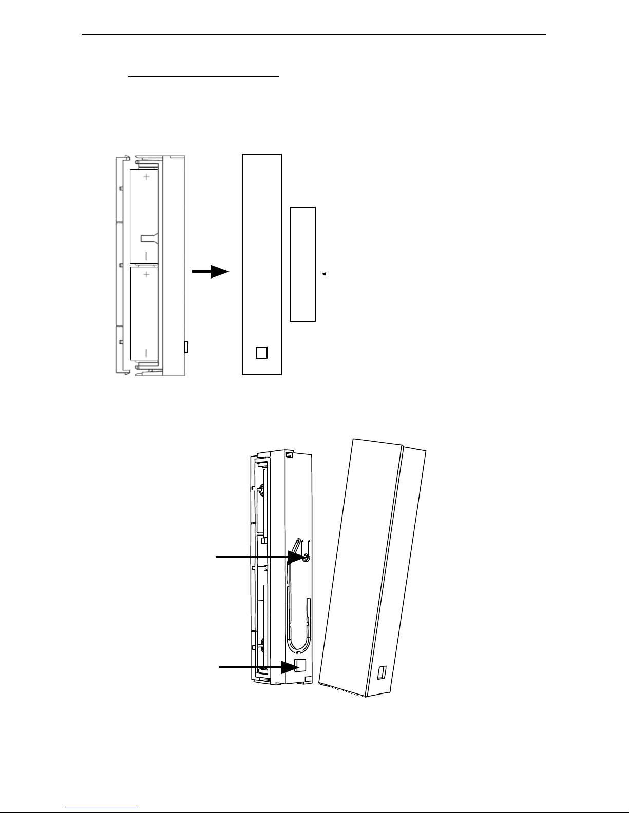
InsertIng (replacIng) batterIes
The MAX! Window Sensor is operated with two LR03/
micro/AAA batteries.
• Remove the cap of the electronic unit (A) by pulling
it forward and off the device (1). To release the cap,
squeeze it gently from above and below with your
thumb and index finger (2).
• Carefully lift the release clip (3) from the side.
Page 9

9
Start-up
3
• Pull the electronic unit (A) forward (4) and off the
bracket.
• After removing the old batteries, please wait approx.
60 seconds.
• Insert two new LR03/micro/AAA batteries in the battery compartment (making sure that you insert them
the right way round).
• Place the electronic unit (A) back onto the bracket,
allowing it to latch into place.
• Put the cap back to the electronic unit (A). Make sure
that the LED opening on the cover is positioned over
the LED (D) on the electronic unit.
Never recharge standard batteries. Do not throw
the batteries into a fire. Do not expose batteries
to excessive heat. Do not short-circuit batteries.
Doing so will present a risk of explosion.
Page 10

10
Start-up
Used batteries should not be disposed of with
regular domestic waste! Instead, take them
to your local battery disposal point.
5.2
mountIng
The MAX! Window Sensor consists of two elements: an
electronic unit (A) and a magnet (B) (see sec. „4 Device
overview“ on page 7). The electronic unit (A) must be
mounted on the frame and the magnet (B) on the window.
• First select the window that is frequently used for
ventilation and which the MAX! Window Sensor is to
be attached to.
• The magnet (B) can be mounted on either side of the
electronic unit (A). Installation must be in parallel with
a maximum spacing of 8 mm.
• The magnet (B) must be centre-aligned with the electronic unit (A).
Page 11

11
Start-up
A
B
max. 8 mm
The magnet (B) and electronic unit (A) must be attached
at the same level (or as close to the same level as possible) within the designated area. You might need to
use the spacers supplied for the magnets (B) to do this.
A
B
Page 12

12
Start-up
The window sensor can be attached either vertically or horizontally and can be positioned on the
side or at the top/bottom of the window.
Each of the elements can be fastened in two ways:
Adhesive strip mounting:
The surface on which you are mounting the element must be clean and free of grease.
• Stick the adhesive strips supplied on the back of the
electronic unit (A) and on the back of the bracket for
the magnet (B).
A
B
• Then press the electronic unit (A) and the bracket onto
the frame and window.
Page 13

13
Start-up
Screw mounting:
Screw fastening damages the window frame. For
those living in rented accommodation, this could
lead to a landlord making claim for compensation
or holding back a tenant’s deposit.
• Use a pen to mark the bore hole positions (E) of the
electronic unit (A) and the magnet holder (B) on the
window frame and casement.
E
E
E
E
A
B
• If you are working with a hard surface, you should
pre-drill the holes marked (E) using a 1.5 mm drill.
• Use the countersunk head screws supplied to fasten the
wall brackets for the electronic unit (A) and magnet (B).
Page 14

14
Start-up
If you are using the 14.5 mm high spacer, you must
first fasten it with two 2.2 x 16 mm screws and
then attach the magnet unit (B) to it with another
two screws. The flatter spacers are simply fastened together with the magnet using two 2.2 x
16 mm screws.
• Once you have fastened the wall bracket for the magnet (B), insert the magnet.
• Then place the cap on the magnet.
• Once you have fastened the wall bracket for the electronic unit (A), attach the electronic unit.
Teach-in the MAX! Window Sensor before placing
the cap on the electronic unit (A) (see sec. „6
Teaching-in“ on page 15).
• After teaching-in the MAX! Window Sensor, complete
the mounting procedure by placing the cap on the
electronic unit (A). White and brown caps are supplied with the device.
Page 15

15
Teaching-in
6
teachIng-In
In order to be able to use the MAX! Window Sensor in
your installation, you must teach it in to your system first.
You can use the MAX! Window Sensor in connection with
the MAX! Cube (House solution) as well as without MAX!
Cube (Room and Radiator solution).
6.1
teachIng-In vIa maX! cube (house solutIon)
In the MAX! House solution all settings and configurations can be made via the MAX! software. To
teach-in the device to the MAX! Cube, proceed as
follows:
• Put the MAX! Cube into teach-in mode. Start the local
MAX! software and click on "New device".
Page 16

16
Teaching-in
• To activate teach-in mode of the MAX! Window Sensor, press and hold down the teach-in button (C) on
the electronic unit (A) for at least 3 s. The device LED
starts to flash.
2.
> 3 s
• Click on "Next" in the software to give the device a
name and assign it to a room.
• Successful teaching-in of the MAX! Window Sensor is
confirmed by the LED lighting up once.
• Place the cap on the electronic unit (A).
6.2
teachIng-In wIthout cube (room/raDIator so
-
lutIon)
You can teach-in the MAX! Window Sensor directly to the
MAX! Wall Thermostat+ (Room solution) or the MAX! Radiator Thermostat+ (Radiator solution).
• Put the device to be taught-in (e.g. MAX! Wall Thermostat+) into teach-in mode (according to the corre-
Page 17

17
Teaching-in
sponding operating manual).
• To activate teach-in mode of the MAX! Window Sensor, press and hold down the teach-in button (C) on
the electronic unit (A) for at least 3 s. The device LED
starts to flash.
2.
> 3 s
• Successful teaching-in of the MAX! Window Sensor is
confirmed by the LED lighting up once.
• Place the cap on the electronic unit (A).
To initialise the window sensor, once open and
close the window to which the MAX! Window Sensor is mounted.
The window sensor can be taught-in to one MAX!
Cube or one MAX! Wall Thermostat+/MAX! Radiator Thermostat+ only.
Page 18

18
Restore factory settings
7
restore factory settIngs
The factory settings of the MAX! Window Sensor can be
restored manually. Restoring the factory settings deletes
all settings and information about taught-in devices.
Before restoring the factory settings of the MAX!
Window Sensor, first delete the device from the
MAX! software in case you use it in connection with
a MAX! Cube.
• First remove the batteries from the electronic unit (A).
• Wait 60 seconds.
• Hold down the teach-in button (C) and at the same
time re-insert the batteries.
• Press and hold down the teach-in button (C) until the
LED (D) starts to flash.
• Release the teach-in button (C); the factory settings
are restored.
Page 19

19
Flashing sequences and transmission behaviour
8
flashIng sequences anD transmIssIon behavIour
The LED’s flashing sequences have different meanings:
Flashing sequence
Meaning
1x flash Window open/closed, radio command sent
successfully
2x flashes DutyCycle limit reached. The device will com-
municate again after max. one hour.
3x flashes Error message: wireless command not sent
successfully
9
maIntenance anD cleanIng
The product does not require any maintenance.
Enlist the help of an expert to carry out any repairs.
Clean the product using a soft, lint-free cloth that
is clean and dry. You may dampen the cloth a little
with lukewarm water in order to remove more
stubborn marks. Do not use any detergents containing solvents, as they could corrode the plastic
housing and label.
Page 20

20
Information about radio operation
10
InformatIon about raDIo operatIon
Radio transmission is performed on a non-exclusive
transmission path, which means that there is a possibility of interference occurring. Interference can also
be caused by switching operations, electrical motors or
defective electrical devices.
The range of transmission within buildings can
differ greatly from that available in the open air.
Besides the transmitting power and the reception
characteristics of the receiver, environmental factors such as humidity in the vicinity have an important role to play, as do on-site structural/
screening conditions.
eQ-3 Entwicklung GmbH hereby declares that this device
complies with the essential requirements and other relevant regulations of Directive 1999/5/EC. You can find the
full declaration of conformity at www.eQ-3.de.
Page 21

21
Technical specifications
11
technIcal specIfIcatIons
Device short description: BC-SC-Rd-WM-2
Supply voltage:
2x 1.5 V LR03/micro/AAA
Current consumption: 50 mA (max.)
Battery life: 5 years (typ.)
Degree of protection: IP20
Ambient temperature: 0 to 50 °C
Dimensions (W x H x D):
Electronic unit: 18.5 x 103.5 x 24.5 mm
Magnet: 12 x 48 x 12 mm
Weight: 52 g (incl. battery)
Radio frequency: 868.3 MHz
Receiver category: SRD category 2
Typ. open area RF range: > 100 m
Duty cycle: < 1 % per h
Subject to technical changes.
Page 22

22
Technical specifications
Do not dispose of the device with regular
domestic waste.
Electronic equipment must be disposed of at
local collection points for waste electronic
equipment in compliance with the Waste
Electrical and Electronic Equipment Directive.
The CE sign is a free trading sign addressed exclusively to the authorities and does not include
any warranty of any properties.
For technical support, please contact your specialist dealer.
Page 23

23
Page 24

24
Bevollmächtigter des Herstellers:
Manufacturer’s authorised representative:
eQ-3 AG
Maiburger Straße 29
26789 Leer / GERMANY
www.eQ-3.de
 Loading...