

Page 1
INSTRUCTION MANUAL
MODE D'EMPLOI
MANUAL DE INSTRUCCIONES
BEDIENUNGSANLEITUNG
MANUALE D'USO
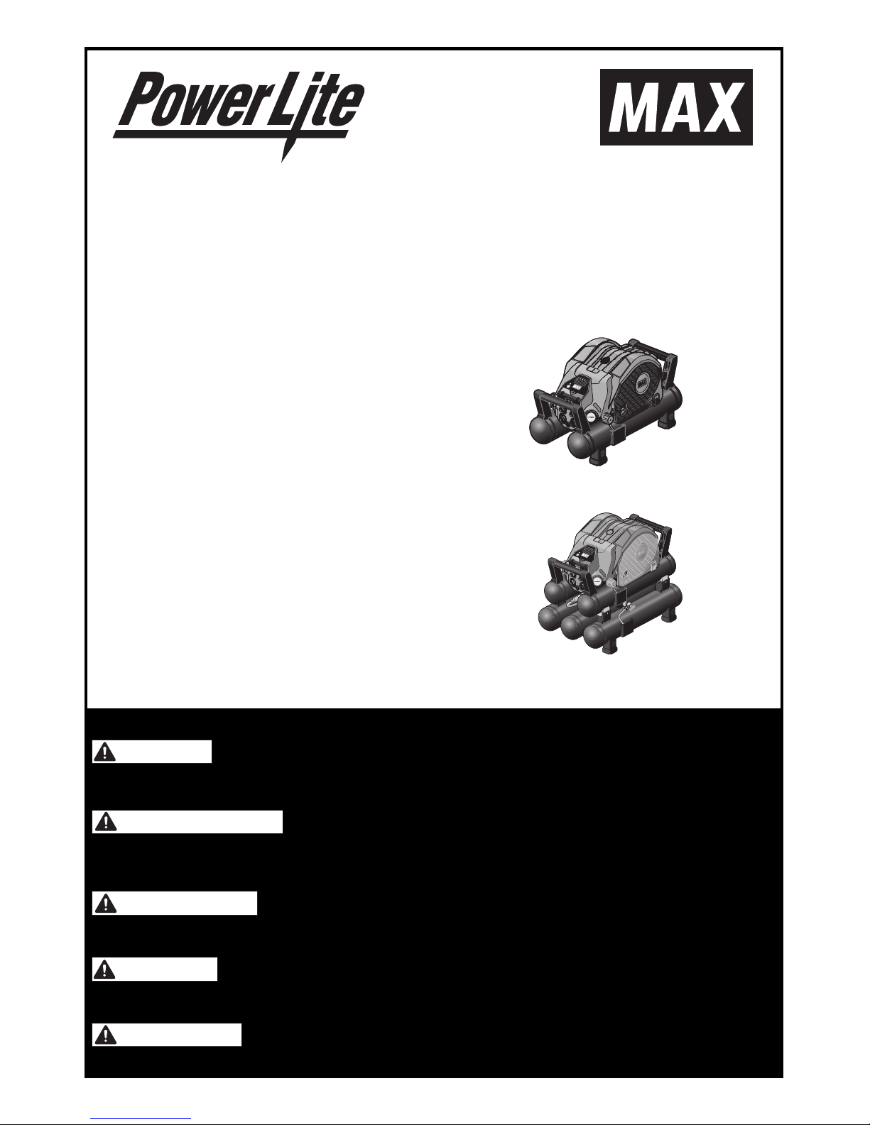
HIGH PRESSURE COMPRESSOR
COMPRESSEUR À HAUTE PRESSION
COMPRESOR DE ALTA PRESIÓN
HOCHDRUCK-KOMPRESSOR
COMPRESSORE AD ALTA PRESSIONE
INDEX ENGLISH Page 7 to 22
INDEX FRANÇAIS Pages 23 à 39
ÍNDICE ESPAÑOL Página 40 a 56
INHALTSVERZEICHNIS DEUTSCH Seite 57 bis 73
INDICE ITALIANO Pagina 74 a 90
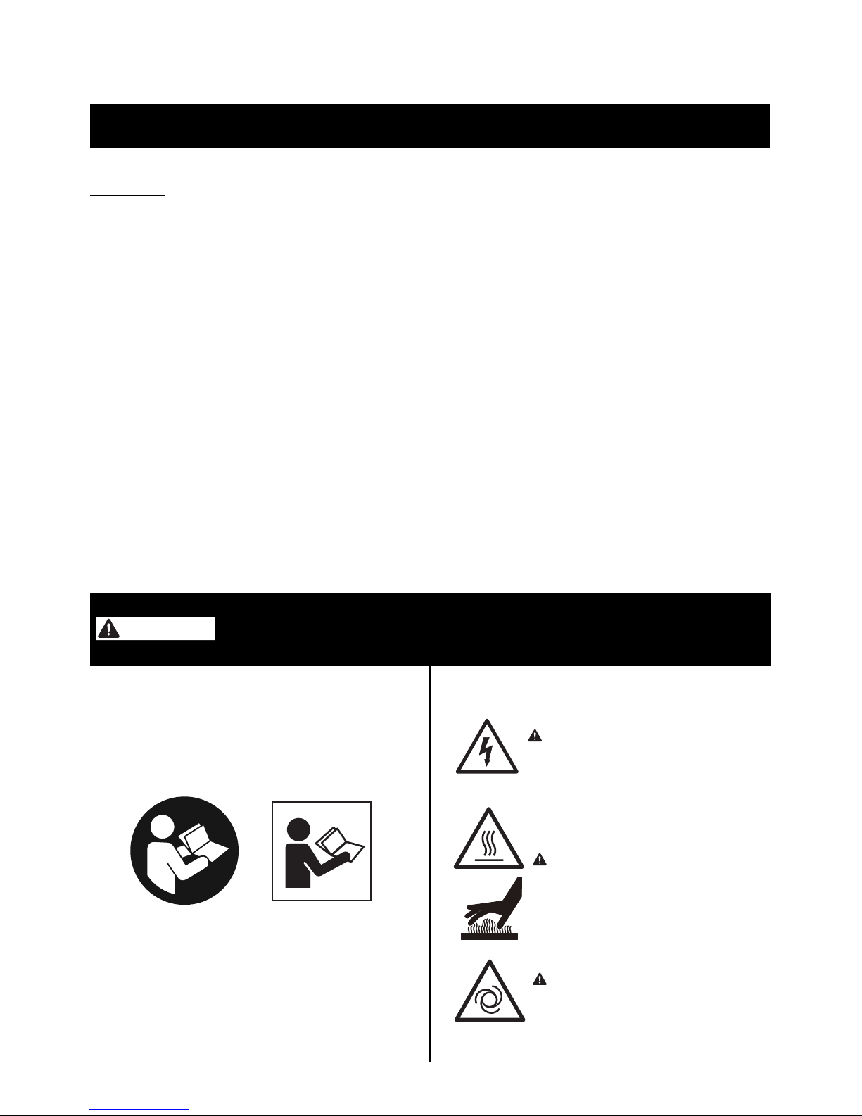
BEFORE USING THIS COMPRESSOR, STUDY THIS MANUAL TO ENSURE SAFETY
WARNING AND INSTRUCTIONS. KEEP THESE INSTRUCTIONS WITH THE TOOL FOR
FUTURE REFERENCE.
AVANT D'UTILISER CE COMPRESSEUR, LIRE CE MANUEL ET LES CONSIGNES DE
SÉCURITÉ AFIN DE GARANTIR UN FONCTIONNEMENT SÛR. CONSERVER CE
MANUEL EN LIEU SÛR AVEC L'OUTIL AFIN DE POUVOIR LE CONSULTER
ULTERIEUREMENT.
ANTES DE UTILIZAR ESTE COMPRESOR, LEA DETENIDAMENTE LAS INSTRUCCIONES Y ADVERTENCIAS DE SEGURIDAD. GUARDE ESTAS INSTRUCCIONES CON LA
HERRAMIENTA PARA UNA POSIBLE CONSULTA FUTURA.
LESEN SIE VOR INBETRIEBNAHME DES GERÄTES DIE GEBRAUCHS- UND SICHERHEITSHINWEISE. BEWAHREN SIE DIESE GEBRAUCHS- UND SICHERHEITSHINWEISE
FÜR EINE SPÄTERE EINSICHTNAHME AUF.
PRIMA DI UTILIZZARE QUESTO COMPRESSORE, STUDIARE IL MANUALE PER APPRENDERNE LE AVVERTENZE E LE ISTRUZIONI DI SICUREZZA. TENERE QUESTE ISTRUZIONI INSIEME AL COMPRESSORE PER CONSULTAZIONI FUTURE.
WARNING
AVERTISSEMENT
ADVERTENCIA
WARNUNG
ATTENZIONE
AKHL1260E
AKHL1260EX
Page 2

2
DEFINITIONS OF SIGNAL WORDS
WARNING: Indicates a potentially hazardous situation which, if not avoided, could result in death
or serious injury.
CAUTION: Indicates a potentially hazardous situation which, if not avoided, may result in minor
or moderate injury.
NOTE: Emphasizes essential information.
DEFINITIONS DES INDICATEURS PRINCIPAUX
AVERTISSEMENT: Indique une situation potentiellement à risque qui, si elle n’est pas évitée, peut résulter
en un danger mortel ou une blessure grave.
ATTENTION: Indique une situation potentiellement à risque qui, si elle n’est pas évitée, peut résulter
en une blessure mineure ou modérée.
REMARQUE: Accentue les informations essentielles.
DEFINICIÓNES DE LOS INDICADORES PRINCIPALES
ADVERTENCIA: Indica una situación potencialmente peligrosa que, si no se evita, puede resultar en
muerte o lesiones graves.
PRECAUCIÓN: Indica una situación potencialmente peligrosa, que si no se evita, puede resultar en
una herida menor o moderada.
NOTA: Destaca las informaciones esenciales.
DEFINITIONEN DER MARKIERTEN HINWEISE
WARNUNG: Weist auf eine möglicherweise gefährliche Situation hin, die wenn sie nicht vermieden
wird, zu Unfällen mit schweren Verletzungen oder Todesfolge führen kann.
VORSICHT: Weist auf eine möglicherweise gefährliche Situation hin, die wenn sie nicht vermieden
wird, zu Unfällen mit Verletzungen oder Sachschäden führen kann.
HINWEIS: Hebt besonders wichtige Informationen hervor.
DEFINIZIONI DEGLI INDICATORI PRINCIPALI
ATTENZIONE: Indica una situazione potenzialmente pericolosa che, se non è evitata, può risultare in
morte oppure ferita seria.
AVVERTENZA: Indica una situazione potenzialmente pericolosa che, se non è evitata, può risultare in
ferita minore oppure moderata.
NOTA: Accentua le informazioni essenziali.
Page 3
3
Fig.A/Abb.A
2
1
5
7
8
9
b
c
0
a
d
4
3
6
h
e
f
g
Fig.B/Abb.B
j
k
l
m
i
9
Page 4
4
Fig.C/Abb.C Fig.D/Abb.D Fig.E/Abb.E
Fig.F/Abb.F Fig.G/Abb.G Fig.H/Abb.H
Fig.I/Abb.I Fig.J/Abb.J Fig.K/Abb.K
Fig.L/Abb.L
Page 5
5
Fig.M/Abb.M
Fig.N/Abb.N Fig.O/Abb.O
Fig.P/Abb.P Fig.Q/Abb.Q Fig.R/Abb.R
Fig.S/Abb.S Fig.T/Abb.T Fig.U/Abb.U
①
②
①
②
Page 6

6
Page 7
7
ORIGINAL INSTRUCTION
INDEX
1. SYMBOLS ..........................................................................7
2. SAFETY INSTRUCTIONS ..................................................8
3. SPECIFICATIONS ............................................................ 12
4. INSTRUCTIONS FOR OPERATION ................................13
5. PROTECTIVE DEVICE.....................................................19
6. ABNORMALITIES DURING OPERATION.......................19
7. BUZZER TYPES...............................................................20
8. HOW TO INSTALL OPTIONAL 1260E TANK .................21
9. AUTOMATIC ADJUSTMENT OF OPERATING POWER
(INVERTER CONTROL)...................................................21
10.IN ORDER TO MAINTAIN PERFORMANCE...................22
1. SYMBOLS
The following shows the symbols used for the
equipment and this Instruction Manual. Be sure
that you understand their meaning before use.
READ ALL SAFETY WARNINGS AND ALL INSTRUCTIONS.
Failure to follow the warnings and instructions
may result in death serious injury. Save all warnings and instructions for future reference.
RISK OF ELECTRIC SHOCK
WARNING: Before doing any
work on the compressor it must be
disconnected from the power supply.
RISK OF HIGH TEMPERATURES
CAUTION: The compressor contains some parts which might reach
high temperatures.
RISK OF ACCIDENTAL START-UP
CAUTION: The compressor could
start automatically in case of a blackout and subsequent reset.
ENGLISH
INSTRUCTION MANUAL
BEFORE USING THIS COMPRESSOR, STUDY THIS MANUAL TO ENSURE SAFETY
WARNING AND INSTRUCTIONS. KEEP THESE INSTRUCTIONS WITH THE TOOL FOR
FUTURE REFERENCE.
WARNING
Page 8

8
DO NOT USE IN THE RAIN
Using the compressor in these
or similar conditions will increase the risk of electric
shock, dangerous malfunction,
and overheating.
WEAR SAFETY GLASSES OR GOGGLES
Danger to the eyes always exists due to the possibility of dust being blown up by the exhausted
air or of a fastener flying up due to the improper
handling of the tool. For these reasons, safety
glasses or goggles shall always be worn when
operating the tool.
The employer and/or user must ensure that proper
eye protection is worn. Eye protection equipment
must conform to the requirements of the American
National Standards Institute, ANSI Z87.1 (Council
Directive 89/686/EEC of 21 DEC. 1989) and provide both frontal and side protection.
The employer is responsible to enforce the use
of eye protection equipment by the tool operator
and all other personnel in the work area.
NOTE: Non-side shielded spectacles and face
shields alone do not provide adequate protection.
EAR PROTECTION MAY BE
REQUIRED IN SOME ENVIRONMENTS
As the working condition may include exposure to high noise
levels which can lead to hearing
damage, the employer and user should ensure
that any necessary hearing protection is provided and used by the operator and others in the
work area.
WHEN DISPOSING THE MACHINE OR ITS
PARTS, FOLLOW THE RELEVANT NATIONAL
RULES.
Only for EU countries
Do not dispose of electric equipment
together with household waste material!
In observance of European Directive 2012/19/EU
on waste electrical and electronic equipment and
its implementation in accordance with national
law, electric equipment that have reached the end
of their life must be collected separately and returned to an environmentally compatible recycling
facility.
The compressors are manufactured to meet
RoHS directives.
2. SAFETY INSTRUCTIONS
PRECAUTIONS ON USING THE COMPRESSOR
IMPORTANT INFORMATION
Most accidents that result from compressor operation and maintenance are caused by the failure to observe basic safety rules or precautions.
An accident can often be avoided by recognizing
a potentially hazardous situation before it occurs,
and by observing appropriate safety procedures.
Basic safety precautions are outlines in the
"SAFETY" section of this Instruction Manual and
in the sections which contain the operation and
maintenance instructions.
Hazards that must be avoided to prevent bodily
injury or machine damage are identified by
WARNINGS on the compressor and in this
Instruction Manual.
Never use this compressor in a manner that has
not been specifically recommended by manufacturer, unless you first confirm that the planned
use will be safe for you and others.
TO AVOID SEVERE PERSONAL INJURY
OR PROPERTY DAMAGE
BEFORE USING THE TOOL, READ CAREFULLY AND UNDERSTAND THE FOLLOWING
"SAFETY INSTRUCTIONS":
FAILURE TO FOLLOW WARNINGS COULD
RESULT IN DEATH OR SERIOUS INJURY.
WARNING
Page 9

9
DEATH OR SERIOUS BODILY INJURY COULD
RESULT FROM IMPROPER OR UNSAFE USE OF
COMPRESSOR, TO AVOID THESE RISKS, FOLLOW THESE BASIC SAFETY INSTRUCTIONS.
HIGH PRESSURE COMPRESSOR PROVIDES
BOTH HIGH PRESSURE AND REGULAR PRESSURE AIR. FOR USAGE OF HIGH PRESSURE
AIR, HIGH PRESSURE COMPRESSOR IS DESIGNED ONLY FOR MAX POWERLITE NAILERS
AND POWERLITE HOSE. UNSPECIFIED USAGE
WILL CAUSE SERIOUS ACCIDENTS.
1. NEVER TOUCH MOVING PARTS
Never place your hands, fingers or body
parts near the compressor's moving parts.
2. NEVER OPERATE WITHOUT ALL
GUARDS IN PLACE
Never operate the compressor without all guards
or safety features in place and in proper working
order. If maintenance or servicing requires the
removal of a guard or safety features, be sure to
replace the guards or safety feature before resuming operation of the compressor.
3. ALWAYS WEAR EYE PROTECTION
Always wear safety goggles or equivalent eye
protection. Compressed air must never be aimed
at anyone or any part of the body. Be sure to wear
protective gear including the sound-proofing and
protective garment, crash cap and safety footwear suited for the given working environment.
4. PROTECT YOURSELF AGAINST ELECTRIC SHOCK
Prevent body contact with grounded surfaces such as pipes, radiators, ranges and refrigeration enclosures. Never operate the
compressor in damp or wet locations.
5. DISCONNECT THE COMPRESSOR
Always disconnect the compressor from the power plug and remove the compressed air from the
air tank before servicing, inspecting, maintaining,
cleaning, replacing or checking any parts.
6. AVOID UNINTENTIONAL STARTING
Do not carry the compressor while it is connected to its power source or when the air
tank is filled with compressed air. Be sure the
power switch in the "OFF" position before
connecting the compressor to its power
source.
7. STORE COMPRESSOR PROPERLY
When not in use, the compressor should be
stored in dry place. Keep out of reach of children. Lock-out the storage area.
8. KEEP WORK AREA CLEAN AND WELL LIT
Keep work area clean and well lit. Cluttered or
dark areas invite accidents.
9. KEEP CHILDREN AWAY
Do not let visitors contact compressor extension
cord. All visitors should be kept safely away from
work area. Keep out of reach of children.
10. NEVER USE THE MACHINE IN ANY
UNSTABLE PLACE
Never use it in a place where it could move or
fall of itself. Be sure to install the compressor
on a flat floor, with leg rubber underneath it;
the allowable tilt angle of the floor is up to 10
degrees. If the installation floor is tilted and
slippery, ensure that the compressor does not
move during operation. Do not use it on a
shelf or stand where it may fall or tumble.
11. DRESS PROPERLY
Do not wear loose clothing or jewelry. They
can be caught in moving parts. Wear protective hair covering to contain long hair.
12. DO NOT ABUSE POWER CORD
Never yank it to disconnect from receptacle.
Keep power cord from heat, oil and sharp edges.
13. MAINTAIN COMPRESSOR WITH CARE
Inspect cords periodically and if damaged,
have repaired by authorized service facility.
14. USE A SAFE EXTENSION CORD
In order to prevent an electric shock, use a 3core extension cord with a 3-pole earthing
plug and a 3-core earthing plug socket.
Make sure that the extension cord is in the
good working condition. If the cord is damaged, replace or repair it. The cord should
have a sufficient capacity for the current running to the product. The cord of an insufficient capacity will cause a voltage drop or an
electric power loss, resulting in overheating.
The following table shows the cord size used
depending on the cord length.
If the compressor is to be used outdoors, use
an exclusive extension cord.
Page 10

10
Tab.1 SECTION VALID FOR A MAX LENGTH OF 20m (65')
Avoid electrical shock hazard. Never use this
compressor with a damaged or frayed electrical
cord or extension cord. Inspect all electrical
cords regularly. Never use in near water or in any
environment where electric shock is possible.
15. STAY ALERT
Watch what you are doing. Use common
sense. Do not operate compressor when you
are tired. Compressor should never be used by
you if you are under the influence of alcohol,
drugs or medication that makes you drowsy.
16. CHECK DAMAGED PARTS AND AIR
LEAK
Before further use of the compressor, a guard
or other part which is damaged should be carefully checked to determine that it will operate
properly and perform its intended function.
Check for alignment of moving parts, binding
of moving parts, breakage of parts, mounting, air leak, and any other conditions that
may affected its operation.
A guard or other part that is damaged should
be properly repaired or replaced by an authorized service facility unless otherwise indicated elsewhere in this Instruction Manual.
Have defective pressure controllers replaced by authorized service facility.
Do not use compressor if switch does not
turn it on and off.
17. OPERATE COMPRESSOR CORRECTLY
Operate the compressor according to the instructions provided herein. Never allow the
compressor to be operated by children, individuals unfamiliar with its operation or unauthorized personal.
18. KEEP ALL SCREWS, BOLTS AND COVERS TIGHTLY IN PLACE
Keep all screws, bolts, and plates tightly
mounted.
Check their conditions periodically.
19. KEEP HANDLES DRY, CLEAN AND FREE
FROM OIL AND GREASE
Slippery handles do not allow for safe handling
of the compressor in unexpected situations.
20. KEEP MOTOR AIR VENT CLEAN
The motor air vent must be kept clean so that
air can freely flow at all times. Check for dust
build-up frequently.
21. OPERATE COMPRESSOR AT THE RATED VOLTAGE
Operate the compressor at voltages specified on their nameplates. If using the compressor at a higher voltage than the rated
voltage, it will result in abnormally fast motor
revolution and may damage the unit and
burn out the motor.
22. NEVER USE A COMPRESSOR WHICH IS
DEFECTIVE OR OPERATING ABNORMALLY
If the compressor appears to be operating
unusually, "SERVICE REQURED" LED is lit
up, making strange noises, or otherwise appears defective, stop using it immediately
and arrange for repairs by an authorized
service facility.
23. DO NOT WIPE PLASTIC PARTS WITH
SOLVENT
Solvent such as gasoline, thinner, benzine,
carbon tetrachloride, and alcohol may damage and crack plastic parts. Do not wipe
them with such solvents. Wipe plastic parts
with a soft cloth lightly dampened with mild
detergent and dry thoroughly.
24. USE ONLY GENUINE REPLACEMENT
PARTS
Replacement parts not original may void
your warranty and can lead to malfunction
and resulting injuries. Genuine parts are
available from your dealer.
COMPRESSOR HP kW VOLTAGE DIAMETER MAX LENGTH
AKHL1260E/EX (CE)
21.5
a.c. 230V 2.5mm 20m(65ft.)
AKHL1260E/EX (USA) a.c. 115V
#12
(American Wire Gauge)
15m(50ft.)
WARNING
Page 11

11
25. DO NOT MODIFY THE COMPRESSOR
Do not modify the compressor. Always contact the authorized service facility for any repairs. Unauthorized modification may not
only impair the compressor performance but
may also result in accident or injury to repair
personnel who do not have the required
knowledge and technical expertise to perform the repair operations correctly.
26. TURN OFF THE SWITCH WHEN THE
COMPRESSOR IS NOT USED
When the compressor is not used, turn the
switch OFF, disconnect the plug from the
power source and open the drain cock to discharge the compressed air from the air tank.
27. NEVER TOUCH THE SURFACE OF THE
HIGH-TEMPERATURE SECTION
In order to prevent a burn, do not touch the
piping, head, cylinder, motor, tank, inverter
case and other metal parts.
28. DO NOT DIRECT AIR STREAM AT BODY
Risk of injury, do not direct compressed air at
persons or animals.
29. DRAIN TANK
Drain tank daily.
30. DO NOT STOP COMPRESSOR BY PULLING OUT THE PLUG
Use the "POWER" switch.
31. WHENEVER USING THE HIGH PRESSURE
SIDE OF THE MAX POWERLITE COMPRESSOR, THE GENUINE PARTS FOR THE MAX
POWERLITE TOOLS, POWERLITE HOSE
MUST BE USED.
32. NEVER USE A TRANSFORMER FOR THE
POWER SUPPLY OF THIS COMPRESSOR.
USING A TRANSFORMER TO INCREASE THE
VOLTAGE WILL CAUSE A FAILURE OR
BURNOUT. (IF A TRANSFORMER IS USED,
OPERATION OF THE MACHINE WILL STOP.)
33. NEVER CONNECT THE COMPRESSOR
TO AN ENGINE GENERATOR OR DIRECT-CURRENT POWER SUPPLY
The compressor will break or be damaged
from burning.
34. THIS COMPRESSOR IS FOR INDOOR
USE. DO NOT INSTALL THE COMPRESSOR IN ANY PLACE EXPOSED TO RAIN
OR SPLASHED WATER, HIGH-HUMIDITY
PLACE OR HIGH-TEMPERATURE PLACE
If used in the wet condition, it could produce
an electric shock or be short-circuited, resulting in ignition. Use it under the environmental conditions provided by its specifications.
Also, do not store or use in cold environments.
35. DO NOT OPERATE THE TOOL NEAR A
FLAMMABLE SUBSTANCE
Never operate the tool near a flammable
substance (e.g., thinner, gasoline, etc.). Volatile fumes from these substances could be
drawn into the compressor and compressed
together with the air and this could result in
an explosion.
36. NEVER USE THE TOOL IN AN EXPLOSIVE ATMOSPHERE
Sparks from the tool may ignite atmospheric
gases, dust or other combustible materials.
37. BE SURE TO EARTH THE COMPRESSOR
Earth the compressor to prevent a worker
from getting an electric shock. It comes with
a 3-pole cord and a 3-pole earthing plug so
that it can be connected to an appropriate
earthing plug socket.
A green-and-yellow striped wire is an earthing conductor. Never connect it to other
charged terminals.
38. CARRY THE COMPRESSOR IN THE FOLLOWING PROPER MANNERS.
• AKHL1260E : Hold the com-
pressor grips with both
hands.
• AKHL1260EX :
Carry the compressor by having two
people hold each
side of the compressor grips.
Do not turn the compressor over or lift it with
a hook or rope.
39. TAKE CARE TO TRANSPORT THE COMPRESSOR CORRECTLY, DO NOT OVERTURN IT OR LIFT IT WITH HOOKS OR
ROPES.
Page 12

12
40. DO NOT PUT FINGERS IN THE BLEEDER
OR CLEARANCES IN THE HOUSING.
This can result in injury, electric shock or
burns.
41. DO NOT USE ANY ADAPTER PLUGS
WITH THE COMPRESSOR
The compressor is factory-equipped with a
specific electric cord and plug for connection
to a proper electric power source. Never
modify the plug in any way. Do not use any
adapter plugs with the compressor.
42. IF OPERATING THIS COMPRESSOR IN A
DAMP LOCATION IS UNAVOIDABLE, USE
A GROUND FAULT CIRCUIT INTERRUPTER (GFCI) PROTECTED SUPPLY
Use of a GFCI reduces the risk of electric
shock.
3. SPECIFICATIONS
Product No. AKHL1260E/EX(CE) AKHL1260E/EX(USA)
Dimensions
L 583mm / EX:583mm 23" / EX:23"
W 309mm / EX:380mm 12-1/8" / EX:15"
H 337mm / EX:479mm 13-1/4" / EX:18-7/8"
Weight 16.2kg / EX:23.3kg 35.4lbs / EX:51.1lbs
Power supply a.c.230V±10%
50Hz±1% Ø1
a.c.115V±10%
60Hz±1% Ø1
Rated current 6A 12A
Tank capacity 4.3lx2 / EX:4.3lx5 1.14Gal.x2 / EX:1.14Gal.x5
Motor power 2HP
Protective earthing Class1
Protective structure IP20
Working temperature 0°C to +40°C 32°F to 104°F
Working humidity 85%RH or less. No dew condensation.
Height above sea level UP to 1000m 3,281ft.
Storage temperature -10°C to +50°C 14°F to 122°F
Storage humidity 85%RH or less. No dew condensation.
Pressure switch working range
OFF: 34 bar 500 psi
ON: 30 bar 435 psi
Page 13

13
4. INSTRUCTIONS FOR OPERATION
Unpack the compressor and check for any deficiency, damage caused during transportation
and loose bolts and screws.
READ SECTION TITLED " SAFETY INSTRUCTIONS "
WEAR SAFETY GLASSES OR GOGGLES
Danger to the eyes always exists due to the possibility of dust being blown up by the exhausted air or
of a fastener flying up to the improper handling of
the tool. For these reasons, safety glasses or goggles shall always be worn when operating the tool.
The employer and/or user must ensure that proper
eye protection is worn. Eye protection equipment
must conform to the requirements of Council Directive 89/686/EEC of 21 DEC. 1989 (the American National Standards Institute. ANSI Z87.1) and
provide both frontal and side protection.
NOTE: Non-side shielded spectacles and face
shields alone do not provide adequate
protection.
NOTE: The information contained in this Instruc-
tion Manual is designed to assist you in
the safe operation and maintenance of
the compressor.
Some illustrations in this Instruction Manual may show details or attachments that
differ from those on your own compressor.
1. GROUNDING INSTRUCTIONS
1. THIS PRODUCT MUST BE GROUNDED
In the event of an electrical short circuit,
grounding reduces the risk of electric shock
by providing an escape wire for the electric
current. This product is equipped with a cord
having a grounding wire with an appropriate
grounding plug. The plug must be plugged
into an outlet that is properly installed and
grounded in accordance with all local codes
and ordinances.
2. WARNING:
IMPROPER INSTALLATION
OF THE GROUNDING PLUG IS ABLE TO
RESULT IN A RISK OF ELECTRIC SHOCK
When repair or replacement of the cord or
plug is required, do not connect the grounding wire to either power terminal. The wire
with insulation having an outer surface that is
green with or without yellow stripes is the
grounding wire.
3. CHECK WITH A QUALIFIED ELECTRICIAN
OR SERVICEMAN WHEN THE GROUNDING INSTRUCTIONS ARE NOT COMPLETELY UNDERSTOOD, OR WHEN IN
DOUBT AS TO WHETHER THE PRODUCT
IS PROPERLY GROUNDED. DO NOT MODIFY THE PLUG PROVIDED; IF IT DOES NOT
FIT THE OUTLET, HAVE THE PROPER
OUTLET INSTALLED BY A QUALIFIED
ELECTRICIAN.
4. CE MODEL IS FOR USE ON A NOMINAL
230-V CIRCUIT, AND USA MODEL IS FOR
USE ON A NOMINAL 120-V. EACH PRODUCT HAS GROUNDING PLUG. ONLY CONNECT THE PRODUCT TO AN OUTLET
HAVING THE SAME CONFIGURATION AS
THE PLUG. DO NOT USE AN ADAPTER
WITH THIS PRODUCT.
2. INSTALLATION
1. NEVER USE THE MACHINE IN A PLACE
WHERE ANY VOLATILE COMBUSTIBLE
SUBSTANCE HAS BEEN STORED.
Never use it near gasoline, thinner, gas,
paint or adhesive agent, because they could
be ignited or blow up.
2. NEVER USE THE MACHINE NEAR THE
HEAT OF FIRE OR ANY COMBUSTIBLE
SUBSTANCE.
3. DO NOT USE THE MACHINE IN A OVERLY
DUSTY(WOODEN CHIPS, ETC.) PLACE.
WARNING
Plug
Grounding Pin
Grounded
Outlets
Grounding Pin
Plug
Grounded
Outlets
WARNING
Page 14

14
4. NEVER USE THE MACHINE IN AN
UNSTABLE PLACE.
Never use it in a place where it could move
or fall of itself.
Be sure to install the compressor on a flat
floor, with leg rubber underneath it; the allowable tilt angle of the floor is up to 10 degrees. If the installation floor is tilted and
slippery, ensure that the compressor does
not move during operation. Do not use it on
a shelf or a stand where it may fall or tumble.
5. USE THE MACHINE IN THE APPROPRIATE
DIRECTION.
Install it appropriately.
6. NEVER INSTALL THE MACHINE IN THE
RAIN OR IN A PLACE SPLASHED WITH
WATER OR EXPOSED TO HIGH TEMPERATURE.
Using it in the wet condition could cause an
electric shock or a short-circuit, resulting in a
fire due to burnout or ignition.
7. AVOIDING A PLACE EXPOSED TO HIGH
TEMPERATURE OR THE DIRECT SUNSHINE, BE SURE TO USE THE MACHINE
IN THE WELL-VENTILATED SHADE.
Using it under high temperature or in the direct sunshine not only deteriorates its durability, but increases the temperature of the
main body, causing danger to your safety.
Be sure to use it in the well-ventilated shade.
The adequate room temperature is +5°C to
+30°C (41°F to 86°F). Maximum is 0°C to
+40°C (32°F to 104°F).
8. NEVER BLOCK A VENTILATION OPENING OR USE THE MACHINE IN A BOX OR
A NARROW PLACE(IN A VEHICLE, ETC.)
Neglect of this may generate abnormal heat,
causing a trouble or an accident.
Install the compressor at the distance of 1 m
or more from the wall to secure sufficient
ventilation and cooling.
9. DO NOT USE THE COMPRESSOR IN ANY
PLACE WHERE THE TEMPERATURE IS
0°C (32°F) OR LESS OR THE AMBIENT
TEMPERATURE EXCEEDS +40°C (104°F).
Page 15

15
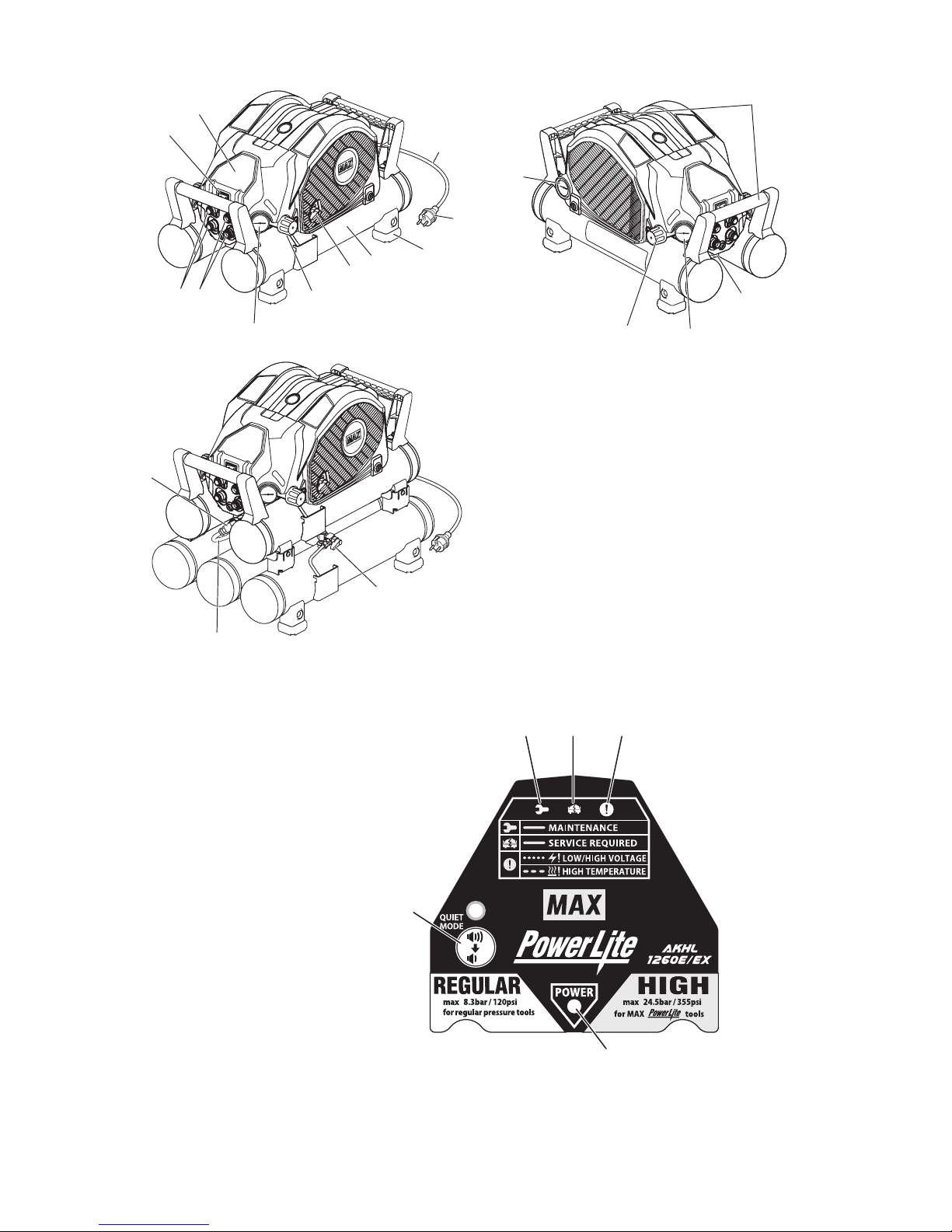
3. NAME OF PARTS (See Fig.A)
Description of Functions of Key Components
1
Power switch
Turns on or off the power supply
2
Pressure-Reduction valve adjustment handle (HIGH) (Orange cap)
Intended for exclusive use with the tool. It adjusts
the operating pressure of the tool.
3 Pressure-Reduction valve adjust-
ment handle (REGULAR) (Yellow
cap)
Adjusts the pressure supplied to the regular pressure
nailers and pneumatic tools (operating air pressure 8.3
bar (120psi) maximum).
4
Pressure gauge in the tank
Indicates pressure in the tank. The pressure increases
up to 34 bar (500psi).
5
Pressure gauge (HIGH)
It indicates the set pressure on the pressure-reduction
valves (HIGH).
(24.5 bar (335psi) maximum)
6
Pressure gauge (REGULAR)
It indicates the set pressure on the pressure-reduction
valves (REGULAR). (8.3 bar (120psi) maximum)
7
High pressure air chuck (for MAX
tools)
It connects the MAX air hose for the tools.
8
Regular pressure air chuck (for
regular pressure tools)
It connects the air hose for the regular pressure nailers.
9
Drain cock
It drains compressed air and water, Drain once when the
work is finished or more a day.
0
Power plug
It is usable with a triode ground outlet.
a
Power cord
b
Air tank
c
Rubber foot
d
Control panel
It allows switching the mode between Normal and Quiet.
(See Fig.B) For details of the LEDs and switches on the
Control panel, see "Control Panel" on page 16.
• Current consumption is reduced in the operation in
Quiet mode.
e
Grip for two-handed carry
f
Air chuck 44K
It connects the flexible pipe M-5 of lower three tanks.
g
Flexible pipe M-5
It connects the upper two tanks and the lower three tanks.
h
Stop plug
It seals the part to attach the air chuck 44K.
Page 16

16
Control Panel (See Fig.B)
i
POWER LED
j
MAINTENANCE LED
If it is lit up, send the machine to your dealer or an authorized service facility for inspection. (See page 22)
k
SERVICE REQUIRED LED
If it is lit up, it is due to a failure on the inverter or motor. Send the machine to your dealer or authorized
service facility to have their checkup or repair. (See page 20)
l
TEMPERATURE OR ELECTRICAL PROBLEM LED
See the buzzer types in Chapter 6. (See page 20)
m
QUIET MODE SWITCH
This machine also offers a power-saving operation Quiet mode that you can select when you want to
suppress the noises accompanying the operation, or when tripping of the circuit breaker is anticipated
during continuous operation. Press the Quiet mode switch to turn on this mode.
• A buzzer sounds with a beep and the LED lights up when the operation switching takes place.
• The switching is available independent of whether the compressor is in operation or stopped.
• Even when the circuit breaker tripped or you have disconnected the power plug from the outlet during
operation, status of the last operation is stored in memory.
• Even when the Quiet mode switch is pressed in a low temperature environment, the compressor continues running in the Normal mode until it reaches the OFF pressure. After the compressor is fully
warmed, it shifts to the Quiet mode the next time it is used.
Page 17

17
4. MACHINE OPERATING PROCE-
DURE
Inspection and checkup prior to operation
• Prior to use, check the bolts and nuts for
loosening and the parts for missing one.
• The power supply used must be following
specifications and be provided with a circuit breaker. Allowable source voltage
range is ±10%.
CE: a.c.230V/10A USA: a.c.115V/15A
• Diameter and length of the extension cord
or drum cord used must be the following,
respectively. And the cord must be fully
drawn out when used.
CE: Diameter 2.5mm
2
minimum / Length
20m maximum
USA: Diameter AWG12 minimum / Length
50ft. maximum
• Make sure the machine is installed in the
right direction when using it.
∗ Use the machine in compliance with the in-
structions provided in "SAFETY INSTRUCTIONS" on page 8.
∗ Pressure values in the description do not in-
clude the error in reading the pressure gauge.
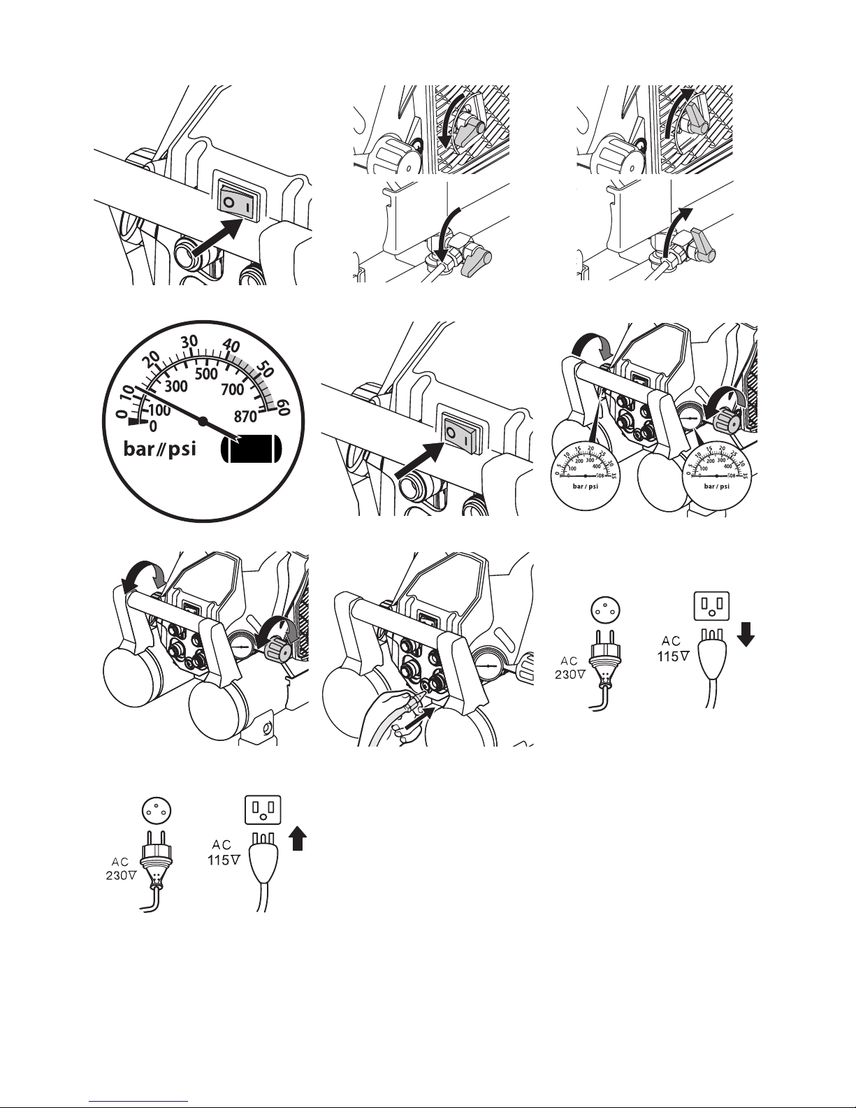
1. After turning off the machine power
switch, connect the power plug to the
outlet.
2. (Fig.C,D) Turn the power switch on while
maintaining the drain cock fully open.
The buzzer sounds with a beep at the
same time.
• For buzzer sounding patterns, see
page 20.
3. (Fig.D) Make sure that the motor starts to
run and the air is leaking from the drain
cock when the drain cock is open.
4. (Fig.E) Close the drain cock and make
sure no air is leaking from the cock.
5. Turn the adjustment handle (in 2 locations) of the pressure-reduction valve fully clockwise until you cannot move it
anymore and make sure that the above
operation moves the pressure gauge
pointer (Fig.F) at both locations.
• As the pressure in the air tank increases
due to the pressure characteristic of the
pressure-reduction valve, the pressure can
vary from the set supply pressure by as
much as 3 bar (44psi).
Turn the pressure-reduction valve's adjustment handle counterclockwise once to reduce the pressure and then proceed to the
adjustment while increasing the pressure
by turning the adjusting hand clockwise.
6. Make sure that the compression operation is automatically stopped in the following time.
• 1260E approx. 6 minutes
• 1260EX approx. 12 minutes.
Except when the power-saving operation
in Quiet mode is turned on, auxiliary tank
is connected or voltage drop occurred,
since these extends the operating hours.
7. Wait for 5 minutes after the operation is
stopped to confirm that there are no abnormal noises or air leakages and that
the compressor does not restart.
8. (Fig.D) Discharge the compressed air by
opening the drain cock somewhat. Make
sure that the operation is resumed due to
a decrease in the pressure.
9. (Fig.E,G) Close the drain cock and turn
the power off while the compression operation is turned on to make sure that
these actions stop the machine from operating.
10. (Fig.H) Turn the adjustment handle (in 2
locations) of the pressure-reduction
valve counterclockwise to make sure that
this turning moves the pressure gauge
pointer downward at both locations. (You
may hear sounds due to air leaking but it
does not mean there is a failure.)
WARNING
CAUTION
Page 18

18
11. (Fig.D) Open the drain cock to discharge
all the compressed air and water in the air
tank.
If you found any abnormalities in the checkup or inspection prior to the operation, send
the machine to your dealer or authorized
service facility for inspection or repair.
Operating Procedure
Before operating the machine, be sure to carry
out the "Inspection and checkup prior to operation" described on page 17.
1. Fully open the drain cock and turn the
power switch on. The buzzer will sound
with a beep at the same time.
• For buzzer sounding patterns, see
page 20.
After the operation has started, close the
drain cock tight to increase the pressure.
2. (Fig.I) After confirming the operation has
stopped due to the increased pressure,
turn the adjustment handle of the pressure-reduction valve to adjust the operating pressure of the nailer and pneumatic
tool to the appropriate level. When adjusting the pressure, turn the pressurereduction valve's adjustment handle
counterclockwise to set the pressure at a
level lower than the appropriate value by
2 bars once. Then proceed to the adjustment while increasing the pressure by
turning the handle clockwise.
• Make sure to start the adjustment at a level
lower than the appropriate pressure and
continue the adjustment while increasing
the pressure from that level upward. If you
start the adjustment from a level higher
than the appropriate value, an error results
between the pressure gauge value and actually used pressure. (Due to Characteristics of pressure-reduction valve
respectively)
• 2 pressure-reduction valves provided on
this machine allow you to connect MAX
and the general-purpose nailer or
pneumatic tool.
<Pressure-reduction valve H> Allows
connection and use of MAX PowerLite
tools (of operating pressure of 24.5 bars
(355psi) maximum)
<Pressure-reduction valve L> Allows connection and use of the general-purpose
nailers or pneumatic tools (of operating
pressure of 8.3 bars (120psi) maximum)
• You must observe
the specified operating
air pressure for the nailers and pneumatic
tools.
Using a nailer or pneumatic tool without adjusting the supply pressure with the reduction valve can seriously degrade their
performance, induce their premature aging
or damage them.
• Using a nailer or pneumatic tool at an inappropriate pressure level (at an unnecessary high
pressure) increases their air consumption, potentially degrading their capability in continuous work. Be sure to use them at the
appropriate pressure.
3. (Fig.J) After you have finished with the
adjustment of supply pressure, you can
start the operation by connecting the air
hose to the air outlet (air chuck).
4. Connect the high pressure hose to the
high pressure air hose for MAX PowerLite
tools to the high pressure air chuck on
the H side of the pressure-reduction
valve.
Connect the air hose for the general-purpose
nailer to the air chuck on the L side of the
pressure-reduction valve.
• The air chuck is the one-touch type, allowing you to connect the air plug to the air
chuck just by pushing in.
• Before connecting the air hose to this compressor, make sure
that the air hose and
hose fixture are firmly secured.
WARNING
WARNING
Page 19

19
5. PROTECTIVE DEVICE
If internal heat builds up during operation due to
clogging of the airflow orifice, if the machine is
used in a highly heated environment or if an abnormality occurs inside the machine, the thermal
protector for preventing burnout may be activated to stop the motor operation. The buzzer will
sound in this case. In such a case:
1. (Fig.G,K) Turn the power switch off and
disconnect the power plug from the outlet.
• For buzzer sounding patterns, see
page 20.
2. (Fig.C,L) Connect the power plug to the
outlet and turn the power switch on to
resume the operation.
• If the motor has sufficiently cooled down,
the resumed operation may active the protective device soon after. In other cases,
the operation may not resumed when you
turned the power switch on. In such a
case, wait for about 30 minutes for the motor to cool down before restarting the machine.
3. If the protective device was activated
when there were no apparent problems
existing in the operating environment,
stop using the compressor and send it to
your dealer or authorized service facility
for checkups or repairs.
6. ABNORMALITIES DURING
OPERATION
• If you detect any abnormalities, do not op-
erate the compressor.
If you encounter any of the following abnormal
phenomena, turn off the power switch immediately, disconnect the power plug from the outlet
and send the machine to your dealer or authorized service facility for checkups or repairs.
1. The following problems may occur even
when there are no problems with the
power supply or wiring: (See "PROTECTIVE DEVICE" on page 19.)
• Turning on the power switch does not start
up the machine.
• Motor moan is generated.
2. Abnormal sounds are generated during
operation. (See "AUTOMATIC ADJUSTMENT OF OPERATING POWER" (INVERTER CONTROL) on page 21.)
3. The safety valve instead of the pressure
sensor is activated, allowing the compressed air to blow out.
4. Air leakage happens.
5. Pressure does not increase. (See
page 21)
6. An electrical shock-like pain is felt when
touched the metal part.
7. Other abnormalities than the above that
is recognized during operation.
WARNING
WARNING
Page 20

20
7. BUZZER TYPES
In normal operation
In cases of abnormal operation
Buzzer sounds Symptom Actions taken
A one-time short beep sound (Pi)
At powering on When the quiet mode is switched -
LED
LAMP
Buzzer sounds
Cause
Actions taken
CE USA
1
Short
blinking
None
Power supply is
over 258V or below
195V
Power supply is
over 138V or below
90V
Examine the state of
the power supply (See
page 21)
Short beep sounds
(Pi, Pi, Pi, ...)
Power supply is excessively high or low
voltage
2
Long
blinking
Long beep sounds
(Pii, Pii, Pii, ...)
• Motor temperature went abnormally
high
• Temperature in the control circuit has
built up to an abnormally high level
• Do not use the compressor in extremely
high temperatures.
• Examine the state of
the power supply
(See page 21)
• Never block a ventilation opening or use
the machine in a box
or a narrow place (in
a vehicle, etc.)
3
Lightning
Beeping sounds
(Piiiiiii.........)
• Motor does not run
• Failure in the control circuit
It is due to a failure on
the inverter or motor.
Send the machine to
your dealer or authorized service facility to
have their checkup or
repair.
Page 21

21
8. HOW TO INSTALL OPTIONAL 1260E TANK
With AKHL1260E, you can add the optional
AKTH13 air tank for 1260EX. If more air is required, use the following steps to install the optional air tank.
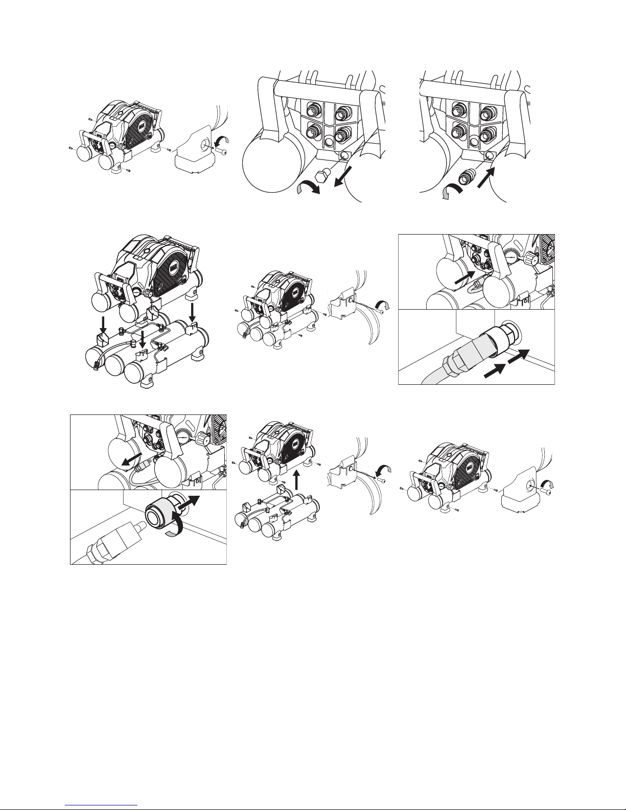
Installation
1. (Fig.G,K) Turn off the power switch of the
compressor and unplug the power cord
from the electrical outlet.
2. (Fig.D) Open the drain cock and drain
compressed air from the tank.
3. (Fig.M) Remove the four screws from the
rubber feet of the compressor.
4. (Fig.N,O) Remove the stop plug from the
compressor clockwise and mount by turning the air chuck 44K that comes with the
AKTH13 counterclockwise.
5. (Fig.P) Mount the rubber feet of the compres-
sor on the holders of the AKTH13.
6. (Fig.Q) Fasten the four screws securely
with a screwdriver.
7. (Fig.R) Connect the connector of the flexi-
ble pipe to the air chuck 44K. When connecting, please press the air plug strongly
because the pressing is in two stages.
8. (Fig.L,C) Make sure that the four screws
and the air chuck 44K are not loose, plug
the compressor’s power cord in the electric outlet and turn the compressor’s
power switch on.
9. Before operating the machine, be sure to
carry out the "Inspection and checkup
prior to operation" described on page 17.
Removal
1. (Fig.G,K) Turn off the power switch of the
compressor and unplug the power cord
from the electrical outlet.
2. (Fig.D) Open the drain cock of the com-
pressor and optional air tank and drain
compressed air from the tank.
3. (Fig.S) Disconnect the connector of the
flexible pipe from the air chuck 44K. Turn
the sleeve of the air chuck 44K counterclockwise , and push the sleeve to remove
the air plug.
4. (Fig.T) Remove the four screws of the rub-
ber feet that fasten the optional air tank to
the compressor, and remove the air tank
by lifting up the compressor.
5. (Fig.U) Fasten the four screws with a
screwdriver.
6. (Fig.L,C) Plug the compressor’s power
cord in the electric outlet and turn the
compressor’s power switch on.
7. Before operating the machine, be sure to
carry out the "Inspection and checkup
prior to operation" described on page 17.
9. AUTOMATIC ADJUSTMENT
OF OPERATING POWER (INVERTER CONTROL)
Microcomputer-based inverter control is enabled
on this machine in order to ensure the maximum
utilization of the discharging performance. Adjustment of the operating power is automatically continued until the pressure in the machine tank
reaches the maximum level. Operating sounds
may change when the operating power is
switched, but you do not have to worry about them.
Changes in the sounds are not due to a failure.
• The pressure level at which the output change-
over is activated varies depending on the capacity of the main power supply, type of
extension cord used and parallel use of other
electric equipment. If the voltage is excessively
low, extra time will be required for the filling.
• If the fill time is longer than usual or when the
pressure does not increase, change the current connection to the power supply (reconnect
to the main power supply) or stop the joint use
of the power supply with a power tool.
• When capacity of the main power is excessively
low, or when it is jointly used with another power
tool, a radical voltage drop results, may result in
startup failure.
• The circuit breaker of the power supply may be
activated if the total current consumption resulting from the parallel use with another power tool exceeds the current capacity of the
circuit breaker.
If the circuit breaker trips, the power supply
switch of the compressor moves to the OFF
position.
Stop using other power tools on the same power source as the compressor. Then, after waiting for 30 seconds or more, turn the switch ON.
Page 22

22
10.IN ORDER TO MAINTAIN
PERFORMANCE
1. Drain water from the machine.
After the work is finished, open the drain
cock gradually to drain the compressed air
and water in the air tank until the pressure
gauge in the tank points to 0.
• Not draining the water will result in the
inside of the air tank becoming moldy,
potentially leading to a failure.
2. (Fig.Bi) The Maintenance LED lights up.
Operating hours of this machine are measured with a microcomputer. The MAINTENANCE LED lights up as the machine
operating hours reaches 1000 hours. If the
Maintenance LED lights up, send the machine to your dealer or an authorized service
facility for inspection.
3. Implement the machine inspection on a
regular basis.
The User is requested to implement cleaning
and inspection of the machine in order to maintain its performance. Please do not hesitate to
let your dealer or authorized service facility inspect your machine more than once a year.
4. Handle this machine carefully.
Dropping the machine inadvertently, bumping it
against solid objects or hitting it can cause deformation, cracks or damage to the machine.
The User is advised not to invite an accident by
dropping, bumping or hitting the machine.
5. Never sit or place an object on the top of
the machine.
Neglect of this could cause a trouble or break it.
6. Inspect the machine every time you use it.
Check and inspect the machine in conformance with the procedure described in the
SAFETY INSTRUCTIONS provided on
page 8 and after.
7. ABOUT PRODUCTION YEAR AND
MONTH
This product bears production number in the
RATING LABEL. The three digits of the
number from left indicates the production
year and month.
(Example)
17408035H
Year 2017
Month April
1 January
2 February
3March
4April
5May
6 June
7July
8 August
9 September
AOctober
B November
C December
Page 23

• The content of this manual might be changed without notice for improvement.
• Le contenu de ce manuel est sujet à modification sans préavis à des fins d'amélioration.
• El contenido de este manual se puede modificar sin previo aviso para su mejora.
• Änderungen der Betriebsanleitung zum Zwecke der Verbesserung ohne Ankündigung vorbehalten.
• Il contenuto di questo manuale è soggetto a variazioni senza preavviso nell'ambito della politica di
miglioramento del prodotto.
• The specifications and design of the products in this maniual will be subject to change without ad-
vance notice due to our continuous efforts to improve the quality of our products.
• Les caractéristiques et la conception des produits mentionnés dans ce manuel sont sujettes à des
modifications sans préavis en raison de nos efforts continus pour améliorer la qualité de nos produits.
• Las especificaciones y el diseño de los productos de este manual estarán sujetos a modificación sin
previo aviso debido a nuestros continuos esfuerzos para mejorar la calidad de nuestros productos.
• Änderungen an technischen Daten und Design der Produkte in diesem Handbuch im Sinne der
Produktverbesserung bleiben ohne Ankündigung vorbehalten.
• Le specifiche e il design dei prodotti menzionati in questo manuale sono soggetti a modifiche senza
preavviso a causa dei nostri continui sforzi volti a migliorare la qualità dei nostri prodotti.
4100430
170310-00/01
PRINTED IN JAPAN IMPRIMÉ AU JAPON IMPRESO EN JAPÓN GEDRUCKT IN JAPAN STAMPATO IN GIAPPONE
Camerastraat 19
1322 BB Almere The Netherlands
Phone: +31-36-546-9669
FAX: +31-36-536-3985
6-6 NIHONBASHI HAKOZAKI-CHO,
CHUO-KU, TOKYO, JAPAN
POST CODE 103-8502
TEL: (03) 3669-8131
FAX: (03) 3669-7104
wis.max-ltd.co.jp/int/ (GLOBAL Site)
www.max-europe.com (EUROPE Site)
www.maxusacorp.com (USA Site)
257 East 2nd Street
Mineola, NY 11501, U.S.A.
TEL: 1-800-223-4293
FAX: (516)741-3272
 Loading...