

Page 1
Positive Displacement
DISCONTINUED
Flowmeters
Operational Manual
For Model:
Model 243 Only
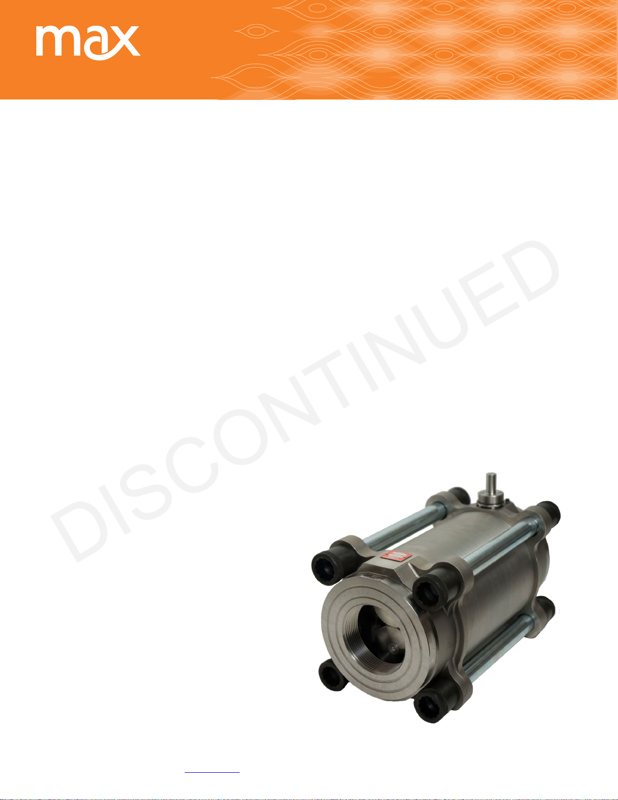
240 Helical Series
Positive Displacement Flow Meters
Max Machinery, Inc. Discontued: 243 Manual © Copyright 2014 1
Page 2

Table of Contents
DISCONTINUED
Meter General Description ...................................................page 3
Transmitter General Description ...................................... page 4
Meter Specications ..............................................................page 3
Transmitter Specications
Analog .......................................................................................page 4
Transmitter Specications
Frequency (Pulse) ...................................................................page 5
Do and Don’ts ..........................................................................page 8
Installation ...............................................................................page 6
Piping Diagrams ......................................................................page 7
ANSI FlangeANSI Flange Stud Torque ..............................page 8
Operation .................................................................................page 9
Troubleshooting .....................................................................page 12
241 Helical Flow Meter ......................................................... page 16
242 Helical Flow Meter .........................................................page 17
243 Helical Flow Meter .........................................................page 13
Contact for Repairs
& Calibration Services ......................................................... page 14
Custom Instructions for Hazardous Locations/Explosion Proof Housing:
http://www.maxmachinery.com/content/explosion-proof-installation-instructions
DO NOT ATTEMPT TO INSTALL OR START FLOW METER WITHOUT READING THIS ENTIRE MANUAL
Max Machinery, Inc. (MMI) reserves the right to make changes to the product in this Instruction Manual to improve performance, reliability, or
manufacturability. Consequently, contact MMI for the latest available specications and performance data. Although every effort has been made to
ensure accuracy of the information contained in this Instruction Manual, MMI assumes no responsibility for inadvertent errors.
Max Machinery, Inc. Discontued: 243 Manual © Copyright 2014 2
Page 3

Meter General Description
DISCONTINUED
The Max 240 Series Flow Meters are positive displacement helical rotor type units capable of precise measurements
over a wide range of ow rates and uid viscosities.
The three sizes of this series (241, 242, and 243) will measure ows from 0.1 L/min to 1400 L/min. Material viscosities
between 3 and 1,000,000 centipoise may be accommodated.
In a helical rotor type ow meter, a precise amount of the uid being measured is trapped between the rotors as they
turn. This motion is used to turn a gear coupled to a magnet. An external transmitter senses the motion of the magnet
and converts this signal into a voltage, pulse or 4-20 mA current ow rate output. For some transmitter models, the
magnet is eliminated and the motion of the gear itself is sensed.
The Max Series 240 Meters are of simple and rugged construction. They can be expected to perform superbly if treated
within the connes of the design envelope. For this reason, it is important to read this manual and understand the
operational requirements and limits of the meter.
Our Technical Service staff will be happy to answer any questions that this manual does not cover.
Meter Specications
Model 243
Gal/min 370
Liters/min 1400
Maximum pressure, bar (psi)
Standard NPT 35, (500)
600 lb ANSI RF anges 105 (1500)
1500 lb ANSI RF anges 245 (3500)
2500 lb ANSI RF anges ---
Pressure drop, bar (PSI)
Operating maximum 5.3 (75)
Absolute maximum 10 (150)
100% ow, 3 CPS 0.7 (10)
Displacement, L/Rev 0.574
Weight, Kg (Lb) 45.5 (100)
295 Transmitter 1500
289-700 Transmitter 58.8
Port size
NPT 3”
ANSI RF anges 4” (DN100)
1
Maximum ow rate,
2
Maximum temperature Up to 265° C (500° F)
3
Recommended ltration 150 micron
4
Typical K-Factor, (pulses/liter)
Notes:
1
For viscosities of 3 CPS or less. Derate per pressure drop curves for higher viscosites.
2
Limited by meter seal material, transmitter model, orientation and ambient temp. See manual. Consult factory.
3
Some materials may have different lter requirements. Consult factory
4
Typical. See ow meter/transmitter calibration sheet for actual K-factor and accuracy data.
Max Machinery, Inc. Discontued: 243 Manual © Copyright 2014 3
Page 4

Dos and Don’ts
DISCONTINUED
DO: DON’T:
• Install a bypass line around the meter
• Clean the lter on a regular basis
• Purge air from the meter before operating your system
(Flowing near the meters maximum ow rate for a
given viscosity will purge air bubbles. Tilting, tapping or
shaking the meter at lower ow rates will also dislodge
entrapped air)
• Run water or aqueous solutions through the meter
• Put steam or compressed air through the meter.
• Disassemble the meter
• Apply excessive differential pressure across the meter
• Exceed the maximum ow rates or pressure ratings for
• Let materials solidify in the meter
• Try to pump through the meter if it contains frozen
(except the 234 Series of meters)
your meter
material. Re-melt the material completely before
trying to pump through the ow meter.
Transmitter Specications - Analog
Supply Voltage 12 Vdc (Models 29X-XXX-100)
24 Vdc (Models 29X-XXX-000)
Supply Current 90 mA max@ 12 Vdc, 45 mA max@ 24 Vdc
Short Circuit Current 21 mA
1
Output Update Rate 1 ms
Resolution Adjustable without recalibration to any range of ± 10 Vdc
Model 29X-3XX-XXX or ± 20 mA Model 29X-2XX-XXX
Ambient Temperature Range Transmitter (Storage)–40ºC to 85ºC (–40ºF to 185ºF)
Maximum Temperature, Process Fluid
For explosion proof models see: http://www.maxmachinery.com/content/explosion-proof-installation-instructions
(20ºC Ambient, 5V supply) Standard Model 90ºC (195°F) – Models 295 & 296
High Temp Model – Model 296
Ultra-High Temp Model 225ºC (435°F) – Models 295 & 296
Anti-dither Range Software selectable from 1-100% of 1 revolution.
50% of a meter revolution - unidirectional
2% bidirectional are typical default settings
Signal Filtering Software selectable from 1 ms to 64 sec. time constant
1
Full step change is subject to signal damping
2
Temperature of metered uid will affect transmitter temperature, see graph below
2
Transmitter (Operation)–40ºC to 80ºC (–40ºF to 175ºF)
Max Machinery, Inc. Discontued: 243 Manual © Copyright 2014 4
Page 5
Transmitter Specications - Frequency (Pulse)
DISCONTINUED
Supply Voltage 5-26 Vdc
Supply Current 25-30 mA typical
Output (5.0 Volt Supply) No Load 0.00 / 4.80 Volts
(TTL and CMOS compatible) 2.5K Load to Common 0.00 / 4.60 Volts
2.5K Load to +5 Volts 0.25 / 4.80 Volts
Short Circuit Current 45 mA
Output Impedance 100 Ω
Rise/Fall Time 0.2 μSec
1
Output Update Rate 1 ms
Min/Max Frequency 0-60 kHz
Resolution 1 - 1000 pulses/rev, Single Phase
1 - 500 pulses/rev/phase, Quadrature
Ambient Temperature Range Transmitter (Storage)–40ºC to 85ºC (–40ºF to 185ºF)
2
Transmitter (Operation) –40ºC to 80ºC (–40ºF to 175ºF)
Maximum Temperature, Process Fluid
For explosion proof models see: http://www.maxmachinery.com/content/explosion-proof-installation-instructions
(20ºC Ambient, 5V supply) 29X-X0X-XXX Standard Model 90ºC (195°F)
29X-X5X-XXX High Temp Model — 2 part model 225ºC (435°F)
Anti-dither Range Software selectable from 1-100% of 1 revolution.
50% of a meter revolution - unidirectional
2% bidirectional are typical default settings
Signal Filtering Software selectable from 1ms to 250ms time constant
1
Full step change is subject to signal damping
2
Temperature of metered uid will affect transmitter temperature, see graph on previous page
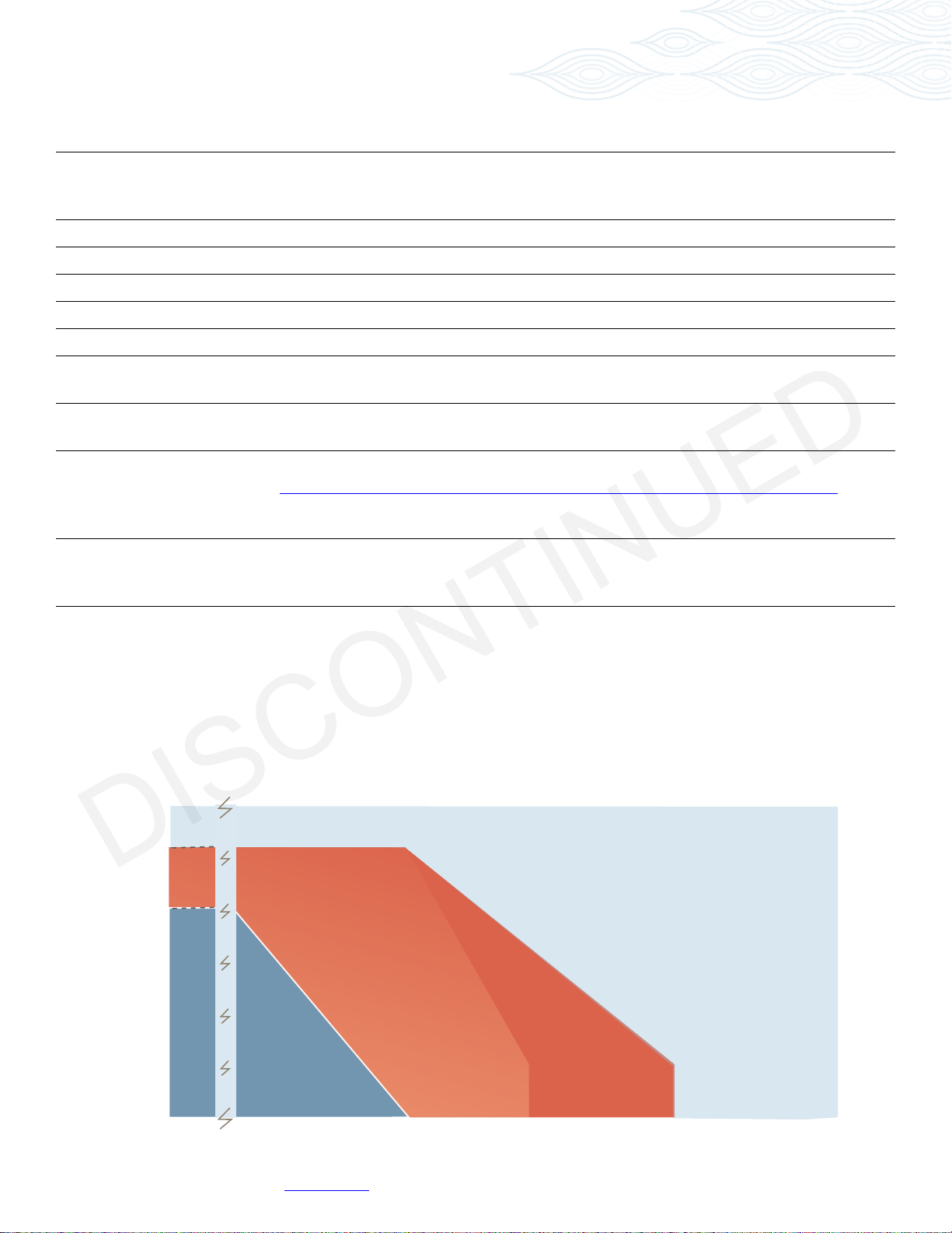
Temperature Range Specication (Analog & Freq.)
Model 29X Transmitter Series
120
110
100
80
60
40
20
295 & 296 296 295 & 296
Standard
High
temperature
2 part pickup
Ultra High
temperature
2 part pickup
Ambient Temperature °C
0
-25
50
100
Process Temperature °C
150 200
225
250
300
Max Machinery, Inc. Discontued: 243 Manual © Copyright 2014 5
Page 6

Installation
DISCONTINUED
For optimum performance, install the ow meter on the discharge side of the pump, in one
of the congurations shown on page 7.
The following items and conditions should be considered:
Location: Install the ow meter in a clean, dry area if possible. Avoid areas with high vibration levels.
Line and Bypass Valves: These valves allow lter cleaning or ow meter removal without completely shutting the system
down and draining the lines. They are important for system start up under conditions which could damage the meter,
such as: air in the lines, solid materials (at room temperature), high temperature materials, or initial line surges.
Filtration: Any dirt present in the system can jam or damage the meter. A 150 micron lter is generally recommended,
although materials with very high viscosities may require a coarser lter. For bidirectional ow applications, use a lter
on each side of the ow meter. Materials with brous or non abrasive particulate matter may have to be run without
lters. Follow the recommendation of your Max Sales Engineer or consult Technical Service.
Clean Plumbing: Before installing the ow meter, clean the inside of the pipe line with compressed air or steam
(especially when using new pipe). Don’t use water, steam, or compressed air on the meter itself! Remove any protective
covering from the anges (if applicable).
Pipe Threading: When installing pipe to the ow meter, support the nearest end cap or both end caps (as in a vise). Don’t
clamp the ow meter body. This avoids possible misalignment of ow meter components when the pipe is screwed tight.
Check for proper ow meter operation by rotating the timing gear through the transmitter mounting hole. It should
move freely and without noise.
High Temperatures: Use the “Vertical Installation” drawing. This minimizes heat transfer by convection from the
ow meter to the transmitter. The transmitter is the most heat sensitive element in the system and the transmitter
manual should be consulted for specic limits. Optional heating uid ports are available for the ow meter to keep it at
operating temperature during standby conditions. For substances that are solid at room temperature, these ports are
generally required to keep the material molten and owing through the meter.
ANSI Flanges: Using the 241, 242 or 243 meters at pressures greater than 500 psi will also require anges. See the
specications and bolt torque table on page 8. Max has bolt kits available for ange installations.
Max Machinery, Inc. Discontued: 243 Manual © Copyright 2014 6
Page 7

Piping Diagrams
HELICAL
FLOW METER
DISCONTINUED
Vertical Installation
VALVE 2
FILTER
VALVE 1
FLOW
BYPA SS
VALVE 3
Horizonal One Way Flow Installation
Flow
Valve 1
Horizonal Two Way Flow Installation
Flow
Valve 1
Filter
Filter Filter
Valve 2
Helical Flow Meter
Bypass
Valve 3
Valve 2
Helical Flow Meter
Bypass
Valve 3
Max Machinery, Inc. Discontued: 243 Manual © Copyright 2014 7
Page 8

ANSI Flange Stud Torque
DISCONTINUED
240 Series ANSI Flange Stud Torque Requirements. This table shows the minimum torque required for a 2:1 tightening
factor at the indicated pressures using zinc plated studs and nuts. These values were calculated using studs with a yield
strength of Sy = 75,000 psi.
Meter
(Flange)
241 (600# Flange) 4 3/4-1 0 24 (33) 49 (67) 73 (99) 200 (271) 47,904
241 (2500# Flange) 4 1-1/8-7 37 (50) 73 (99) 110 (149) 183 (248) 256 (247) 681 (924) 47,789
242 (600# Flange) 8 3/4-10 24 (33) 47 (64) 71 (96) 200 (271) 47,904
242 (1500# Flange) 8 1-8 31 (42) 63 (86) 94 (128) 157 (213) 219 (297) 483 (656) 47,822
243 (600# Flange) 8 7/8-9 53 (72) 106 (144) 159 (216) 322 (437) 47,9 7 2
243 (1500# Flange) 8 1-1/4-7 76 (103) 151 (205) 227 (308) 378 (513) 529 (718) 965 (1310) 47,802
Studs Torque For Line Pressure ft-lb
(N-m)
See notes below
Qty Size 500 1000 1500 2500 3500
Absolute
Max Torque
ft-lb (N-m)
Stress at
Max Torque
(psi)*
Notes:
Using the 241, 242 or 243 meters at pressures greater than 500 psi
ange installations.
For unplated non-lubricated nuts and studs, multiply the above torque by 1.5.
For lubricated nuts and studs, multiply the above torque by 0.9.
For cadmium plated nuts and studs, multiply the above torque by 0.8.
*Stress in bolt calculated for thread root diameter.
Max Machinery, Inc. Discontued: 243 Manual © Copyright 2014 8
will require anges
. Max has bolt kits available for
Page 9

Operation
DISCONTINUED
Determine that the following parameters of your ow metering system
are within specications for the specic 240 Series Meter being used:
Maximum System Pressure (Specications)
Differential Pressure across meter (Pressure Drop Curves)
Maximum Flow Rate (Pressure Drop Curves)
Metered Fluid Temperature (Sales specication, transmitter manual)
If the metered uid is greater than 80°F (28°C) over ambient, see the “High Temperature Start Up” section.
With valves one and two closed, slowly open valve three (bypass) to clear the lines of foreign
particles and air. Slowly open the inlet valve (# l). Slowly open the outlet valve (# 2). Completely close the bypass valve.
No routine maintenance, cleaning, or lubrication of the ow meter is required. A routine
lter cleaning schedule should be established. The system should be shut down if abnormal
noises occur or if unusual differential pressures across the meter are encountered.
High Temperature Start Up: For uids above 150°F (82°C) based on 70°F ambient, a special
procedure is required to prevent thermal shock and permanent damage to the ow meter.
The warm up time is determined by the equation below:
TIME (minutes) = connector size (in inches) x (operating temperature (F) -125)
10
—OR—
TIME (minutes) = connector size (in inches) x (operating temperature (C) -52)
10
Valves one and two must be closed. Open the bypass valve (# 3) in gradual steps until the bypass piping is stabilized at
operating temperature. Open valve one slightly and allow the temperature to stabilize around the ow meter. Valve one
can then be opened completely. Open valve two slightly. The ow meter may make unusual noises or bind at this point.
Leave the valve at this setting until normal meter operation occurs, at which point valve two can be gradually opened all
the way. Slowly close the bypass valve (# 3).
Max Machinery, Inc. Discontued: 243 Manual © Copyright 2014 9
Page 10

Electrical Installation - Wiring
DISCONTINUED
290 Series Transmitters
Removal note: The transmitter does not need to be removed from the ow meter for any eld servicing or adjustments.
Normally, the ow meter and transmitter are shipped back to the factory for calibration or service as a unit. If the
transmitter needs to be removed from the ow meter for installation, be sure to retighten the transmitter snugly in
order to ensure proper sensor alignment.
Mechanical Installation
1. The transmitter is attached to the ow meter’s threaded magnet shield. Hand tighten only. (~ 3 ft-lb)
2. The transmitter lid has four thread paths. To realign the cable, remove the lid and rotate up to 180° and retighten
using an alternate starting point. Tighten to compress the O-ring seal.
Removal
1. Remove electrical connections
2. Unscrew transmitter, using a wrench if necessary.
WARNING
Installation and removal should only be facilitated by trained personnel
Verify transmitter output type (ANALOG or FREQUENCY) before wiring, inappropriate wiring could
result in damaging the circuit.
Moisture Seal Protection
On all models, the housing is designed as a liquid and vapor-tight enclosure. There are O—ring seals at the lid and
possibly also the base of the housing — these need to be fully seated. A properly sealed transmitter will prevent the
formation of damaging moisture inside the housing.
Turck connector Model: The connector is sealed to the lid at the factory and is ready for use.
NPT Model: To ensure a moisture-tight seal, apply appropriate sealant to the threads at installation.
Wiring ANALOG
The electrical connector versions are pre-wired inside the transmitter and ready to accept a mating cable (available from
the factory). The liquid-tight, NPT models need to be wired during installation as shown in the table below:
Analog
Case Ground In-lid Case Blue 3
Common 1 Com Black 4
Power * 2 V+ Brown 1
Signal Output (+) 3 Sig Grey 5
Signal Output (-)** 4 Ret White 2
*Model 29X-xxx-000, 24vdc powered, Model 29X-xxx-100, 12vdc powered
** Signal output is fully isolated: If attached to a true differential input a 10K Ohm pulldown resistor
should be installed between (—) and common at the receiving end.
294 NPT model All Other Models Mating Cable
Wire Color
Turck
Pin #
Max Machinery, Inc. Discontued: 243 Manual © Copyright 2014 10
Page 11

21
4
5
3
Electrical Installation - Wiring
DISCONTINUED
Wiring FREQUENCY
The electrical connector versions are pre-wired inside the transmitter and ready to accept a mating cable (available from
the factory). The liquid-tight, NPT models need to be wired during installation as shown in the table below:
Frequency
Single Phase
Frequency
Case Ground Case Blue 3
Single Phase
Common Com Black 4
Wiring
Power 5-26 Vdc V+ Brown 1
Pulse Output Ph A White 2
N/A NC Grey 5
* A current sinking device produces an output pulse which is the opposite of a sourcing device.
A positive DC voltage must be applied to the wire running between PhA and your PLC. When the
output is triggered, this voltage will be grounded to zero volts. Note: use a 5k ohms resistor to limit
the current ow in the signal line.
Frequency
All Other
Models
All Other Models Mating Cable
Quadrature
Case Ground Case Blue 3
Common Com Black 4
Power 5-26 Vdc V+ Brown 1
Output Phase A Ph A White 2
Output Phase B Ph B Grey 5
Mating Cable
Wire Color
Wire Color
Turck
Pin #
Turck
Pin #
Current Sinking* Wiring
(models 29X-6XX)
V+
V+
0V
Out
Turck Pin #2
Transmitter
Turck Connector
PLC
Digital
Input
Electrical Installation - Wiring
280 Series Transmitters
Wiring
The 6-pin connector version is pre-wired inside the transmitter and is ready to accept a mating cable (available from the
factory). The Liquid-Tight and NPT models need to be wired during installation as shown in the table below:
NPT Models 6-Pin Connector
Circuit Board
Terminal #
Case Ground 1 Green A
Common 2 Black B
Power (+5-24 VDC) 3 Red C
Pulse Output 4 White D
Max Machinery, Inc. Discontued: 243 Manual © Copyright 2014 11
Mating Cable
Wire Color
Pin #
Page 12

Troubleshooting
DISCONTINUED
Trouble Corrective Action
No Flow through meter or high pressure drop across meter
Solidied material blocking rotation
Heat meter to melt material.
Debris blocking rotation
Meter broken
Remove meter from line. Flush with an organic solvent or
petrochemical. Try to work debris out of the meter.
If you nd damaged parts in the meter, return the
meter to the factory for repair.
Fluid is passing through the meter, but there is no indication of ow
Improper hook-up of transmitter Verify that DC power is present at the PCA. Use a
multi-meter to measure the transmitter output
independent of the display or PLC.
Inspect cabling.
Indicated ow does not agree with expected readings
Air in the line
Indicator not calibrated properly
Excessive reverse ow in system
Air bubbles displace the meter just as a liquid would.
If you are over-reporting, verify that there is no air in
the lines.
Verify the K-Factor for the meter in use and compare
this value to the setting used in the display.
Max transmitters have anti-dither functions which can
buffer up to 1 revolution of reverse ow. An incorrect
ow total can be reported if the pumping causes a
ow and ebb of greater than 1 meter revolution.
Max Machinery, Inc. Discontued: 243 Manual © Copyright 2014 12
Page 13

7.53”
(191 mm)
13.10”
(333 mm)
3.00” NPT
6.15”
(156 mm)
243 Helical Flow Meter
DISCONTINUED
CONNECTIVITY/DIMENSIONS
- Top View - - End View -
Max Machinery, Inc. Discontued: 243 Manual © Copyright 2014 13
Page 14

Contact for Repairs
DISCONTINUED
& Calibration Services
Your Max 240 Series Meter should be repaired at the factory or under the direct supervision of the Max Technical
Service Department. Unauthorized repair work may damage the meter and will void the product warranty. Please make
note of model and serial numbers on the ow meter before calling the factory. A return goods authorization number
(RMA) will be issued if the ow meter has to be sent back for repair.
Max Machinery, Inc. Phone: 707-433-2662
33A Healdsburg Ave Fax: 707-433-1818
Healdsburg, CA 95448 www.maxmachinery.com
Max Machinery, Inc. Discontued: 243 Manual © Copyright 2014 14
 Loading...