

Mavix MediaRacer 100 User Manual

---MAVIX---
MediaRacer® 100 [MT0002 - Rev 1.10]
MMeeddiiaaRRaacceerr®® 110000
SSuurrvveeiillllaannccee MMuullttiimmeeddiiaa
GGaatteewwaayy
-- ---- UUSS EERR MMAANNUUAALL ------
--- --- ---
P
P
P R
R
REEE LLLIIIMMMIII NNNAAARRRYYY
-
-
- --- ---

---MAVIX---
MediaRacer® 100 [Preliminar y] 2
T
T
AABBLLEE OOFF
C
C
OONNTTEENNTTS
S
TABLE OF CONTENTS................................................................ ................2
MEDIARACER ® 100 OVERVIEW .................................................................4
INTEGRATED SURVEILLANCE SYSTEMS ..............................................................4
CHAPTER 1 ................................ ................................................................5
MEDIARACER ® 100: SYSTEM DESCRIP TION.............................................. 5
SYSTEM DESCRIPTION ...................................................................................5
CONFIGURATION – DESCRIPTION OF SYSTEM COMPONENTS..................................... 6
FEATURES................................................................ ..................................7
CHAPTER 2 ................................ ................................................................9
MEDIARACER ® 100: END UNITS................................................................. 9
GENERAL DESCRIPTION................................................................................. 9
MEDIA RACER® 100 – FRONT PANEL DESCRIPTION.............................................10
Video Channel............................................................................................................. 10
Serial Data Channel ................................................................................................... 11
CONSOLE LED .......................................................................................................... 11
Serial TRUNK Channel - Network Connector (RJ-45).............................................. 11
TX LED ....................................................................................................................... 11
rX LED ........................................................................................................................ 11
Network Port............................................................................................................... 11
System Indicators ........................................................................................................ 12
MEDIA RACER® 100 – REAR PANEL DESCRIPTION ..............................................13
POWER - DC CONNECTOR ............................................................................14
DIO (Discrete Input/Output) Channels ...................................................................... 14
CHAPTER 3 ................................ ..............................................................15
MEDIARACER ® 100: SPECIFICATION AND FEATURES .............................15
MEDIA RACER® 100 TECHNICAL SPECIFICATION ................................................ 15
CONNECTORS MAPPING TABLE................................ ......................................19
10/100 RJ-45 Connector............................................................................................. 19
SERIAL RS232 (COM 1) & RS485 (COM 2) RJ-45 CONNECTOR............................20
Serial trunk RJ-45 Connector (COM 3)...................................................................... 21
DI (DISCRETE Input) Block Terminal....................................................................... 22
Do (DISCRETE output) Block Terminal..................................................................... 22
CHAPTER 4 ................................ ..............................................................23
MEDIARACER ® 100: INSTALLATION AND CONFIGURATION ...................23
INSTALLATION REQUIREMENTS......................................................................23
POWER CONNECTION ..................................................................................24
CONNECTION TO NETWORK .......................................................................... 25
CONNECTING DEVICES ................................................................................25

---MAVIX---
MediaRacer® 100 [Preliminar y] 3
Connecting Video Sources .......................................................................................... 25
Connecting the Monitor.............................................................................................. 26
Connecting Audio Devices.......................................................................................... 26
Connecting Devices to RS232 and RS232/485 Ports.................................................. 27
Connecting Discrete Input/Output (DIO) Devices ..................................................... 27
CONFIGURATION SETTINGS...........................................................................28
Console Setting........................................................................................................... 28
MediaRacer® 100 Unit Setting................................................................................... 29
System Settings............................................................................................................ 31
Network Settings......................................................................................................... 34
Software Update settings ............................................................................................ 36
Built-In Tests ............................................................................................................... 38
Loading of Configuration Default Values................................................................... 38
Reboot......................................................................................................................... 38
Application Log Screen............................................................................................... 39
ADVANCED CONFIGURATION ........................................................................40
INSTRUCTIONS FOR QUICK SETUP ...................................................................40
CHAPTER 5 ................................ ..............................................................42
MEDIARACER ® 100: OPERATION.............................................................42
MEDIA RACER® LINK MANAGER....................................................................42
Installation of MediaRacer® Link Manager .............................................................. 43
Activating MediaRacer® Link Manager..................................................................... 43
Communications Management Between MediaRacer® 1000 units ........................... 45
Management and Control of Video Devices ............................................................... 47
Management and Control of Audio Devices............................................................... 51
Management and Control of RS232 Devices .............................................................. 53
Management and Control of DIO Devices ................................................................. 55
MEDIA RACER® LINK MANAGER - REMOTE CONFIGURATION TOOL.........................57
Definition of Advanced Configuration Settings.......................................................... 59
Software Updat e.......................................................................................................... 62
Remote Configuration Status...................................................................................... 63
Resetting & Controlling the Operation Mode ............................................................ 64
MAVIEW MANAGEMENT SOFTWARE ............................................66
The MAVIEW API....................................................................................................... 67
MAVIEW Player Software .......................................................................................... 68
CHAPTER 6 ................................ ..............................................................69
MEDIARACER ® 100: TROUBLESHOOTING ...............................................69
NETWORK TROUBLESHOOTING................................ ......................................69
RS232/485 TROUBLESHOOTING.....................................................................70
THE RED LED IS CONSTANTLY LIT.................................................................71
VIDEO TROUBLESHOOTING...........................................................................72
AUDIO TROUBLESHOOTING...........................................................................73

---MAVIX---
MediaRacer® 100 [Preliminar y] 4
M
M
EEDDIIA
A
R
R
AACCEER
R
®
®
110000
O
O
VVEERRVVIIEEW
W
INTEGRATED SURVEILLANCE SYSTEMS
MediaRacer® 100 is a remote intelligent monitoring and surveillance building block for
use in implementing broad surveillance solutions, including transportation, industrial
process control and security applications. MediaRacer® 100 utilizes advanced computer
networking technology to integrate information from multimedia devices (audio, visual
and digital data) in order to provide the user with a reliable, flexible and interactive
monitoring system.
The MediaRacer 100 introduces enhanced capabilities embedded in the product design
considerring the needs of today and the future market.
MediaRacer® 100 enables digital transmission, switching and control of remote
multimedia surveillance devices spread over large areas. Compressed audio and video
information and other digital data are captured by remote sensors and transmitted to the
MediaRacer® 100 unit, where they are processed. The data is then packaged by the
TCP/IP protocol and transmitted over a standard high-speed computer communications
network to the control center.
The challenge facing any monitoring and surveillance system design today is to build a
concept for tomorrow. Systems installed today are often outdated by the time their
implementation has been completed. The key objective is to build an open system that is
never closed to future options and which facilitat es expansion of capacity and
functionality in an efficient and flexible manner. MediaRacer® 100 provides the solution.
MediaRacer® 100 is designed and manufactured by MAVIX. Based on an open system
architecture, the MAVIX Solution brings together the considerable progress made to date
with information networking technology and the sophisticated requirements of current
monitoring systems. The MAVIX System integrates, manages and controls all components
of the monitoring system, including cameras, audio devices, monitors, alarms, sensors, and
controllers.

---MAVIX---
MediaRacer® 100 [Preliminar y] 5
C
C
HHAAPPTTEERR
11
MMEEDDIIAARRAACCEERR®® 110000::
S
S
YYSSTTEEMM
D
D
EESSCCRRIIPPTTIIOON
N
SYSTEM DESCRIPTION
MediaRacer® is a new family of MAVIX Multimedia Gateways, designed to provide high
quality delivery of video, audio and other electronic data using TCP/IP networks.
The flagship member of the family, MediaRacer® 100, features full motion video at
different resolutions (PAL/NTSC), suporting state of the art compression standards, and is
based on low cost, compact design, while maintaining the high -end system qualities that
are found in MAVIX products. MediaRacer® 100 also features unique capabilities for
low-end applications, such as non-managed point-to-point automatic link recognition and
setup, eliminating the need for costly management applications. This allows end users to
tailor the solution to their exact needs and budget.
MediaRacer® 100 offers up to 1 video camera attachment (in the future it will offer two
attachments), a bi-directional audio port, RS232, RS485 and Digital I/O connections, all
using a box the size of a VHS cassette. It facilitates connection of access control devices,
intercoms, Public Address Systems, PTZ (Pan, Tilt, Zoom) for video cameras and so forth.
The product is also planned to feature after future development an IDE connection to an
optional hard disk, allowing users to locally record events. This highly integrated solution
performs as a zone concentrator for numerous video, audio and data devices, eliminating
the need for multiple hardware platforms for different protocols, and thus significantly
reducing the overall cost of the installation.
The MediaRacer platform is generic, meaning that in addition to the MPEG-4 compression
standard supported today, it will be capable of supporting in the future new compression
standards, just by downloading a new s/w version. The product can also perform as a
compressor or a decompressing unit, saving cost in logistics of customers and end users.

---MAVIX---
MediaRacer® 100 [Preliminar y] 6
Small point-to-point applications are easily monitored and controlled by the MediaRacer®
Link Management application, provided with all units. For medium to large applications,
MediaRacer® 100 is fully managed by the MAVIX MAVIEW Management System,
enabling unified monitoring and control of large installations from a single management
console.
MAVIEW software enables video bandwidth and quality to be controlled and adjusted to
fit specific application requirements. Moreover, monitoring a video picture on the
MAVIEW desktop screen is another unique option available that uses the MAVIEW
Player feature.
MediaRacer® 100 is a wide -range solution that can be used by low, medium and large-
sized applications. It supports different video stream bandwidths according to the various
compression types. This capability is achieved by the use of the new, state-of-the-art
MPEG -4 compression standard.
MediaRacer® 100 also allows significant bandwidth savings by optimizing the UDP and
IP packets. It also supports IP Multicast. End users can determine the video quality and
bandwidth budget, simply by defining a configuration parameter during the setting up of
the unit. As bandwidth becomes more available, the end user can improve the video
parameters by means of a simple update of the unit’s configuration parameters. In this way
the MediaRacer® 100 based solution “grows” with the customer budget, greatly reducing
the total life cost of installation.
CONFIGURATION – DESCRIPTION OF SYSTEM
COMPONENTS
MediaRacer® 100, the MAVIX solution to remote intelligent surveillance, is based on
open system architecture. The basic configuration, as seen in Figure 1, contains the
following components:
? End units – total two: One MediaRacer® 100 working as a Camera Side
unit (compression unit), located on the remote side and the other, a
MediaRacer® 100 working as a Monitor Side (decompression unit), located
on the monitor side, usually in the control room.
? Software components:
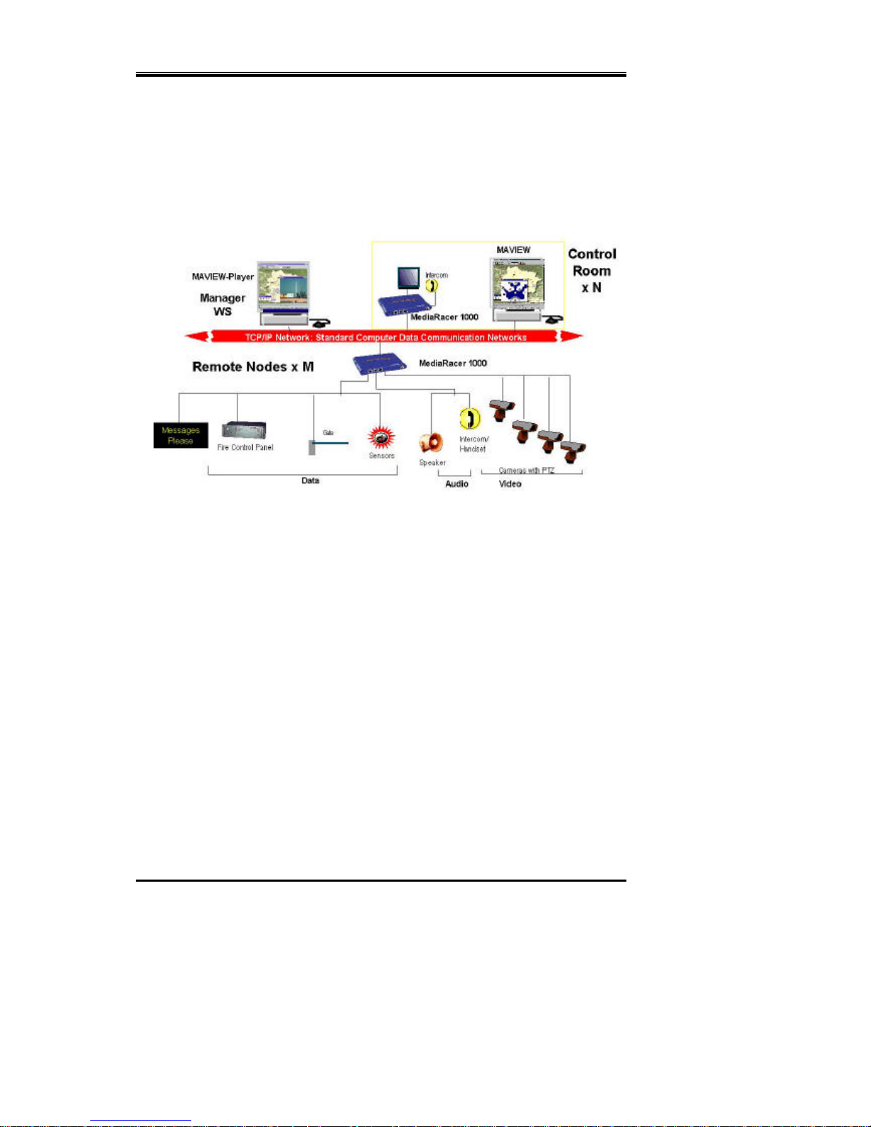
---MAVIX---
MediaRacer® 100 [Preliminar y] 7
√ MediaRacer® Link Manager
√ MAVIEW
√ MAVIEW SDK
Figure 1: Basic Managed Configuration
F EATURES
? The MediaRacer® System supports MAVIX M x N Virtual Matrix
architecture, which enables logical switching of M distributed sources and
N destinations of video, audio and data over IP.
? Remote bandwidth control.
? Multicast Video capability – the same camera can be viewed on several
monitors, over the network.
? Advanced compression of video and audio executed by dedicated hardware
providing real time, full motion – high video quality (PAL/NTSC).
? On-line adjustment of video compression parameters enables the fitting of
specific resolution and motion requirements to the application.
? Video monitoring on desktop, using the MAVIEW -Player.

---MAVIX---
MediaRacer® 100 [Preliminar y] 8
? Direct attachment integrating multiple video, audio and data monitoring
devices.
? Bi-directional audio connections for intercom or other audio monitoring
features.
? Audio Broadcast for public address systems.
? Support for up to two RS-232, and one RS-485 interfaces.
? Support for up to four Opto-isolated Discrete Inputs/Outputs.
? Automatic link setup without the need for a management system (Point to
Point).
? Pre/Post Alarm recording (ready).
? Transparent Serial Channel between Camera and Monitor sides enabling
easy integration with 3rd party devices.
? Low cost latency supporting of a critical mission application, requiring
precise PTZ control.

---MAVIX---
MediaRacer® 100 [Preliminar y] 9
C
C
HHAAPPTTEERR
22
MMEEDDIIAARRAACCEERR®® 110000::
E
E
NNDD
U
U
NNIITTS
S
GENERAL DESCRIPTION
MediaRacer® 100 enables conversion of analog data from its original form, to a digital
packet on one side of a network, back to its original analog form on the other side.
MediaRacer® 100 handles input composite video signals, an output video signal, audio
signals for intercom, serial output data for the camera pan, tilt, zoom, washer, wiper and
heater control, and other discrete input/output data.
MediaRacer® 100 provides the physical connection to the network and remote site
surveillance devices. The information is packaged using the UDP/IP protocol and routed
to the Control Center via the standard data communications network.
MediaRacer® 100 can be attached directly to high-speed standard data communications
networks, using the Ethernet or Fast Ethernet connections (10/100Base-TX), and
optionally to low-speed data networks such as the telephone network (utilizing an optional
built-in modem) ISDN, serial links (supporting AT command), etc, via appropriate
external modems.
MediaRacer® 100 is based in a Codec architecture design.
MediaRacer® 100 Camera side unit is usually located at a remote site, serving as a zone
concentrator for the various devices required for the monitoring and control. The unit
enables communication sessions between remote surveillance devices and control room,
and between remote surveillance devices attached to different units. Each medium (video,
audio, sensors) maintains a separate independent session. In this way the video from unit
A may be delivered to unit B, and concurrently the audio of unit A may be delivered to
unit C. The MediaRacer® 100 monitor side unit is usually located in the control room and

---MAVIX---
MediaRacer® 100 [Preliminar y] 10
enables the viewing of the video pictures taken by the remote cameras on analog monitors.
MEDIARACER® 100 – FRONT PANEL DESCRIPTION
The front panel of the MediaRacer® 100 contains:
? Video Channel (Video In or Video Out)
? Serial Data Channel
? Serial Trunk Chnnel
? Network Port
? System Indicators
VIDEO CHANNEL
VIDEO IN - MediaRacer® 100 Camera Side unit
The VIDEO IN channel consists of one composite video input that facilitate the
attachment from video source - camera or analog video matrix - to the Media Racer 100
Camera Side unit.
The video input connector has it’s own LED. The LED, which is lit, indicates the video
source selected by the user.
VIDEO OUT - MediaRacer® 100 Monitor Side unit
The VIDEO OUT channel has a single connector. An analog monitor can be connected to
this connector, enabling viewing of video pictures taken by the remote cameras.

---MAVIX---
MediaRacer® 100 [Preliminar y] 11
SERIAL DATA CHANNEL
Devices that transfer data, such as PTZ control for video camera, computers, VMS
(Variable Message Sign) boards and other industrial control systems, can be connected to
RS232 (COM 1) and RS485 (COM 2) ports.
The unit supports RS485 Half and Full Duplex communication, selecteble by jumpers.
CONSOLE LED
Console LED located next to Serial Data Connector (RJ -45) indicates, that RS232
(COM1) port is chosen to be a Console Port.
SERIAL TRUNK CHANNEL - NETWORK CONNECTOR (RJ- 45)
Serial Trunk Channel is a modular option for communication. This is in addition to the
primary 10/100Base-TX data trunk channel on -board. The Serial Trunk channel can be
used for standard RS232 communication with all external modem control signals and with
AT command support, built-in V-90 PSTN modem and built-in ISDN modem.
TX LED
The TX LED indicates Transmit activities over the serial trunk network.
RX LED
The RX LED indicates Receive activities over the serial trunk network.
NETWORK PORT
10/100Base-TX - Network Connector
Enables a MediaRacer® 100 unit to be connected to an Ethernet/Fast Ethernet standard
data communication network, complying with the IEEE 802.3U standard.

---MAVIX---
MediaRacer® 100 [Preliminar y] 12
LNK LED
The LNK LED lights when a communication link signal is received in the MediaRacer®
100 unit. The lit LED indicates that a connection to the network has been established.
ACT LED
The ACT LED indicates data activity over the network.
SYSTEM INDICATORS
ON – Power LED
The ON LED lights when the system is connected to a power supply and is switched on.
The ON LED will blink every 5 seconds, which indicates proper system operation.
FLT LED
When the FLT LED is lit or blinking, it indicates one of the following problems:
? The MediaRacer® 100 unit failed during the self-test.
? The system failed to initialize the operation software in Application mode.
? The MediaRacer® 100 unit began the reset cycle.

---MAVIX---
MediaRacer® 100 [Preliminar y] 13
MEDIARACER® 100 – REAR PANEL DESCRIPTION
The rear panel of the MediaRacer® 100 contains:
? Audio Channel
? Power Connector
? DIO (Discrete Input/Output) Channel
AUDIO CHANNEL
The audio channel is designed for stereo capabilites and is used to connect an intercom
(bi-directional channel) or a microphone and speaker connection (two uni-directional
channels) or a public address system (uni-directional channel from one point to multiple
points). The AUDIO OUT connectors are used to connect a speaker to the unit and the
AUDIO IN connector is used to connect a microphone to the unit.
Installation of a public address system in the audio channel requires the attachment of a
microphone on the MediaRacer® 100 Monitor Side unit (control side) and speakers on the
MediaRacer® 100 Camera Side unit on the remote side.

---MAVIX---
MediaRacer® 100 [Preliminar y] 14
POWER - DC CONNECTOR
The POWER DC connector is used to connect the cable of the desktop power supply 5V
to the MediaRacer® 100 unit.
DIO (DISCRETE INPUT/ OUTPUT) CHANNELS
DIO devices, such as sensors (temperature, light etc.), automatic gate opening controls and
alarms can be connected to a Discrete Input/Output (DIO) block terminal. The DIO block
terminal has two dry-contact input and two opto-isolated output ports.
The positive terminal of the DO should be connected to one end of the relay coil, while the
second end is connected directly to the external power supply positive output.
The negative terminal of the DO should be connected to the external power supply GND
output.
The ON/OFF switch can be directly connected between (+) and (–) terminals of the
Discrete Inputs.

---MAVIX---
MediaRacer® 100 [Preliminar y] 15
CCHHAAPPTTEERR 33
M
M
EEDDIIA
A
R
R
AACCEER
R
®
®
110000::
SSPPEECCIIFFIICCAATTIIOONN AANNDD FFEEAATTUURREESS
MEDIARACER® 100 TECHNICAL SPECIFICATION
Video Interface
Coding Algorithm MPEG-4 Up to 6Mbps
Formats PAL or NTSC
Resolution 4SIF, SIF, QSIF *
Frame Rate Up to full frame rate*
Input Form Composite
Impedance
75Ω
Level TV Standard
Output Form Composite
Impedance
75Ω
Level TV Standard
Connector BNC
Cable Length Max. 30 m., without degradation of
color and video parameters
* Dynamic selection using MAVIEW or MediaRacer® Link Manager.

---MAVIX---
MediaRacer® 100 [Preliminar y] 16
Network Interface
IEEE 802.3/802.3U
10/100Base-TX (with Auto-Negotiation) RJ-45
Cable Type CAT5 UTP
Cable Length Max. 100 m.
Audio Interface
Coding Algorithm G.711, G.729A
Bit Rate 64kbps / 8kbps
Inputs RCA headphone jack
Voltage: 160mV RMS MAX
Input Gain: Software adjustable in:
1dB steps from -30dB to +30dB
Impedance: 10kOhm, AC coupled
S/N ratio: > 90dB @ full scale
Output RCA headphone jack
Full scale voltage output: 1V RMS
Output Gain: Software adjustable in:
1dB steps from -30dB to +30dB
Minimum Load: 16O
S/N Ratio: >90Db @ for full scale output

---MAVIX---
MediaRacer® 100 [Preliminar y] 17
Serial Interface
RS-232 & RS-485 (COM1 & COM2) RJ-45
Serial Trunk Interface (optional)
RS-232 (COM 3 Full Control), RJ-45
Discrete Interface Inputs Opto-Isolated
2 Dry Contact Ports
Discrete Interface Outputs Opto-Isolated
Outputs: Voltage Max 24VDC
Current Max 90 mA
Physical Dimensions
Size (WxHxD) 19.5x2.8x14 cm (7.67”x1.1”x5.51”)
Weight 0.5 kgs
Power Supply Mains Connection
Voltage Full Auto Range (+/- 10%) 100-240 VAC
Frequency 47 - 63Hz
Power Consumption 9W Typical (4SIF) 7W Typical (SIF)
Environmental Conditions
Operating Temperature (Indoor) +0° to 50°C (41° to 122°F)
Operating Temperature (Outdoor) -15° to 65°C (5° to 149°F)
Storage Temperature -20° to 70°C (-4° to 158°F)
Operating Humidity 5% to 95% (Non-Condensing)

---MAVIX---
MediaRacer® 100 [Preliminar y] 18
Certifications
Safety UL Listed
CE MARK
Electromagnetic Interference (EMC) FCC 47 CFR part 15 subpart B, Class A
CE, Class A

---MAVIX---
MediaRacer® 100 [Preliminar y] 19
CONNECTORS MAPPING TABLE
10/100 RJ-45 CONNECTOR
Pin Number Signal Name
1 TD+
2 TD-
3 RD+
4 Not Used
5 Not Used
6 RD-
7 Not Used
8 Not Used
Figure 3-1: RJ-45 Connectors – Pins Order

---MAVIX---
MediaRacer® 100 [Preliminar y] 20
SERIAL RS232 (COM 1) & RS485 (COM 2) RJ-
45 CONNECTOR
Pin
Number
RS232
Signal
Description RS485
Signal
Description
1 Not Used RX+ Differential Data
(Half Duplex optional,
TRX+)
2 Not Used RX- Differential Data
(Half Duplex optional,
TRX-)
3 GND Signal Ground GND Signal Ground
4 TxD Transmit Data Not Used
5 RxD Receive Data Not Used
6 Not Used GND Signal Ground
7 Not Used TX+ Differential Data
8 Not Used TX- Differential Data

---MAVIX---
MediaRacer® 100 [Preliminar y] 21
SERIAL TRUNK RJ-45 CONNECTOR (COM 3)
Pin Number Signal Name (for
RS232 only)
Description
1 RTS Request to Send
2 DTR Data Terminal Ready
3 GND Signal Ground
4 TxD Transmit Data
5 RxD Receive Data
6 DCD Data Carrier Detect
7 DSR Data Set Ready
8 CTS Clear to Send

---MAVIX---
MediaRacer® 100 [Preliminar y] 22
DI (DISCRETE INPUT) BLOCK TERMINAL
Pin Number Signal Name
1 IN 1+
2 IN 1-
3 IN 2+
4 IN 2-
DO (DISCRETE OUTPUT) BLOCK TERMINAL
Pin Number Signal Name
1 OUT 1+
2 OUT 1-
3 OUT 2+
4 OUT 2-
 Loading...