

Page 1
Page 2
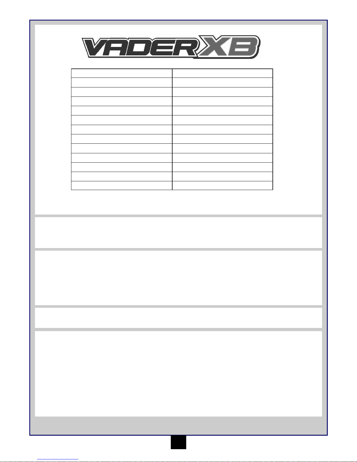
Table of contents
Page
Warranty 1
Specifications 2
Recommended Tools 2
Safety Precautions 2
Items required for operation 2
Charging the battery pack 2
Transmitter 3
Installing the battery pack 4
Turning on the power 4
Turning off the power 4
Trim Setup 4
Fail Safe Operation and Setup 4
Electronic Speed Control Setup 5
Driving 6
Trouble Shooting 7
Maintenance after driving 7
Parts Listing 8
Exploded Diagram Vader XB 37
HAVE FUN! But please read this first !!
We know you will have great fun with your model, but to get the best from your purchase please read this information BEFORE you operate the
model.
1
90 Day Component Warranty
We want you to enjoy your purchase, but please read this first!
This product is covered by a 90 day component warranty from date of purchase. If any part of the product fails as a result of faulty manufacture
during this period then we will repair or replace that part at our discretion.
We do not operate a new for old warranty once the product has been used.
Please note this product is not a toy and it is recommended that children 14 and under are supervised by an adult. It is the responsibility of the
parent or guardian to ensure minors are given appropriate guidance and supervision.
If you suspect there is a problem with the product, for whatever reason, it is the user’s responsibility to investigate and take steps to rectify the
problem before further damage occurs.
Not Covered By Warranty
This is a sophisticated, high performance model and should be treated with care and respect. Every effort has been made to make this product as
strong and durable as possible, however due to the nature of this product, it is still possible to break or damage parts through crashing or extreme
use. Components damaged as a result of crash damage, improper use, lack of maintenance or abuse is not covered by the warranty.
How to Claim Against your Warranty
For warranty claims please first contact your supplying retailer. Do not return the product to your distributor without their prior approval. You may
not need to return the product in full, only the damaged component along with a copy of your purchase receipt. In many cases it is faster and more
cost effective for the user to fit the replacement part(s) to the product & therefore we reserve the right to supply parts only in these instances.
Any returned component that is inspected by your distributor and found to have an invalid warranty claim may be subject to an inspection and
handling fee before it can be returned. Any repairs required as a result of neglect or misuse will be charged before any work is carried out on the
product. If you decide not to have any work carried out the distributor reserves the right to charge a handling and a shipping fee.
Please attach your proof of purchase in the manual as you may need it again in the future.
Page 3
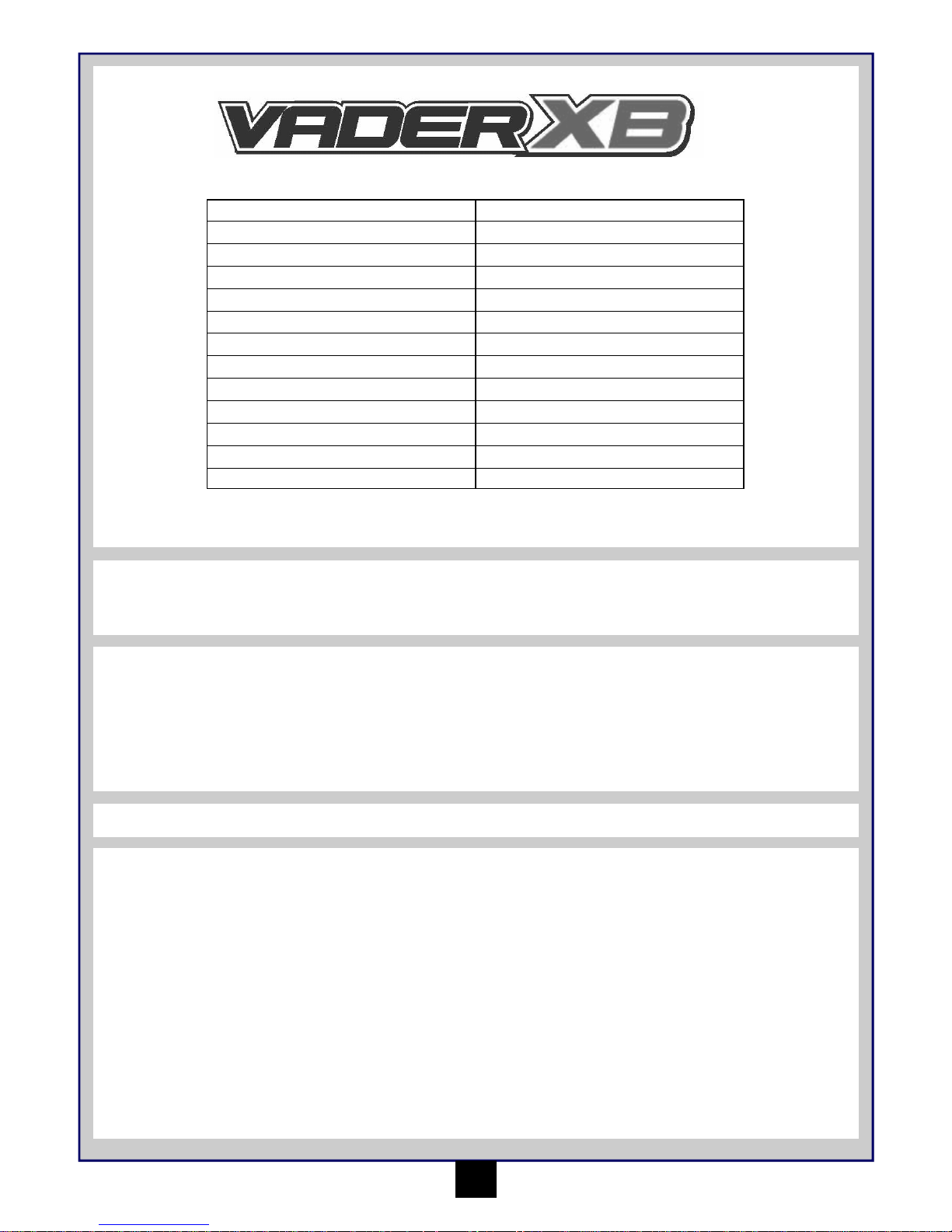
Specifications
2
Safety precautions
This product is an authentic radio controlled vehicle (RC vehicle) and it is not a toy. Read and understand this instruction manual thoroughly
before running the model. If you are not familiar with RC vehicles, we recommend that you ask someone familiar with RC vehicles for advice.
Never connect the rechargeable drive battery in the reverse polarity or disassemble the battery. If the drive battery is used in the wrong way, high
current can be generated and it is very dangerous.
Never run RC models near people or animals, or on public streets or highways. This could cause serious accidents, personal injuries, and/or
property damage.
Recommended Tools
These tools are not included with the product but are recommended for use whilst working with this vehicle
Scissors, Mini Screwdrivers, Hexagonal Screwdrivers 1.5mm, 2.0mm, 2.5mm, 3.0mm, 4-Way Cross Wrench (Small), 4-Way Cross Wrench
(Large), Side Cutters, Needle Nose Pliers
Items required for operation
4 * AA Batteries for the Transmitter
Charging the battery pack
This vehicle does not have any batteries or chargers included.
We recommend you using 2 x 3S (11.1V) LiPo Stick pack hard cased batteries with authentic Deans Connector installed. The connectors must be
a high current type as they will get very hot whilst in use, low current connectors may melt and cause failure and possibly fire.
Always follow the manufacturers guidelines for charging of both the battery and the charger. You cannot use a Ni-MH charger with LiPo batteries
and vice versa.
Cautions
• Always follow charging guidelines from the manufacturer of the battery and the charger you have.
• Always use good quality high current battery connectors, we recommend genuine Deans Connectors.
• Do not use the charger or battery if the wire is frayed or worn. If the wire is frayed or worn a short circuit can cause a fire or burns.
Length 710mm
Width 450mm
Height 276mm
Wheel base 503mm
Drive System 4wd Shaft Drive
Gear Ratio 11.8:1
Ground Clearance 35mm
Diameter of wheel 110mm
Width of wheel 60mm
Motor MM-27BL 980KV
Servo MS-241 20KG
Receiver MRX-242 2.4GHz 4CH
Speed Control MSC-27BL 150A Fwd/Rev
Page 4
3
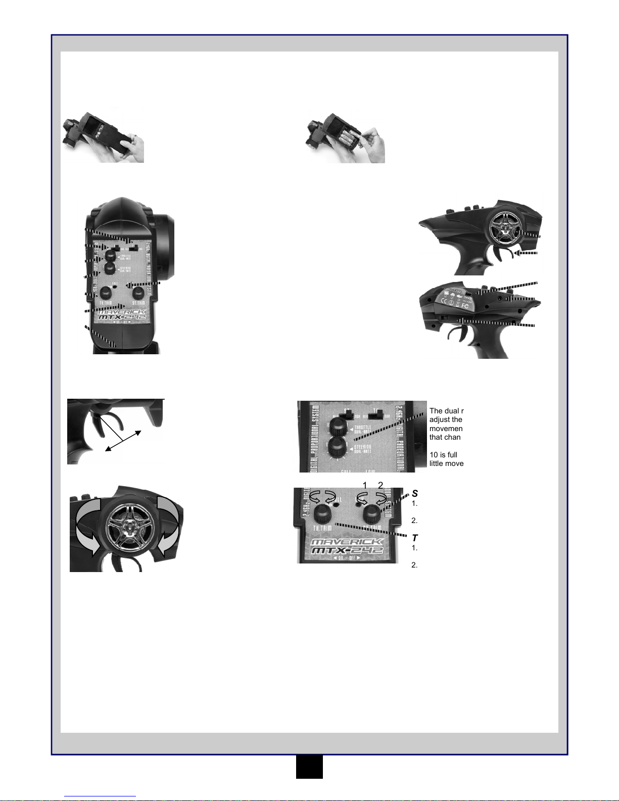
Transmitter
Your Transmitter is an advanced controller designed for the beginner to be easy to use and tune. You will need to follow the steps below to ensure
you prepare the controller correctly for use and understand the adjustment possibilities available.
Turning on the power
Turn on transmitter first and then turn on receiver.
Turn on the transmitter switch and the LED battery indicator will light up.
Turn on the receiver. The automatic set-up of the factory set speed control should
have been completed. If you experience any problems with the speed control settings refer to the Electronic Speed Control Section for correct
setup information.
Preparing the transmitter
Open the battery holding tray to expose the
empty battery slots.
Insert 4 AA batteries into the marked spaces.
Please note the correct direction of the
batteries
Incorrect battery insertion could lead to
damage
Your Transmitter is an advanced controller designed for the beginner to be easy to use and tune. You will need to follow the steps below to ensure
you prepare the controller correctly for use and understand the adjustment possibilities available.
The function switches on the transmitter
1. Throttle Trim
2. Steering Trim
3. Power Switch
4. Steering End Point
dials (left/right lock)
5. Throttle End Point
dials (low/high points)
6. Steering reverse
switch
7. Throttle reverse switch
8. Power LED’s
9. Steering Control
10. Throttle Trigger
11. France Mode Switch
12. Charging Port
13. Throttle Neutral
Position switch
1
5
9
10
Throttle Trigger
2
1
Neutral
1. Push the trigger
forward to Reverse
2. Pull the trigger
backwards to go
forwards and speed up
L
R
Turn the steering wheel to
the left or right to make the
vehicle turn left or right
Dual Rates
The dual rate settings allow you to
adjust the maximum degree of
movement from the servo or ESC on
that channel.
10 is full movement. 0 (Zero) is very
little movement.
2
3
6
4
7
8
11
12
13
Steering Wheel
1 2 1 2
Steering Trim
1. Turn anti clockwise to trim to the
left
2. Turn clockwise to trim to the right
Throttle Trim
1. Turn anti clockwise for more
brake
2. Turn clockwise for more
2.4Ghz technology has done away with the need for long extendable
aerials. The Aerial on your transmitter is located internally
Binding the Transmitter and Receiver
You may need to setup your transmitter to ‘bind’ with the receiver if you change to a new receiver or for any reason lose signal.
• Turn on the Receiver power.
• Press the bind button on the Receiver. The Receiver LED should start flashing.
• Turn on the Transmitter
• When the Receiver LED becomes solid the binding process is completed.
Page 5
4
Installing the battery pack
Open the Velcro straps and place the
battery in the holder. Make sure the
battery is located in the holder and
does not move around.
Fasten the Velcro straps to secure the
battery. If you have a balance lead on
the battery make sure this is secured
by the straps.
Turning off the power
Turn off receiver first and then turn off transmitter.
If you switch off the transmitter first before the R/C car, you may lose control of the R/C car.
• Turn off the receiver switch.
• Turn off the transmitter switch.
• Disconnect the battery connector from the speed control connector.
Trim Setup
If the front tyres are not pointing straight forward with the transmitter on, adjust the steering trim. Then if needed make fine adjustments with the
steering trim whilst driving the vehicle.
If wheels point left, turn clockwise If wheels point right, turn anti-clockwise. If they point straight no adjustment required.
Make sure both Deans connectors are
connected. Never leave them connected when
not in use. Always make sure the connectors
are not connected whilst you store the vehicle.
DISCONNECT THE BATTERY
PACKS AFTER USE!
Fail Safe Operation and Setup
The Receiver has a built in failsafe. The failsafe will automatically go to a pre set position if
• You lose radio signal/power runs out in transmitter
• If you suffer any interference
• If your receiver battery runs out of power
It is advised that you should set the failsafe so that in the event of any of the above situations the
throttle servo should apply brakes to your Nitro car or the throttle disengages to neutral on an
electronic speed control.
To set up your failsafe you must do the following.
• Turn on the transmitter and the receiver
• Set the steering and throttle trims to the neutral position.
• Press the “Fail Safe Set” button on the receiver. The LED will start to flash rapidly.
• While applying the desired amount of brakes/neutral on the transmitter (brakes for engine, neutral for speed control) press the “Fail safe
set” button. The LED will turn solid and the failsafe is set.
To check the failsafe is working you must turn on the R/C unit and then apply throttle with the transmitter. Whilst holding throttle turn off the
transmitter. The throttle servo or ESC should return to the pre-set position. This means the failsafe is working correctly. If your servo or ESC does
not return to the pre-set position then you must try to re-set your failsafe.
4
Page 6
5
Electronic Speed Control
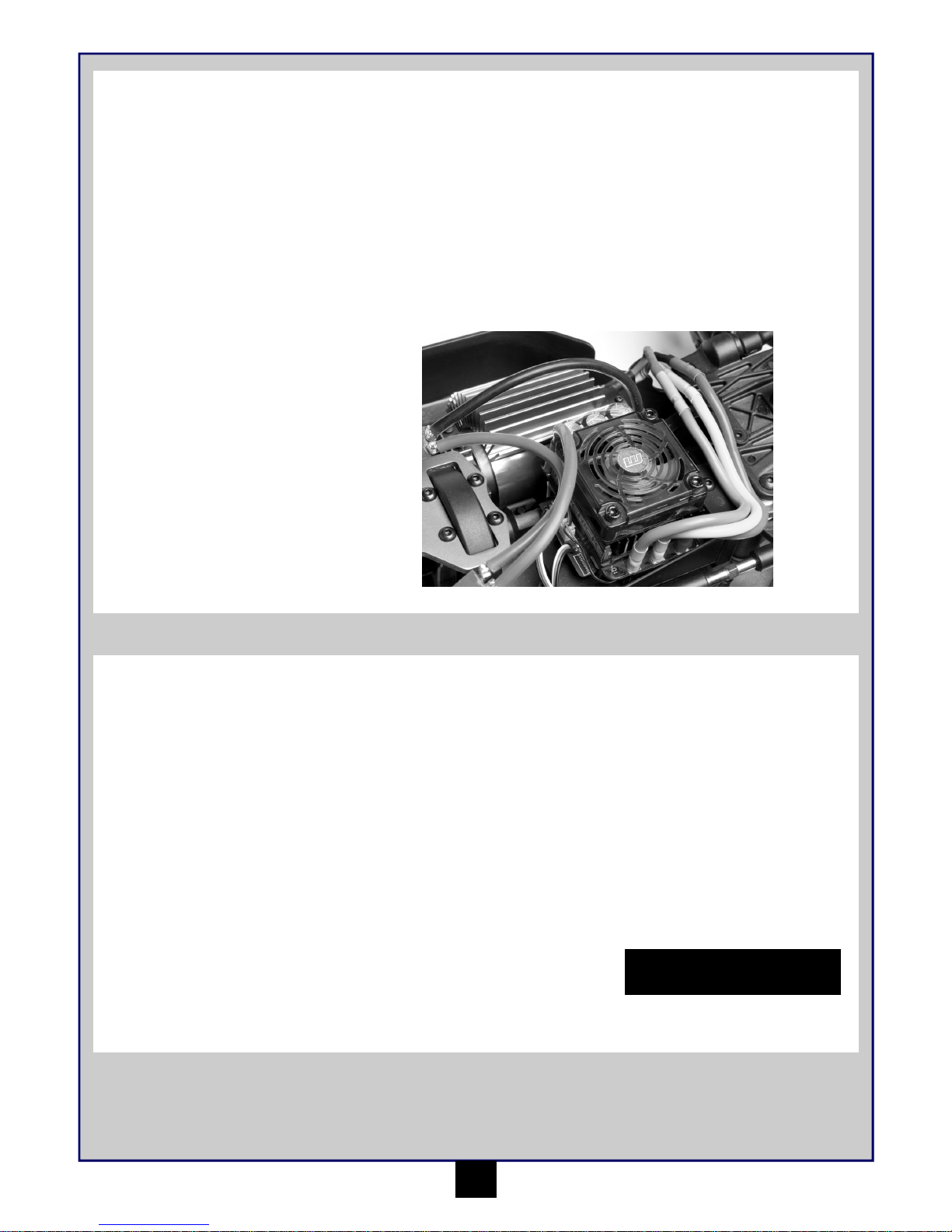
Specification
•
150 Amps continuous current
• Case dimensions: 68mm x 55mm x 45mm
• Silicone Wire 12 Gauge
• Weight 150g with connectors and switch
Setup Procedure
MSC-27BL 150A Brushless ESC
1. With the speed control switch set to off, plug in a suitable battery pack.
2. Make sure the throttle trim is set to the centre, the TH channel is set to REV and the Throttle dual rate is set to 10.
3. Hold the set button on the switch and turn the ESC on.
4. The ESC will beep, leave the throttle trigger in neutral and press the set button once.
5. Hold full throttle on the transmitter and press the set button once.
6. Hold full brake on the transmitter and press the set button once.
Programmable settings
The MSC-27BL ESC has a number of programmable modes that can be altered to suit a variety of functions. Each set of green LED flashes/beep
represents the Programmable Mode (1 flash = Running mode, 2 flashes = Drag brake Force and 3 flashes = Auto-LiPo settings etc..) and each set
of red LED flashes/beep represents that Modes value.
See the table below for all the Programmable Modes and there values. The number 5 is represented by one long flash/beep so it can easily be
identified. This makes the number 6 one long flash/beep followed by one short flash/beep and so on. When you enter the setup mode you need to
keep the button pressed until you enter the desired program mode (green flashes/beeps). Once you reach that mode release the button and that
will allow you to change the mode value (red flashes/beeps).
You need to switch off the ESC to save the settings and then re-do the process to change a different mode or mode value setting. If you lose your
way with setup you can return the unit to default settings by turning on the ESC, keeping the transmitter in neutral and pressing the setup button
for 3 seconds. Both red and green LED’s will flash together 3 times to confirm this.
To enter the programmable settings on the ESC you must do the following
1. While switching on ESC hold down the setup button. Continue to hold the setup button while the LED’s flash
2. Continue to hold the setup button until the green LED’s flash. Each flash represents the programmable mode number.
3. Release the setup button when you reach the desired mode. You are now in the program mode setting.
4. Press the setup button to change the mode value. Each mode value will have different amounts of red LED flashes.
5. In order to save the changes and the settings you must switch off the ESC. When you next switch it back on it will have saved your new
settings. To make further alterations you need to re-enter the mode values again.
• BEC Voltage 5.75V/3A
• Sensorless
• Battery Input: 6-18 cells (7.2V-21.6V) Ni-MH, 2-6 cells (7.4V-22.2V) LiPo
• Burst Current: 1080A
G
R
E
E
N
L
E
D
Programmable
Values
Mode Value RED LED
1 2 3 4 5 6 7 8 9
1. Running Mode For/
Brake
For/Rev/
Brake
For/
Rev
2. Drag Brake
0% 5%
10% 20% 40% 60% 80% 100% Custom
3. Voltage Protect
None
2.6V/Per
Cell
2.8V/
Per Cell
3V/Per
Cell
3.2V/Per
Cell
3.4V/Per
Cell
Custom
4. "DRRS" Punch Level 1 Level 2 Level 3 Level 4
Level 5
Level 6 Level 7 Level 8 Level 9
5. Brake Force 25%
50%
750% 100%
Disable
6. Reverse Force
25% 50%
750% 100%
7. Initial Brake
Drag
Brake
0% 20% 40%
8. Neutral Range
6%
9%
12%
9. "AMTS" Timing 1
2
3 4
5
6 7 8 9
10. Overheat
Protection
Enabled
11. Motor Rotate
CCW
CW
12. LiPo Cells
Auto
Calculate
2 Cells
7.4V
3 Cells
11.1V
4 Cells
14.8V
5 Cells
18.5V
6 Cells
22.2V
Page 7
6
Programmable Values
1. Running Mode - Choose what you want the ESC to do. We do not recommend for/rev.
2. Drag Brake - The amount of brake effect you get when lifting off in neutral, higher value is more brake
3. Voltage Protect - Allows you to have a safe cut off voltage per cell in the battery. Never go below 3.0V/per cell with LiPo. Use ‘None’ for
Ni-MH batteries.
4. DRRS Punch - This is the amount of bottom end power you get, higher levels will increase punch and increase motor temperature.
5. Brake Force - Controls the total braking power, higher value is more brake
6. Reverse Force - Controls speed in reverse, higher value is faster. We recommend keeping this low.
7. Initial Brake - This is the feeling of brakes when you start to apply the brake. Higher value is more brake. If you use a drag brake setting then
you should choose drag brake to keep the feeling correct.
8. Neutral Range - Controls the responsiveness/reaction of the ESC around neutral. Higher value slows down reaction.
9. AMTS Timing - Relates to ultimate top speed, higher value will be faster but will also increase motor temperature.
10. Overheat protection—Protects the ESC, always turned on.
11. Motor Rotate - Clockwise (CW) or Counter Clockwise rotation (CCW)
12. LiPo Cells—Always leave on Auto Calculate for maximum protection.
Brushless Motor
Specification
•
Sensorless Design
• KV: 980
• Max Current: 88ADiameter: 44mm
• Length: 84mm
• Shaft: 5mm
• Max Current: 88AShaft Length: 20mm
• Weight: 610g
• Dual Bearings
• Max Current: 88A
Driving
Driving an R/C car can be very difficult to master but here are some basic tips to help you to understand how to use it before you have your first
attempt
• Drive the vehicle in a very large space, especially until you get the feel of driving the product.
• Do not run on public streets or highways. This could cause serious accidents, personal injuries and/or property damage.
• Do not run in water or sand.
• If you keep pulling the throttle trigger on the transmitter, the vehicle will keep accelerating and run very fast. It is difficult to steer the
vehicle running at high speed until you become used to driving. Drive the vehicle slowly by pulling the throttle trigger to the fullest and
quickly releasing it.
You can turn the vehicle right or left while it is running.
When the vehicle is running toward you, you need to operate the steering wheel in the opposite direction to the operation when the vehicle is
running away from you.
Practice turning the vehicle, referring to the following:
Rather than just paying attention to the direction of the steering wheel, imagine that you are at the centre of the steering wheel, looking ahead of
the vehicle, to turn in the direction you like.
Once you become conformable driving the vehicle, practice driving on a track with cones.
Keep practising until you feel comfortable with the steering, throttle and brake at low speeds.
Once you are feeling comfortable try using reverse.
When you have mastered the basics you will be able to drive at higher speeds in a more controlled fashion.
DISCONNECT THE BATTERY
PACKS AFTER USE!
Page 8
7
Trouble Shooting
Please read this section if you have any fault trying to operate the vehicle
If you encounter any other fault whilst operating the vehicle please contact your local hobby shop or alternatively contact your local distributor.
Problem Cause Remedy
The vehicle does not move
The vehicle does not follow your driving
inputs
Transmitter or receiver is off
Batteries are not placed correctly in the
transmitter
The main battery is not charged enough
Transmitter or receiver is off
Transmitter reverse switches are set
incorrectly
Transmitter End Point Adjustments (EPA)
are set incorrectly
Turn on both the transmitter and receiver
Place batteries in the transmitter properly
Charge the main battery
Turn on both the transmitter and receiver
Check the reverse switch settings
Check that your EPA Dials on your
transmitter.
The front and rear wheels rotate in
opposing directions
Incorrect user differential placement Insert the differential the correct way
Weak batteries in either the transmitter or
the car
Replace batteries in the transmitter and recharge the main battery.
Maintenance after driving
Proper maintenance is very important. Make sure to always perform appropriate maintenance after driving so that you can enjoy driving without
problems next time.
Completely remove all dirt and debris from the vehicle, especially in the suspension, drive shafts and steering parts. Inspect each part and screw
for loosening, missing or damages.
You should always make sure your wheels are tight and parts move freely after and before use.
DISCONNECT THE BATTERY
PACKS AFTER USE!
France Mode
Both the Transmitter and Receiver have a switch labelled “France Mode” “FR-EU”. If you are operating this radio set in France, please make sure
you have the “France Mode” activated.
Please note: Switching from or to “France mode” clears the binding and fail safe settings. Follow the instructions on how to rest these in these
instructions.
Page 9

8
Parts Listing (For Exploded diagram see Pages 37-38)
MV27001 Front Shock Absorber 2 Pcs (Vader XB)
MV27002 Rear Shock Absorber 2 Pcs (Vader XB)
MV27003 Plastic Shock Parts (Vader XB)
MV27004 Front Shock Shafts 2Pcs (Vader XB)
MV27005 Rear Shock Shafts 2Pcs (Vader XB)
MV27006 Shock O Rings (Vader XB)
MV27007 Front Med Spring 2Pcs (Vader XB)
MV27008 Rear Med Spring 2Pcs (Vader XB)
MV27011 Front Lower Suspension Arms 2 Pcs (Vader XB)
MV27012 Rear Lower Suspension Arms 2 Pcs (Vader XB)
MV27013 Steering Link 2 Pcs (Vader XB)
MV27014 Rear Upper Link 2 Pcs (Vader XB)
MV27015 Gear Box Case (Vader XB)
MV27016 Front Shock Tower and Cover (Vader XB)
MV27017 Rear Shock Tower and Cover (Vader XB)
MV27018 Front Upper Link 2 Pcs (Vader XB)
MV27019 Front and Rear Bumper 2 Pcs (Vader XB)
MV27020 Steering Brace Plate (Vader XB)
MV27021 Castor Block 2 Pcs (Vader XB)
MV27022 Suspension Arm Shock Mount 2 Pcs (Vader XB)
MV27023 Body Post Set (Vader XB)
MV27024 Wing Mount Set (Vader XB)
MV27025 Steering Bellcrank & Wire (Vader XB)
MV27026 Suspension Arm Inserts Mid 6 Pcs (Vader XB)
MV27027 Steering Blocks 2 Pcs (Vader XB)
MV27028 Suspension Arm Mount FF/FR 2 Pcs (Vader XB)
MV27029 Suspension Arm Mount RR (Vader XB)
MV27030 Suspension Arm Mount RF (Vader XB)
MV27031 Lower Inner Hinge Pins 6x90mm 4 Pcs (Vader XB)
MV27032 Front Upper Hinge Pins 6*60mm 2 Pcs (Vader XB)
MV27033 18mm Wheel Mount 2 Pcs (Vader XB)
MV27034 Front Roll Bar Set 4mm (Vader XB)
MV27035 Rear Roll Bar Set 4mm (Vader XB)
MV27036 Servo Saver Set (Vader XB)
MV27037 Steering Post 2 Pcs (Vader XB)
MV27038 Rear Wheel Axle 2 Pcs (Vader XB)
MV27039 Front Universal Driveshafts 128mm 2 Pcs (Vader XB)
MV27040 Diff. Joint Cups 2 Pcs (Vader XB)
MV27041 Centre Dogbone Joint Cup 2 Pcs (Vader XB)
MV27042 Diff Drive Pinion 11T 2 Pcs (Vader XB)
MV27043 Steering Link Ball 13mm 4 Pcs (Vader XB)
MV27044 Front Upper Link Ball 12mm 4 Pcs (Vader XB)
MV27045 Lower Shock Mounting Ball 4 Pcs (Vader XB)
MV27046 Upper Shock Mount Standoff 4 Pcs (Vader XB)
MV27047 Rear Dogbones 133mm 2 Pcs (Vader XB)
MV27048 Ball Bearing 19x10x5mm (4 Pcs)
MV27049 Flat Head Screw M4x8mm (12 Pcs)
MV24087 Cap Head Screw M4x12 8 Pcs
MV24088 Cap Head Screw M4x15mm 8 Pcs
MV27050 Cap Head Screw M4x20mm 8 Pcs
MV24089 Cap Head Screw M4x25mm 4 Pcs
MV27051 Cap Head Screw M4x60mm 4 Pcs
MV24091 Cap Head Screw M5x15mm 10 Pcs
MV27052 Cap Head Self Tapping Screw M4x16mm (12 Pcs)
MV27053 Washer 6x16x1mm (6 Pcs)
MV27054 Washer 4x10x1mm (6 Pcs)
MV27055 Suspension Arm Inserts Side 6 Pcs (Vader XB)
MV27056 Front Lower Outer Hinge Pins 5x50.5mm 2 Pcs (Vader XB)
MV27057 Rear Lower Outer Hinge Pins 5x66mm 2 Pcs (Vader XB)
MV24078 Flat Head Screw M5x20mm 8 Pcs
MV24079 Flat Head Screw M5x25mm 4 Pcs
MV27058 Rear Chassis Brace (Vader XB)
MV27059 Motor Heatsink (Vader XB)
MV27060 Battery Mounts (Vader XB)
MV27061 Rear Centre Dogbone 220mm (Vader XB)
MV27062 Front Centre Dogbone 122mm (Vader XB)
MV27063 Motor Mount Plate (Vader XB)
MV27064 Main Aluminium Chassis (Vader XB)
MV27065 Centre Gear Cover (Vader XB)
MV27066 Side Stone Guards (Vader XB)
MV27067 Composite ESC Mount (Vader XB)
MV27068 Rear Aluminium Top Deck (Vader XB)
MV27069 Composite Receiver Box (Vader XB)
MV27070 Front Chassis Brace (Vader XB)
MV27071 Servo Mounts (Vader XB)
MV27072 Motor Mount (Vader XB)
MV27073 Centre Diff Mount (Vader XB)
MV27074 Servo Link (Vader XB)
MV27075 10T Steel Pinion Gear
MV27076 11T Steel Pinion Gear
MV27077 Centre Steel Spur Gear 41 T (Vader XB)
MV27078 Washer 4x8x15mm (4 Pcs)
MV22056 Cap Head Screw M3x10mm (10pcs)
MV24088 Cap Head Screw M4x15mm 8 Pcs
MV24053 Diff Case Set (Blackout MT/Vader XB)
MV24056 Diff. Gear Set (Blackout MT/Vader XB)
MV24060 Diff. Crown Gear 33T (Blackout MT/Vader XB)
MV24067 Washers 3x8x0.8mm 9 Pcs
MV22030 M4 Nylon Nut (8Pcs)
MV24068 M5 Nuts 9 PCS
MV24069 M6 Nuts 6 Pcs
MV22055 Countersunk Screw M3x10mm (8Pcs)
MV24071 Flat Head Screw M4x12mm 12 Pcs
MV24072 Flat Head Screw M4x16mm 12 Pcs
MV24073 Flat Head Screw M4x20mm 12 Pcs
MV24074 Flat Head Screw M4x25mm 8 Pcs
MV24075 Flat Head Screw M5x12mm 12 Pcs
MV24076 Flat Head Screw M5x15mm 12 Pcs
Page 10

9
Parts Listing (For Exploded diagram see Pages 37-38)
MV22056 Cap Head Screw M3x10mm (10pcs)
MV24089 Cap Head Screw M4x25mm 4 Pcs
MV24090 Cap Head Screw M4x30mm 4 Pcs
MV24091 Cap Head Screw M5x15mm 10 Pcs
MV24092 Set Screw M6x6mm 8 Pcs
MV24093 Set Screw M5x5mm 8 Pcs
MV22059 Grub Screw M4x4 (8Pcs)
MV24095 Set Screw M5x10mm 4 Pcs
MV24098 Servo Link Ball 8mm 4 Pcs
MV24111 Servo Horn (Blackout MT/Vader XB)
MV27079 Cap Head Self Tapping Screw M3x12mm (12 Pcs)
MV22062 M3 Nylon Locknut (6Pcs)
MV24101 Body Clips 6 Pcs
MV27080 Pre Painted Mounted Body w/Decals (Vader XB)
MV27082 Moulded Black Rear Wing (Vader XB)
MV27084 Mounted Wheels and Tyres 2 Pcs (Vader XB)
MV27085 Tyres w/Inserts 2 Pcs (Vader XB)
MV27086 Black Wheels 2 Pcs (Vader XB)
MV24109 MS - 241 Steering Servo 20kg
MV27087 MM - 27BL 980KV Brushless Motor
MV27088 MSC - 27BL 150A Brushless Speed Control
Page 11
Sommaire
Page
Garantie 10
Spécification 11
Outils recommandés 11
Précautions de sécurité 11
Éléments nécessaires au bon fonctionnement 11
Charge de la batterie 11
Émetteur 12
Installation du bloc -piles 13
Mise en marche 13
Arrêt 13
Configuration du compensateur 13
Fonctionnement à sécurité intégrée et Configuration 13
Régulateur de vitesse électronique 14
Conduite 14
Dépistage des pannes 15
Entretien après la conduite 15
Liste des pièces 16
Vue éclatée Vader XB 37
10
AMUSEZ-VOUS ! Mais lisez ceci d’abord !!
Nous savons que vous allez bien vous amuser avec votre modèle, mais pour obtenir le meilleur de votre achat, veuillez lire cette information
AVANT de le mettre en marche.
Garantie du composant de 90 jours
Nous souhaitons que vous profitiez de votre achat, mais lisez ceci d’abord !
Ce produit est couvert par une garantie composant de 90 jours à partir de la date d’achat. Si, pendant cette période, l’une des pièces du produit a
un défaut de fabrication, nous la réparerons ou la remplacerons à notre choix.
Nous ne donnerons pas de nouvelle garantie pour une ancienne, une fois que le produit a été utilisé.
Veuillez remarquer que ce produit n’est pas un jouet, et qu’il est recommandé aux moins de 14 ans sous la surveillance d’un adulte. Il est de la
responsabilité des parents ou tuteur de garantir que les mineurs ont l’aide et la supervision nécessaires,
Si vous pensez qu’il existe, pour toute raison, un problème avec le produit, il est de la responsabilité de l’utilisateur de rechercher et de suivre les
pas afin de corriger le problème avant de causer de plus grands dommages.
Non couvert par la garantie
Ceci est un modèle sophistiqué et de haute performance et devra être traité avec soin et respect. Tous les efforts ont été faits pour rendre ce
produit aussi fort et durable que possible, toutefois, il est possible de casser ou d’endommager des pièces après un choc ou un usage extrême.
Les composants endommagés suite à une collision, un usage incorrect, un manque d’entretien ou des mauvais traitements ne sont pas couverts
par la garantie.
Comment revendiquer votre garantie
Pour les droits de garantie, veuillez prendre d’abord contact avec votre fournisseur. Ne renvoyez pas le produit à votre distributeur sans leur
accord préalable. Vous n’avez pas à renvoyer le produit en entier, mais seulement le composant endommagé avec une copie de votre bon
d’achat. Dans beaucoup de cas, il est plus rapide et rentable pour l’usager de monter le(s) pièce(s) de rechange sur le produit et dans ce cas,
nous nous réservons le droit de ne fournir des pièces que dans ce cas.
Tout composant retourné et inspecté par notre distributeur ne possédant pas une garantie valable, peut être sujet à des frais d’inspection et de
manipulation avant sa réexpédition. Toutes les réparations nécessaires suite à une négligence ou mauvaise utilisation seront facturées avant le
début de tout travail sur le produit. Si vous décidez de ne réaliser aucun travail, le distributeur se réserve le droit de facturer des frais de
manipulation et d’expédition.
Veuillez joindre votre preuve d’achat à ce manuel car vous pourrez en avoir besoin à l’avenir.
Page 12
Specifications
11
Éléments obligatoires pour le fonctionnement - 4 * piles AA pour l’émetteur
Outils recommandés
Ces outils ne sont pas fournis avec le produit mais leur utilisation est recommandée pour travailler avec ce véhicule
Ciseaux, mini tournevis, Pinces a bec effile, Tounevis hexagonaux 1.5mm, 2.0mm, 2.5mm, 3.0mm, Cle en croix (petite), Cle en croix (grande),
Pinces coupantes de cote.
Mesures de sécurité
Ce produit est un vrai véhicule radiocommandé et ce n’est pas un jouet. Lisez avec attention ce manuel d’instructions avant de mettre le modèle
en marche. Si vous n’êtes pas familiarisé avec les véhicules radiocommandés, nous vous recommandons de demander le conseil pour qui cela
est familier.
Ne connectez jamais la batterie de traction rechargeable en inversant les pôles ni ne démontez la batterie. Si la batterie de traction est utilisée en
sens inverse, un courant élevé peut être engendré et cela est très dangereux.
Ne mettez jamais des modèles radiocommandés en marche près de personnes ou d’animaux, ou dans des lieux publics. Cela peut provoquer des
accidents sérieux, des blessures, et/ou des dommages matériels.
Charge de la batterie
Ce véhicule n'a aucune batterie ou aucun chargeur inclus(e).
Nous recommandons que vous utilisiez 2 batteries à logement rigide 3S (11.1V) LiPo Stick avec un authentique connecteur Deans. Les
connecteurs doivent être de type haute tension car ils deviendront très chauds en cours d'utilisation et des connecteurs basse tension pourraient
fondre et provoquer une panne ou un incendie.
Respectez toujours les directives des fabricants pour charger la batterie et le chargeur. Vous ne pouvez pas utiliser de chargeur Ni-MH avec des
batteries LiPo et vice versa.
Avertissements
• Respectez toujours les directives de charge du fabricant de la batterie et du chargeur en votre possession.
• Utilisez toujours des connecteurs de batterie haute tension de bonne qualité. Nous recommandons de véritables connecteurs Deans.
• N'utilisez ni le chargeur, ni la batterie si le câble est usé ou abîmé. Dans ce cas, un court-circuit pourrait provoquer un incendie ou des
brûlures.
Longueur 710mm
Largeur 450mm
Hauteur 276mm
Empattement 503mm
Entraînement 4x4 Entraînement arbre
Rapport de vitesse 11.8:1
Garde au sol 35mm
Diamètre de roue 110mm
Largeur de roue 60mm
Moteur Taille MM-27BL 980KV
Servo MS-241 20KG
Récepteur MRX-242 2.4GHz 4CH
Contrôle vitesse MSC-27BL 150A sans balai ESC
Page 13

12
Émetteur
Votre émetteur est un régulateur avancé conçu pour faciliter l’utilisation et le réglage pour le débutant. Vous devrez suivre les étapes ci-dessous
pour vous assurer que vous avez préparé correctement le régulateur et que vous avez compris les possibilités disponibles de réglage.
Préparation de l’émetteur
Ouvrez la plaque de retenue des piles pour
découvrir les fentes des piles vides.
Insérez 8 piles AA dans les espaces marqués
à cet effet. Veuillez faire attention au sens
correct des piles.
L’insertion incorrecte des piles peut pro-
Votre émetteur est un régulateur avancé conçu pour faciliter l’utilisation et le réglage pour le débutant. Vous devrez suivre les étapes ci-dessous
pour vous assurer que vous avez préparé correctement le régulateur et que vous avez compris les possibilités disponibles de réglage.
Les commandes de fonction de l’émetteur
1. Compensation des gaz
2. Compensateur de
direction
3. Interrupteur
d'alimentation
4. Cadrans d’extrémité de
direction (verrouillage
gauche/droite)
5. Cadrans d’extrémité
d'accélération (points
bas/élevés)
6. Interrupteur marche
arrière direction
7. Interrupteur marche
arrière accélérateur
8. LED d'alimentation
9. Commande de direction
(roue)
10. Enclencheur des gaz
11. Commutateur mode
France
12. Port de chargement
13. Commutateur position
neutre accélérateur
1
5
9
10
Commande d’accélérateur
2
1
1. Poussez l’enclencheur
vers l’avant pour la
marche arrière
2. Tirez l’enclencheur
vers l’arrière pour
avancer et accélérer
L
R
Tournez la roue directrice
vers la gauche ou la droite
pour que le véhicule aille
dans cette direction.
Cadrans d’extrémité
Les réglages à double taux vous
permettent de régler le degré de
mouvement maximum du dispositif
servo ou ESC sur ce canal.
10 est le mouvement complet. 0
(zéro) est un très petit mouvement.
2
3
6
4
7
8
11
12
13
Roue directrice
1 2 1 2
Régulateur de direction
1. Tournez vers la gauche pour orienter
vers la gauche.
2. Tournez vers la droite pour orienter
vers la droite.
Point Mort
La technologie 2.4Ghz a éliminé la nécessité de disposer de longues
antennes extensibles. L'antenne de votre transmetteur est située à
l'intérieur de celui-ci.
Associer le transmetteur et le récepteur
Vous devrez peut-être régler votre transmetteur afin qu'il 's'associe' au récepteur si vous utilisez un nouveau récepteur ou si vous perdez le signal,
pour quelque raison que ce soit.
• Allumez l'alimentation du récepteur.
• Appuyez sur le bouton d'association du récepteur. La LED du récepteur devrait commencer à clignoter.
• Allumez le transmetteur.
• Lorsque la LED du récepteur devient fixe, le processus d'association est terminé.
Régulateur d’accélérateur
1. Tournez vers la gauche pour freiner
plus fort.
2. Tournez vers la droite pour accélérer
plus fort.
Mise en marche
Allumez d’abord l’émetteur puis le récepteur.
Allumez l’émetteur et l’indicateur de batterie Del s’allume.
Allumez le récepteur. La configuration automatique du contrôle de vitesse ajusté en usine devra être finie. Si vous rencontrez des problèmes avec
les paramètres de contrôle de la vitesse, reportez-vous à la partie de Contrôle de vitesse électronique pour une information adéquate de
configuration.
Page 14

13
Installation du bloc -piles
Ouvrez les bandes Velcro et placez la
batterie dans le logement. Assurez-vous
que la batterie est bien dans le logement et
ne se déplace pas.
Serrez les bandes Velcro pour fixer la
batterie. Si vous avez un fil de sortie
d'équilibre sur la batterie, assurez-vous
qu'il est tenu par les bandes.
Arrêt
Éteignez d’abord le récepteur puis l’émetteur.
Si vous éteignez l’émetteur avant la voiture radiocommandée, vous pouvez perdre le contrôle de la voiture.
• Éteignez l’interrupteur du récepteur.
• Éteignez l’interrupteur de l’émetteur
• Déconnectez le connecteur des piles du connecteur de contrôle de vitesse.
Configuration du compensateur
Si les pneus avant ne sont pas orientés vers l’avant avec l’émetteur en marche, ajustez le régulateur de direction. Puis au besoin, effectuez des
réglages plus précis avec le régulateur de direction tout en conduisant le véhicule.
Si elles vont tout droit, aucun réglage n’est à
réaliser.
Si les roues vont vers la gauche, tournez
à droite.
Si les roues vont vers la droite, tournez à
gauche.
Veillez à ce que les deux connecteurs Deans
soient connectés. Ne les laissez jamais
connectés lorsqu'ils ne sont pas utilisés.
Veillez toujours à ce que les connecteurs ne
soient pas connectés lorsque vous stockez le
véhicule.
Fonctionnement et réglage de la sécurité intégrée
Le récepteur dispose d'une sécurité intégrée. Celle-ci se mettra automatiquement en position
de préréglage si :
• Vous perdez le signal radio / l'alimentation s'arrête dans le transmetteur
• Vous subissez une interférence
• La batterie de votre récepteur n'est plus alimentée
Nous vous recommandons de régler la sécurité intégrée de manière à ce que le dispositif servo
de l'accélérateur fasse freiner votre voiture Nitro ou à ce que l'accélérateur débraye en position
neutre sur une commande de vitesse électronique au cas où l'une des situations ci-dessus se
produirait.
Pour régler votre sécurité intégrée, vous devez faire ce qui suit :
• Allumez le transmetteur et le récepteur
• Placez la direction et les garnitures de l'accélérateur en position neutre.
• Appuyez sur le bouton « Fail Safe Set » du récepteur. La LED commencera à clignoter rapidement.
• Tout en appliquant le freinage désiré / la position neutre sur le transmetteur (freins pour le moteur, position neutre pour le contrôle de
la vitesse), appuyez sur le bouton « Fail Safe Set ». La LED sera fixe et la sécurité intégrée sera réglée.
Pour vérifier que la sécurité intégrée fonctionne, vous devez allumer l'unité R/C puis appliquer l'accélérateur avec le transmetteur. Eteignez le
transmetteur tout en maintenant l'accélérateur. Le disposition servo de l'accélérateur ou l'ESC devrait revenir en position de préréglage. Cela
signifie que la sécurité intégrée fonctionne correctement. Si le disposition servo ou l'ESC ne revient pas en position de préréglage, vous devez
essayer de régler à nouveau votre sécurité intégrée.
Page 15

14
Régulateur de vitesse électronique
Spécification
• 150 Amp. courant continu
• Dimensions du logement : 68mm x 55mm x 45mm
• Câble silicone calibre 12
• Poids 150g avec connecteurs et commutateur
Procédure d'installation
MSC-27BL 150A sans balai ESC
1. Lorsque le commutateur de contrôle de la vitesse est en position d'arrêt, branchez un pack de batteries adéquat.
2. Vérifiez que la garniture du papillon des gaz est bien au centre, que le canal TH est en position REV et que le papillon des gaz à double
taux est réglé sur 10.
3. Maintenez le bouton de configuration sur le commutateur et allumez l'ESC.
4. L'ESC émettra un bip, placez le déclencheur des gaz en position neutre et appuyez sur le bouton de configuration une fois.
5. Maintenez le papillon des gaz à fond sur le transmetteur et appuyez sur le bouton de configuration une fois.
6. Maintenez les freins à fond sur le transmetteur et appuyez sur le bouton de configuration une fois.
Réglages programmables
Le MSC-27BL ESC dispose de plusieurs modes programmables qui peuvent être modifiés pour s'adapter à un grand nombre de fonctions.
Chaque ensemble de flashes LED verts/bips représente le Mode programmable (1 flash = Mode fonctionnement, 2 flashes = Force frein de
ralentissement et 3 flashes = réglages Auto-LiPo, etc.) et chaque ensemble de flashes LED rouges/bips représente cette valeur des Modes.
Voir le tableau ci-dessous pour tous les modes programmables et leurs valeurs. Le numéro 5 est représenté par un long flash/bip, ce qui permet
de l'identifier facilement. Ainsi, le numéro 6 est un long flash/bip suivi par un flash/bip court, etc. Lorsque vous entrez en mode réglage, vous
devez maintenir le bouton enfoncé jusqu'à ce que vous vous trouviez dans le mode du programme désiré (flashes/bips verts). Une fois que vous
êtes dans ce mode, relâchez le bouton et vous pourrez changer la valeur du mode (flashes/bips rouges).
Vous devez éteindre l'ESC pour enregistrer les réglages puis recommencer le processus pour passer à un mode différent ou à une réglage
différent de la valeur du mode. Si vous ne vous y retrouvez pas dans le réglage, vous pouvez rétablir les paramètres par défaut en allumant
l'ESC, en maintenant le transmetteur en position neutre et en appuyant sur le bouton de configuration pendant 3 secondes. Les LED rouges et
vertes clignoteront ensemble 3 fois pour confirmer la réussite de l'opération.
Pour entrer dans les réglages programmables sur l'ESC, vous devez faire ce qui suit :
1. Pendant que vous mettez l'ESC en marche, maintenez le bouton de configuration enfoncé. Restez ainsi pendant que les LED clignotent.
2. Poursuivez jusqu'à ce que les LED vertes clignotent. Chaque flash représente le numéro du mode programmable.
3. Relâchez le bouton lorsque vous atteignez le mode désiré. Vous vous trouvez à présent dans les réglages du mode de programmation.
4. Appuyez sur le bouton de configuration pour modifier la valeur du mode. Chaque valeur de mode aura des nombres différents de flashes de
LED rouge.
5. Pour sauvegarder ces changements et les paramètres, vous devez éteindre l'ESC. Lorsque vous l'allumerez à nouveau, il aura enregistré
vos nouveaux paramètres. Pour effectuer d'autres modifications, vous devez entrer à nouveau les valeurs du mode.
• Voltage BEC 5.75V/3A
• Sans capteur
• Entrée batterie : 6-18 cellules (7.2V-21.6V) Ni-MH, 2-6 cellules
(7.4V-22.2V) LiPo
• Courant d'explosion : 1080A
L
E
D
V
E
R
T
E
Valeurs
programmables
Valeur mode LED ROUGE
1 2 3 4 5 6 7 8 9
1. Mode
fonctionnement
For/Brake
For/Rev/
For/Rev
2. Freinage de
ralentissement
0% 5%
10% 20% 40% 60% 80% 100% Custom
3. Protection voltage
None
2.6V/Per
Cell
2.8V/
Per Cell
3V/Per
Cell
3.2V/Per
3.4V/
Per Cell
Custom
4. Punch « DRRS » Level 1 Level 2 Level 3 Level 4
Level 5
Level 6 Level 7 Level 8 Level 9
5. Force de freinage 25%
50%
75% 100%
Disable
6. Force en marche
arrière
25% 50%
75% 100%
7. Freinage initial
Drag
0% 20% 40%
8. Champ neutre
6%
9%
12%
9. Timing « AMTS » 1
2
3 4
5
6 7 8 9
10. Protection contre
la surchauffe
Enabled
11. Rotation moteur
CCW
CW
12. Cellules LiPo
Auto
2 Cells
7.4V
3 Cells
11.1V
4 Cells
14.8V
5 Cells
18.5V
6 Cells
22.2V
Page 16

15
Valeurs programmables
1. Mode fonctionnement - Choisissez ce que vous voulez que fasse l'ESC. Nous ne le recommandons pas pour /rev.
2. Frein de ralentissement - La quantité de freinage que vous obtenez lorsque vous relevez vers une valeur neutre, plus élevée, est un
supplément de freinage
3. Protection du voltage - Vous permet d'avoir un voltage de coupure sûr par cellule dans la batterie. Ne descendez jamais en dessous de
3.0V/par cellule avec LiPo. Utilisez 'Aucun' pour les batteries Ni-MH.
4. Punch DRRS - C'est la quantité de puissance électrique que vous obtenez à l'extrémité inférieure. Les niveaux supérieurs augmenteront le
punch et augmenteront la température du moteur.
5. Force de freinage - Contrôle la puissance de freinage totale, plus la valeur est élevée, plus le freinage est puissant.
6. Force en marche arrière - Contrôle la vitesse en marche arrière, plus la valeur est élevée, plus vous allez vite. Nous recommandons que
cette valeur reste peu élevée.
7. Freinage initial - C'est la sensation de freinage lorsque vous commencez à appliquer les freins. Plus la valeur est élevée, plus le freinage est
important. Si vous utilisez une configuration de frein de ralentissement, vous devez choisir le freinage de ralentissement pour que la
sensation reste correcte.
8. Champ neutre - Contrôle la réactivité/réaction de l'ESC autour du neutre. Plus la valeur est élevée, plus la réaction est ralentie.
9. Timing AMTS - Se rapporte à la vitesse maximale finale. Plus la valeur est élevée, plus vous allez vite mais plus la température du moteur
augmente également.
10. Protection contre la surchauffe - Protège l'ESC, toujours allumé.
11. Rotation moteur - Dans le sens des aiguilles d'une montre (SAM) ou dans le sens inverse des aiguilles d'une montre (SIAM).
12. Cellules LiPo - Laissez toujours sur calcul automatique pour une protection maximale.
Moteur sans balai
Spécification
• Concept sans capteur
• KV : 980
• Courant max. : 88A Diamètre : 44mm
• Longueur : 84mm
• Arbre : 5mm
• Courant max. : 88A
• Longueur de l'arbre : 20mm
• Poids : 610g
• Doubles coussinets
• Courant max. : 88A
Conduite
La conduite d’une voiture radiocommandée peut être très difficile à maîtriser mais voici certains trucs de base pour vous aider à comprendre
comment l’utiliser avant votre première tentative.
• Conduisez le véhicule dans un endroit très grand, jusqu’à ce que vous ressentiez la conduite de ce produit.
• Ne mettez pas en marche dans des endroits ou voies publics. Cela peut provoquer des accidents sérieux, des blessures, et/ou des
dommages matériels.
• Ne faites pas marcher dans le sable ou l’eau.
• Si vous maintenez le déclencheur d’accélération de l’émetteur, le véhicule accélérera de plus en plus et ira très vite. Il est difficile de
manœuvrer le véhicule à grande vitesse jusqu’à ce que vous utilisiez l’entraînement. Conduisez doucement le véhicule en tirant le
déclencheur d’accélération à fond et en le relâchant aussitôt.
Vous pouvez faire tourner le véhicule à droite ou à gauche pendant son fonctionnement.
Lorsque le véhicule avance vers vous, vous devez mettre la roue directrice en sens inverse à sa marche lorsque il s’éloigne de vous.
Exercez-vous à faire virer le véhicule en vous reportant à ce qui suit :
Plutôt que de ne prêter attention qu’au sens de la roue directrice, imaginez que vous êtes au centre de la roue directrice, en regardant face au
véhicule pour tourner dans le sens que vous souhaitez.
Une fois que vous vous sentez à l’aise pour conduire le véhicule, exercez-vous à conduire sur une piste avec des cônes.
Continuez à pratiquer jusqu’à ce que vous vous sentiez à l’aise avec la direction, l’accélération et le frein à de basses vitesses.
Une fois que vous êtes à l’aise, essayez en marche arrière.
Lorsque vous maîtrisez les bases, vous serez capable de conduire à de plus grandes
vitesses d’un mode contrôlé.
Page 17

16
Entretien après la conduite
Un entretien adéquat est très important. Réalisez toujours un entretien adéquat après la conduite pour que vous puissiez profiter de la conduite
sans aucun problème la fois suivante.
Enlevez complètement toute saleté et tout débris du véhicule, surtout des suspensions, des arbres de transmission et des pièces de direction.
Inspectez chaque pièce et vis contre tout desserrement, absence ou dommages.
Vous devrez toujours vérifier que vos roues sont bien serrées et que les pièces possèdent un mouvement libre avant et après chaque utilisation.
Dépannage
Veuillez lire cette partie si vous rencontrez un défaut en essayant de faire marcher votre véhicule.
Si vous rencontrez un autre défaut lors du fonctionnement du véhicule, veuillez prendre contact avec votre magasin de modélisme local ou avec
notre distributeur local.
Problème Cause Solution
Le véhicule ne bouge pas
Le véhicule ne suit pas vos commandes
de conduite
L’émetteur ou le récepteur est éteint
Les piles ne sont pas correctement
installées dans l’émetteur
La batterie principale n’est pas assez
chargée
L’émetteur ou le récepteur est éteint
Les interrupteurs inverses de l’émetteur
sont mal réglés
Les ajustements d’extrémité (EPA) de
l’émetteur sont mal ajustés
Allumez l’émetteur et le récepteur
Mettez correctement les piles dans l’émetteur
Chargez la batterie principale
Allumez l’émetteur et le récepteur
Vérifiez les paramètres de l'interrupteur
inverse
Vérifiez les cadrans d’EPA de votre émetteur
Les roues avant et arrière tournent dans
des directions opposées
Emplacement différentiel de l’usager
incorrect
Insérez dans le bon sens le différentiel
Fuite des piles de l'émetteur et du
récepteur
Installez de nouvelles piles
Mode France
Le transmetteur et le récepteur ont tous deux un commutateur portant le nom "France Mode" "FR-EU". Si vous utilisez cette radio en France,
assurez-vous que l'option "France Mode" est activée.
Remarque : Le passage en mode France ou UE supprime la connexion et les paramètres de sûreté intégrée. Suivez les instructions pour
procéder
Page 18

17
Liste des Pièces (Pour le diagramme éclaté voir les pages 37-38)
MV27001 Amortisseur de chocs avant 2 pcs (Vader XB)
MV27002 Amortisseur de chocs arrière 2 pcs (Vader XB)
MV27003 Pièces choc plastique (Vader XB)
MV27004 Arbres choc avant 2 pcs (Vader XB)
MV27005 Arbres choc arrière 2 pcs (Vader XB)
MV27006 Joints toriques choc (Vader XB)
MV27007 Ressort moyen avant 2 pcs (Vader XB)
MV27008 Ressort moyen arrière 2 pcs (Vader XB)
MV27011 Bras de suspension inférieurs avant 2 pcs (Vader XB)
MV27012 Bras de suspension inférieurs arrière 2 pcs (Vader XB)
MV27013 Articulation de direction 2 pcs (Vader XB)
MV27014 Bielle supérieure arrière 2 pcs (Vader XB)
MV27015 Carter de boîte de vitesse (Vader XB)
MV27016 Tour et couvercle choc avant (Vader XB)
MV27017 Tour et couvercle choc arrière (Vader XB)
MV27018 Bielle supérieure avant 2 pcs (Vader XB)
MV27019 Amortisseur avant et arrière 2 pcs (Vader XB)
MV27020 Plaque de renfort de direction (Vader XB)
MV27021 Bloc Castor 2 pcs (Vader XB)
MV27022 Bras de suspension monture anti-vibration 2 pcs (Vader XB)
MV27023 Ensemble montant carrosserie (Vader XB)
MV27024 Ensemble monture dans l'aile
MV27025 Levier coudé et câble de direction (Vader XB)
MV27026 Bras de suspension inserts moyens 2 pcs (Vader XB)
MV27027 Blocs de direction 2 Pcs (Vader XB)
MV27028 Bras de suspension monture FF/FR 2 pcs (Vader XB)
MV27029 Bras de suspension monture RR (Vader XB)
MV27030 Bras de suspension monture RF (Vader XB)
MV27031 Axes de charnière intérieurs inférieurs 6x90mm 4 pcs
(Vader XB)
MV27032 Axes de charnière supérieurs avant 6*60mm 2 pcs (Vader
XB)
MV27033 Coupelle roue 18mm 2 pcs (Vader XB)
MV27034 Ensemble arceau de sécurité avant 4mm (Vader XB)
MV27035 Ensemble arceau de sécurité arrière 4mm (Vader XB)
MV27036 Ensemble sauve servo (Vader XB)
MV27037 Montant direction 2 pcs (Vader XB)
MV27038 Essieu roue arrière 2 pcs (Vader XB)
MV27039 Arbres de transmission universels avant 128mm 2 pcs
(Vader XB)
MV27040 Godets d'assemblage diff. 2 pcs (Vader XB)
MV27041 Godet d'assemblage bobine centre 2 pcs (Vader XB)
MV27042 Pignon d'entraînement diff. 11T 2 pcs (Vader XB)
MV27043 Boule d'articulation de direction 13mm 4 pcs (Vader XB)
MV27044 Boule de biellette supérieure avant 12mm 4 pcs (Vader XB)
MV27045 Boule monture anti-vibration inférieure 4 pcs (Vader XB)
MV27046 Douille-entretoise à monture anti-vibration supérieure 4 pcs
(Vader XB)
MV27047 Bobines arrière 133mm 2 pcs (Vader XB)
MV27048 Roulement à billes 19x10x5mm (4 pcs)
MV27049 Vis à tête plate M4x8mm (12 pcs)
MV24087 Vis d'assemblage M4x12mm 8 unités
MV24088 Vis d'assemblage M4x15mm 8 unités
MV27050 Vis à tête M4x20mm 8 pcs
MV24089 Vis d'assemblage M4x25mm 4 unités
MV27051 Vis à tête M4x60mm 4 pcs
MV24091 Vis d'assemblage M5x15mm 10 unités
MV27052 Vis autotaraudeuse à tête M4x16mm (12 pcs)
MV27053 Waser 6x16x1mm (6 pcs)
MV27054 Waser 4x10x1mm (6 pcs)
MV27055 Bras de suspension inserts côté 6 pcs (Vader XB)
MV27056 Axes de charnière externes inférieurs avant 5x50.5mm 2
pcs (Vader XB)
MV27057 Axes de charnière extérieurs inférieurs arrière 5x66mm 2
pcs (Vader XB)
MV24078 Vis à tête plate M5x20mm 8 unités
MV24079 Vis à tête plate M5x25mm 4 unités
MV27058 Renfort châssis arrière (Vader XB)
MV27059 Dissipateur thermique moteur (Vader XB)
MV27060 Supports batterie (Vader XB)
MV27061 Bobine centre arrière 220mm (Vader XB)
MV27062 Bobine centre avant 122mm (Vader XB)
MV27063 Plaque support moteur (Vader XB)
MV27064 Châssis aluminium principal (Vader XB)
MV27065 Couverture engrenage central (Vader XB)
MV27066 Pare-pierres latéral (Vader XB)
MV27067 Support ESC composite (Vader XB)
MV27068 Pont supérieur aluminium arrière (Vader XB)
MV27069 Boîtier récepteur composite (Vader XB)
MV27070 Châssis avant (Vader XB)
MV27071 Servo supports (Vader XB)
MV27072 Support moteur (Vader XB)
MV27073 Support diff. centre (Vader XB)
MV27074 Servo biellette (Vader XB)
MV27075 Engrenage pignon acier 10T
MV27076 Engrenage pignon acier 11T
MV27077 Engrenage roue à dents droites centre 41 T (Vader XB)
MV27078 Rondelle 4x8x15mm (4 pcs)
MV22056 Vis d'assemblage M3x10mm 8 unités
MV24088 Vis d'assemblage M4x15mm 8 unités
MV24053 Ensemble boîtier diff. (Blackout MT/Vader XB)
MV24056 Ensemble engrenage diff. (Blackout MT/Vader XB)
MV24060 Grande couronne diff. 33T (Blackout MT/Vader XB)
MV24067 Rondelles 3x8x0,8mm 9 unités
MV22030 Écrous M4 8 unités
MV24068 Écrous M5 9 unités
MV24069 Écrous M6 6 unités
MV22055 Vis à tête plate M3x10mm 4 unités
MV24071 Vis à tête plate M4x12mm 12 unités
MV24072 Vis à tête plate M4x16mm 12 unités
MV24073 Vis à tête plate M4x20mm 8 unités
MV24074 Vis à tête plate M4x25mm 8 unités
MV24075 Vis à tête plate M5x12mm 12 unités
MV24076 Vis à tête plate M5x15mm 12 unités
MV22056 Vis d'assemblage M3x10mm 8 unités
MV24089 Vis d'assemblage M4x25mm 4 unités
Page 19

18
Liste des Pièces (Pour le diagramme éclaté voir les pages 37-38)
MV24090 Vis d'assemblage M4x30mm 4 unités
MV24091 Vis d'assemblage M5x15mm 10 unités
MV24092 Vis de réglage M6x6mm 8 unités
MV24093 Vis de réglage M5x5mm 8 unités
MV22059 Vis de réglage M4x4mm 8 unités
MV24095 Vis de réglage M5x10mm 4 unités
MV24098 Bille de tringlerie servo 8 mm 4 unités
MV24111 Servo klaxon (Blackout MT/Vader XB)
MV27079 Vis autotaraudeuse à tête M3x12mm (12 pcs)
MV22062 Contre-écrou nylon M3 (x6)
MV24101 Clips carrosserie 6 unités
MV27080 Carrosserie montée pré-peinte avec décalcomanies (Vader
XB)
MV27082 Aile arrière noire moulée (Vader XB)
MV27084 Roues et pneus montés 2 pcs (Vader XB)
MV27085 Pneus avec inserts 2 pcs (Vader XB)
MV27086 Roues noires 2 pcs (Vader XB)
MV24109 MS – 241 Servodirection 20kg
MV27087 MM - 27BL 980KV Moteur sans balai
MV27088 MSC - 27BL 150A Contrôle de vitesse sans balai
Page 20

Inhaltsverzeichnis
Seite
Garantie 19
Technische Daten 20
Empfohlenes Werkzeug 20
Sicherheitsmaßnahmen 20
Für den Betrieb erforderlich 20
Batteriepack aufladen 20
Sender 21
Batteriepack einsetzen 22
Stromversorgung einschalten 22
Stromversorgung ausschalten 22
Elektronischer Fahrtenregler 22
Fail-Safe Bedienung und Einstellung 22
Elektronischer Geschwindigkeitsregler 23
Fahren 23
Fehlersuche 24
Wartung und Pflege nach dem Fahren 24
Teileliste 25
Explosionszeichnung Vader XB 37
19
VIEL SPASS! Aber lesen Sie bitte erst diese Anleitung !!
Wir wissen, dass Sie mit Ihrem Modell viel Spaß haben weden, aber BEVOR Sie das Modell in Betrieb nehmen, lesen Sie bitte erst diese
Informationen, damit Sie das Beste aus Ihrem Kauf machen können.
90-Tage-Garantie auf Komponenten
Wir möchten, dass Sie an Ihrem Modell Spaß haben - aber lesen Sie bitte erst die nachstehenden Ausführungen!
Für dieses Produkt gilt eine 90-Tage-Garantie auf Komponenten ab dem Kaufdatum. Wenn während dieser Zeit ein Teil des Produkts infolge
Fabrikationsmängeln ausfallen sollte, liegt es in unsrem Ermessen, ob wir das Teil reparieren oder austauschen.
Wenn das Produkt einmal benutzt wurde, bieten wir keine Neu-für-Alt-Garantie.
Beachten Sie bitte, dass dieses Produkt kein Spielzeug ist und dass Kinder unter 14 Jahren von einem Erwachsenen beaufsichtigt werden sollten.
Es liegt in der Verantwortung der Eltern oder Aufsichtspersonen, sicherzustellen, dass Minderjährige entsprechende Anleitung und Aufsicht
erhalten.
Von der Garantie nicht gedeckt
Dies ist ein technisch ausgereiftes Hochleistungs-Modell, das mit Sorgfalt und Respekt behandelt werden sollte. Wir haben zwar alles getan, um
dieses Produkt so stabil und haltbar wie nur möglich zu machen, trotzdem können auf Grund der Natur dieses Produkts Teile bei
Zusammenstößen oder extremem Einsatz beschädigt werden oder brechen. Komponenten, die durch einen Unfall, falsche Verwendung,
mangelnde Wartung und Pflege oder Mißbrauch beschädigt wurden, fallen nicht unter die Garantie.
Garantieansprüche geltend machen
Mit Garantieansprüchen wenden Sie sich bitte zuerst an Ihren Händler. Ohne vorherige Genehmigung das Produkt nicht an den Distributor
einschicken. Sie brauchen das Produkt nicht als Ganzes einschicken, nur die beschädigte Komponente zusammen mit einer Kopie des
Kaufbelegs. In vielen Fällen ist es für Sie schneller und kostengünstiger, Ersatzteile in das Produkt einzubauen; daher behalten wir uns das Recht
vor, nur in solchen Fällen die Ersatzteile zu liefern.
Für jede eingeschickte Komponente, bei deren Überprüfung Ihr Distributor einen ungültigen Garantieanspruch festgestellt hat, werden Ihnen vor
der Rücksendung möglicherweise Prüfungs- und Bearbeitungskosten in Rechnung gestellt. Reparaturen, die als Folge von Nachlässigkeit oder
Mißbrauch erforderlich sind, werden in Rechnung gestellt, bevor Arbeiten am Produkt durchgeführt werden. Wenn Sie sich entscheiden, dass
keine Arbeiten ausgeführt werden sollen, hat der Distributor das Recht, Bearbeitungs- und Versandkosten in Rechnung zu stellen.
Sie sollten Ihren Kaufbeleg an dieses Handbuch anheften, für den Fall, dass Sie ihn später noch einmal benötigen.
Page 21

Technische Daten
20
Für den Betrieb erforderlich - 4 * AA Batterien für den Sender
Empfohlenes Werkzeug
Diese Werkzeuge werden nicht mit dem Produkt mitgeliefert, sind aber für Arbeiten an und mit diesem Fahrzeug mpfohlen.
Sicherheitsmaßnahmen
Dieses Produkt ist ein authentisches funkgesteuertes Fahrzeug (RC-Fahrzeug) und kein Spielzeug. Bevor Sie das Modell fahren lassen, sollten
Sie diese Bedienungsanleitung sorgfältig durchgelesen und vollständig verstanden haben. Wenn Sie mit RC-Fahrzeugen nicht vertraut sind,
sollten Sie sich von jemandem beraten lassen, der sich bei funkgesteuerten Fahrzeugen auskennt.
Nie die wiederaufladbare Fahrbatterie mit falscher Polarität anschließen oder zerlegen. Wenn die Fahrbatterie falsch angeschlossen wird, kann
sehr gefährlicher starker Strom erzeugt werden.
Funkgesteuerte Modelle nie in der Nähe von Personen oder Tieren oder auf öffentlichen Straßen fahren lassen. Dadurch können schwere Unfälle
sowie Personen- und/oder Sachschäden entstehen.
Laden des Akkupacks
Bei diesem Fahrzeug sind keine Akkus oder Ladegeräte enthalten.
Wir empfehlen, dass Sie 2 x 3S (11.1V) LiPo Stick-Packs Akkus mit Gehäuse und original Deans Steckern verwenden. Die Stecker müssen für
hohe Ströme geeignet sein, da sie im Betrieb sehr warm werden. Stecker für niedrige Ströme können schmelzen und zu Ausfällen oder Feuer
führen.
Folgen Sie beim Laden immer den Hinweisen der Akku- und Ladegeräthersteller. Sie dürfen bei LiPo Akkus keinen NiMh-Lader verwenden,
ebensowenig umgekehrt.
Warnhinweise
• Folgen Sie immer den Ladehinweisen des Akku- und Ladegerätherstellers.
• Verwenden Sie immer hochwertige, hochstromfeste Akkustecker. Wir empfehlen original Deans-Stecker.
• Verwenden Sie die Lader oder Akku auf keinen Fall, wenn das Kabel beschädigt ist. Falls es beschädigt ist, kann ein Kurschluss ein Feuer
und Verbrennungen verursachen.
Länge 710mm
Breite 450mm
Höhe 276mm
Radstand 503mm
Antriebssystem Allrad-Wellenantrieb
Übersetzungsverhältnis 11.8:1
Bodenfreiheit 35mm
Raddurchmesser 110mm
Reifenbreite 60mm
Motor Größe MM-27BL 980KV
Servo MS-241 20KG
Empfänger MRX-242 2.4GHz 4CH
Geschwindigkeitsregler MSC-27BL 150A Vorw/Rw
Page 22

21
Sender
Ihr Sender ist ein moderner Regler, der auch von einem Anfänger leicht zu bedienen und einzustellen ist.
Mit den unten aufgeführten Schritten stellen Sie sicher, dass der Sender für die Verwendung richtig vorbereitet ist und dass Sie die vorhandenen
Einstellmöglichkeiten vollständig verstehen.
Vorbereiten des Senders
Batteriefach öffnen um den leeren
Batterieschacht freizulegen.
Die 8 AA Batterien in die markierten
Halterungen einlegen. Dabei auf die korrekte
Richtung achten.
Falsch eingelegte Batterien können zu
Ihr Sender ist ein moderner Regler, der auch von einem Anfänger leicht zu bedienen und einzustellen ist.
Mit den unten aufgeführten Schritten stellen Sie sicher, dass der Sender für die Verwendung richtig vorbereitet ist und dass Sie die vorhandenen
Einstellmöglichkeiten vollständig verstehen.
Funktionsschalter am Sender
1. Gas-Trimmung
2. Lenkungstrimmung
3. An/Aus-Schalter
4. Lenkungs-Endpunkt
Einstellknöpfe (links/
rechts)
5. Gas/Bremse-Endpunkt
Einstellknöpfe (Gas/
Bremse)
6. LenkungsRichtungsschalter
7. Gas-Richtungsschalter
8. Power LEDs
9. Steering Control
10. Throttle Trigger
11. Frankreich-Modus
Schalter
12. Ladeanschluss
13. Gas-Neutral-Position
Schalter
1
5
9
10
Gashebel
2
1
Neutral
1. Drücken Sie den Gashebel
nach vorne um rückwärts
zu fahren.
2. Ziehen Sie den Gashebel
nach hinten um vorwärts
zu fahren und zu
beschleunigen
L
R
Das Lenkrad nach links oder
rechts drehen, um das Auto
nach links bzw. rechts zu
lenken.
Endpunkt Einstellknöpfe
Die Dual-Rate Einstellung erlaubt es
den maximalen Weg des Servos
oder des Reglers für diesen Kanal
einzustellen.
10 bedeutet den vollen Weg. 0 (null)
bedeutet sehr wenig Weg.
2
3
6
4
7
8
11
12
13
Lenkrad
1 2 1 2
Lenkungstrimmung
1. Nach links drehen, um die Räder nach
links zu trimmen.
2. Nach rechts drehen, um die Räder
nach rechts zu trimmen.
Mit der 2.4GHz Technik wird keine lange, ausziehbare Antenne mehr
benötigt. Die Antenne Ihres Senders ist im Inneren des Gehäuses
untergebracht.
Verbinden des Senders mit dem Empfänger
Wenn Sie einen neuen Empfänger verwenden oder aus irgendeinem Grund das Signal verlieren, müssen Sie den Sender und Empfänger neu
verbinden.
• Schalten Sie den Empfänger ein.
• Drücken Sie den Verbindungs-Knopf am Empfänger. Die Empfänger-LED sollte blinken.
• Schalten Sie den Sender ein.
• Wenn die Empfänger-LED durchgängig leuchtet, ist der Verbindungs-Vorgang abgeschlossen.
Stromversorgung einschalten
Zuerst den Sender, dann den Empfänger einschalten.
Bei eingeschaltetem Sender leuchtet die LED-Batterieanzeige.
Den Empfänger einschalten. Die automatische Einstellung des Geschwindigkeitsreglers ist nach kurzer Zeit abgeschlossen. Bei Problemen mit
dem automatischen Setup schauen Sie bitte im Abschnitt zum Geschwindigkeitsregler nach.
Gas-Trimmung
1. Zum Einstellen der Trimmung für Gas
und Bremse.
2. Nach links in Richtung Bremse, nach
rechts in Richtung Gas.
Page 23

22
Batteriepack einsetzen
Öffnen Sie das Klettband und legen Sie
den Akku in den Halter. Stellen Sie sicher,
dass der Akku im Halter liegt und sich
nicht bewegen lässt.
Schließen Sie das Klettband um den Akku
zu sichern. Falls Sie ein Balancer-Kabel am
Akku haben, stellen Sie sicher, dass es vom
Klettband gesichert ist.
Stromversorgung ausschalten
Zuerst den Empfänger, dann den Sender ausschalten.
Wenn Sie den Sender ausschalten, bevor das funkgesteuerte Auto ausgeschaltet ist, verlieren Sie die Kontrolle über das funkgesteuerte Auto.
• Stellen Sie den Empfängerschalter auf Aus (Off).
• Schalten Sie den Sender aus.
• Ziehen Sie den Batteriestecker vom Stecker des Geschwindigkeitsreglers ab.
Lenkungstrimmung
Wenn bei eingeschaltetem Sender die Vorderräder nicht genau geradeaus weisen, korrigieren Sie dies mit der Lenkungstrimmung.
Die Feineinstellung der Trimmung nehmen Sie am besten bei fahrendem Fahrzeug vor.
Wenn die Räder nach links zeigen, dre-
hen Sie den Regler im Uhrzeigersinn.
Wenn die Räder nach rechts zeigen, drehen
Sie den Regler gegen den Uhrzeigersinn.
Wenn Sie geradeaus zeigen, ist keine
Nachstellung notwendig.
Stellen Sie sicher, dass beide Deans Stecker
verbunden sind. Lassen Sie den Akku niemals
angesteckt, wenn Sie nicht fahren. Achten Sie
immer darauf, dass die Stecker nicht verbunden
sind, wenn Sie das Fahrzeug lagern oder
transportieren
Fail-Safe Bedienung und Einstellung
Der Empfänger ist mit einem Fail-Safe ausgestattet. Das Fail-Safe geht in eine vorab eingestellte
Position wenn:
• Das Sendersignal verloren wird / die Akkus im Sender leer sind
• Störungen des Signals auftreten
• Der Empfängerakku leer ist
Wenn eine der oben beschriebenen Situationen eintritt, sollte das Fail-Safe so eingestellt sein,
dass bei einem Auto mit Verbrennungsmotor das Gas-Servo in die Bremsposition geht und bei
einem Elektroauto der Regler auf Neutral geschaltet wird.
Das Fail-Safe können Sie folgendermaßen einstellen:
• Schalten Sie den Sender und den Empfänger ein.
• Stellen Sie die Lenkungs- und Gas-Trimmung auf Neutral.
• Drücken Sie den Fail-Safe Knopf am Empfänger. Die LED beginnt schnell zu blinken.
• Bringen Sie den Gashebel am Sender in die gewünschte Position (Bremse für Verbrenner- und Neutral für Elektroautos) und
drücken Sie den Fail-Safe Knopf. Die LED leuchtet durchgängig und das Fail-Safe ist eingestellt.
Um die Funktion des Fail-Safe zu überprüfen müssen Sie die RC-Anlage anschalten und am Sender ein wenig Gas geben. Während Sie den
Gashebel in Position halten, schalten Sie den Sender aus. Das Gasservo oder der Regler sollten dann in die eingestellte Position gehen. Dies
bedeutet, dass das Fail-Safe korrekt arbeitet. Wenn das Servo oder der Regler nicht in die eingestellte Position gehen, müssen Sie den
Einstellvorgang erneut durchführen.
Page 24

23
Elektronischer Fahrtenregler
Spezifikationen
• 150 Ampere Dauerstrom
• Gehäuseabmessungen: 68mm x 55mm x 45mm
• Silikonkabel 12AWG
• Gewicht: 150g mit Steckern und Schalter
Einstellvorgang
MSC-27BL 150A Brushless ESC
1. Stecken Sie, bei ausgeschaltetem Regler, einen passenden Akkupack an.
2. Achten Sie darauf, dass die Gastrimmung auf Neutral, die Gas-Kanal Richtung auf REV und das Gas-Dual-Rate auf 10 steht.
3. Halten Sie den Einstellknopf am Schalter gedrückt und schalten Sie den Regler ein.
4. Der Regler wird piepen, lassen Sie den Gashebel auf Neutral und drücken Sie den Einstellknopf ein Mal.
5. Geben Sie am Sender Vollgas und drücken Sie den Einstellknopf ein Mal.
6. Gehen Sie am Sender auf Vollbremsung und drücken Sie den Einstellknopf ein Mal.
Programmierbare Einstellungen
Der MSC-27BL Regler hat eine Reihe an programmierbaren Modi, die erlauben einige Funktionen einzustellen. Die Anzahl an grünen LED-
Blinksignalen/Tönen steht dabei für einen programmierbaren Modi (1 Signal = Fahrmodus, 2 Signale = Motorbremse, 3 Signale = Auto-LiPo
Einstellung, usw.) und die Anzahl an roten LED-Blinksignalen/Tönen steht für den eingestellten Wert.
Die untenstehende Tabelle zeigt Ihnen die programmierbaren Modi und ihre einstellbaren Werte. Die Zahl 5 wird durch ein langes Blinksigna/Ton
dargestellt und kann so einfach identifiziert werden. Die Zahl 6 ist also ein langes Blinksignal/Ton, gefolgt von einem kurzen Blinksignal/Ton usw.
Wenn Sie eine Einstellung vornehmen möchten, müssen Sie den Einstellknopf so lange gedrückt halten, bis Sie beim gewünschten Modus sind
(grüne Signale/Töne). Wenn Sie den Modus erreicht haben, lassen Sie den Knopf los damit Sie dann den eingestellten Wert (rote Signale/Töne)
ändern können.
Sie müssen den Regler ausschalten um die Einstellungen zu speichern und dann den Einstellvorgang erneut durchführen um einen anderen
Modus oder Wert zu ändern. Sie können den Regler auf die Werkseinstellungen zurücksetzen indem Sie den Regler einschalten, den Sender auf
Neutral lassen und den Einstellknopf für 3 Sekunden drücken. Sowohl die rote als auch die grüne LED blinken 3 Mal zusammen um das
Rücksetzen zu bestätigen.
Um zu den programmierbaren Einstellungen des Reglers zu gelangen müssen Sie folgendes durchführen.
1. Halten Sie den Einstellknopf beim Einschalten gedrückt. Halten Sie den Einstellknopf weiter gedrückt solange die LEDs blinken.
2. Halten Sie den Einstellknopf weiter gedrückt bis die grüne LED blinkt. Die Anzahl an Blinksignalen steht für einen programmierbaren Modus.
3. Lassen Sie den Knopf los wenn Sie den gewünschten Modus erreicht haben. Sie können nun den Wert des ausgewählten Modus ändern.
Drücken Sie dazu den Einstellknopf. Der eingestellte Wert wird über die Anzahl der roten LED-Blinksignale angezeigt.
4. Um die Einstellungen zu speichern müssen Sie den Regler ausschalten. Wenn Sie ihn dann wieder einschalten werden die neuen
Einstellungen geladen.
5. Um weitere Änderungen vorzunehmen müssen Sie wieder den Einstellvorgang erneut durchführen.
• BEC Spannung: 5.75V / 3A
• Sensorlos
• Eingangsspannung: 6-18 Zellen (7.2V-21.6V) NiMh, 2-6 Zellen
(7.4V-22.2V) LiPo
• Burst Current: 1080A
G
R
Ü
N
E
L
E
D
Programmierbare
Werte
Modus-Wert ROTE LED
1 2 3 4 5 6 7 8 9
1. Fahrmodus For/
Brake
For/Rev/
Brake
For/Rev
2. Motorbremse
0% 5%
10% 20% 40% 60% 80% 100% Custom
3. Unterspannungss-
chutz
None
2.6V/Per
Cell
2.8V/
Per Cell
3V/Per
Cell
3.2V/
Per Cell
3.4V/
Per Cell
Custom
4. „DRRS“ Punch Level 1 Level 2 Level 3 Level 4
Level 5
Level 6 Level 7 Level 8 Level 9
5. Bremskraft 25%
50%
75% 100%
Disable
6. Rückwärts
Geschwindigkeit
25% 50%
75% 100%
7. Anfangsbremskraft
Drag
Brake
0% 20% 40%
8. Neutralbereich
6%
9%
12%
9. „AMTS“ Timing 1
2
3 4
5
6 7 8 9
10. Überhitzungsschutz
Enabled
11. MotorDrehrichtung
CCW
CW
12. LiPo Zellen
Auto
Calculate
2 Cells
7.4V
3 Cells
11.1V
4 Cells
14.8V
5 Cells
18.5V
6 Cells
22.2V
Page 25

24
Einstellbare Werte
1. Fahrmodus – Wählen Sie, wie der Regler arbeiten soll. Wir empfehlen Vorw/Rw nicht zu verwenden.
2. Motorbremse –Stärke der Motorbremswirkung wenn Sie vom Gas auf Neutral gehen, je höher der Wert umso mehr Bremse.
3. Unterspannungsschutz – Erlaubt es eine sichere Abschaltspannung pro Zelle im Akku einzustellen. Gehen Sie niemals unter 3.0V/Zelle bei
LiPo Akkus. Verwenden Sie „Keine“ bei NiMh Akkus.
4. DRRS Punch – Stellt die Leistung beim Beschleunigen ein, höhere Werte ergeben mehr Beschleunigung und erhöhen die Motortemperatur.
5. Bremskraft – Stellt die maximale Bremsleistung ein, höhere Werte entsprechen mehr Bremsleistung.
6. Rückwärts Geschwindigkeit – Stellt die Geschwindigkeit für die Rückwärtsfahrt ein, höhere Werte ergeben eine höhere Geschwindigkeit.
Wir empfehlen hier eine niedrige Einstellung.
7. Anfangsbremskraft – Erlaubt es das Gefühl zu Beginn einer Bremsung einzustellen. Höhere Werte stehen für mehr Bremskraft. Wenn Sie
die Motorbremse verwenden, lässt sich das Gefühl der Bremse am besten auch darüber einstellen.
8. Neutralbereich – Kontrolliert das Ansprechen bzw. die Reaktion des Reglers rund um den Neutralpunkt. Höhere Werte setzen die die
Reaktionsgeschwindigkeit herab.
9. AMTS Timing – Beeinflusst die maximale Höchstgeschwindigkeit, höhere Werte stehen für mehr Endgeschwindigkeit, erhöhen aber auch
die Motortemperatur.
10. Überhitzungsschutz – Schützt den Regler, immer eingeschaltet.
11. Motor-Drehrichtung – Im (CW) oder gegen (CCW) den Uhrzeigersinn.
12. LiPo Zellen – Lassen Sie die automatische Erkennung für den maximalen Schutz immer eingeschaltet.
Brushless Motor
Spezifikationen
• Sensorloses Design
• KV: 980
• Max. Strom: 88A
• Durchmesser: 44mm
• Länge: 84mm
• Welle: 5mm
• Max. Strom: 88A
• Länge Wellenende: 20mm
• Gewicht: 610g
• Doppelt kugelgelagert
• Max. Strom: 88A
Fahren
Ein funkgesteuertes Auto kann sehr schwer zu beherrschen sein; ein paar grundlegende Tips können hilfreich für Sie sein, um zu verstehen, wie
Sie mit dem Auto umgehen sollten, bevor Sie es zum ersten Mal selbst versuchen.
• Das Auto auf einer großen Fläche fahren lassen, besonders bis Sie das Gefühl für das Produkt bekommen.
• Nicht auf öffentlichen Straßen fahren lassen. Dadurch können schwere Unfälle sowie Personen- und/oder Sachschäden entstehen.
• Nicht in Wasser oder Sand fahren lassen.
• Solange Sie den Gashebel am Sender gezogen halten, beschleunigt das Fahrzeug und fährt sehr schnell. Das Fahrzeug ist bei hoher
Geschwindigkeit schwer zu lenken, bis Sie die entsprechende Übung haben. Das Fahrzeug langsam fahren lassen; dazu den Gashebel
voll ziehen und schnell wieder loslassen.
Sie können das Fahrzeug während der Fahrt nach rechts oder links lenken.
Wenn das Fahrzeug auf Sie zu fährt, müssen Sie das Lenkrad in die entgegengesetzte Richtung drehen, als wenn es von Ihnen wegfährt.
Üben Sie das Lenken des Fahrzeugs, und beachten Sie dabei folgendes:
Achten Sie nicht so sehr auf die Richtung, in der Sie das Lenkrad drehen, sondern stellen Sie sich vor, Sie säßen im Zentrum des Lenkrads und
schauten vor das Fahrzeug, um es in die gewünschte Richtung zu lenken.
Wenn Sie allmählich Übung im Lenken des Fahrzeugs bekommen, üben Sie weiter auf einer Slalomstrecke mit Kegeln.
Üben Sie so lange, bis Sie mit Lenken, Gas und Bremse bei niedrigen Geschwindigkeiten keine Probleme mehr haben.
Wenn Sie mit dem Vorwärtsfahren keine Probleme mehr haben, versuchen Sie es mit Rückwärtsfahren.
Wenn Sie die Grundlagen beherrschen, können Sie auch mit höherer Geschwindigkeit kontrolliert fahren.
Page 26

25
Fehlersuche
Lesen Sie bitte im diesem Abschnitt nach, wenn beim Betrieb des Fahrzeugs Fehler auftreten.
Bei Fehlfunktionen des Fahrzeugs, die hier nicht aufgeführt sind, wenden Sie sich bitte an Ihren örtlichen Hobbyshop oder an Ihren örtlichen
Distributor.
Problem Grund Lösung
Fahrzeug bewegt sich nicht
Fahrzeug befolgt die Fahrbefehle nicht
Sender oder Empfänger ausgeschaltet
Batterien nicht richtig in den Sender eingesetzt
Hauptbatterie nicht genug aufgeladen
Sender oder Empfänger sind aus
Sender Servorichtungsschalter sind falsch
eingestellt
Sender Endpunkteinstellung (EPA) falsch
eingestellt
Sender und Empfänger einschalten
Batterien richtig in den Sender einsetzen
Hauptbatterie aufladen
Schalter Sie Sender und Empfänger ein
Überprüfen der Servorichtungsschalter
Überprüfen der EPA-Einstellung am Sender
Vorder- und Hinterräder drehen sich
entgegengesetzt.
Differentiale falsch herum eingebaut Bauen Sie die Differentiale richtig herum ein
Schwache Batterien im Sender und
Empfänger
Legen Sie neue Batterien ein
Wartung nach dem Fahren
Entfernen Sie den gesamten Dreck und Staub vom Auto, im Besonderen aus der Aufhängung, den Antriebswellen und den Lenkungsteilen.
Untersuchen Sie jedes Teil auf Beschädigungen und stellen Sie sicher, dass alle Schrauben vorhanden und fest angezogen sind.
Frankreich-Modus
Sowohl der Sender als auch der Empfänger besitzen einen mit „Frankreich-Modus” „FR-EU” beschrifteten Schalter. Wenn Sie diese RC-Anlage in
Frankreich einsetzen, achten Sie bitte darauf, dass der „Frankreich-Modus“ aktiviert ist.
Bitte beachten: Das Umschalten vom oder auf den “Frankreich-Modus” löscht die Verbindungseinstellungen zwischen Sender und Empfänger
sowie die Fail-Safe Einstellungen. Schauen Sie bitte in der Anleitung nach um die Einstellungen wieder herzustellen.
Page 27

26
Teileliste (Für Explosionsdiagramm sehen Sie Seiten 37-38)
MV27001 Dämpfer vorne (2St/Vader XB)
MV27002 Dämpfer hinten (2St/Vader XB)
MV27003 Dämpfer Plastikteile (Vader XB)
MV27004 Dämpfer Kolbenstangen vorne (2St/Vader XB)
MV27005 Dämpfer Kolbenstangen hinten (2St/Vader XB)
MV27006 Dämpfer O-Ringe (Vader XB)
MV27007 Dämpferfeder vorne mittel (2St/Vader XB)
MV27008 Dämpferfeder hinten mittel (2St/Vader XB)
MV27011 Schwingen vorne unten (2St/Vader XB)
MV27012 Schwingen hinten unten (2St/Vader XB)
MV27013 Spurstangen (2St/Vader XB)
MV27014 Querlenker hinten oben (2St/Vader XB)
MV27015 Getriebebox Gehäuse (Vader XB)
MV27016 Dämpferbrücke und Abdeckung vorne (Vader XB)
MV27017 Dämpferbrücke und Abdeckung hinten (Vader XB)
MV27018 Querlenker vorne oben (2St/Vader XB)
MV27019 Front- und Heckrammer (2St/Vader XB)
MV27020 Lenkungsplatte (Vader XB)
MV27021 Nachlaufblock (2St/Vader XB)
MV27022 Schwingen-Dämpferhalter (2St/Vader XB)
MV27023 Karosseriehalter Set (Vader XB)
MV27024 Flügelhalter Set (Vader XB)
MV27025 Lenkhebel innen / Draht (Vader XB)
MV27026 Schwingeneinsätze mittel (6St/Vader XB)
MV27027 Lenkhebel (2St/Vader XB)
MV27028 Schwingenhalter vorne-v/vorne-h (2St/Vader XB)
MV27029 Schwingenhalter hinten-h (Vader XB)
MV27030 Schwingenhalter hinten-v (Vader XB)
MV27031 Schwingenstift unten innen 6x90mm (4St/Vader XB)
MV27032 Schwingenstift vorne oben 6x60mm (2St/Vader XB)
MV27033 Radmitnehmer 18mm (2St/Vader XB)
MV27034 Stabilisator Set vorne 4mm (Vader XB)
MV27035 Stabilisator Set hinten 4mm (Vader XB)
MV27036 Servo Saver Set (Vader XB)
MV27037 Lenkungspfosten (2St/Vader XB)
MV27038 Radachse hinten (2St/Vader XB)
MV27039 Kardans vorne 128mm (2St/Vader XB)
MV27040 Differential-Abtriebe (2St/Vader XB)
MV27041 Mittelknochen-Antrieb (2St/Vader XB)
MV27042 Differential Kegelrad 11Z (2St/Vader XB)
MV27043 Lenkungs-Kugelkopf 13mm (4St/Vader XB)
MV27044 Kugelkopf vorne oben 12mm (4St/Vader XB)
MV27045 Dämpferbefestigungs-Kugel unten (4St/Vader XB)
MV27046 Dämpferhalterung oben (4St/Vader XB)
MV27047 Knochen hinten 133mm (2St/Vader XB)
MV27048 Kugellager 19x10x5mm (4St)
MV27049 Senkkopfschraube M4x8mm (12St)
MV24087 Inbusschraube M4x12 (8St)
MV24088 Inbusschraube M4x15mm (8St)
MV27050 Inbusschraube M4x20mm (8St)
MV24089 Inbusschraube M4x25mm (4St)
MV27051 Inbusschraube M4x60mm (8St)
MV24091 Inbusschraube M5x15mm (10St)
MV27052 Inbusschneidschraube M4x16mm (12St)
MV27053 Scheibe 6x16x1mm (6St)
MV27054 Scheibe 4x10x1mm (6St)
MV27055 Schwingeneinsätze seitlich (6St/Vader XB)
MV27056 Schwingenstifte vorne unten aussen 5x50.5mm (2St/Vader
XB)
MV27057 Schwingenstifte hinten unten aussen 5x66mm (2St/Vader
XB)
MV24078 Senkkopfschraube M5x20mm (8St)
MV24079 Senkkopfschraube M5x25mm (4St)
MV27058 Chassisstrebe hinten (Vader XB)
MV27059 Motorkühlkörper (Vader XB)
MV27060 Akkuhalter (Vader XB)
MV27061 Mittelknochen hinten 220mm (Vader XB)
MV27062 Mittelknochen vorne 122mm (Vader XB)
MV27063 Motorhalterungsplatte (Vader XB)
MV27064 Aluminium Chassis (Vader XB)
MV27065 Mittelgetriebe-Abdeckung (Vader XB)
MV27066 Seitliche Steinschütze (Vader XB)
MV27067 Kunststoff Reglerhalterung (Vader XB)
MV27068 Aluminium Oberdeck hinten (Vader XB)
MV27069 Kunststoff Empfängerbox (Vader XB)
MV27070 Chassisstrebe vorne (Vader XB)
MV27071 Servohalter (Vader XB)
MV27072 Motorhalter (Vader XB)
MV27073 Mitteldifferentialhalter (Vader XB)
MV27074 Servoanlenkung (Vader XB)
MV27075 Stahl Ritzel 10Z (Vader XB)
MV27076 Stahl Ritzel 11Z (Vader XB)
MV27077 Stahl Hauptzahnrad 41Z (Vader XB)
MV27078 Scheibe 4x8x15mm (4St)
MV22056 Inbusschraube M3x10mm (8St)
MV24088 Inbusschraube M4x15mm (8St)
MV24053 Differentialgehäuse Set (Blackout MT/Vader XB)
MV24056 Differential Zahnrad Set (Blackout MT/Vader XB)
MV24060 Differential Kegelrad 33Z (Blackout MT/Vader XB)
MV24067 Scheibe 3x8x0.8mm (9St)
MV22030 M4 Mutter (8St)
MV24068 M5 Mutter (9St)
MV24069 M6 Mutter (6St)
MV22055 Senkkopfschraube M3x10mm (4St)
MV24071 Senkkopfschraube M4x12mm (12St)
MV24072 Senkkopfschraube M4x16mm (12St)
MV24073 Senkkopfschraube M4x20mm (8St)
MV24074 Senkkopfschraube M4x25mm (8St)
MV24075 Senkkopfschraube M5x12mm (12St)
MV24076 Senkkopfschraube M5x15mm (12St)
MV22056 Inbusschraube M3x10mm (8St)
Page 28

27
Teileliste (Für Explosionsdiagramm sehen Sie Seiten 37-38)
MV24089 Inbusschraube M4x25mm (4St)
MV24090 Inbusschraube M4x30mm (4St)
MV24091 Inbusschraube M5x15mm (10St)
MV24092 Madenschraube M6x6mm (8St)
MV24093 Madenschraube M5x5mm (8St)
MV22059 Madenschraube M4x4mm (8St)
MV24095 Madenschraube M5x10mm (4St)
MV24098 Servo-Anlenkung Kugel 8mm (4St)
MV24111 Servohorn (Blackout MT/Vader XB)
MV27079 Inbusschneidschraube M3x12mm (12St)
MV22062 M3 Sicherungsmutter Nylon (6 Stck)
MV24101 Karosserieklammern (6St)
MV27080 Vader XB Karosserie (fertig lackiert mit Aufklebern)
MV27082 Kunststoff Heckflügel (schwarz/Vader XB)
MV27084 Reifen auf Felgen (montiert/2St/Vader XB)
MV27085 Reifen mit Einlagen (2St/Vader XB)
MV27086 Felgen (schwarz/2St/Vader XB)
MV24109 MS - 241 Lenkservo 20kg
MV27087 MM - 27BL 980KV Brushless Motor
MV27088 MSC - 27BL 150A Brushless Fahrtenregler
Page 29

Índice
Indice
Garantía 28
Especificaciones 29
Herramientas recomendadas
29
Precauciones de Seguridad
29
Elementos requeridos para operar
29
Carga de la batería
29
Transmisor 30
Instalación de la batería 31
Conexión 31
Desconexión 31
Configuración del ajuste
31
Configuración y Operación a prueba de fallos
31
Controlador electrónico de velocidad
32
Conducción 32
Análisis y resolución de problemas
33
Mantenimiento después de conducir 33
Lista de Piezas
34
Diagrama desplegado Vader XB 37
28
¡Diviértase! ¡¡Pero primero lea esto!!
Sabemos que disfrutará muchísimo con su modelo, pero para sacar el máximo provecho de su adquisición le rogamos que lea esta información
ANTES de hacer funcionar su modelo.
Garantía de 90 días para las piezas
Queremos que disfrute de su adquisición, sin embargo, ¡le rogamos que lea esto primero!
Este producto está cubierto por una garantía de 90 días en relación a las piezas a contar desde la fecha de compra. Si cualquier pieza del
producto falla como resultado de una producción defectuosa durante este periodo, entonces, repararemos o sustituiremos esa pieza a nuestra
discreción.
No aplicamos una garantía a valor de nuevo una vez que el producto ya ha sido usado.
Téngase en cuenta que este producto no es un juguete y se recomienda que los niños menores de 14 años sean supervisados por un adulto. Es
responsabilidad de los padres o tutores el asegurarse de que los menores reciban orientación y supervisión adecuadas.
Si sospecha que su producto tiene un problema, por la razón que fuere, es responsabilidad del usuario el Investigarlo y dar los pasos oportunos
para solucionar el problema antes de que se produzcan daños adicionales.
No cubierto por la garantía
Éste es un modelo sofisticado y de alto rendimiento y deberá tratarse con cuidado y respeto. Nos hemos esforzado al máximo para hacer que
este producto sea lo más fuerte y de mayor duración posible, sin embargo, debido a la naturaleza de este producto, es posible que se rompan o
dañen piezas debido a choques o usos extremos. Los componentes dañados como resultado de daños por choques, uso indebido, falta de
mantenimiento o mal uso no están cubiertos por la garantía.
Cómo reclamar contra su garantía
Para reclamaciones de garantía por favor contacte primero con su proveedor minorista. No devuelva el producto a su distribuidor sin su
aprobación previa. Puede que no sea necesario que devuelva el producto al completo, únicamente el componente dañado junto con una copia de
su recibo de compra. En muchos casos, es más rápido y más rentable para el usuario que monte la(s) pieza(s) de repuesto en el producto y por
consiguiente nos reservamos el derecho a suministrar piezas únicamente en estos casos.
Cualquier componente devuelto que sea inspeccionado por su distribuidor y se descubra que existe una reclamación de garantía no válida podrá
estar sujeto a una tasa por inspección y manipulación antes de ser devuelto. Cualesquiera reparaciones necesarias como resultado de
negligencia o uso incorrecto serán cargadas antes de llevar a cabo cualquier trabajo en el producto. Si usted decide que no lleven a cabo ningún
trabajo, el distribuidor se reserva el derecho a cargar una tasa por manipulación y envío.
Le rogamos que adjunte su prueba de compra al manual ya que podría necesitarla de nuevo en el futuro.
Page 30

Especificaciones
29
Elementos necesarios para el funcionamiento - 4 pilas AA para el transmisor
Herramientas recomendadas
Las siguientes herramientas no vienen incluidas con el producto pero se recomienda su uso mientras se trabaje con este vehículo
Tijeras, Mini destornilladores, Destornilladores hexagonales 1.5mm, 2.0mm, 2.5mm, 3.0mm, Llave de tuercas cruzada de 4 trayectorias
(pequeña), Llave de tuercas cruzada de 4 trayectorias (grande), Pinzas de punta de aguja, Fresas de dientes laterales
Precauciones de seguridad
Este producto es un auténtico vehículo de radio control (vehículo RC) y no es un juguete. Lea y comprenda este manual de instrucciones a fondo
antes de poner en funcionamiento su modelo. Si no está familiarizado con los vehículos RC, le recomendamos que pregunte a alguien que esté
familiarizado con vehículos de radio control en busca de asesoramiento.
No conecte nunca la batería de accionamiento recargable en la polaridad invertida ni desmonte la batería. Si se utiliza la batería de
accionamiento de la forma incorrecta, se puede generar una corriente elevada y es muy peligroso.
No haga funcionar nunca modelos de radio control cerca de gente o animales, ni en carreteras o vías públicas. Esto podría causar accidentes
graves, lesiones personales, y/o daños a la propiedad.
Carga de la batería
Este vehículo no incluye batería ni cargador.
Le recomendamos que use packs duros de baterías LiPo 2 x 3 S (11.1V) con conector original “Deans” instalado. Los conectores deben ser de
tipo de alta corriente ya que se calentarán durante el uso; unos conectores de baja corriente podrían fundirse, causando fallos y posiblemente
fuego.
Siga siempre las pautas de carga del fabricante para la batería y el cargador. No puede utilizar un cargador para baterías Ni-MH con baterías
LiPo y viceversa.
Precauciones
• Siga siempre las pautas de carga del fabricante de la batería y del cargador que utilice.
• Use siempre conectores de baterías de alta corriente de buena calidad, le recomendamos conectores auténticos “Deans”.
• No use el cargador o la batería si el cable está pelado o desgastado. Si el cable está pelado o desgastado podría provocar un cortocircuito
y causar fuego o arder.
Longitud 710mm
Anchura 450mm
Altura 276mm
Distancia entre ejes 503mm
Sistema motor Tracción a las 4 ruedas Eje propulsor
Relación de engranajes 11.8:1
Distancia al suelo 35mm
Diámetro de la rueda 110mm
Anchura de la rueda 60mm
Motor MM-27BL 980KV
Servo MS-241 20KG
Receptor MRX-242 2.4GHz 4CH
Regulador de velocidad MSC-27BL 150A Delante/Detrás
Page 31

30
Transmisor
Su transmisor es un regulador avanzado diseñado para que sea de fácil manejo y ajuste para el principiante. Deberá seguir los pasos que se dan
a continuación para asegurarse de que prepara el regulador correctamente para su uso y que comprende las posibilidades de ajuste disponibles
Cómo preparar el transmisor
Abra el compartimento para las pilas para
dejar a la vista las ranuras vacías para las
pilas.
Introduzca 4 pilas AA en los espacios marcados. Tenga en cuenta la dirección correcta de
las pilas.
Si introduce las pilas de forma incorrecta
podría provocar daños.
Su transmisor es un regulador avanzado diseñado para que sea de fácil manejo y ajuste para el principiante. Deberá seguir los pasos que se dan
a continuación para asegurarse de que prepara el regulador correctamente para su uso y que comprende las posibilidades de ajuste disponibles
Los interruptores de función en el transmisor
1. Trim De Aceleración
2. Ajuste de dirección
3. Interruptor de corriente
4. Diales de punto final
de dirección (bloqueo
izquierda/derecha)
5. Diales de punto final
de acelerador (puntos
bajos/altos)
6. Interruptor de
dirección inversa
7. Interruptor aceleración
inversa
8. LED de potencia
9. Control de dirección
10. Gatillo de aceleración
11. Interruptor de modo
Francia
12. Cargando puerto
13. Interruptor de la
posición neutral del
estrangulador
1
5
9
10
Gatillo de acelerador
2
1
1. Empuje el gatillo hacia
delante para invertir
2. Tire del gatillo hacia
atrás para ir hacia
delante y acelerar
L
R
Gire el volante a la izquierda
y/ o derecha
para que el vehículo gire, a
su vez, a la
izquierda y/o derecha.
Diales de punto final
La configuración de dos velocidades le
permite ajustar el máximo grado de
movimiento en ese canal, desde el servo
o ESC.
10 es el movimiento pleno. 0 (cero) es
movimiento muy pequeño.
2
3
6
4
7
8
11
12
13
Volante
1 2 1 2
Regulador de dirección
1.Gire en sentido contrario a las agujas
del reloj para regular hacia la izquierda.
2. Gire en el sentido a las agujas del reloj
para regular hacia la derecha.
Punto
muerto
La tecnología de 2,4 GHz ha eliminado la necesidad de antenas
extensibles largas. La antena de su transmisor I está colocada en el
Conexión del transmisor y del receptor
Quizás sea necesario que configure su transmisor para "conectarlo" con el receptor, si se cambia a un receptor nuevo o si pierde la señal por
alguna razón.
• Encienda el alimentador de corriente del receptor.
• Pulse el botón de conexión en el receptor. El LED del receptor debería empezar a pestañear.
• Encienda el transmisor
• El proceso de conexión se ha completado cuando el LED se queda fijo.
Regulador del acelerador
1. Gire en sentido contrario a las agujas
del reloj para frenar más.
2. Gire en sentido de las agujas del reloj
para mayor aceleración
.
Conexión
Encienda primero el transmisor y después encienda el receptor.
Active el interruptor del transmisor y el indicador LED de las pilas se encenderá.
Encienda el receptor. La configuración automática del regulador de velocidad fijada en fábrica deberá haberse llevado a cabo. Si experimenta
cualquier problema con los ajustes del regulador de velocidad consulte la Sección del regulador de velocidad electrónico para buscar información
sobre la configuración correcta.
Page 32

31
Instalación de la batería
Abra las correas de “Velcro” y coloque la
bacteria en su compartimento. Compruebe
que la batería está bien colocada en su
compartimento y no se encuentra suelta.
Apriete las correas de “Velcro” para
asegurar la batería. Si la bacteria dispone
de cable equilibrador, compruebe que se
encuentra seguro con las correas.
Desconexión
Apague el receptor primero y después apague el transmisor.
Si apaga el transmisor primero antes del coche de radio control, puede perder el control del coche de radio control.
• Desconecte el interruptor del receptor.
• Apague el interruptor del transmisor.
• Desconecte el conector de la batería del conector del regulador de velocidad.
Configuración del ajuste
Si los neumáticos delanteros no están apuntando directamente hacia delante con el transmisor encendido, ajuste el regulador de dirección.
Después, en caso necesario, haga pequeños ajustes en el regulador de dirección mientras conduce el vehículo.
Asegúrese de que ambos conectores “Deans” se
encuentras conectados. Nunca los deje conectados
cuando no se encuentren en uso. Compruebe que
los conectores no se encuentran conectados
cuando guarde su vehículo.
Funcionamiento fiable y configuración
El receptor tiene un mecanismo de seguridad integrado. El mecanismo de seguridad se moverá
automáticamente hasta una posición preconfigurada si:
• Pierde la señal de radio o el transmisor se queda sin corriente eléctrica
• Tiene interferencias
• La batería de su receptor se queda sin corriente eléctrica
Se recomienda que configure el mecanismo de seguridad de forma que, en caso de que suceda
alguna de las situaciones anteriores, el servo estrangulador frene su coche Nitro o que el
estrangulador se desconecte hasta neutral en el control de velocidad electrónica.
Para configurar su mecanismo de seguridad, debe hacer lo siguiente:
• Encender el transmisor y el receptor
• Colocar en posición neutral las molduras de dirección y del estrangulador.
• Pulse el botón "Fail Safe Set" ("Configurar mecanismo de seguridad") en el
receptor. El LED empezará a parpadear rápidamente.
• Presione el botón "Fail Safe Set" ("Configurar mecanismo de seguridad") al tiempo que aplica en el transmisor la cantidad deseada
de frenos/neutral (frenos para el motor, neutral para el control de velocidad). El LED se quedará fijo y el mecanismo de seguridad
estará configurado.
Para verificar que el mecanismo de seguridad está funcionando, debe encender la unidad R/C y, a continuación estrangule con el transmisor.
Apague el transmisor mientras sujeta el estrangulador. El servo del estrangulador o ESC debería volver a la posición preconfigurada. Esto
significa que el mecanismo de seguridad está funcionando correctamente. Si su servo o ESC no vuelve a la posición preconfigurada, debe
intentar volver a configurar su mecanismo de seguridad.
Si las ruedas apuntan hacia la izquierda,
gire en el sentido de las agujas del reloj.
Si las ruedas apuntan hacia la derecha, gire
en sentido contrario a las agujas del reloj.
Si apuntan derechas no debe realizarse
ajuste.
Page 33

32
Variador de Velocidad Electrónico (ESC)
Especificaciones
• 150 amperios de corriente continua
• Dimensiones: 68mm x 55mm x 45mm
• Cable de Silicona Calibre 12
• Peso de 150grs (conector e interruptor incluido)
Configuración
Variador Brushless MSC-27BL 150A
1. Con el interruptor del variador de velocidad desconectado, enchúfelo en un pack de baterías recomendado.
2. Compruebe que el trim de aceleración está en la posición central, el canal de aceleración (TH) está asustado en REV y el “dual rate de
aceleración” está configurado en 10.
3. Mantenga el botón de configuración en el interruptor y encienda el variador.
4. El variador comenzará a pitar; lleve el gatillo de aceleración a la posición neutral y presione el botón de configuración una vez.
5. Acelera la emisora al máximo y presione el botón de configuración una vez.
6. Frene la emisora al máximo y presione el botón de configuración una vez.
Configuraciones Programables
El variador MSC-27BL ESC dispone de un número de modos programables que pueden ser modificados para adaptarse a una variedad de
funciones. Cada ajuste del indicador LED verde (destello/tono) representa un Modo Programable (1 destello = Modo en carrera, 2 destellos =
Fuerza (Freno de Arrastre) y 3 destellos = ajustes Auto-LiPo, etc…) y cada ajuste del indicador LED rojo (destello/tono) representa el valor del
Modo.
En la tabla siguiente encontrará los Modos Programables y sus valores. El número 5 se representa por un destello/tono largo, con lo que puede
ser fácilmente identificado. Así el número 6 es un destello/tono largo seguido de un destello/tono corto y así sucesivamente. Cuando entre en el
modo de configuración debe mantener el botón presionado hasta que accede al modo de programa deseado (destellos/tonos verdes). Una vez
seleccione el modo, suelte el botón y permitirá el cambio de valor de modo (destellos/tonos verdes).
Debe desconectar el variador para guardar los ajustes y reiniciar el proceso para cambiar a un modo diferente o un ajuste de valores del modo.
Si lo desea puede volver a los valores iniciales encendiendo el variador, mantenga la emisora en la posición neutral y presione el botón de
configuración durante 3 segundos. Ambos indicadores LED parpadearán al mismo tiempo 3 veces como confirmación.
Para acceder a los ajustes programables del variador, debe seguir los siguientes pasos:
1. Mientras enciende el botón del variador, mantenga presionado el botón de configuraciones. Continúe presionando el botón de configuración
mientras el LED parpadea.
2. Continúe presionando el botón de configuración mientras el LED parpadea. Cada destello representa un número de modo programable.
3. Suelte el botón de configuración cuando alcance el modo deseado. Ahora se encuentra en la configuración de modo de programa.
4. Presione el botón de configuración para cambiar el valor del modo. Cada valor de modo tendrá diferentes destellos del LED rojo.
5. Para guardar los cambios y ajustes debe apagar el variador. Cuando vuelva a encender el variador, tendrá guardada la nueva
configuración. Para realizar nuevos ajustes debe de acceder de nuevo a los valores de modo.
• Voltaje BEC 5.75V/3A
• Sin sensor
• Toma de la batería: células de 6-18 (7.2V-21.6V) Ni-MH, células de 2-6 (7.4V-
22.2V) LiPo
• Corriente de Salida: 1080A
L
E
D
V
E
R
D
E
Valores Programables
Valor Mode LED ROJO
1
2
3 4 5 6 7 8 9
1. Modo en Carrera
For/
Brake
For/
Rev/
Brake
For/Rev
2. Freno de Arrastre
0%
5%
10% 20%
40%
60% 80% 100% Custom
3. Protección de Voltaje
None
2.6V/
Per Cell
2.8V/
Per Cell
3V/Per
Cell
3.2V/Per
Cell
3.4V/
Per Cell
Custom
4. Fuerza “DRRS” Level 1
Level 2
Level 3 Level 4
Level 5
Level 6 Level 7 Level 8 Level 9
5. Fuerza de Frenada
25%
50%
75% 100%
Disable
6. Fuerza Reverse
25%
50%
75% 100%
7. Frenada Inicial
Drag
Brake
0%
20% 40%
8. Rango Neutral
6%
9%
12%
9. Temporizador
“AMTS”
1
2
3 4
5
6 7 8 9
10. Protección contra
Sobrecalentamiento
Enabled
11. Rotación del Motor
CCW
CW
12. Células LiPo
Auto
Calcu-
late
2 Cells
7.4V
3 Cells
11.1V
4 Cells
14.8V
5 Cells
18.5V
6 Cells
22.2V
Page 34

33
Valores Programables
1. Modo en Carrera – Seleccione lo que desea que el variador realice (no recomendamos hacia delante/detrás).
2. Freno de Arrastre – La cantidad de efecto de freno que consigue cuando parte desde la posición neutral;,el valor más alto supone más
frenada.
3. Protección de Voltaje – Le permite un corte de voltaje seguro por célula en la batería. Nunca descienda de 3.0V/por célula con baterías
LiPo. Para baterías Ni-MH seleccione ‘None’ (NO).
4. Fuerza DRRS – Es la cantidad máxima final de alimentación que puede conseguir, niveles superiores incrementarán la fuerza y aumentará
la temperatura del motor.
5. Fuerza de Frenada – Controla la fuerza de frenada total; a valores más altos, mayor frenada.
6. Fuerza Reverse – Controla la velocidad en reverse, a valor más alto, más rápido. Recomendamos mantener este valor bajo.
7. Frenada Inicial – Es la sensibilidad de frenos cuando comienza a aplicar el freno. A valor más elevado, más frenada. Si usa una
configuración “Freno de Arrastre”, debe seleccionar “Freno de Arrastre” para mantener la sensibilidad correctamente.
8. Rango Neutral – Controla la respuesta del variador en posición neutral. Un valor alto ralentiza la respuesta.
9. Temporizador AMTS – Se relaciona con la velocidad top final, valores altos incrementarán la velocidad, pero también aumentará la
temperatura del motor.
10. Protección contra Sobrecalentamiento—Protege al variador, manténgalo siempre encendido.
11. Rotación del Motor – rotación en sentido a las agujas del reloj (CW) o en sentido contrario (CCW).
12. Células LiPo — Para máxima protección, mantenga siempre en “Auto Cálculo” (Auto Calculate).
Motor Brushless
Especificaciones
• Diseño sin Sensor
• KV: 980
• Corriente Máxima: 88ª Diámetro: 44mm
• Longitud: 84mm
• Eje: 5mm
• Corriente Máxima: 88A
• Longitud del Eje: 20mm
• Peso: 610g
• Orientación Dual
• Corriente Máxima: 88A
Conducción
El dominar la conducción de un coche RC puede resultar bastante complicado, pero le ofrecemos a continuación algunos consejos básicos para
ayudarle a comprender cómo utilizar el coche antes de hacer su primer intento.
• Conduzca el vehículo en un espacio muy amplio, especialmente hasta que usted se familiarice con la conducción del producto.
• No lo haga funcionar en carreteras o vías públicas. Esto podría causar accidentes graves, lesiones personales y/o daños a la propiedad.
• No lo haga funcionar sobre agua o arena.
• Si tira continuamente del gatillo del acelerador del transmisor, el vehículo acelerará cada vez más y correrá muy rápido. Es difícil dirigir el
vehículo si corre a mucha velocidad hasta que usted esté acostumbrado a la conducción. Conduzca el vehículo lentamente tirando del
gatillo del acelerador a tope y soltándolo rápidamente.
Usted puede girar el vehículo hacia la derecha o la izquierda mientras está corriendo.
Cuando el vehículo corra hacia usted, debe manejar el volante en la dirección contraria que cuando lo maneja cuando el vehículo corre en
sentido contrario a usted.
Practique girando el vehículo, considerando lo siguiente:
En vez de simplemente prestar atención a la dirección del volante, imagine que usted está en el centro del volante, mirando hacia delante del
vehículo, para girarlo en la dirección que usted quiera.
Una vez que usted se sienta seguro con la conducción del vehículo, practique la conducción en una pista con conos.
Continúe practicando hasta que se sienta seguro con la dirección, el acelerador y freno a bajas velocidades.
Una vez que usted se sienta seguro, intente utilizar la marcha atrás.
Cuando domine lo básico, será capaz de conducir a velocidades mayores de una forma más controlada.
Page 35

34
Mantenimiento después de la conducción
El mantenimiento adecuado es muy importante. Asegúrese de que siempre lleva a cabo el mantenimiento adecuado tras la conducción de
manera que usted pueda disfrutar de la conducción sin problemas la siguiente vez que lo intente.
Quite por completo cualquier suciedad y desechos del vehículo, especialmente en la suspensión, los ejes propulsores y las piezas de la
dirección. Inspeccione cada pieza y tornillo en busca de daños, piezas que falten o piezas flojas.
Deberá asegurarse siempre de que sus ruedas estén fijas y que las piezas se muevan libremente después y antes de su uso.
Localización y solución de averías
Por favor lea esta sección si observa algún fallo al intentar hacer funcionar el vehículo
Si se encuentra con cualquier otro fallo mientras pone en funcionamiento el vehículo, por favor contacte con su tienda de artículos de hobby local
o bien contacte con su distribuidor local.
Problema Causa Solución
El vehículo no se mueve
El vehículo no sigue sus órdenes de
conducción
El transmisor o el receptor están apagados
No se han colocado correctamente las
pilas en el transmisor
La batería principal no se cargado lo suficiente
El transmisor o el receptor están
apagados
Los interruptores inversos del transmisor
están configurados incorrectamente
Los ajustes de punto final del transmisor
(EPA) son incorrectos
Sender und Empfänger einschalten
Batterien richtig in den Sender einsetzen
Cargue la batería principal
Active el transmisor y el receptor
Revise la configuración de los interruptores
inversos
Revise los diales EPA de su transmisor
Las ruedas delanteras y traseras giran en
direcciones opuestas
Colocación incorrecta del diferencial del
usuario
Introduzca el diferencial en el sentido
correcto
Baterías débiles en el transmisor y
receptor
Instale nuevas baterías
MODULACIÓN ESPECÍFICA PARA FRANCIA:
Tanto la emisora como el receptor disponen de un interruptor denominado “Modulación Francesa” (FR-EU). Si utiliza este equipo de radio control
en Francia, asegúrese de que el interruptor de “Modulación Francesa” se encuentra activado.
¡ATENCIÓN! Si cambia la modulación, de “europea a francesa” o viceversa, perderá el “emparejado” y la configuración del “fail safe”. Siga las
indicaciones de emparejamiento de este manual.
Page 36

35
Listado de piezas (Para el diagrama estallado vea las paginaciones 37-38)
MV27001 Conjunto del Amortiguador Delantero 2 Uds (Vader
XB)
MV27002 Conjunto del Amortiguador Trasero 2 Uds (Vader XB)
MV27003 Partes De Impacto de Plástico (Vader XB)
MV27004 Ejes de Impacto Delanteros 2 Uds (Vader XB)
MV27005 Ejes de Impacto Traseros 2 Uds (Vader XB)
MV27006 Juntas Tóricas de Impacto (Vader XB)
MV27007 Muelles Medios Delanteros 2 Uds (Vader XB)
MV27008 Muelles Medios Traseros 2 Uds (Vader XB)
MV27009 Muelles Duros Delanteros 2 Uds (Vader XB)
MV27010 Muelles Suaves Traseros 2 Uds (Vader XB)
MV27011 Brazos Bajos de Suspensión Delanteros 2 Uds (Vader
XB)
MV27012 Brazos Bajos de Suspensión Traseros 2 Uds (Vader
XB)
MV27013 Varillaje de Dirección 2 Uds (Vader XB)
MV27014 Varillaje Superior Trasero 2 Uds (Vader XB)
MV27015 Caja de Engranaje (Vader XB)
MV27016 Torre Delantera de Impactos y Cubierta (Vader XB)
MV27017 Torre Trasera de Impactos y Cubierta (Vader XB)
MV27018 Varillaje Superior Delantero 2 Uds (Vader XB)
MV27019 Paragolpes Delantero y Trasero 2 Uds (Vader XB)
MV27020 Plato de Freno de Dirección (Vader XB)
MV27021 Bloque Castor 2 Uds (Vader XB)
MV27022 Soporte Paragolpes del Brazo de Suspensiónt 2 Uds
(Vader XB)
MV27023 Conjunto del Poste de la Carrocería (Vader XB)
MV27024 Conjunto Soporte del Alerón (Vader XB)
MV27025 Dirección “Bell Crank” y Cableado (Vader XB)
MV27026 Insertos de Brazos de Suspensión Medios 6 Uds
(Vader XB)
MV27027 Bloqueo de Dirección 2 Uds (Vader XB)
MV27028 Soporte Brazo de Suspensión FF/FR 2 Uds (Vader XB)
MV27029 Soporte Brazo de Suspensión RR (Vader XB)
MV27030 Soporte Brazo de Suspensión RF (Vader XB)
MV27031 Clavijas de la Bisagra Inferior Interior 6x90mm 4 Uds
(Vader XB)
MV27032 Clavijas de la Bisagra Superior Delantera 6*60mm 2
Uds (Vader XB)
MV27033 Soporte de la Rueda 18mm 2 Uds (Vader XB)
MV27034 Conjunto Barra Estabilizadora Delantera 4mm (Vader
XB)
MV27035 Conjunto Barra Estabilizadora Trasera 4mm (Vader
XB)
MV27036 Conjunto de Ahorro de Servo (Vader XB)
MV27037 Poste de Dirección 2 Uds (Vader XB)
MV27038 Eje de Ruedas Trasero 2 Uds (Vader XB)
MV27039 Eje de Transmisión Universal Delantero 128mm 2 Uds
(Vader XB)
MV27040 Junta Esférica Diferencial 2 Uds (Vader XB)
MV27041 Junta Esférica Central Palier 2 Uds (Vader XB)
MV27042 Piñón Dirección del Diferencial 11T 2 Uds (Vader XB)
MV27043 Cojinete de Conexión de Dirección 13mm 4 Uds
(Vader XB)
MV27044 Cojinete de Conexión Superior Delantero 12mm 4 Uds
(Vader XB)
MV27045 Cojinete de Montaje Paragolpes inferior 4 Uds (Vader
XB)
MV27046 Separador de Montaje de Paragolpes Superior 4 Uds
(Vader XB)
MV27047 Palier Trasero 133mm 2 Uds (Vader XB)
MV27048 Rodamiento de Bolas 19x10x5mm (4 Uds)
MV27049 Tornillo de Cabeza Plana M4x8mm (12 Uds)
MV24087 Tornillo de Cabeza de Perfil Bajo M4x12 8 Uds
MV24088 Tornillo de Cabeza de Perfil Bajo M4x15mm 8 Uds
MV27050 Tornillo de Cabeza de Perfil Bajo M4x20mm 8 Uds
MV24089 Tornillo de Cabeza de Perfil Bajo M4x25mm 4 Uds
MV27051 Tornillo de Cabeza de Perfil Bajo M4x60mm 4 Uds
MV24091 Tornillo de Cabeza de Perfil Bajo M5x15mm 10 Uds
MV27052 Tornillo Auto-Roscante de Cabeza de Perfil Bajo
M4x16mm (12 Uds)
MV27053 Arandelas 6x16x1mm (6 Uds)
MV27054 Arandelas 4x10x1mm (6 Pcs)
MV27055 Insertos Laterales de Brazos de Suspensión 6 Uds
(Vader XB)
MV27056 Clavijas de la Bisagra Exterior Inferior Frontal
5x50.5mm 2 Uds (Vader XB)
MV27057 Clavijas de la Bisagra Exterior Inferior Frontal 5x66mm
2 Uds (Vader XB)
MV24078 Tornillo de Cabeza Plana M5x20mm 8 Uds
MV24079 Tornillo de Cabeza Plana M5x25mm 4 Uds
MV27058 Abrazadera Trasera del Chasis (Vader XB)
MV27059 Disipador del Calor del Motor (Vader XB)
MV27060 Soporte de la Batería (Vader XB)
MV27061 Palier Central Trasero 220mm (Vader XB)
MV27062 Palier Central Delantero 122mm (Vader XB)
MV27063 Plato de Montaje del Motor (Vader XB)
MV27064 Chasis de Aluminio Principal (Vader XB)
MV27065 Tapa Engranaje Central (Vader XB)
MV27066 Protectores Laterales (Vader XB)
MV27067 Montaje Compuesto del Variador (Vader XB)
MV27068 Cubierta Superior Trasera de Aluminio (Vader XB)
MV27069 Caja del Receptor Compuesta (Vader XB)
MV27070 Abrazadera Frontal del Chasis (Vader XB)
MV27071 Soporte Servo (Vader XB)
MV27072 Soporte Motor (Vader XB)
MV27073 Soporte del Diferencial Central (Vader XB)
MV27074 Conexión Servo (Vader XB)
MV27075 Engranaje de Piñones de Acero 10T
MV27076 Engranaje de Piñones de Acero 11T
MV27077 Engranaje Central Cilíndrico de Acero 41 T (Vader XB)
MV27078 Arandelas 4x8x15mm (4 Pcs)
MV22056 Tornillo de Cabeza de Perfil Bajo M3x10mm (10 uds)
MV24088 Tornillo de Cabeza de Perfil Bajo M4x15mm 8 Uds
MV24053 Conjunto Caja Diferencial (Blackout MT/Vader XB)
MV24056 Conjunto Engranaje Diferencial (Blackout MT/Vader
XB)
Page 37

36
Listado de piezas (Para el diagrama estallado vea las paginaciones 37-38)
MV24060 Engranaje Corona Diferencial 33T (Blackout MT/Vader
XB)
MV24111 Brazo de Servo (Blackout MT/Vader XB)
MV27079 Tornillo Auto-Roscante de Cabeza de Perfil Bajo
M3x12mm (12 Uds)
MV27080 Carrocería Pre-pintada Montada con Pegatinas (Vader
XB)
MV27081 Carrocería Transparente con Máscaras en las
Ventanas (Vader XB)
MV27082 Alerón Trasero Negro Moldeado (Vader XB)
MV27083 Hoja de Calcomanías (Vader XB)
MV27084 Ruedas Montadas y Neumáticos 2 Uds (Vader XB)
MV27085 Neumáticos con Insertos 2 Uds (Vader XB)
MV27086 Ruedas Negras 2 Uds (Vader XB)
MV24109 MS - 241 Servo de Dirección 20kg
MV27087 Motor Brushless MM - 27BL 980KV
MV27088 Variador de Velocidad Brushless MSC - 27BL 150A
Page 38

37
Exploded Diagram Vader XB Vue éclatée Vader XB Explosionszeichnung Vader XB
Diagrama desplegado Vader XB
Page 39

38
Exploded Diagram Vader XB Vue éclatée Vader XB Explosionszeichnung Vader XB
Diagrama desplegado XB
Exploded Diagram Vader XB Vue éclatée Vader XB Explosionszeichnung Vader XB
Diagrama desplegado Vader XB
Page 40

 Loading...