

Page 1
INSTRUCTION MANUAL
MV22249
English - 2-12
Français - 13-23
Deutsch - 24-34
Español - 35-45
5
050864 005593
Page 2
Table of contents
Page
Warranty 3
90 Day Component Warranty 3
Not covered by warranty 3
How to claim against your warranty 3
Specifications 4
Items required for operation 4
Electronic Speed Controller 4
Features 4
Technical Information 4
Set-Up Instructions 4
Transmitter 5
Preparing the transmitter 5
Function switches 5
Throttle Trigger 5
Steering Wheel 5
Throttle/Steering Trim 5
End Point Adjustment Dials 5
Safety Precautions 6
Recommended Tools 6
Charging the battery pack 6
Cautions 6
Driving 7
Installing the battery pack 8
Turning on the power 8
Turning off the power 9
Maintenance after driving 9
Troubleshooting 9
Tuning 10
Front steering toe angle 10
Camber 10
Gearing 10
Pinion and Spur Gear Meshing 11
Adjusting the ride height 11
Adjusting the body height 11
Upgrading your performance 11
Getting into racing 11
Parts Listing 12
Strada TC Exploded Diagram 46
Strada MT Exploded Diagram 47
Strada XB Exploded Diagram 48
Strada XT Exploded Diagram 49
Sub Assemblies Exploded Diagram 50
Strada SC Exploded Diagram 51
We know you will have great fun with your model, but to get the best from your purchase please read this information
BEFORE you operate the model.
HAVE FUN! But please read this first !!
2
Page 3
90 Day Component Warranty
We want you to enjoy your purchase, but please read this first!
This product is covered by a 90 day component warranty from date of purchase. If any part of the product fails as a
result of faulty manufacture during this period then we will repair or replace that part at our discretion.
We do not operate a new for old warranty once the product has been used.
Please note this product is not a toy and it is recommended that children 14 and under are supervised by an adult. It
is the responsibility of the parent or guardian to ensure minors are given appropriate guidance and supervision.
If you suspect there is a problem with the product, for whatever reason, it is the user’s responsibility to investigate
and take steps to rectify the problem before further damage occurs.
Not Covered By Warranty
This is a sophisticated, high performance model and should be treated with care and respect. Every effort has been
made to make this product as strong and durable as possible, however due to the nature of this product, it is still
possible to break or damage parts through crashing or extreme use. Components damaged as a result of crash
damage, improper use, lack of maintenance or abuse is not covered by the warranty.
How to Claim Against your Warranty
For warranty claims please first contact your supplying retailer. Do not return the product to your distributor without
their prior approval. You may not need to return the product in full, only the damaged component along with a copy
of your purchase receipt. In many cases it is faster and more cost effective for the user to fit the replacement part(s)
to the product & therefore we reserve the right to supply parts only in these instances.
Any returned component that is inspected by your distributor and found to have an invalid warranty claim may be
subject to an inspection and handling fee before it can be returned. Any repairs required as a result of neglect or
misuse will be charged before any work is carried out on the product. If you decide not to have any work carried out
the distributor reserves the right to charge a handling and a shipping fee.
Please attach your proof of purchase in the manual as you may need it again in the future.
3
Warranty
Page 4
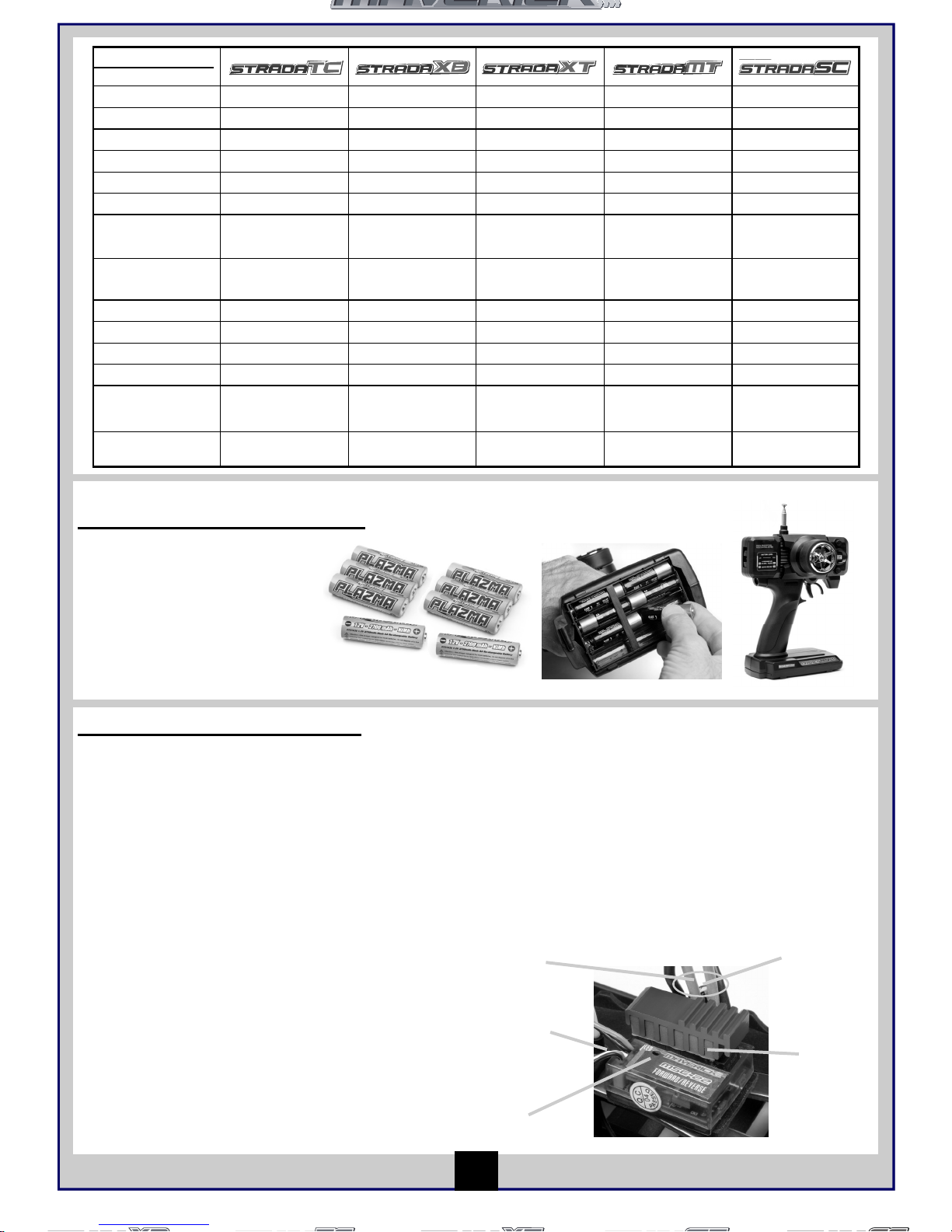
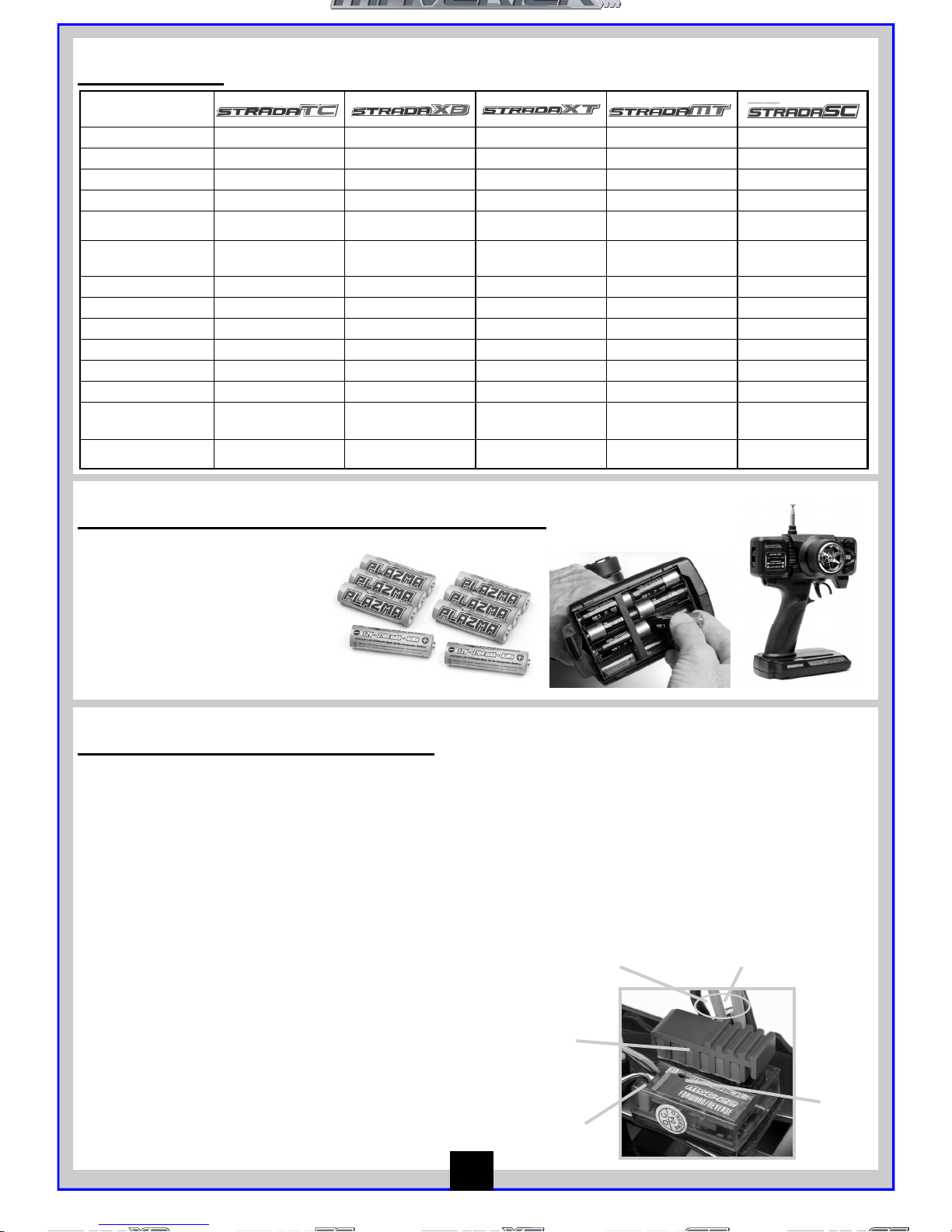
Items required for operation
8 * AA Batteries for the Transmitter
Electronic Speed Controller
Features
• 6.0Volt — 8.4Volt Power Input
• High Frequency Drive System
• Forward, Reverse & Brake Linear Operation
• Automatic Setup System
• Over Current Protection
• Thermal Protection
• Low Voltage Protection
• LED with audible beep
• 13 Turn Brushed Motor Limit
Technical Information
• PWM frequency 1.5khz (fixed)
• 200 A drive FET’s & 100A Reverse FET’s
• Case dimensions: 33mm*27mm*25mm
• Silicone Wire 14 Gauge
• Weight 4.5g with connectors and switch
• BEC Voltage 6.0V
Motor Cables
Battery
Cables
LED
Receiver Cables
FET’s
Set-Up Instructions
1. With the speed control switch set to off, plug in a suitable
battery pack.
2. With the transmitter switched on and throttle trim set to
the centre, turn on the speed control.
3. To Indicate the speed control is working correctly its LED
will flash followed by 3 beeps and a further flash.
4. If necessary adjust the throttle trim of the transmitter so
your car is stationary with no throttle or brake applied.
5. Your speed control is fully installed and ready to use.
4
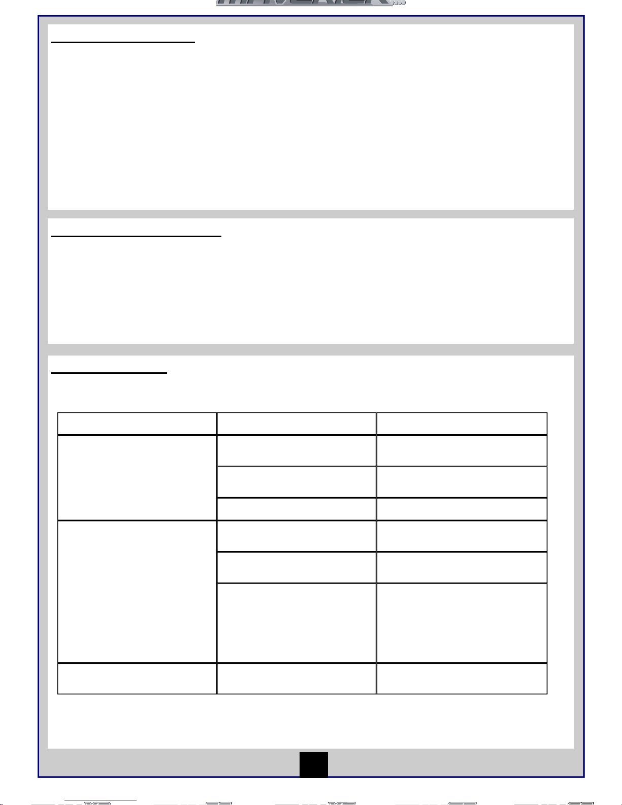
Specifications
Length
380mm 400mm 400mm 400mm 460mm
Width
200mm 250mm 300mm 310mm 250mm
Height
112mm 160mm 160mm 185mm 160mm
Wheel base
260mm 275mm 275mm 275mm 275mm
Drive System
4wd Shaft Drive 4wd Shaft Drive 4wd Shaft Drive 4wd Shaft Drive 4wd Shaft Drive
Gear Ratio
7.37:1 11.00:1 13.36:1 13.36:1 8.04:1
Ground
Clearance
4.5mm 26mm 30mm 35mm 26mm
Diameter of
wheel
65mm 86mm 105mm 118mm 86mm
Width of wheel
26mm 32mm F 40mm R 60mm 52mm 42mm
Motor
MM-22 540 size MM-22 540 size MM-22 540 size MM-22 540 size MM-22 540 size
Servo
Maverick MS-22 Maverick MS-22 Maverick MS-22 Maverick MS-22 Maverick MS-22
Receiver
MRX-22 27mhz AM MRX-22 27mhz AM MRX-22 27mhz AM MRX-22 27mhz AM MRX-22 27mhz AM
Speed Control
MSC-22 13 turn limit
Fwd/ Rev
MSC-22 13 turn
limit Fwd/Rev
MSC-22 13 turn
limit Fwd/Rev
MSC-22 13 turn limit
Fwd/Rev
MSC-22 13 turn
limit Fwd/Rev
Battery
MBP-22 1800 mAh
Ni-MH
MBP-22 1800 mAh
Ni-MH
MBP-22 1800 mAh
Ni-MH
MBP-22 1800 mAh
Ni-MH
MBP-22 1800 mAh
Ni-MH
Page 5
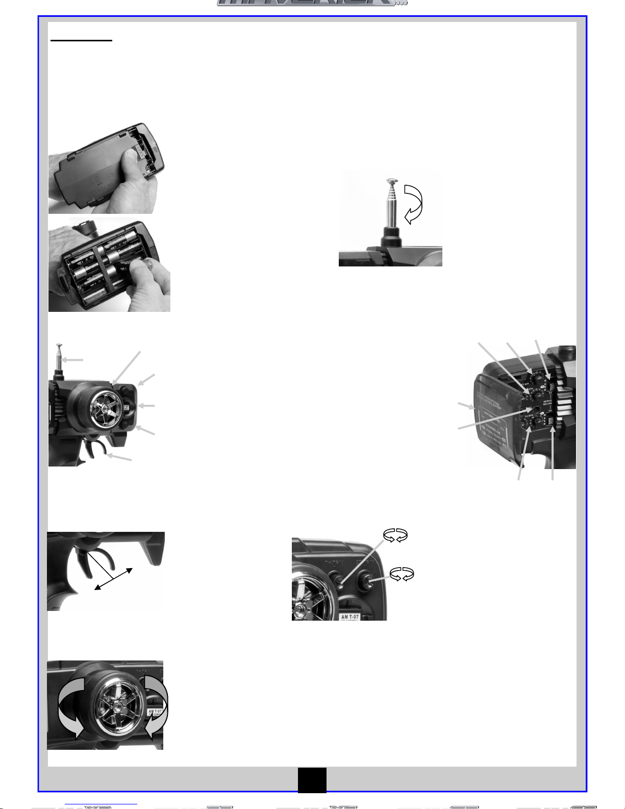
Transmitter
Preparing the transmitter
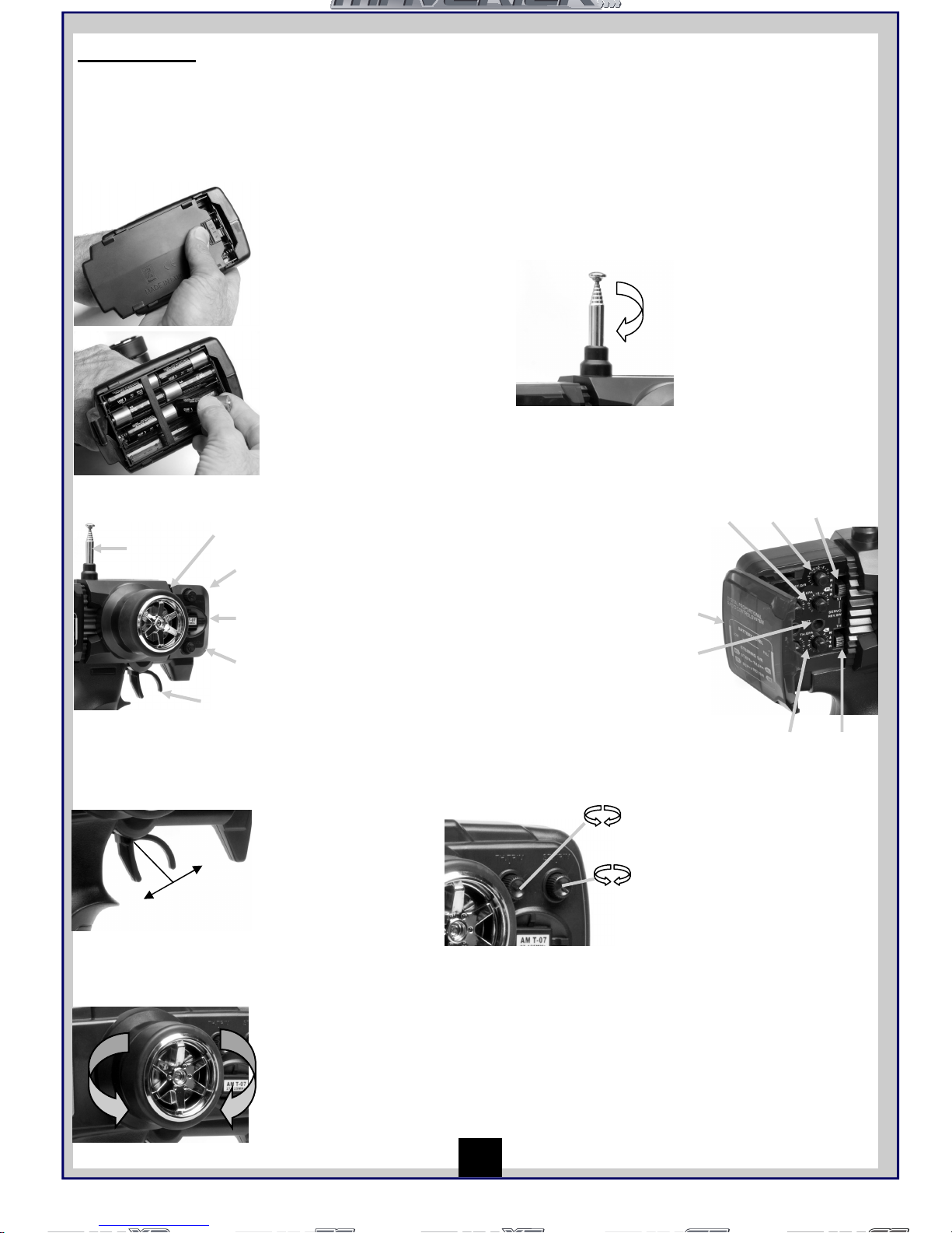
The function switches on the transmitter
1. Aerial
2. Throttle Trim
3. Steering Trim
4. Frequency Crystal
5. Throttle Trigger
6. Power Switch
7. Battery level indicator
8. Steering reverse switch
9. Throttle reverse switch
10. Steering Control (wheel)
1
8
9
7
6
10
2
3
4
5
Throttle/Steering Trim
Throttle Trim
1. Turn anti clockwise for more
brake
2. Turn clockwise for more
throttle
Steering Trim
1. Turn anti clockwise to trim to
the left
2. Turn clockwise to trim to the
right
1 2
1 2
Throttle Trigger
1. Push the trigger forward to
brake
2. Pull the trigger backwards to
go forwards and speed up
2
1
Neutral
Steering Wheel
Turn the steering wheel to the left
or right to make the go vehicle left
or right
L
R
Insert the aerial into
the hole and turn
clockwise until it is
tightly secured.
Open the battery holding
tray to expose the empty
battery slots.
Insert 8 AA batteries into
the marked spaces.
Please note the correct
direction of the batteries
Incorrect battery insertion
could lead to damage
Close the battery holding
tray to safely conceal and
secure the batteries.
Transmitter
Your Transmitter is an advanced controller designed for the beginner to be easy to use and tune. You will need to
follow the steps below to ensure you prepare the controller correctly for use and understand the adjustment
possibilities available.
Throttle/Steering Trim
1 2
1 2
5
Insert 8 AA batteries into
the marked spaces.
Please note the correct
direction of the batteries
Incorrect battery insertion
could lead to damage
Preparing the transmitter
Insert the aerial into the
hole and turn clockwise
until it is tightly secured.
Make sure you never over
extend the aerial as this
will cause it to break.
Open the battery holding
tray to expose the empty
battery slots.
1. Aerial
2. Throttle Trim
3. Steering Trim
4. Frequency Crystal
5. Throttle Trigger
6. Steering Control
(wheel)
7. Power Switch
8. Battery level
indicator
9. Steering reverse
switch
10. Throttle reverse
switch
11. Steering Throw
dial
12. Steering End
Point dials (left/
right lock)
13. Throttle End Point
dials (low/high
points)
The function switches on the transmitter
6
2
3
1
4
5
8
9
7
10
11 12
13
Throttle Trigger
Steering Wheel
2
1
Neutral
1. Push the trigger
forward to brake
2. Pull the trigger
backwards to go
forwards and
speed up
L
R
Turn the steering wheel
to the left or right to
make the go vehicle
left or right
Throttle Trim
1. Turn anti clockwise for
more brake
2. Turn clockwise for more
throttle
Steering Trim
1. Turn anti clockwise to trim
to the left
2. Turn clockwise to trim to
the right
End Point Adjustment Dials
Both steering and throttle have high point adjustments which
allows you to adjust left and right steering lock & high and low
throttle points. You can also adjust the overall lock your
vehicle has after adjusting your individual side locks.
All of these adjustment dials require an anti clockwise
movement for more and clockwise movement for less.
Page 6
Safety precautions
This product is an authentic radio controlled vehicle (RC vehicle) and it is not a toy. Read and understand this
instruction manual thoroughly before running the model. If you are not familiar with RC vehicles, we recommend that
you ask someone familiar with RC vehicles for advice.
Never connect the rechargeable drive battery in the reverse polarity or disassemble the battery. If the drive battery is
used in the wrong way, high current can be generated and it is very dangerous.
Never run RC models near people or animals, or on public streets or highways. This could cause serious accidents,
personal injuries, and/or property damage.
Recommended Tools
These tools are not included with the product but are recommended for use whilst working with this vehicle
Scissors, Mini Screwdrivers, Hexagonal Screwdrivers 1.5mm, 2.0mm, 2.5mm, 3.0mm, 4-Way Cross Wrench (Small),
4-Way Cross Wrench (Large), Side Cutters, Needle Nose Pliers
Charging the battery pack
Always use the included charger for the included battery pack. Do not use any other battery packs. Charging time for
an empty battery pack is about 6 hours. Do not charge the battery pack longer than 6 hours to avoid overheating and
battery damage.
Cautions
• This charger can be used only for the battery pack included in this kit.
• Do not charge the battery pack for longer than 6 hours. Overcharging generates excessive heat and will
damage the battery pack.
• Use the charger with adult supervision. Do not use the charger near water or when wet.
• Do not use the charger if the wire is frayed or worn. If the wire is frayed or worn a short circuit can cause a fire
or burns.
• If you are not sure about the level of the battery pack before charging use it in the vehicle until the vehicle
slows, leave to cool and then recharge.
Whilst your battery pack is charging please read the next section on driving.
6
Page 7
Driving
Driving an R/C car can be very difficult to master but here are some basic tips to help you to understand how to use it
before you have your first attempt
• Drive the vehicle in a very large space, especially until you get the feel of driving the product.
• Do not run on public streets or highways. This could cause serious accidents, personal injuries and/or property
damage.
• Do not run in water or sand.
• Make sure everyone is using different frequencies when driving together in the same area.
• If you keep pulling the throttle trigger on the transmitter, the vehicle will keep accelerating and run very fast. It
is difficult to steer the vehicle running at high speed until you become used to driving. Drive the vehicle slowly
by pulling the throttle trigger to the fullest and quickly releasing it.
You can turn the vehicle right or left while it is running.
When the vehicle is running toward you, you need to operate the steering wheel in the opposite direction to the
operation when the vehicle is running away from you.
Practice turning the vehicle, referring to the following:
Rather than just paying attention to the direction of the steering wheel, imagine that you are at the centre of the
steering wheel, looking ahead of the vehicle, to turn in the direction you like.
Once you become conformable driving the
vehicle, practice driving on a track with cones.
Keep practising until you feel comfortable with
the steering, throttle and brake at low speeds.
Once you are feeling comfortable try using
reverse.
When you have mastered the basics you will
be able to drive at higher speeds in a more
controlled fashion.
7
Page 8
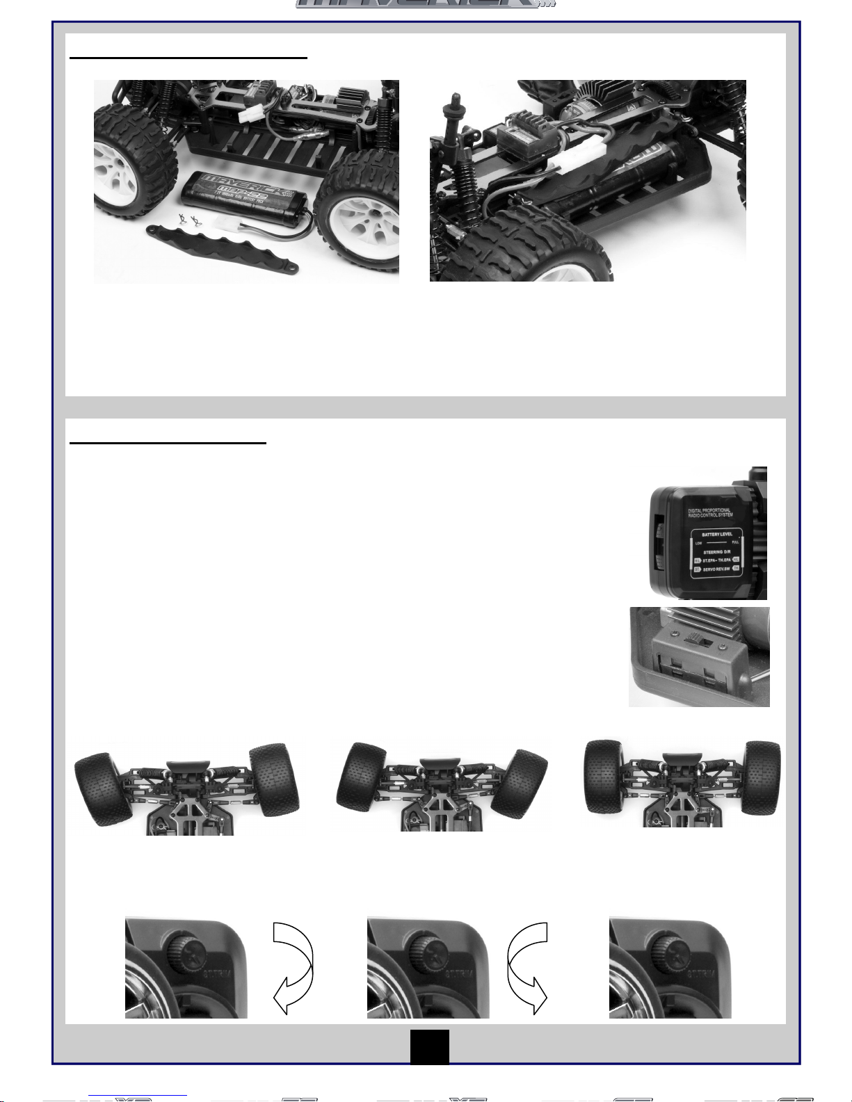
Installing the battery pack
1. You need to insert the battery pack in the
open section for the battery. Use the strap provided
to place on top of the battery and then use the 2
retaining clips to secure the battery.
2. Once fastened and secured please connect
the battery plug into the speed controller plug
noting correct polarity. Red to red, black to black.
Turning on the power
Place vehicle on block to prevent wheels from touching the ground
Turn on transmitter first and then turn on receiver.
Turn on the transmitter switch and the LED battery indicator will light up.
If it blinks or does not light up, check the polarities and battery power.
If the battery power is low, replace the batteries with new ones.
Extend the aerial to its full length.
Turn on the receiver. The automatic set-up of the factory set speed control should
have been completed. If you experience any problems with the speed control settings
refer to the Electronic Speed Control Section for correct setup information.
If the front tyres are not pointing straight forward with the transmitter on, adjust the steering
trim. Then if needed make fine adjustments with the steering trim whilst driving the vehicle.
If wheels point left, turn clockwise
If wheels point right, turn anti
clockwise.
If they point straight no
adjustment required.
8
Page 9
Turning off the power
Turn off receiver first and then turn off transmitter.
If you switch off the transmitter first before the R/C car, you may lose control of the R/C car.
• Turn off the receiver switch.
• Turn off the transmitter switch and lower the aerial.
• Disconnect the battery connector from the speed control connector.
Make sure to always turn off the power in this order (opposite order of turning on the power). If you turn off the power
in the wrong order, the vehicle may run out of control and this can be very dangerous.
Always disconnect the battery connector from the speed control connector after driving.
Maintenance after driving
Proper maintenance is very important. Make sure to always perform appropriate maintenance after driving so that
you can enjoy driving without problems next time.
Completely remove all dirt and debris from the vehicle, especially in the suspension, drive shafts and steering parts.
Inspect each part and screw for loosening, missing or damages.
You should always make sure your wheels are tight and parts move freely after and before use.
Trouble Shooting
Please read this section if you have any fault trying to operate the vehicle
If you encounter any other fault whilst operating the vehicle please contact your local hobby shop or alternatively
contact your local distributor.
9
Problem Cause Remedy
The vehicle does not move
The vehicle does not follow your
driving inputs
Transmitter or receiver is off
Batteries are not placed correctly
in the transmitter
The main battery is not charged
Transmitter or receiver is off
Transmitter or receiver aerial is
not fully extended
Some one else is using the same
frequency as you
Turn on both the transmitter and
receiver
Place batteries in the transmitter
properly
Charge the main battery
Turn on both the transmitter and
receiver
Fully extend both aerials
Change your frequency crystals to
one which no one else around you is
using or wait until the driver of the
same frequency has finished driving
or go to a different place to drive
your vehicle
The front and rear wheels rotate
in opposing directions
Incorrect user differential
placement
Insert the differential the correct way
Page 10
Tuning
Your Maverick R/C vehicle can be customised to enhance speed and performance. Simple adjustments and easily
maintained settings will assure optimum operation and performance. When making adjustments, do so only in small
increments and always check for other parts of the vehicle that are affected. Many aftermarket options are available
to make your Maverick R/C vehicle faster and stronger. Use this section as a basic tuning guide and always make
sure you write down your base settings in case you need to refer to them at a later date.
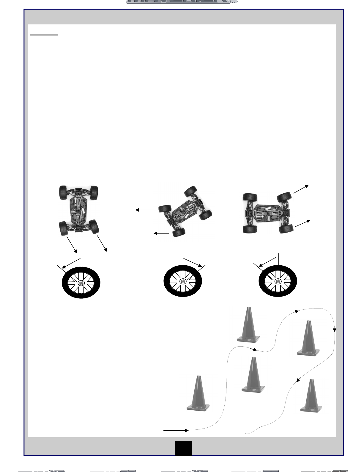
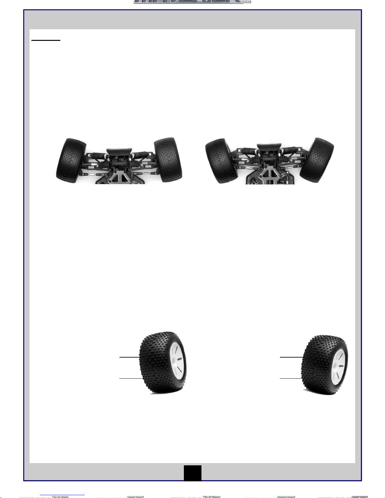
Front Steering Toe Angle
The front steering toe angle has a dramatic affect on how your car performs and how your tyres wear. You can have
toe-in, zero toe or toe-out. This can be adjusted by turning the steering turnbuckles with pliers in the direction you
need.
Toe-in will be less reactive and cause the vehicle to under steer (front wheel push straight on whilst turning). This
can be advantageous for drivers struggling to get to grips with the driving of the vehicle.
Toe-out will be more aggressive on the steering response especially on small steering inputs. This will make the car
want to over steer (rear wheels slide on small steering inputs). This is useful as a race tuning aid to gain extra
steering.
Zero toe will make the front wheels run straight and make the car very neutral. Tyre wear will also be reduced and
the vehicle will feel easier to drive.
Camber
Camber can be adjusted on all 4 wheels of the car. You can have negative camber or positive camber which will
affect the contact patch of the tyre both statically and whilst cornering. Camber is mainly used to control the wear of
the tyre. You should adjust the camber to equal the wear all across the surface of the tyre. Camber is adjusted by the
top turnbuckle linking the wheel to the chassis front and rear.
Gearing
You can adjust the gearing of the vehicle by changing the pinion gear on the motor and/or the spur gear. You should
always try to adjust your gearing so that you reach top speed two thirds of the way down the longest straight. If you
gear the vehicle too high then you may cause excessive heat and premature wear. Stick to motor manufacturers
recommendations on gear ratio.
Exaggerated Toe-In Setting (never run
this much!)
Exaggerated Toe-Out Setting (never run
this much!)
This is an example of negative
camber. This is when the top of
the wheel is closer to the centre of
the car compared to the bottom
of the wheel. Negative camber will
give more contact area in the
corner and more grip.
Excessive amounts will cause less
grip and uneven wear.
This is an example of positive
camber. This is when the bottom
of the wheel is closer to the
centre of the car compared
to the top of the wheel. Positive
camber will give less contact
area in the corner and less
grip. Excessive amounts will
cause less grip and uneven
wear.
10
Page 11

Pinion and Spur Gear Meshing
The pinion is the gear that is attached to the motor and the spur gear is attached to the drive train of the car. These
work together to make the transmission turn and drive the car. These parts will need to be correctly spaced together
(meshed) to make sure excessive wear does not occur. Once the motor is installed and the pinion gear is tight check
the mesh by trying to gently rock the spur gear with your finger (make sure no battery is connected). If you can rock
the spur gear a lot then it is too loose, alternatively if the spur gear does not rock then it is too tight. The easiest way
is to insert a thin piece of plastic (like a shopping carrier bag) between the pinion and motor before you tighten the
motor. Once tight remove the plastic carrier bag and check the mesh again. A small amount of rock should be there
on the spur gear.
Adjusting the ride height
The ride height of the chassis will greatly influence how the vehicle handles the surface it is being used on. A circuit
racing car will have less ride height (6mm) than an off road car (20mm).
Adjusting the body height
You can alter the height of your vehicles body shell. This is done by either pins/clips or screws depending on your
vehicle on the body posts. The body shells come in the optimum position as standard.
Upgrading your performance
There are many things you could choose to upgrade on an R/C vehicle to make it faster, stronger and more reliable.
Maverick cars have been designed to give you a very strong platform that is very reliable and fast enough to learn
about R/C cars in general.
You can upgrade the motor up to the speed controls limit. The Maverick MSC-22 has a 13 turn brushed motor limit
and should not be used with anything lower than a 13 turn. Optional speed control are available which have lower
motor limits. The Maverick MBP-22 1800 mAh Ni-MH battery pack can be upgraded which will give you more run
time, faster acceleration and more top speed from your vehicle.
Tyres can also be changed like real road cars. Many aftermarket options are available for different conditions but the
standard Maverick tyres have been specially chosen to meet the users needs.
There are many aspects of tuning that are too complex to describe in detail in this basic guide. You can adjust your
shock absorber oil, pistons, springs and shock position to alter how your vehicle takes the bumps. You can adjust
your roll centres to change how much grip the chassis generates in roll. You can adjust rear toe in, steering
ackerman, droop, diff tensions and types of diff to find extra performance.
Getting into racing
There is a wide network of R/C racing clubs around the world and if you feel the need for some competitive racing
then they may be the thing for you. Try doing an internet search for ‘remote controlled car racing’ and this will get you
on your way.
You should find your local model shop will be able to give you invaluable advice and support. The easiest way to find
one is by buying a specialist R/C car magazine or via looking in the telephone directory.
You can adjust the ride height on your vehicle by using the supplied black
composite spacers on the shock absorber body. The more spacers you add
the higher the chassis will sit of the ground. Make sure you add the same
amount of spacers on each side as unequal left to right ride height will result
in inconsistent performance.
You can adjust the front and rear ride height independently which will also
alter the handling characteristics. It is best to have equal front and rear ride
height.
11
Page 12
Parts Listing (For Exploded diagram see Pages 46-51)
12
Part No Description
Part No Description
Part No Description
MV22001 Shock Absorber Assembly (2Pcs)
MV22054
Countersunk Cross Head Self-Tapping Screw M3x15mm
(9Pcs)
MV22116 Shock Absorber (2Pcs)
MV22002 Dogbone 55mm (2Pcs)
MV22055 Countersunk Screw M3x10mm (8Pcs)
MV22117 Front Bumper
MV22003 Rear Bumper MV22056 Cap Head Screw M3x10mm (10pcs) MV22118 Rear Bumper
MV22004 Rear Lower Suspension Arm (2Pcs) MV22057 Round Head Screw M3x10mm (6Pcs) MV22119 Front Lower Suspension Arm (2pcs)
MV22005 Front Lower Suspension Arm (2Pcs) MV22058 Grub Screw M3x4mm (8Pcs) MV22120 Rear Lower Suspension Arm (2pcs)
MV22006 Front Top Plate MV22059 Grub Screw M4x4 (8Pcs) MV22121 Body Mount Post
MV22007 Body Post (4Pcs) MV22060 W heel Hex. (8Pcs) MV22122 Shock Tower
MV22008 Suspension Upper Arm Linkages (2Pcs) MV22061 Steeri ng Bushing (12Pcs) MV22123 Rear Lower Arm Outer Pin (2pcs)
MV22009 Rear Upright & Set Screws (2Pcs) MV22062 M3 Nylon Locknut (6Pcs) MV22124 Front Lower Arm Outer Pin (2pcs)
MV22010 Steering Hubs (2Pcs) MV22063 Body Strada TC Painted & Trimmed Red MV22125 Shock Ball Head Holder (4Pcs)
MV22011 Steering Holder (2Pcs) MV22064 Body Strada XB Painted & Trimmed Red MV22126 Domed Head Disc Screw M3x10 (8Pcs)
MV22012 Universal Joint Cup (2Pcs)
MV22065 Body Strada XT Painted & Trimmed Red
MV22127 Pin 2x10 (10Pcs)
MV22013 Suspension Reinforcement Brace (2Pcs) MV22066 Body Strada MT Painted & Trimmed Red MV22128 Bumper Post (4Pcs)
MV22014 Rear Suspension Arm Holder MV22067 Rolling Bearing 15x10x4 (6pcs) MV22129 Dogbone 89.5mm (2Pcs)
MV22015 Front Suspension Arm Holder MV22068 Rolli ng Bearing 10x5x4mm (8pcs) MV22130 Bumper Spring (4Pcs)
MV22017 Differential Main Gear MV22069 Chassis MV22131 Steering Linkage (2Pcs)
MV22018 Differential Drive Pinion MV22070 Radio Tray MV22132 Motor Pinion Gear 19T (0.6 Module)
MV22019 Differential Universal Cup Joint (2Pcs) MV22071 Centre Dogbone MV22133 Spur Gear 64T (0.6Module)
MV22020 Front Axle (2Pcs) MV22072 Spur Gear 58T (0.6 Module) MV22136
1/10 Truggy Wheel & Tyre Assembly 12mm Hex Mount
105mm Dia.x 55mm Wide
MV22021 Front Shock Tower MV22073 Motor Gear 26T (0.6 Module) MV22137 Truggy Shock Absorber (2Pcs)
MV22022 Front Suspension Lower Arm Pin Inner (2Pcs) MV22074 Chassis Top Deck MV22138 Steering Assembly
MV22023 E-clip Set (12Pcs) MV22075 Motor Mount MV22139 Front Axle (2Pcs)
MV22024 Ball Head Screw (6Pcs) MV22076 Switch Cover MV22142
MT Chrome Wheel & Tyre Assembly 115mm Dia. X
55mm Wide
MV22025 Differential Case, Seals & Washers (2Pcs) MV22077 Battery Cover Post (2pcs) MV22143 MTX-22 27MHz AM Pistol Grip 2CH Transmitter
MV22026 Rear Shock Tower MV22078 Battery Cover MV22234 Motor Gear 21T (0.6 Module)
MV22027 Gear Box Case
MV22079 Motor
MV22235 Motor Gear 25T (0.6 Module)
MV22028 Front Foam Bumper MV22080 Radio Tray Holder MV22236 Motor Gear 27T (0.6 Module)
MV22029 Body Clips (8Pcs) MV22081 Motor Gear 23T (0.6 Module) MV22237 Motor Gear 29T (0.6 Module)
MV22030 M4 Nylon Nut (8Pcs) MV22082 Gearbox Drive Shaft & E-Clip MV22238 Spur Gear Adaptor to 48/64DP Standard Spur Gears
MV22031 Antenna Pipe (4Pcs) MV22085 Motor Heatsink MV22239 Body Strada TC Painted & Trimmed Blue
MV22032 Rear Lower Arm Outer Pin (2Pcs)
MV22086 Chassis
MV22240 Body Strada XB Painted & Trimmed Blue
MV22033 Front Lower Arm Inner Pin (2Pcs) MV22087 Radio Tray MV22241 Body Strada XT Painted & Trimmed Blue
MV22034 Rear Lower Arm Inner Pin ( 2Pcs) MV22088 Centre Dogbone MV22242 Body Strada MT Painted & Trimmed Blue
MV22035 Rear Body Post Mounting Plate MV22089 Battery Corner Holder MV22243 Radio On / Off Switch
MV22036 Differential Pinions & Pin MV22091 Front Bumper MV22244 1/10 Touring Car Wheel & Tyre Assembly
MV22037 MRX-22 Receiver 27Mhz AM MV22092 Front Body Mount MV22245 MBP-22 1800 mah Ni-MH Battery Stick Pack
MV22038 Servo Arm (2Pcs) MV22093 Tail Wing post MV22246 Motor Gear 17T (0.6 Module)
MV22039 MS-22 Steering Servo MV22096 Shock Ball Head MV22247 Motor Gear 14T (0.6 Module)
MV22040 Steering Link MV22100 1/10 Buggy Chrome Front Wheel & Tyre Assembly MV22248 Shock Absorber Assembly (2Pcs)
MV22041 Steering Post Assembly MV22101 Front Lower Suspension Arm MV22249
Maverick Strada MT/TC/XB/XT Instructions & Spares
Manual
MV22042 Front Bumper Plate MV22102 Rear Lower Suspension Arm MV222050 MTX22 Transmitter Aerial
MV22043 O-Ring Seals (12Pcs) MV22103 Front Shock Plate MV22251 MSC22 Electronic Speed Controller V2
MV22044 7.2V Stick Pack Battery Charger UK 3-Pin
MV22104 Rear Shock Plate
MV22415 Front Bumper Set SC
MV22045 7.2V Stick Pack Battery Charger EU 2-Pin MV22105 Steering Linkage (2pcs) MV22416 Rear Bumper Set SC
MV22046 Round Head Screw M3x8mm (6Pcs) MV22106 Tail Wing Brace MV22417 Body Posts (4Pcs) SC
MV22047 Round Head Self-Tapping Screw M3x10mm (10Pcs) MV22107 Fr ont Lower Arm Outer Pin (2pcs) MV22418 Body Post Mount (Fr 2pcs) SC
MV22048 Round Head Screw M3x12mm (6Pcs) MV22108 Rear Lower Arm Outer Pin (2pcs) MV22419 Body Post Mount (Rr 2pcs) SC
MV22049 Round Head Screw M3x18 (4Pcs) MV22109 Wing Support (2Pcs) MV22420 Dogbone 89.5mm (2pcs)
MV22050 Round Head Screw M2x8mm (8Pcs) MV22110 Rear Wing MV22421 W heel Axle (2pcs) SC
MV22051 Round Head Screw M2x10 (10Pcs) MV22111 Dogbone Fr & Rr 80mm (2Pcs) MV22422 Wheel Hex Adaptor (4Pcs) SC
MV22052
Countersunk Cross Head Self-Tapping Screw M3x10mm
(15Pcs)
MV22112 Shock Ball End (4Pcs)
MV22423 Rear Anti-Squat Plate SC
MV22053
Countersunk Cross Head Self-Tapping Screw M3x14mm
(13Pcs)
MV22115 1/10 Buggy Chrome Rear Wheel & Tyre Assembly
MV22426 Wheel and Tyre Set (2Pcs)SC
MV22427 Ball Head Self-Tapping Screw 2.6x12mm (4Pcs)
Page 13
Sommaire
Page
Garantie 14
Garantie du composant de 90 jours 14
Non couvert par la garantie 14
Comment revendiquer votre garantie 14
Spécifications 15
Éléments obligatoires pour le fonctionnement 15
Régulateur de vitesse électronique 15
Caractéristiques 15
Information technique 15
Instructions de montage 15
Émetteur 16
Préparation de l’émetteur 16
Commandes des fonctions 16
Commande d’accélérateur 16
Roue directrice 16
Régulateur Accélération / Direction 16
Sélecteur de réglage de point limite 16
Mesures de sécurité 17
Outils recommandés 17
Charge du bloc -piles 17
Attention 17
Conduite 18
Installation du bloc -piles 19
Mise en marche 19
Arrêt 20
Entretien après la conduite 20
Dépannage 20
Accord de fréquence 21
Angle de braquage avant renforcé 21
Carrossage 21
Embrayage 21
Engrenage à roue droite et du pignon 21
Réglage du niveau du véhicule 22
Réglage de hauteur de caisse 22
Amélioration de vos résultats 22
Entrée en course 22
Liste des Pièces 23
Dessin éclaté Strada TC 46
Dessin éclaté Strada MT 47
Dessin éclaté Strada XB 48
Dessin éclaté Strada XT 49
Dessin éclaté du sous- ensemble 50
Dessin éclaté Strada SC 51
Nous savons que vous allez bien vous amuser avec votre modèle, mais pour obtenir le meilleur de votre achat,
veuillez lire cette information AVANT de le mettre en marche.
AMUSEZ-VOUS ! Mais lisez ceci d’abord !!
13
Page 14
Garantie du composant de 90 jours
Nous souhaitons que vous profitiez de votre achat, mais lisez ceci d’abord !
Ce produit est couvert par une garantie composant de 90 jours à partir de la date d’achat. Si, pendant cette période,
l’une des pièces du produit a un défaut de fabrication, nous la réparerons ou la remplacerons à notre choix.
Nous ne donnerons pas de nouvelle garantie pour une ancienne, une fois que le produit a été utilisé.
Veuillez remarquer que ce produit n’est pas un jouet, et qu’il est recommandé aux moins de 14 ans sous la
surveillance d’un adulte. Il est de la responsabilité des parents ou tuteur de garantir que les mineurs ont l’aide et la
supervision nécessaires,
Si vous pensez qu’il existe, pour toute raison, un problème avec le produit, il est de la responsabilité de l’utilisateur
de rechercher et de suivre les pas afin de corriger le problème avant de causer de plus grands dommages.
Non couvert par la garantie
Ceci est un modèle sophistiqué et de haute performance et devra être traité avec soin et respect. Tous les efforts ont
été faits pour rendre ce produit aussi fort et durable que possible, toutefois, il est possible de casser ou
d’endommager des pièces après un choc ou un usage extrême. Les composants endommagés suite à une collision,
un usage incorrect, un manque d’entretien ou des mauvais traitements ne sont pas couverts par la garantie.
Comment revendiquer votre garantie
Pour les droits de garantie, veuillez prendre d’abord contact avec votre fournisseur. Ne renvoyez pas le produit à
votre distributeur sans leur accord préalable. Vous n’avez pas à renvoyer le produit en entier, mais seulement le
composant endommagé avec une copie de votre bon d’achat. Dans beaucoup de cas, il est plus rapide et rentable
pour l’usager de monter le(s) pièce(s) de rechange sur le produit et dans ce cas, nous nous réservons le droit de ne
fournir des pièces que dans ce cas.
Tout composant retourné et inspecté par notre distributeur ne possédant pas une garantie valable, peut être sujet à
des frais d’inspection et de manipulation avant sa réexpédition. Toutes les réparations nécessaires suite à une
négligence ou mauvaise utilisation seront facturées avant le début de tout travail sur le produit. Si vous décidez de
ne réaliser aucun travail, le distributeur se réserve le droit de facturer des frais de manipulation et d’expédition.
Veuillez joindre votre preuve d’achat à ce manuel car vous pourrez en avoir besoin à l’avenir.
14
Garantie
Page 15
Spécifications
Éléments obligatoires pour le fonctionnement
8 * piles AA pour l’émetteur
Régulateur de vitesse électronique
Caractéristiques
• Entrée alimentation 6.0 Volts — 8.4Volts
• Système de conduite haute fréquence
• Marche avant, arrière et frein linéaire
Fonctionnement
• Système de configuration automatique
• Protection surintensité
• Protection thermique
• Protection basse tension
• Del avec bip sonore
• 13 Limites de tour du moteur brosse
Information technique
• Fréquence MLI 1,5 kHz (fixé)
• Entraînement TEC 200 A et TEC Arrière 100A
• Dimensions caisse : 33mm*27mm*25mm
• Jauge à fils en silicone 14
• Poids 4,5g avec connecteurs et commutateur
• Tension 6V centre électrique à bus
Câbles du moteur
Câbles bloc piles
Del
Câbles du récepteur
TEC
Instructions de montage
1. Contrôler que l’interrupteur est sur OFF lorsque
vous branchez la batterie
2. Vous allumez la radio et gardez la gâchette des
gaz au neutre. Ensuite, vous allumez le régu
lateur électronique.
3. Pour indiquer que le régulateur fonctionne correc
tement, la LED va clignoter, puis vous entendrez
3 « bip » et la LED va clignoter à nouveau.
4. Si nécessaire, ajustez le trim des gaz à votre ra
dio de manière à arrêter votre voiture au neutre.
5. Votre régulateur est réglé et prêt à être utiliser.
15
Longueur
380mm 400mm 400mm 400mm 460mm
Largeur
200mm 250mm 300mm 310mm 250mm
Hauteur
112mm 160mm 160mm 185mm 160mm
Empattement
260mm 275mm 275mm 275mm 275mm
Entraînement
4x4 Entraînement
arbre
4x4 Entraînement
arbre
4x4 Entraînement
arbre
4x4 Entraînement
arbre
4x4 Entraînement
arbre
Rapport de
vitesse
7.37:1 11.00:1 13.36:1 13.36:1 8.04:1
Garde au sol
4.5mm 26mm 30mm 35mm 26mm
Diamètre de roue
65mm 86mm 105mm 118mm 86mm
Largeur de roue
26mm 32mm Avt 40mm Arr 60mm 52mm 42mm
Moteur Taille
MM-22 540 MM-22 540 MM-22 540 MM-22 540 MM-22 540
Servo
Maverick MS-22 Maverick MS-22 Maverick MS-22 Maverick MS-22 Maverick MS-22
Récepteur
MRX-22 27mhz AM MRX-22 27mhz AM MRX-22 27mhz AM MRX-22 27mhz AM MRX-22 27mhz AM
Contrôle vitesse
MSC-22 13 limite tour
Avt /Arr
MSC-22 13 limite tour
Avt /Arr
MSC-22 13 limite tour
Avt /Arr
MSC-22 13 limite tour
Avt /Arr
MSC-22 13 limite tour
Avt /Arr
Piles
MBP-22 1800 mAh
Ni-MH
MBP-22 1800 mAh
Ni-MH
MBP-22 1800 mAh
Ni-MH
MBP-22 1800 mAh
Ni-MH
MBP-22 1800 mAh
Ni-MH
Page 16
Transmitter
Preparing the transmitter
The function switches on the transmitter
1. Aerial
2. Throttle Trim
3. Steering Trim
4. Frequency Crystal
5. Throttle Trigger
6. Power Switch
7. Battery level indicator
8. Steering reverse switch
9. Throttle reverse switch
10. Steering Control (wheel)
1
8
9
7
6
10
2
3
4
5
Throttle/Steering Trim
Throttle Trim
1. Turn anti clockwise for more
brake
2. Turn clockwise for more
throttle
Steering Trim
1. Turn anti clockwise to trim to
the left
2. Turn clockwise to trim to the
right
1 2
1 2
Throttle Trigger
1. Push the trigger forward to
brake
2. Pull the trigger backwards to
go forwards and speed up
2
1
Neutral
Steering Wheel
Turn the steering wheel to the left
or right to make the go vehicle left
or right
L
R
Insert the aerial into
the hole and turn
clockwise until it is
tightly secured.
Open the battery holding
tray to expose the empty
battery slots.
Insert 8 AA batteries into
the marked spaces.
Please note the correct
direction of the batteries
Incorrect battery insertion
could lead to damage
Close the battery holding
tray to safely conceal and
secure the batteries.
Émetteur
Votre émetteur est un régulateur avancé conçu pour faciliter l’utilisation et le réglage pour le débutant. Vous devrez
suivre les étapes ci-dessous pour vous assurer que vous avez préparé correctement le régulateur et que vous avez
compris les possibilités disponibles de réglage.
Régulateur Accélération / Direction
1 2
1 2
16
Insérez 8 piles AA dans les
espaces marqués à cet effet.
Veuillez faire attention au sens
correct des piles.
L’insertion incorrecte des piles
peut provoquer des dommages.
Préparation de l’émetteur
Insérez l’antenne dans le
trou et tournez-la à droite
jusqu’à ce qu’elle soit bien
fixe.
Assurez-vous de ne jamais
étendre l’antenne
excessivement pour ne pas
la casser.
Ouvrez la plaque de retenue des
piles pour découvrir les fentes
des piles vides.
1. Antenne
2. Régulateur d’accélérateur
3. Régulateur de direction
4. Élément piézoélectrique de
fréquence
5. Commande d’accélérateur
6. Contrôle de direction (roue)
7. Interrupteur
8. Indicateur de niveau des
piles
9. Commande de Direction
inverse
10. Commande
d’accélération inverse
11. Sélecteur de déviation
de direction
12. Sélecteur point limite de
direction (verrou gauche /
droite)
13. Sélecteur point limite
d’accélération (points
inférieur/ supérieur)
Les commandes de fonction de l’émetteur
6
2
3
1
4
5
8
9
7
10
11 12
13
Commande d’accélérateur
Roue directrice
2
1
Point mort
1. Tirez le déclencheur
vers l’avant pour freiner.
2. Tirez le déclencheur
vers l’arrière pour aller
vers l’avant et accélérer.
L
R
Tournez la roue
directrice vers la
gauche ou la droite
pour que le véhicule
aille dans cette
direction.
Régulateur d’accélérateur
1. Tournez vers la gauche pour
freiner plus fort.
2. Tournez vers la droite pour
accélérer plus fort.
Régulateur de direction
1. Tournez vers la gauche pour
orienter vers la gauche.
2. Tournez vers la droite pour
orienter vers la droite.
Sélecteur de réglage de point limite
La direction et l’accélération ont des points de réglage élevés
qui vous permettent d’ajuster le braquage de direction vers la
gauche et la droite et les points d’accélération élevés ou
faibles. Vous pouvez aussi régler le verrouillage général du
véhicule après le réglage de vos verrouillages latéraux
individuels.
Tous ces sélecteurs de réglage demande un mouvement vers
la gauche pour augmenter et un vers la droite pour diminuer.
Page 17

Mesures de sécurité
Ce produit est un vrai véhicule radiocommandé et ce n’est pas un jouet. Lisez avec attention ce manuel
d’instructions avant de mettre le modèle en marche. Si vous n’êtes pas familiarisé avec les véhicules
radiocommandés, nous vous recommandons de demander le conseil pour qui cela est familier.
Ne connectez jamais la batterie de traction rechargeable en inversant les pôles ni ne démontez la batterie. Si la
batterie de traction est utilisée en sens inverse, un courant élevé peut être engendré et cela est très dangereux.
Ne mettez jamais des modèles radiocommandés en marche près de personnes ou d’animaux, ou dans des lieux
publics. Cela peut provoquer des accidents sérieux, des blessures, et/ou des dommages matériels.
Outils recommandés
Ces outils ne sont pas fournis avec le produit mais leur utilisation est recommandée pour travailler avec ce véhicule
Ciseaux, mini tournevis, Pinces a bec effile, Tounevis hexagonaux 1.5mm, 2.0mm, 2.5mm, 3.0mm, Cle en croix
(petite), Cle en croix (grande), Pinces coupantes de cote.
Charge du bloc- piles
Utilisez toujours le chargeur fourni pour le bloc de piles fourni. N’utilisez pas d’autres blocs de piles. Le temps de
chargement pour un bloc de piles vide est d’environ 6 heures. Ne chargez pas le bloc de pile pendant plus de 6
heures pour éviter la surchauffe et l’endommagement des piles.
Attention
• Ce chargeur ne peut être utilisé que pour le bloc de piles fourni dans ce jeu.
• Ne chargez pas le bloc piles pendant plus de 6 heures. La surchauffe engendre un excès de chaleur qui
endommagera le bloc-piles.
• Utilisez le chargeur sous la supervision d’un adulte. N’utilisez pas le chargeur près de l’eau ou s’il est mouillé.
• N’utilisez pas le chargeur si le câble est effiloché ou usé. Si le câble est effiloché ou usé, un court-circuit peut
provoquer un incendie ou des flammes.
• Si vous n’êtes pas sûr du niveau du bloc –piles avant de le charger, utilisez-le dans le véhicule jusqu’à ce qu’il
ralentisse, laissez-le refroidir puis rechargez.
Pendant la charge de votre bloc-piles, veuillez lire la partie suivante sur la conduite.
17
Page 18

Conduite
La conduite d’une voiture radiocommandée peut être très difficile à maîtriser mais voici certains trucs de base pour
vous aider à comprendre comment l’utiliser avant votre première tentative.
• Conduisez le véhicule dans un endroit très grand, jusqu’à ce que vous ressentiez la conduite de ce produit.
• Ne mettez pas en marche dans des endroits ou voies publics. Cela peut provoquer des accidents sérieux, des
blessures, et/ou des dommages matériels.
• Ne faites pas marcher dans le sable ou l’eau.
• Vérifiez que chacun utilise des fréquences différentes pour conduire ensemble dans un même endroit.
• Si vous maintenez le déclencheur d’accélération de l’émetteur, le véhicule accélérera de plus en plus et ira
très vite. Il est difficile de manœuvrer le véhicule à grande vitesse jusqu’à ce que vous utilisiez l’entraînement.
Conduisez doucement le véhicule en tirant le déclencheur d’accélération à fond et en le relâchant aussitôt.
Vous pouvez faire tourner le véhicule à droite ou à gauche pendant son fonctionnement.
Lorsque le véhicule avance vers vous, vous devez mettre la roue directrice en sens inverse à sa marche lorsque il
s’éloigne de vous.
Exercez-vous à faire virer le véhicule en vous reportant à ce qui suit :
Plutôt que de ne prêter attention qu’au sens de la roue directrice, imaginez que vous êtes au centre de la roue
directrice, en regardant face au véhicule pour tourner dans le sens que vous souhaitez.
Une fois que vous vous sentez à l’aise pour
conduire le véhicule, exercez-vous à conduire
sur une piste avec des cônes.
Continuez à pratiquer jusqu’à ce que vous
vous sentiez à l’aise avec la direction,
l’accélération et le frein à de basses vitesses.
Une fois que vous êtes à l’aise, essayez en
marche arrière.
Lorsque vous maîtrisez les bases, vous serez
capable de conduire à de plus grandes
vitesses d’un mode contrôlé.
18
Page 19

19
Installation du bloc -piles
1. Vous devez insérer le bloc-piles dans la partie
ouverte de la batterie. Utilisez la barrette fournie
pour mettre sur les piles, puis utilisez les deux
agrafes de retenue pour assurer les piles.
2. Une fois serrée et assurée, veuillez connecter la
fiche de la batterie dans la fiche du régulateur de
vitesse Vérifiez l’exactitude de la polarité. Rouge
avec rouge, noir avec noir.
Mise en marche
Posez le véhicule sur le bloc pour éviter que les roues ne touchent le sol
Allumez d’abord l’émetteur puis le récepteur.
Allumez l’émetteur et l’indicateur de batterie Del s’allume.
S’il clignote ou ne s’allume pas, vérifiez les polarités et l’alimentation des piles.
Si l’énergie des piles est faible, remplacez les piles par des neuves.
Sortez l’antenne à sa longueur maximale.
Allumez le récepteur. La configuration automatique du contrôle de vitesse ajusté en usine
devra être finie. Si vous rencontrez des problèmes avec les paramètres de contrôle de la
vitesse, reportez-vous à la partie de Contrôle de vitesse électronique pour une information
adéquate de configuration.
Si les pneus avant ne sont pas orientés vers l’avant avec l’émetteur en marche, ajustez le
régulateur de direction. Puis au besoin, effectuez des réglages plus précis avec le régulateur
de direction tout en conduisant le véhicule.
Si les roues vont vers la gauche,
tournez à droite.
Si les roues vont vers la droite,
tournez à gauche.
Si elles vont tout droit, aucun
réglage n’est à réaliser.
Page 20

Arrêt
Éteignez d’abord le récepteur puis l’émetteur.
Si vous éteignez l’émetteur avant la voiture radiocommandée, vous pouvez perdre le contrôle de la voiture.
• Éteignez l’interrupteur du récepteur.
• Éteignez l’interrupteur de l’émetteur et baissez l’antenne.
• Déconnectez le connecteur des piles du connecteur de contrôle de vitesse.
Vérifiez d’éteindre toujours l’alimentation dans cet ordre (ordre inverse d’allumage). Si vous éteignez l’alimentation
dans l’ordre incorrect, le véhicule peut avancer sans contrôle et cela peut s’avérer très dangereux.
Déconnectez toujours le connecteur des piles du connecteur de contrôle de vitesse après avoir conduit.
Entretien après la conduite
Un entretien adéquat est très important. Réalisez toujours un entretien adéquat après la conduite pour que vous
puissiez profiter de la conduite sans aucun problème la fois suivante.
Enlevez complètement toute saleté et tout débris du véhicule, surtout des suspensions, des arbres de transmission
et des pièces de direction. Inspectez chaque pièce et vis contre tout desserrement, absence ou dommages.
Vous devrez toujours vérifier que vos roues sont bien serrées et que les pièces possèdent un mouvement libre avant
et après chaque utilisation.
Dépannage
Veuillez lire cette partie si vous rencontrez un défaut en essayant de faire marcher votre véhicule.
Si vous rencontrez un autre défaut lors du fonctionnement du véhicule, veuillez prendre contact avec votre magasin
de modélisme local ou avec notre distributeur local.
20
Problème Cause Solution
Le véhicule ne bouge pas
Le véhicule ne suit pas vos
commandes de conduite
L’émetteur ou le récepteur est
éteint
Les piles ne sont pas correctement installées dans l’émetteur
La batterie principale n’est pas
assez chargée
L’émetteur ou le récepteur est
éteint
L’antenne de l’émetteur ou du
récepteur n’est pas complètement
sortie
Une autre personne utilise la
même fréquence que vous
Allumez l’émetteur et le récepteur
Mettez correctement les piles dans
l’émetteur
Chargez la batterie principale
Allumez l’émetteur et le récepteur
Sortez complètement les deux
antennes
Changez vos éléments piézo
électriques de fréquence à un que
personne d’autre n’utilise ou
attendez que le conducteur de la
même fréquence ait fini de conduire
ou allez à un autre endroit pour
conduire votre véhicule
Les roues avant et arrière
tournent dans des directions
opposées
Emplacement différentiel de
l’usager incorrect
Insérez dans le bon sens le
différentiel
Page 21

Accord de fréquence
Votre véhicule radiocommandé Maverick peut être personnalisé afin d’augmenter la vitesse et la performance. Des
réglages simples et des paramètres conservés facilement garantissent un fonctionnement et une performance
optimaux. Lors des réglages, ne réalisez que de petites augmentations et vérifiez toujours si le reste des parties du
véhicule a été affecté. Beaucoup d’options du marché des pièces de rechange sont disponibles pour rendre votre
véhicule radiocommandé Maverick plus rapide et résistant. Utilisez cette partie comme guide de réglage basique et
notez toujours vos paramètres de base au cas où vous auriez besoin de vous y rapporter dans le futur.
Angle de braquage avant renforcé
L’angle de braquage avant renforcé affecte gravement la façon dont votre voiture fonctionne et l’usure des pneus.
Vous pouvez avoir un pincement, une ouverture ou aucun écart. Cela peut s’ajuster en tournant les tendeurs de
direction avec des pinces dans la direction nécessaire.
Le pincement sera moins réactif et provoquera que le véhicule sous-vire (la roue avant va tout droit lors d’un virage)
Cela peut aider les pilotes qui se battent pour prendre le dessus sur la conduite du véhicule.
L’ouverture sera plus agressive pour la réponse de direction surtout pour les petites commandes de direction. Cela
fera que le véhicule survire (les roues arrières glissent avec de petites commandes de direction.) Cela est utile en
course pour gagner plus de direction.
Aucun parallélisme fera que les roues avant iront tout droit et que la voiture restera neutre. L’usure des pneus sera
aussi réduite et le véhicule sera plus facile à diriger.
Carrossage
Le carrossage peut être réglé sur les 4 roues de la voiture. Vous pouvez avoir un carrossage négatif ou positif ce qui
affecte l’aire de contact des pneus statiquement et pendant la dérive. Le carrossage est surtout utilisé pour contrôler
l’usure des pneus. Vous devez régler le carrossage pour égaliser l’usure de la surface du pneu. Le carrossage est
réglé par le tendeur supérieur qui relie la roue au châssis avant et arrière.
Embrayage
Vous pouvez régler l’embrayage du véhicule en changeant l’entraînement du pignon du moteur et/ou la roue droite.
Vous devez toujours essayer de régler votre embrayage pour atteindre une vitesse de pointe des deux tiers en
descente de la plus grande ligne droite. Si vous forcez de trop le véhicule, vous pouvez provoquer un excès de
chaleur et une usure prématurée. Collez les recommandations des fabricants du moteur sur rapport de boîte.
Paramètre de pincement exagéré (Ne
pas le faire souvent!)
Paramètre d’ouverture exagéré (Ne pas le
faire souvent!)
Ceci est un exemple de carrossage négatif. C’est lorsque le haut
de la roue est près du centre de la
voiture, par rapport au bas de la
roue. Le carrossage négatif offrira
une aire de contact plus grande
dans le virage et plus d’adhérence. Des quantités excessives provoqueront une adhérence inférieure et une usure
inégale.
Ceci est un exemple de
carrossage positif. C’est lorsque
le bas de la roue est près du
centre de la voiture, par rapport
au haut de la roue. Le
carrossage positif offrira une
aire de contact plus petite dans
le virage et moins d’adhérence.
Des quantités excessives
provoqueront une adhérence
inférieure et une usure inégale.
21
Page 22

Engrenage à roue droite et du pignon
Le pignon est l’engrenage qui est attaché au moteur et la roue droite est attachée à la transmission de la voiture. Ils
travaillent ensemble pour faire tourner la transmission et entraîner la voiture. Ces pièces devront être espacées
correctement (emboîtées) pour s’assurer qu’une usure excessive ne se produise pas. Une fois le moteur installé et
l’engrenage à pignon ajusté, vérifiez l’emboîtement en essayant de faire rouler doucement la roue droite avec votre
doigt (vérifiez que la batterie n’est pas connectée). Si vous pouvez beaucoup déplacer la roue droite, c’est qu’elle est
trop lâche, et inversement si vous ne le pouvez pas. La manière la plus facile est d’insérer une fine pièce de
plastique (comme un sac de course) entre le pignon et le moteur avant d’ajuster le moteur. Une fois ajustée, enlevez
le sac de course et vérifiez l’emboîtement. Un léger basculement devra rester dans la roue droite.
Réglage du niveau du véhicule
La hauteur du châssis aura une grande influence sur la manière dont se déplace le véhicule sur la surface où il
circule. Une voiture de course aura moins de hauteur (6mm) qu’une voiture tout terrain (20mm).
Réglage de hauteur de caisse
Vous pouvez modifier la hauteur de caisse de vos véhicules. Cela se fait par des agrafes/ attaches ou des vis selon
votre véhicule monté sur la caisse. Les caisses standard viennent en position optimale.
Amélioration de vos résultats
Il existe beaucoup de choses que vous pouvez choisir pour actualiser votre véhicule radiocommandé afin de le
rendre plus rapide, plus résistant et plus fiable. Les voitures Maverick ont été conçues pour vous offrir une
plateforme très forte, qui est très fiable et assez rapide pour apprendre le B.A Bâ des voitures radiocommandées en
général.
Vous pouvez actualiser le moteur jusqu’à la limite des contrôles de vitesse. La Maverick MSC-22 possède une limite
de 13 tours de brosse à moteur et ne pourra être utilisée avec rien d’autre inférieur à 13 tours. Des contrôles de
vitesse optionnels sont disponibles avec des limites de régime inférieures. Le bloc-piles Ni-MH de 1800 mAh de la
Maverick MBP-22 peut être actualisé ce qui vous offre plus de temps, une meilleure accélération et une vitesse de
pointe supérieure pour votre véhicule.
Les pneus peuvent aussi être changés comme ceux des voitures réelles. Beaucoup d’options du marché
d’occasions sont disponibles sous différentes conditions, mais les pneus standard de Maverick ont été spécialement
choisis pour réunir les exigences des usagers.
Il y a beaucoup d’aspects du réglage qui sont trop compliqués pour être expliqué avec précision dans ce guide de
base. Vous pouvez ajuster l’huile des amortisseurs, les pistons, les ressorts et la position d’amortissement pour
altérer la manière dont votre véhicule reçoit les secousses. Vous pouvez ajuster vos centres de roulement pour
modifier l’adhérence que le châssis engendre en roulant. Vous pouvez ajuster le pincement arrière, la direction
Ackerman, la chute, les tensions de diff. et ses types pour rechercher un rendement extra.
Entrée en course
Il existe un grand réseau de clubs de course de véhicules radiocommandés dans le monde entier et si vous avez
envie de faire des courses de compétition, ces clubs peuvent être faits pour vous. Essayez de faire une recherche
par Internet au sujet de « course de voiture téléguidée » et cela vous mettra sur le chemin.
Vous verrez que votre magasin de modélisme vous offrira un conseil et une aide de grande valeur. La manière la
plus facile d’en trouver un est d’acheter une revue de voiture radiocommandée ou en cherchant dans l’annuaire
téléphonique.
Vous pouvez régler le niveau du véhicule grâce aux cales en composite noir
fournies sur les amortisseurs de carrosserie. Plus vous ajoutez de cales, plus
haut se retrouvera le châssis par rapport au sol. Vérifiez que vous ajoutez la
même quantité de cales de chaque côté car un déséquilibre de niveau entre
la gauche et la droite provoquerait un mauvais rendement.
Vous pouvez régler le niveau avant et arrière du véhicule de manière
indépendante ce qui altère aussi les caractéristiques de maniement. Il est
recommandé d’avoir un niveau de véhicule égalisé.
22
Page 23

Liste des Pièces (Pour le diagramme éclaté voir les pages 46-51)
23
Numéro de
pièce
Description
Numéro de
pièce
Description
Numéro de
pièce
Description
MV22001 Amortisseur (2 pièces) MV22054
Vis auto taraudeuse cruciforme à tête plate M3x15mm
(x9)
MV22116 Amortisseur (2 pièces)
MV22002 Bobine 55 mm (2 pièces)
MV22055 Vis à tête plate M3 x10mm (x8)
MV22117 Pare-choc avant
MV22003 Pare-choc arrière
MV22056 Vis à tête M3x10mm (x10)
MV22118 Pare-choc arrière
MV22004 Bras de suspension inférieur arrière (x 2)
MV22057 Vis à tête ronde M3 x 10mm (x6)
MV22119 Bras de suspension inférieur avant (x 2)
MV22005 Bras de suspension inférieur avant (x 2)
MV22058 Vis sans tête M3 x4mm (x8)
MV22120 Bras de suspension inférieur arrière (x 2)
MV22006 Tôle supérieure avant
MV22059 Vis sans tête M4 x4mm (x8)
MV22121 Montant carrosserie
MV22007 Montant caisse (x4)
MV22060 Hex. roue (x8)
MV22122 Tour isolante
MV22008 Transmissions bras supérieur de suspension (x2)
MV22061 Douille de direction (x12)
MV22123 Axe extérieur du bras inférieur arrière (x 2)
MV22009 Montant arrière et Vis de blocage (x 2)
MV22062 Contre-écrou nylon M3 (x6)
MV22124 Axe extérieur du bras inférieur avant (x 2)
MV22010 Moyeux de direction (x2)
MV22063 Caisse Strada TC peinte et rayée Rouge
MV22125 Porte tête à bille amortisseur (x4)
MV22011 Bloque –volant de direction (x2)
MV22064 Caisse Strada XB peinte et rayée Rouge
MV22126 Vis disque tête à dôme M3x10 (x8)
MV22012 Coupelle du cardan (x2)
MV22065 Caisse Strada XT peinte et rayée Rouge
MV22127 Axe 2x10 (x10)
MV22013 Renfort de suspension (x2)
MV22066 Caisse Strada MT peinte et rayée Rouge
MV22128 Montant pare-choc (x4)
MV22014 Support du bras de suspension arrière
MV22067 Roulement 15x10x4 (x6)
MV22129 Bobine 89,5mm (2 pièces)
MV22015 Support du bras de suspension avant
MV22068 Roulement 10x5x4mm (x8)
MV22130 Ressort pare-choc (x4)
MV22017 Boîte principale de différentiel
MV22069 Châssis
MV22131 Tringlerie de direction (x2)
MV22018 Satellite de différentiel
MV22070 Tiroir radio
MV22132 Engrenage à pignon du moteur 19T (Module 0,6)
MV22019 Coupelle du cardan différentiel (x2)
MV22071 Bobine centre
MV22133 Roue droite 64T (Module 0,6)
MV22020 Essieu avant (x2) MV22072 Roue droite 58T (Module 0,6) MV22136
Pneu et roue Truggy 1/10 12mm Mont. hex. 105mm Dia
Largeur 55mm
MV22021 Tour isolante avant
MV22073 Roue droite 26T (Module 0,6)
MV22137 Amortisseur Truggy (2 pièces)
MV22022 Axe intérieur du bras de suspension inférieur avant (x 2) MV22074 Plancher du châssis MV22138 Direction
MV22023 Ensemble d’attache en E (x12) MV22075 Montage moteur MV22139 Essieu avant (x2)
MV22024 Tête de vis à bille (x6)
MV22076 Protège interrupteur
MV22142
Pneu et roue chromés MT 115 mm Dia X largeur 55
mm
MV22025 Boîtier différentiel, Joints et Rondelles (x2) MV22077 Montant couvercle piles (x2) MV22143 Émetteur 2 canaux Poignée pistolet MTX-22 27MHz AM
MV22026 Tour isolante arrière
MV22078 Couvercle piles
MV22234 Boîtier moteur 21T (Module 0,6)
MV22027 Carter
MV22079 Moteur
MV22235 Boîtier moteur 25T (Module 0,6)
MV22028 Pare-choc avant en mousse
MV22080 Porte tiroir radio
MV22236 Roue droite 27T (Module 0,6)
MV22029 Agrafes carrosserie (x8)
MV22081 Boîtier moteur 23T (Module 0,6)
MV22237 Roue droite 29T (Module 0,6)
MV22030 Écrou nylon M4 (x8) MV22082 Arbre de transmission boîtier de vitesse et attache-E MV22238
Adaptateur roue droite pour Roues droites standard 48
DP
MV22031 Conduit antenne (x4)
MV22085 Radiateur moteur
MV22239 Caisse Strada TC peinte et rayée Bleue
MV22032 Axe extérieur du bras inférieur arrière (x 2)
MV22086 Châssis
MV22240 Caisse Strada XB peinte et rayée bleue
MV22033 Axe intérieur du bras inférieur avant (x 2)
MV22087 Tiroir radio
MV22241 Caisse Strada XT peinte et rayée bleue
MV22034 Axe intérieur du bras inférieur arrière (x 2)
MV22088 Bobine centre
MV22242 Caisse Strada MT peinte et rayée bleue
MV22035 Plaque de fixation de montant de caisse arrière MV22089 Support en dièdre des piles MV22243 Bouton marche /arrêt acheté comme pièce de MV22083
MV22036 Pignons différentiel et Axe
MV22091 Pare-choc avant
MV22244 Pneu et roue Strada TC
MV22037 Récepteur MRX-22 27Mhz AM
MV22092 Carrosserie avant
MV22245 Remplacer par NR99105 ou semblable
MV22038 Bras de servo (x2) MV22093 Montant aile arrière MV22246 Roue droite 17T (Module 0,6)
MV22039 Servo de direction MS-22 MV22096 Tête à bille d’amortisseur MV22247 Roue droite 14T (Module 0,6)
MV22040 Articulation de direction MV22100 Pneu et roue avant chromée Buggy 1/10 MV22248 Amortisseur (2 pièces)
MV22041 Montant direction MV22101 Bras de suspension inférieur avant MV22249 Maverick Strada MT/TC/XB/XT Insructions
MV22042 Plaque pare-choc avant MV22102 Bras de suspension inférieur arrière MV222050 Antenne d'émetteur
MV22043 Joints toriques (x12) MV22103 Plaque amortisseur avant MV22251 MS22 Régulateur de vitesse électronique
MV22044 Chargeur bloc piles en bâton de 7,2V 3 broches GB
MV22104 Plaque amortisseur arrière
MV22415
Ensemble de pare-choc avant SC
MV22045 Chargeur bloc piles en bâton de 7,2V 2 broches EU
MV22105 Tringlerie de direction (x2)
MV22416
Ensemble de pare-choc arrière SC
MV22046 Vis à tête ronde M3 x8mm (x6)
MV22106 Renfort aile arrière
MV22417 Montants de carrosserie (4 pièces) SC
MV22047 Vis auto taraudeuse à tête ronde M3x10mm (x10)
MV22107 Axe extérieur du bras inférieur avant (x 2)
MV22418 Monture de montant de carrosserie (Av 2 pièces) SC
MV22048 Vis à tête ronde M3 x 12mm (x6)
MV22108 Axe extérieur du bras inférieur arrière (x 2)
MV22419 Monture de montant de carrosserie (Ar 2 pièces) SC
MV22049 Vis à tête ronde M3 x 18mm (x4)
MV22109 Support aile (x2)
MV22420 Bobine 89,5 mm (2 pièces)
MV22050 Vis à tête ronde M2 x8mm (x8)
MV22110 Aile arrière
MV22421 Essieu de roue (2 pièces) SC
MV22051 Vis à tête ronde M2 x 10mm (x10)
MV22111 Bobine avt et arr. 80mm (x2)
MV22422 Adaptation hexagonale de roue (4 pièces) SC
MV22052
Vis auto taraudeuse cruciforme à tête plate M3x10mm
(x15)
MV22112 Extrémité à bille amortisseur (x4) MV22423 Platine arrière d'anticabrage SC
MV22053
Vis auto taraudeuse cruciforme à tête plate M3x14mm
(x13)
MV22115 Pneu et roue arrière chromée Buggy 1/10 MV22426 Ensemble de jante et pneu (2 pièces)SC
MV22427
Vis autotaraudeuse à rotule 2,6x12mm (4 pièces)
Page 24

Inhaltsverzeichnis
Seite
Garantie 25
90-Tage-Garantie auf Komponenten 25
Von der Garantie nicht gedeckt 25
Garantieansprüche geltend machen 25
Technische Daten 26
Für den Betrieb erforderlich 26
Elektronischer Geschwindigkeitsregler 26
Merkmale 26
Technische Informationen 26
Anweisungen zum Einrichten 26
Sender 27
Vorbereiten des Senders 27
Funktionsschalter 27
Gashebel 27
Lenkrad 27
Gas-/Lenkungsversatz 27
Endpunktregelung 27
Sicherheitsmaßnahmen 28
Empfohlenes Werkzeug 28
Batteriepack aufladen 28
Vorsichtshinweise 28
Fahren 29
Batteriepack einsetzen 30
Stromversorgung einschalten 30
Stromversorgung ausschalten 31
Wartung und Pflege nach dem Fahren 31
Fehlersuche 31
Tuning 32
Vorderrad-Vorspur 32
Radsturz 32
Getriebe 32
Ritzel- und Stirnrad-Eingriff 33
Bodenfreiheit einstellen 33
Karosseriehöhe einstellen 33
Leistung steigern 33
Rennmodus 33
Teileliste 34
Strada TC Explosionszeichnung 46
Strada MT Explosionszeichnung 47
Strada XB Explosionszeichnung 48
Strada XT Explosionszeichnung 49
Unterbaugruppen Explosionszeichnung 50
Strada SC Explosionszeichnung 51
Wir wissen, dass Sie mit Ihrem Modell viel Spaß haben weden, aber BEVOR Sie das Modell in Betrieb nehmen,
lesen Sie bitte erst diese Informationen, damit Sie das Beste aus Ihrem Kauf machen können.
VIEL SPASS! Aber lesen Sie bitte erst diese Anleitung !!
24
Page 25

90-Tage-Garantie auf Komponenten
Wir möchten, dass Sie an Ihrem Modell Spaß haben - aber lesen Sie bitte erst die nachstehenden
Ausführungen!
Für dieses Produkt gilt eine 90-Tage-Garantie auf Komponenten ab dem Kaufdatum. Wenn während dieser Zeit ein
Teil des Produkts infolge Fabrikationsmängeln ausfallen sollte, liegt es in unsrem Ermessen, ob wir das Teil
reparieren oder austauschen.
Wenn das Produkt einmal benutzt wurde, bieten wir keine Neu-für-Alt-Garantie.
Beachten Sie bitte, dass dieses Produkt kein Spielzeug ist und dass Kinder unter 14 Jahren von einem
Erwachsenen beaufsichtigt werden sollten. Es liegt in der Verantwortung der Eltern oder Aufsichtspersonen,
sicherzustellen, dass Minderjährige entsprechende Anleitung und Aufsicht erhalten.
Bei der Vermutung eines Problems mit dem Produkt, aus welchem Grunde auch immer, ist der Benutzer dafür
verantwortlich, das Problem zu untersuchen und für Abhilfe zu sorgen, bevor weitere Schäden entstehen.
Von der Garantie nicht gedeckt
Dies ist ein technisch ausgereiftes Hochleistungs-Modell, das mit Sorgfalt und Respekt behandelt werden sollte. Wir
haben zwar alles getan, um dieses Produkt so stabil und haltbar wie nur möglich zu machen, trotzdem können auf
Grund der Natur dieses Produkts Teile bei Zusammenstößen oder extremem Einsatz beschädigt werden oder
brechen. Komponenten, die durch einen Unfall, falsche Verwendung, mangelnde Wartung und Pflege oder
Mißbrauch beschädigt wurden, fallen nicht unter die Garantie.
Garantieansprüche geltend machen
Mit Garantieansprüchen wenden Sie sich bitte zuerst an Ihren Händler. Ohne vorherige Genehmigung das Produkt
nicht an den Distributor einschicken. Sie brauchen das Produkt nicht als Ganzes einschicken, nur die beschädigte
Komponente zusammen mit einer Kopie des Kaufbelegs. In vielen Fällen ist es für Sie schneller und
kostengünstiger, Ersatzteile in das Produkt einzubauen; daher behalten wir uns das Recht vor, nur in solchen Fällen
die Ersatzteile zu liefern.
Für jede eingeschickte Komponente, bei deren Überprüfung Ihr Distributor einen ungültigen Garantieanspruch
festgestellt hat, werden Ihnen vor der Rücksendung möglicherweise Prüfungs- und Bearbeitungskosten in Rechnung
gestellt. Reparaturen, die als Folge von Nachlässigkeit oder Mißbrauch erforderlich sind, werden in Rechnung
gestellt, bevor Arbeiten am Produkt durchgeführt werden. Wenn Sie sich entscheiden, dass keine Arbeiten
ausgeführt werden sollen, hat der Distributor das Recht, Bearbeitungs- und Versandkosten in Rechnung zu stellen.
Sie sollten Ihren Kaufbeleg an dieses Handbuch anheften, für den Fall, dass Sie ihn später noch einmal benötigen.
25
Garantie
Page 26

Technische Daten
Für den Betrieb erforderlich
8 * AA Batterien für den Sender
Del
Elektronischer Geschwindigkeitsregler
Merkmale
• 6,0Volt — 8,4Volt Speisespannung
• Hochfrequenz-Antriebssystem
• Vorwärts, Rückwärts & Bremse Linear Betrieb
• Automatisch Einrichtsystem
• Überstromschutz
• Überhitzungsschutz
• Unterspannungsschutz
• LED mit hörbarem Signal
• 13 Wckl. Bürstenmotorgrenze
Technische Informationen
• PWM Frequenz 1,5 kHz (fest)
• 200 A Antrieb FET’s & 100A Rückwärts FET’s
• Gehäuseabmessungen: 33mm*27mm*25mm
• Silikondraht Nr. 14
• Gewicht 4,5 g mit Steckern und Schalter
• BEC Spannung 6,0 V
Motorkabel
Batteriekabel
Empfängerkabel
FET’s
Anweisungen zum Einrichten
1. Stellen Sie den Schalter auf Off-Position und
schließen Sie einen geladenen Akkupack an.
2. Schalten Sie die Fernsteuerung ein und achten Sie
darauf, dass die Gastrimmung auf 0 steht.
Schalten Sie den Regler ein.
3. Um die korrekte Funktion des Reglers anzuzeigen,
blinkt eine LED auf, gefolgt von 3 Pieptönen und
einem weiteren Blinken der LED.
4. Justieren Sie die Trimmung Ihrer Fernsteuerung, so
dass weder ein Gas- noch ein Bremsbefehl in
Nullstellung ausgeführt wird.
5. Ihr Regler ist nun vollständig eingestellt und fahrbereit.
26
LED
Länge
380mm 400mm 400mm 400mm 460mm
Breite
200mm 250mm 300mm 310mm 250mm
Höhe
112mm 160mm 160mm 185mm 160mm
Radstand
260mm 275mm 275mm 275mm 275mm
Antriebssystem
Allrad-Wellenantrieb Allrad-Wellenantrieb Allrad-Wellenantrieb Allrad-Wellenantrieb Allrad-Wellenantrieb
Übersetzungsverhältnis
7.37:1 11.00:1 13.36:1 13.39:1 8.04:1
Bodenfreiheit
4.5mm 26mm 30mm 35mm 26mm
Raddurchmesser
65mm 86mm 105mm 118mm 86mm
Reifenbreite
26mm 32mm V 40mm H 60mm 52mm 42mm
Motor Größe
MM-22 540 MM-22 540 MM-22 540 MM-22 540 MM-22 540
Servo
Maverick MS-22 Maverick MS-22 Maverick MS-22 Maverick MS-22 Maverick MS-22
Empfänger
MRX-22 27mhz AM MRX-22 27mhz AM MRX-22 27mhz AM MRX-22 27mhz AM MRX-22 27mhz AM
Geschwindigkeitsregler
MSC-22 13 Wckl.
Anschlag Vw/ Rw
MSC-22 13 Wckl.
Anschlag Vw/ Rw
MSC-22 13 Wckl.
Anschlag Vw/ Rw
MSC-22 13 Wckl.
Anschlag Vw/ Rw
MSC-22 13 Wckl.
Anschlag Vw/ Rw
Batterie
MBP-22 1800 mAh
Ni-MH
MBP-22 1800 mAh
Ni-MH
MBP-22 1800 mAh
Ni-MH
MBP-22 1800 mAh
Ni-MH
MBP-22 1800 mAh
Ni-MH
Page 27

Transmitter
Preparing the transmitter
The function switches on the transmitter
1. Aerial
2. Throttle Trim
3. Steering Trim
4. Frequency Crystal
5. Throttle Trigger
6. Power Switch
7. Battery level indicator
8. Steering reverse switch
9. Throttle reverse switch
10. Steering Control (wheel)
1
8
9
7
6
10
2
3
4
5
Throttle/Steering Trim
Throttle Trim
1. Turn anti clockwise for more
brake
2. Turn clockwise for more
throttle
Steering Trim
1. Turn anti clockwise to trim to
the left
2. Turn clockwise to trim to the
right
1 2
1 2
Throttle Trigger
1. Push the trigger forward to
brake
2. Pull the trigger backwards to
go forwards and speed up
2
1
Neutral
Steering Wheel
Turn the steering wheel to the left
or right to make the go vehicle left
or right
L
R
Insert the aerial into
the hole and turn
clockwise until it is
tightly secured.
Open the battery holding
tray to expose the empty
battery slots.
Insert 8 AA batteries into
the marked spaces.
Please note the correct
direction of the batteries
Incorrect battery insertion
could lead to damage
Close the battery holding
tray to safely conceal and
secure the batteries.
Sender
Ihr Sender ist ein moderner Regler, der auch von einem Anfänger leicht zu bedienen und einzustellen ist.
Mit den unten aufgeführten Schritten stellen Sie sicher, dass der Regler für die Verwendung richtig vorbereitet ist
und Sie die vorhandenen Regelmöglichkeiten ganz verstehen.
Gas-/Lenkungsversatz
1 2
1 2
27
Die 8 AA Batterien in die markierten Schächte einsetzen. Dabei
auf die richtige Richtung der Batterien achten.
Falsch eingesetzte Batterien
können zu Schäden führen.
Vorbereiten des Senders
Die Antenne in das Loch
einsetzen und rechtsherum
(im Uhrzeigersinn) festdrehen.
Die Antenne nie übermäßig
herausziehen, damit sie
nicht abbricht.
Batteriefach öffnen, um die
leeren Batterieschächte
freizulegen.
1. Antenne
2. Gassteller
3. Lenkungssteller
4. Schwingquartz
5. Gashebel
6. Lenkung (Rad)
7. Ein-/Ausschalter
8. Batteriestandsanzeige
9. Schalter Lenkung
rückwärts
10. Schalter Gas rückwärts
11. Regler für Lenkungshub
12. Regler für Lenkungsanschlag (Anschlag links/
rechts)
13. Regler für Gasanschlag
(Anschlag hoch/niedrig)
Funktionsschalter am Sender
6
2
3
1
4
5
8
9
7
10
11 12
13
Gashebel
Lenkrad
2
1
Neutral
1. Zum Bremsen Hebel
nach vorn drücken.
2. Zum Vorwärtsfahren
und Beschleunigen
Hebel zurückziehen.
L
R
Das Lenkrad nach links
oder rechts drehen, um
das Auto nach links
bzw. rechts zu lenken.
Gassteller
1. Drehen gegen den Uhrzeigersinn - mehr Bremse.
2. Drehen im Uhrzeigersinn mehr Gas.
Lenkungssteller
1. Drehen gegen der Uhrzeigersinn - Stellen nach links.
2. Drehen im Uhrzeigersinn Stellen nach rechts.
Endpunktregelung
Sowohl Lenkung wie auch Gas haben Anschlagssteller, mit
denen der Lenkungsanschlag nach links und rechts bzw. der
Gasanschlag hoch und niedrig eingestellt werden können. Sie
können auch den Gesamtanschlag einstellen, die Ihr Auto
nach Einstellung der einzelnen Seitenanschläge hat.
Für alle diese Stellregler gilt: Drehen gegen den Uhrzeigersinn ergibt mehr, im Uhrzeigersinn ergibt weniger.
Page 28

Sicherheitsmaßnahmen
Dieses Produkt ist ein authentisches funkgesteuertes Fahrzeug (RC-Fahrzeug) und kein Spielzeug. Bevor Sie das
Modell fahren lassen, sollten Sie diese Bedienungsanleitung sorgfältig durchgelesen und vollständig verstanden
haben. Wenn Sie mit RC-Fahrzeugen nicht vertraut sind, sollten Sie sich von jemandem beraten lassen, der sich bei
funkgesteuerten Fahrzeugen auskennt.
Nie die wiederaufladbare Fahrbatterie mit falscher Polarität anschließen oder zerlegen. Wenn die Fahrbatterie falsch
angeschlossen wird, kann sehr gefährlicher starker Strom erzeugt werden.
Funkgesteuerte Modelle nie in der Nähe von Personen oder Tieren oder auf öffentlichen Straßen fahren lassen.
Dadurch können schwere Unfälle sowie Personen- und/oder Sachschäden entstehen.
Empfohlenes Werkzeug
Diese Werkzeuge werden mit dem Produkt mitgeliefert, sind aber für Arbeiten an und mit diesem Fahrzeug
mpfohlen.
Schere, Miniatur-Schraubendreher, Sechskant-Schraubendreher 1.5mm, 2.0mm, 2.5mm, 3.0mm, (Radmuttern-)
Kreuzschlussel (Klein), Radmuttern-) Kreuzschlüssel (groß), Spitzzange, Seitenschneider
Batteriepack aufladen
Für das mitgelieferte Batteriepack immer das mitgelieferte Ladegerät verwenden. Keine anderen Batteriepacks
verwenden. Die Aufladedauer für ein leeres (entladenes) Batteriepack beträgt etwa 6 Stunden. Das Batteriepack
nicht länger als 6 Stunden aufladen, um Überhitzung und Schäden an der Batterie zu vermeiden.
Vorsichtshinweise
• Dieses Ladegerät ist nur für das Batteriepack in diesem Kit verwendbar.
• Das Batteriepack nicht länger als 6 Stunden aufladen. Überladung erzeugt übermäßige Hitze und beschädigt
das Batteriepack.
• Das Ladegerät nur unter Aufsicht eines Erwachsenen verwenden. Das Ladegerät nicht nass oder in der Nähe
von Wasser verwenden.
• Das Ladegerät nicht verwenden, wenn das Kabel ausgefranst oder abgescheuert ist. Bei einem ausgefransten
oder abgescheuerten Kabel kann leicht ein Kurzschluß auftreten und Feuer oder Verbrennungen verursachen.
• Wenn Sie sich über den Ladezustand des Batteriepacks nicht sicher sind, nicht gleich aufladen, sondern erst
im Fahrzeug verwenden, bis das Fahrzeug langsam wird, dann das Batteriepack abkühlen lassen und erst
danach aufladen.
Während Ihr Batteriepack aufgeladen wird, lesen Sie bitte den nächsten Abschnitt über das Fahren.
28
Page 29

29
Fahren
Ein funkgesteuertes Auto kann sehr schwer zu beherrschen sein; ein paar grundlegende Tips können hilfreich für
Sie sein, um zu verstehen, wie Sie mit dem Auto umgehen sollten, bevor Sie es zum ersten Mal selbst versuchen.
• Das Auto auf einer großen Fläche fahren lassen, besonders bis Sie das Gefühl für das Produkt bekommen.
• Nicht auf öffentlichen Straßen fahren lassen. Dadurch können schwere Unfälle sowie Personen- und/oder
Sachschäden entstehen.
• Nicht in Wasser oder Sand fahren lassen.
• Sicherstellen, dass jeder andere Frequenzen verwendet, wenn Sie mit mehreren zusammen im gleichen
Gebiet fahren.
• Solange Sie den Gashebel am Sender gezogen halten, beschleunigt das Fahrzeug und fährt sehr schnell.
Das Fahrzeug ist bei hoher Geschwindigkeit schwer zu lenken, bis Sie die entsprechende Übung haben. Das
Fahrzeug langsam fahren lassen; dazu den Gashebel voll ziehen und schnell wieder loslassen.
Sie können das Fahrzeug während der Fahrt nach rechts oder links lenken.
Wenn das Fahrzeug auf Sie zu fährt, müssen Sie das Lenkrad in die entgegengesetzte Richtung drehen, als wenn
es von Ihnen wegfährt.
Üben Sie das Lenken des Fahrzeugs, und beachten Sie dabei folgendes:
Achten Sie nicht so sehr auf die Richtung, in der Sie das Lenkrad drehen, sondern stellen Sie sich vor, Sie säßen im
Zentrum des Lenkrads und schauten vor das Fahrzeug, um es in die gewünschte Richtung zu lenken.
Wenn Sie allmählich Übung im Lenken des
Fahrzeugs bekommen, üben Sie weiter auf
einer Slalomstrecke mit Kegeln.
Üben Sie so lange, bis Sie mit Lenken, Gas
und Bremse bei niedrigen Geschwindigkeiten
keine Probleme mehr haben.
Wenn Sie mit dem Vorwärtsfahren keine
Probleme mehr haben, versuchen Sie es mit
Rückwärtsfahren.
Wenn Sie die Grundlagen beherrschen,
können Sie auch mit höherer Geschwindigkeit
kontrolliert fahren.
Page 30

Batteriepack einsetzen
1. Sie müssen das Batteriepack in den offenen
Batterieschacht einsetzen. Befestigen Sie den
vorhandenen Gurt oben auf der Batterie und
sichern Sie die Batterie mit den 2 Halteclips.
2. Wenn die Batterie befestigt und gesichert ist,
verbinden Sie den Batteriestecker mit dem
Anschluß am Geschwindigkeitsregler; achten Sie
dabei auf die richtige Polarität. Rot an rot, schwarz
an schwarz.
Stromversorgung einschalten
Das Fahrzeug auf einen Block abstellen, damit die Räder nicht den Boden berühren.
Zuerst den Sender, dann den Empfänger einschalten.
Bei eingeschaltetem Sender leuchtet die LED-Batterieanzeige.
Wenn die LED blinkt oder nicht brennt, Polarität und Ladezustand der Batterie prüfen.
Bei niedriger Batterieladung die Batterien durch neue ersetzen.
Die Antenne ganz herausziehen.
Den Empfänger einschalten. Die automatische Einstellung auf die werksseitig eingestellte
Geschwindigkeitsregelung sollte abgeschlossen sein. Bei Problemen mit den Einstellungen
der Geschwindigkeitsregelung schauen Sie bitte im Abschnitt Elektronische Geschwindigkeitsregelung nach den richtigen Einstellinformationen.
Wenn bei eingeschaltetem Sender die Vorderräder nicht genau geradeaus weisen, regeln Sie
den Lenkungsversatz nach.
Feineinstellungen mit dem Lenkungsversatz nehmen Sie bei fahrendem Fahrzeug vor.
Wenn die Räder nach links zeigen,
drehen Sie den Regler im
Uhrzeigersinn.
Wenn die Räder nach rechts
zeigen, drehen Sie den Regler
gegen den Uhrzeigersinn.
Wenn Sie geradeaus zeigen, ist
keine Nachstellung notwendig.
30
Page 31

Stromversorgung ausschalten
Zuerst den Empfänger, dann den Sender ausschalten.
Wenn Sie den Sender ausschalten, bevor das funkgesteuerte Auto ausgeschaltet ist, verlieren Sie die Kontrolle über
das funkgesteuerte Auto.
• Stellen Sie den Empfängerschalter auf Aus (Off).
• Stellen Sie Senderschalter auf Aus (Off) und schieben Sie die Antenne wieder ein.
• Ziehen Sie den Batteriestecker vom Stecker des Geschwindigkeitsreglers ab.
Achten Sie darauf, dass Sie immer in dieser Reihenfolge ausschalten (entgegengesetzt der Reihenfolge beim
Einschalten). Wenn Sie in der falschen Reihenfolge ausschalten, kann das Auto außer Kontrolle geraten und zu
einer Gefahr werden.
Ziehen Sie nach dem Fahren immer den Batteriestecker vom Stecker des Geschwindigkeitsreglers ab.
Wartung und Pflege nach dem Fahren
Richtige Wartung und Pflege ist sehr wichtig. Achten Sie darauf, dass Sie nach dem Fahren immer die richtige
Wartung durchführen, damit beim nächsten Mal der Fahrspaß nicht durch Probleme getrübt wird.
Vollständig allen Schmutz und alle Fremdkörper vom Fahrzeug entfernen, vor allem aus der Aufhängung, den
Antriebswellen und der Lenkung. Jedes Teil und jede Schraube daraufhin überprüfen, ob es/sie sich gelöst hat, fehlt
oder beschädigt ist.
Immer sicherstellen, dass die Räder fest angezogen sind und dass vor und nach dem Fahren Teile frei beweglich
sind.
Fehlersuche
Lesen Sie bitte im diesem Abschnitt nach, wenn beim Betrieb des Fahrzeugs Fehler auftreten.
Bei Fehlfunktionen des Fahrzeugs, die hier nicht aufgeführt sind, wenden Sie sich bitte an Ihren örtlichen Hobbyshop
oder an Ihren örtlichen Distributor.
31
Problem Ursache Abhilfe
Fahrzeug bewegt sich nicht
Fahrzeug befolgt die Fahrbefehle
nicht
Sender oder Empfänger
ausgeschaltet
Batterien nicht richtig in den
Sender eingesetzt
Hauptbatterie nicht genug
aufgeladen
Sender oder Empfänger
ausgeschaltet
Sender- oder Empfängerantenne
nicht ganz herausgezogen
Jemand anderes benutzt die
gleiche Frequenz wie Sie.
Sender und Empfänger einschalten
Batterien richtig in den Sender
einsetzen
Hauptbatterie aufladen
Sender und Empfänger einschalten
Beide Antennen voll herausziehen
Tauschen Sie den Schwingquartz
gegen einen, den niemand anderes
in der Umgebung verwendet, oder
warten Sie, bis der Fahrer mit der
gleichen Frequenz aufhört zu
fahren, oder fahren Sie Ihr Auto an
einem anderen Ort.
Vorder- und Hinterräder drehen
sich entgegengesetzt.
Vom Benutzer falsch eingebautes
Differential
Differential richtig einsetzen.
Page 32

Tuning
Ihr funkgesteuertes Maverick-Modellauto kann hinsichtlich Geschwindigkeit und Peformance aufgerüstet werden.
Einfache Nachregelungen und leicht zu wartende Einstellungen gewährleisten optimale Funktion und Performance.
Nachregelungen sollten Sie immer nur in kleinen Schritten vornehmen und dabei prüfen, ob und welche anderen
Fahrzeugteile davon betroffen werden. Im Zubehörhandel gibt es viele Möglichkeiten, Ihr funkgesteuertes Maverick
Modellauto schneller und stabiler zu machen. Dieser Abschnitt ist eine Grundanleitung zum Tuning; Sie sollten sich
immer die Ausgangseinstellungen notieren, damit Sie sie später, wenn nötig, wieder herstellen können.
Vorderrad-Vorspur
Die Vorderrad-Vorspur hat dramatische Auswirkungen auf das Verhalten des Autos und die Abnutzung der Reifen.
Möglich sind positive Vorspur (Vorspur, nach innen), negative Vorspur (Nachspur, nach außen) und keine Vorspur.
Zur Einstellung drehen Sie mit einer Spitzzange die Spannwirbel der Lenkung in die gewünschte Richtung.
Vorspur ist weniger reaktiv und läßt das Auto untersteuern (Vorderräder schieben bei Kurvenfahrt geradeaus). Diese
Einstellung kann vorteilhaft sein für Fahrer, die mit dem Fahren des Autos Schwierigkeiten haben.
Nachspur reagiert auf die Lenkung aggressiver, vor allem bei kleinen Lenkbewegungen. Bei Nachspur versucht das
Auto zu übersteuern (Hinterräder rutschen bei kleinen Lenkbewegungen). Sinnvoll als Renn-Tuning für zusätzliche
Lenkkontrolle.
Bei Keiner Vorspur laufen die Vorderräder geradeaus und machen das Auto sehr neutral. Zudem wird der
Reifenverschleiß verringert und das Auto vermittelt das Gefühl, leichter zu fahren zu sein.
Radsturz
Der Radsturz kann bei allen 4 Rädern eingestellt werden. Der Radsturz kann negativ oder positiv sein und beeinflußt
die Kontaktfläche zwischen Reifen und Fahrbahn sowohl statisch wie auch bei Kurvenfahrten. Über den Radsturz
wird in erster Linie der Reifenverschleiß kontrolliert. Sie sollten den Radsturz so einstellen, dass der Verschleiß über
die gesamte Reifenfläche gleichmäßig ist. Der Radsturz wird am oberen Spannwirbel am Gestänge zwischen
Vorder- und Hinterreifen und Chassis eingestellt.
Getriebe
Sie können das Getriebe des Autos durch Austausch des Ritzels am Motor und/oder des Stirnrads verändern. Sie
sollten immer versuchen, das Getriebe zu einzustellen, dass Sie bei etwa zwei Drittel des Wegs der längsten
Geraden die Höchstgeschwindigkeit erreichen. Zu hohe Getriebeübersetzung führt zu übermäßiger Hitzeentwicklung
und vorzeitigem Verschleiß. Beim Getriebeverhältnis sollten Sie sich an die Empfehlungen des Motorherstellers halten.
Übertriebene Einstellung der Vorspur (nie
so stark einstellen!)
Übertriebene Einstellung der Nachspur (nie
so stark einstellen!)
Beispiel für negativen Radsturz.
Hierbei ist das Rad oben näher an
der Fahrzeugmitte als unten.
Negativer Radsturz ergibt mehr
Kontaktfläche bei Kurven und
mehr Griff. Übermäßiger Radsturz
führt zu weniger Griff und
ungleichmäßigem Verschleiß.
Beispiel für positiven Radsturz.
Hierbei ist das Rad unten näher
an der Fahrzeugmitte als oben.
Positiver Radsturz ergibt
weniger Kontaktfläche bei
Kurven und weniger Griff.
Übermäßiger Radsturz führt
zu weniger Griff und
ungleichmäßigem Verschleiß.
32
Page 33

Ritzel- und Stirnrad-Eingriff
Das Ritzel ist das am Motor angebrachte Zahnrad, das Stirnrad das am Getriebe. Beide zusammen sorgen dafür,
dass sich das Getriebe dreht und das Auto antreibt. Diese beiden Teile müssen in einem genau festgelegten
Abstand zueinander stehen (Eingriff), damit es nicht zu übermäßiger Abnutzung kommt. Sobald der Motor eingebaut
und das Ritzel befestigt ist, muss der Eingriff überprüft werden; dazu das Stirnrad sanft mit dem Finger hin und her
drehen (dabei darauf achten, dass keine Batterie angeschlossen ist). Wenn sich das Stirnrad stark bewegen läßt, ist
es zu lose; wenn es sich praktisch nicht bewegen läßt, ist es zu fest. Es einfachsten ist es, ein dünnes Stück
Plastikfolie (von einer Einkaufstasche) zwischen Ritzel und Motor zu legen, bevor Sie den Motor festziehen. Nach
dem Festziehen die Plastikfolie entfernen und den Eingriff noch einmal prüfen. Das Stirnrad sollte etwas Spiel
haben.
Bodenfreiheit einstellen
Die Bodenfreiheit des Chassis hat großen Einfluß darauf, wie das Auto mit dem Untergrund zurecht kommt. Ein
Rennfahrzeug hat weniger Bodenfreiheit (6 mm) als ein Off-Road-Fahrzeug (20 mm).
Karosseriehöhe einstellen
Sie können die Höhe der Fahrzeugkarosserie verändern. Dazu dienen, je nach Fahrzeug, entweder Stifte/Clips oder
Schrauben an den Karosseriepfosten. Standardmäßig wird das Fahrzeug mit optimal eingestellter Karosseriehöhe
ausgeliefert.
Leistung steigern
Es gibt viele Möglichkeiten, ein funkgesteuertes Fahrzeug aufzurüsten, um es schneller, stärker und zuverlässiger zu
machen. Maverick-Autos wurden als sehr stabile Plattform entwickelt, sehr zuverlässig und schnell genug, damit Sie
mit funkgesteuerten Automodellen im Allgemeinen vertraut werden.
Sie können den Motor bis zur Grenze der Geschwindigkeitsregelung aufrüsten. Die Maverick MSC-22 hat eine
13-Wicklungen Bürstenmotorgrenze und sollte nicht mit Motoren mit weniger als 13 Wicklungen betrieben werden.
Es gibt aber auch Geschwindigkeitsregelungen mit niedrigeren Motorgrenzen. Das Maverick MBP-22 1800 mAh
Ni-MH-Batteriepack kann auch aufgerüstet werden, so dass Ihr Fahrzeug längere Laufzeit, höhere Beschleunigung
und höhere Höchstgeschwindigkeit bietet.
Auch die Reifen können ausgewechselt werden, wie bei echten Straßenfahrzeugen. Im Zubehörhandel gibt es viele
Optionen für die verschiedenen Zwecke, aber die Standard-Maverick-Reifen wurden speziell für die Bedürfnisse der
Benutzer ausgewählt.
Daneben gibt es viele Tuningaspekte, die für eine detaillierte Beschreibung in dieser Grundanleitung zu komplex
sind. So können Sie durch anderes Öl, Kolben, Federn und Einstellung der Stoßdämpfer das Verhalten Ihres
Fahrzeugs bei Bodenunebenheiten verändern. Sie können die Wankzentren verstellen und damit bestimmen, wie
viel Bodenhaftung das Fahrgestell bei Schwankbewegungen erzeugt. Sie können auch die Vorspur der Hinterräder,
die Achsschenkellenkung, die Nasenhöhe, Differentialspannungen und das Differential insgesamt ändern, um
Extra-Performance zu erzielen.
Rennmodus
Es gibt weltweit viele R/C Racing Clubs, die das Richtige für Sie sein werden, wenn Sie Rennwettbewerbe brauchen.
Dazu können Sie im Internet nach ‘remote controlled car racing’ suchen.
Ihr örtlicher Modellshop kann Ihnen bestimmt wertvolle Ratschläge und Unterstützung dazu geben. Am leichtesten
finden Sie einen in einer speziellen Zeitschrift für Ferngesteuerte Autos oder im Telefonbuch.
Die Bodenfreiheit läßt sich mit den mitgelieferten schwarzen
Verbundscheiben am Körper der Stoßdämpfer einstellen. Je mehr Scheiben
Sie einbauen, desto größer ist der Abstand zwischen Chassis und
Untergrund. Achten Sie darauf, auf jeder Seite die gleiche Anzahl Scheiben
einzusetzen, denn links und rechts unterschiedliche Bodenfreiheit führt zu
ungleichförmigem Verhalten des Fahrzeugs.
Sie können die Bodenfreiheit vorn und hinten unabhängig voneinander
einstellen; dadurch werden ebenfalls die Fahreigenschaften verändert. Am
Besten ist es, vorn und hinten die gleiche Bodenfreiheit zu haben.
33
Page 34

Teileliste (Für Explosionsdiagramm sehen Sie Seiten 46-51)
34
Teile-nummer Beschreibung
Teile-nummer Beschreibung
Teile-nummer Beschreibung
MV22001 Stoßdämpfer (2 Stck) MV22054
Kreuzschlitz-Selbstschneidschraube M3x15mm (9
Stck)
MV22116 Stoßdämpfer (2 Stck)
MV22002 Tragrohr 55 mm (2 Stck)
MV22055 Flachkopfschraube M3x10mm (8 Stck)
MV22117 Stoßfänger vorn
MV22003 Hinterer Stoßfänger
MV22056 Hutschraube M3x10mm (10 Stck)
MV22118 Hinterer Stoßfänger
MV22004 Hinterer unterer Aufhängungsarm (2 Stck)
MV22057 Rundkopfschraube M3x10mm (6 Stck)
MV22119 Vorderer unterer Aufhängungsarm (2 Stck)
MV22005 Vorderer unterer Aufhängungsarm (2 Stck)
MV22058 Madenschraube M3x4mm (8 Stck)
MV22120 Hinterer unterer Aufhängungsarm (2 Stck)
MV22006 Vordere Deckplatte
MV22059 Madenschraube M4x4 (8 Stck)
MV22121 Karosserieträgerpfosten
MV22007 Karosseriepfosten (4 Stck)
MV22060 Radmutter (8 Stck)
MV22122 Stoßdämpfersäule
MV22008 Aufhängung Oberes Gestänge (2 Stck) MV22061 Lenkungshülse (12 Stck) MV22123 Hinterradaufhängung unterer Arm Außenstift (2 Stck)
MV22009 Hintere Steh- und Einstellschrauben (2 Stck) MV22062 M3 Sicherungsmutter Nylon (6 Stck) MV22124 Vorderradaufhängung unterer Arm Außenstift (2 Stck)
MV22010 Lenknaben (2 Stck)
MV22063 Karosserie Strada TC Lackiert mit roten Streifen
MV22125 Stoßdämpfer-Kugelkopfhalter (4 Stck)
MV22011 Lenkungshalter (2 Stck)
MV22064 Karosserie Strada XB Lackiert mit roten Streifen
MV22126 Halbrundschraube M3x10 (8 Stck)
MV22012 Kardangelenktasse (2 Stck)
MV22065 Karosserie Strada XT Lackiert mit roten Streifen
MV22127 Stift 2x10 (10 Stck)
MV22013 Aufhängungsverstärkung (2 Stck)
MV22066 Karosserie Strada MT Lackiert mit roten Streifen
MV22128 Stoßfängerpfosten (4 Stck)
MV22014 Aufhängungsarmhalter hinten
MV22067 Kugellager 15x10x4 (6 Stck)
MV22129 Tragrohr 89,5 mm (2 Stck)
MV22015 Aufhängungsarmhalter vorn
MV22068 Kugellager 10x5x4 (8 Stck)
MV22130 Stoßfängerfeder (4 Stck)
MV22017 Differential-Hauptzahnrad
MV22069 Chassis
MV22131 Lenkgestänge (2 Stck)
MV22018 Differential-Antriebsritzel
MV22070 Empfängerwanne
MV22132 Motorritzel 19Z (Modul 0,6)
MV22019 Differential-Kardangelenk (2 Stck)
MV22071 Zentrales Tragrohr
MV22133 Stirnrad 64Z (Modul 0,6)
MV22020 Vorderachse (2 Stck) MV22072 Stirnrad 58Z (Modul 0,6) MV22136
1/10 Truggy Felge & Reihen komplett 12mm Sechskant 105 mm Durchm. 55 mm breit
MV22021 Stoßdämpferständer vorn
MV22073 Ritzel 26Z (Modul 0,6)
MV22137 Truggy Stoßdämpfer (2 Stck)
MV22022 Vorderradaufhängung unterer Arm Innenstift (2 Stck) MV22074 Chassis Deckplatte MV22138 Lenkung komplett
MV22023 E-clip Set (12 Stck)
MV22075 Motorträger
MV22139 Vorderachse (2 Stck)
MV22024 Rundkopfschraube (6 Stck) MV22076 Schalterabdeckung MV22142
MT Chromfelge & Reifen komplett 115 mm Durchm. X
55 mm breit
MV22025 Differentialgehäuse, Dichtungen & U-Scheiben (2 Stck) MV22077 Batteriedeckelpfosten (2 Stck) MV22143 MTX-22 27MHz AM Pistolengriff 2-Kanal-Sender
MV22026 Stoßdämpferständer hinten
MV22078 Batteriedeckel
MV22234 Motorritzel 21Z (Modul 0,6)
MV22027 Getriebegehäuse
MV22079 Motor
MV22235 Motorritzel 25Z (Modul 0,6)
MV22028 Schaumstoff-Stoßfänger vorn
MV22080 Empfängerwannenhalter
MV22236 Motorritzel 27Z (Modul 0,6)
MV22029 Karosserieclips (8 Stck)
MV22081 Ritzel 23Z (Modul 0,6)
MV22237 Motorritzel 29Z (Modul 0,6)
MV22030 M4 Mutter Nylon (8 Stck)
MV22082 Getriebeantriebswelle & E-Clip
MV22238 Stirnradadapter auf 48DP Standard-Stirnräder
MV22031 Antennenhülse (4 Stck)
MV22085 Motorkühler
MV22239 Karosserie Strada TC Lackiert mit blauen Streifen
MV22032 Hinterradaufhängung unterer Arm Außenstift (2 Stck) MV22086 Chassis MV22240 Karosserie Strada XB Lackiert mit blauen Streifen
MV22033 Vorderradaufhängung unterer Arm Innenstift (2 Stck) MV22087 Empfängerwanne MV22241 Karosserie Strada XT Lackiert mit blauen Streifen
MV22034 Hinterradaufhängung unterer Arm Innenstift (2 Stck) MV22088 Zentrales Tragrohr MV22242 Karosserie Strada MT Lackiert mit blauen Streifen
MV22035 Tragplatte Karosseriepfosten hinten
MV22089 Batterieeckenhalter
MV22243 Ein-/Ausschalter gekauft als Teil von MV22083
MV22036 Differentialritzel & Stift
MV22091 Stoßfänger vorn
MV22244 Strada TC Felge & Reihen komplett
MV22037 MRX-22 Empfänger 27MHz AM
MV22092 Karosserieträger vorn
MV22245 Ersetzen durch NR99105 oder ähnlich
MV22038 Servoarm (2 Stck)
MV22093 Heckspoilerpfosten
MV22246 Motorritzel 17Z (Modul 0,6)
MV22039 MS-22 Lenkservo
MV22096 Stoßdämpfer-Kugelkopf
MV22247 Motorritzel 14Z (Modul 0,6)
MV22040 Lenkgestänge MV22100 1/10 Buggy Chromfelge und Reifen Vorderrad komplett MV22248 Stoßdämpfer (2 Stck)
MV22041 Lenkungspfosten Baugruppe
MV22101 Unterer Aufhängungsarmhalter vorn
MV22249 Anweisung HandbuchMaverick Strada MT/TC/XB/XT
MV22042 Stoßfängerplatte vorn
MV22102 Unterer Aufhängungsarmhalter hinten
MV222050 Ubermittlerantenne
MV22043 O-Ringe (12 Stck)
MV22103 Stoßdämpferplatte vorn
MV22251 Elektronischer Geschwindigkeitsregler
MV22044 7,2V Ladegerät UK 3-pol. Stecker
MV22104 Stoßdämpferplatte hinten
MV22415 Frontrammer Set SC
MV22045 7,2V Ladegerät EU 2-pol. Euro-Stecker
MV22105 Lenkgestänge (2 Stck)
MV22416 Heckrammer Set SC
MV22046 Rundkopfschraube M3x8mm (6 Stck)
MV22106 Heckspoilerbügel
MV22417 Karosseriesteher (4St) SC
MV22047 Rundkopf-Selbstschneidschraube M3x10mm (10 Stck) MV22107 Vorderradaufhängung unterer Arm Außenstift (2 Stck) MV22418 Karosseriesteher-Halter (vorne 2St) SC
MV22048 Rundkopfschraube M3x12mm (6 Stck) MV22108 Hinterradaufhängung unterer Arm Außenstift (2 Stck) MV22419 Karosseriesteher-Halter (hinten 2St) SC
MV22049 Rundkopfschraube M3x18 (4 Stck)
MV22109 Spoilerstütze (2 Stck)
MV22420 Knochen 89.5mm (2St)
MV22050 Rundkopfschraube M2x8mm (8 Stck)
MV22110 Heckspoiler
MV22421 Radachse (2St) SC
MV22051 Rundkopfschraube M3x10 (10 Stck)
MV22111 Tragrohr VR & HR 80 mm (2 Stck)
MV22422 Radmitnehmer (4St) SC
MV22052
Kreuzschlitz-Selbstschneidschraube M3x10mm (15
Stck)
MV22112 Stoßdämpfer-Kugelende (4 Stck) MV22423 Hintere Anti-Squat Platte SC
MV22053
Kreuzschlitz-Selbstschneidschraube M3x14mm (13
Stck)
MV22115 1/10 Buggy Chromfelge und Reifen Hinterrad komplett MV22426 Felgen und Reifen Set (2St)SC
MV22427 Kugelkopf Gewindeschraube 2.6x12mm (4St)
Page 35

Índice
Índice
Garantía 36
Garantía de 90 días para las piezas 36
No cubierto por la garantía 36
Cómo reclamar contra su garantía 36
Especificaciones 37
Elementos necesarios para el funcionamiento 37
Regulador de velocidad electrónico 37
Características 37
Información técnica 37
Instrucciones para la configuración 37
Transmisor 38
Cómo preparar el transmisor 38
Interruptores de función 38
Gatillo de acelerador 38
Volante 38
Regulador de acelerador/dirección 38
Selectores de ajuste del punto final 38
Precauciones de seguridad 39
Herramientas recomendadas 39
Cómo cargar la batería 39
Advertencias 39
Conducción 40
Instalación de la batería 41
Conexión 41
Desconexión 42
Mantenimiento después de la conducción 42
Localización y solución de averías 42
Ajuste fino 43
Ángulo de convergencia de la dirección frontal 43
Angulo de caída 43
Engranado 43
Engrane del engranaje cilíndrico de dientes rectos y del piñón 44
Ajuste de la altura del vehículo al suelo 44
Ajuste de la altura de la carrocería 44
Cómo mejorar su rendimiento 44
Cómo comenzar en las carreras 44
Listado de piezas 45
Diagrama en despiece de Strada TC 46
Diagrama en despiece de Strada MT 47
Diagrama en despiece de Strada XB 48
Diagrama en despiece de Strada XT 49
Diagrama en despiece de los subconjuntos 50
Diagrama en despiece de Strada SC 51
Sabemos que disfrutará muchísimo con su modelo, pero para sacar el máximo provecho de su adquisición le
rogamos que lea esta información ANTES de hacer funcionar su modelo.
¡Diviértase! ¡¡Pero primero lea esto!!
35
Page 36

Garantía de 90 días para las piezas
Queremos que disfrute de su adquisición, sin embargo, ¡le rogamos que lea esto primero!
Este producto está cubierto por una garantía de 90 días en relación a las piezas a contar desde la fecha de compra.
Si cualquier pieza del producto falla como resultado de una producción defectuosa durante este periodo, entonces,
repararemos o sustituiremos esa pieza a nuestra discreción.
No aplicamos una garantía a valor de nuevo una vez que el producto ya ha sido usado.
Téngase en cuenta que este producto no es un juguete y se recomienda que los niños menores de 14 años sean
supervisados por un adulto. Es responsabilidad de los padres o tutores el asegurarse de que los menores reciban
orientación y supervisión adecuadas.
Si sospecha que su producto tiene un problema, por la razón que fuere, es responsabilidad del usuario el
Investigarlo y dar los pasos oportunos para solucionar el problema antes de que se produzcan daños adicionales.
No cubierto por la garantía
Éste es un modelo sofisticado y de alto rendimiento y deberá tratarse con cuidado y respeto. Nos hemos esforzado
al máximo para hacer que este producto sea lo más fuerte y de mayor duración posible, sin embargo, debido a la
naturaleza de este producto, es posible que se rompan o dañen piezas debido a choques o usos extremos. Los
componentes dañados como resultado de daños por choques, uso indebido, falta de mantenimiento o mal uso no
están cubiertos por la garantía.
Cómo reclamar contra su garantía
Para reclamaciones de garantía por favor contacte primero con su proveedor minorista. No devuelva el producto a
su distribuidor sin su aprobación previa. Puede que no sea necesario que devuelva el producto al completo,
únicamente el componente dañado junto con una copia de su recibo de compra. En muchos casos, es más rápido y
más rentable para el usuario que monte la(s) pieza(s) de repuesto en el producto y por consiguiente nos reservamos
el derecho a suministrar piezas únicamente en estos casos.
Cualquier componente devuelto que sea inspeccionado por su distribuidor y se descubra que existe una
reclamación de garantía no válida podrá estar sujeto a una tasa por inspección y manipulación antes de ser
devuelto. Cualesquiera reparaciones necesarias como resultado de negligencia o uso incorrecto serán cargadas
antes de llevar a cabo cualquier trabajo en el producto. Si usted decide que no lleven a cabo ningún trabajo, el
distribuidor se reserva el derecho a cargar una tasa por manipulación y envío.
Le rogamos que adjunte su prueba de compra al manual ya que podría necesitarla de nuevo en el futuro.
36
Garantía
Page 37

Elementos necesarios para el funcionamiento
8 pilas AA para el transmisor
Del
Regulador de velocidad electrónico
Características
• 6,0 voltios — 8,4 voltios de potencia de entrada
• Sistema motor de alta frecuencia
• Funcionamiento lineal del freno, avance y marcha
atrás
• Sistema de configuración de automático
• Protección de sobrecorriente
• Protección térmica
• Protección contra la baja tensión
• LED con un tono audible
• Límite de 13 revoluciones del motor con escobillas
Información técnica
• Frecuencia de la PWM 1,5 kHz (fija)
• TECs de accionamiento de 200 A y TECs de marcha
atrás de 100 A
• Dimensiones del bastidor: 33mm*27mm*25mm
• 14 calibradores con cables de silicio
• Peso de 4,5g con conectores e interruptor
• Tensión del BEC 6,0 V
Cables del
motor
Cables de
la batería
Cables del
receptor
TECs
Instrucciones para la configuración
1. Con el interruptor del variador de velocidad en
posicion OFF ( apagado ) conecte la bateria
2. Con el mando en posicion ON ( encendido ) y el
trim del gas en posicion neutra (en el centro),
conecte el variador de velocidad en posicion ON
3. Para indicar que el variador de velocidad funciona
correctamente su led hara un flah seguido de tres
tonos y otro flah
4. Si es necesario ajuste el trim del gas hasta que el
coche se quede parado sin aplicar freno ni gas.
5. El variador de velocidad esta instalado y listo
para su uso
37
LED
Especificaciones
Longitud
380mm 400mm 400mm 400mm 460mm
Anchura
200mm 250mm 300mm 310mm 250mm
Altura
112mm 160mm 160mm 185mm 160mm
Distancia entre ejes
260mm 275mm 275mm 275mm 275mm
Sistema motor
Tracción a las 4 ruedas Eje
propulsor
Tracción a las 4 ruedas Eje
propulsor
Tracción a las 4 ruedas Eje
propulsor
Tracción a las 4 ruedas Eje
propulsor
Tracción a las 4 ruedas Eje
propulsor
Relación de en-
granajes
7.37:1 11.00:1 13.36:1 13.36:1 8.04:1
Distancia al suelo
4.5mm 26mm 30mm 35mm 26mm
Diámetro de la rueda
65mm 86mm 105mm 118mm 86mm
Anchura de la rueda
26mm
32mm Delantera
40mm Trasera
60mm 52mm 42mm
Motor
MM-22 Tamaño 540 MM-22 Tamaño 540 MM-22 Tamaño 540 MM-22 Tamaño 540 MM-22 Tamaño 540
Servo
Maverick MS-22 Maverick MS-22 Maverick MS-22 Maverick MS-22 Maverick MS-22
Receptor
MRX-22 27mhz AM MRX-22 27mhz AM MRX-22 27mhz AM MRX-22 27mhz AM MRX-22 27mhz AM
Regulador de veloci-
dad
MSC-22 Avance/Marcha
atrás con límite de 13
revoluciones
MSC-22 Avance/Marcha
atrás con límite de 13
revoluciones
MSC-22 Avance/Marcha
atrás con límite de 13
revoluciones
MSC-22 Avance/Marcha
atrás con límite de 13
revoluciones
MSC-22 Avance/Marcha
atrás con límite de 13
revoluciones
Batería
MBP-22 1800 mAh
Ni-MH
MBP-22 1800 mAh
Ni-MH
MBP-22 1800 mAh
Ni-MH
MBP-22 1800 mAh
Ni-MH
MBP-22 1800 mAh
Ni-MH
Page 38

Transmitter
Preparing the transmitter
The function switches on the transmitter
1. Aerial
2. Throttle Trim
3. Steering Trim
4. Frequency Crystal
5. Throttle Trigger
6. Power Switch
7. Battery level indicator
8. Steering reverse switch
9. Throttle reverse switch
10. Steering Control (wheel)
1
8
9
7
6
10
2
3
4
5
Throttle/Steering Trim
Throttle Trim
1. Turn anti clockwise for more
brake
2. Turn clockwise for more
throttle
Steering Trim
1. Turn anti clockwise to trim to
the left
2. Turn clockwise to trim to the
right
1 2
1 2
Throttle Trigger
1. Push the trigger forward to
brake
2. Pull the trigger backwards to
go forwards and speed up
2
1
Neutral
Steering Wheel
Turn the steering wheel to the left
or right to make the go vehicle left
or right
L
R
Insert the aerial into
the hole and turn
clockwise until it is
tightly secured.
Open the battery holding
tray to expose the empty
battery slots.
Insert 8 AA batteries into
the marked spaces.
Please note the correct
direction of the batteries
Incorrect battery insertion
could lead to damage
Close the battery holding
tray to safely conceal and
secure the batteries.
Transmisor
Su transmisor es un regulador avanzado diseñado para que sea de fácil manejo y ajuste para el principiante.
Deberá seguir los pasos que se dan a continuación para asegurarse de que prepara el regulador correctamente
para su uso y que comprende las posibilidades de ajuste disponibles.
Regulador de acelerador/dirección
1 2
1 2
38
Introduzca 8 pilas AA en los
espacios marcados. Tenga en
cuenta la dirección correcta de
las pilas.
Si introduce las pilas de forma
incorrecta podría provocar daños.
Cómo preparar el transmisor
Inserte la antena en el
orificio y gírela en el
sentido de las agujas del
reloj hasta que esté bien
asegurada.
Asegúrese de no extender
nunca la antena en exceso
ya que esto la rompería.
Abra el compartimento para las
pilas para dejar a la vista las
ranuras vacías para las pilas.
1. Antena
2. Regulador del acelerador
3. Regulador de dirección
4. Cristal de frecuencia
5. Gatillo de acelerador
6. Control de la dirección
(volante)
7. Interruptor de conexión
8. Indicador de nivel de las
pilas
9. Inversor de la dirección
10. Inversor del acelerador
11. Selector del cigüeñal de
la dirección
12. Selectores de punto final
de la dirección (ángulo
máximo de giro de la rueda
delantera izquierda/derecha)
13. Indicadores de punto
final del acelerador (puntos
bajos/altos)
Los interruptores de función en el transmisor
6
2
3
1
4
5
8
9
7
10
11 12
13
Gatillo de acelerador
Volante
2
1
Neutro
1. Pulse el gatillo hacia
adelante para frenar.
2. Tire del gatillo hacia
atrás para avanzar y
acelerar.
L
R
Gire el volante hacia la
izquierda o la derecha
para hacer que el
vehículo vaya hacia la
izquierda o la derecha.
Regulador del acelerador
1. Gire en sentido contrario a las
agujas del reloj para frenar más.
2. Gire en sentido de las agujas
del reloj para mayor aceleración.
Regulador de dirección
1.Gire en sentido contrario a las
agujas del reloj para regular
hacia la izquierda.
2. Gire en el sentido a las agujas
del reloj para regular hacia la
derecha.
Selectores de ajuste del punto final
Tanto la dirección como el acelerador poseen ajustes de punto alto
que le permiten ajustar el ángulo máximo de giro de la rueda
delantera izquierda y derecha y los puntos bajos y altos del
acelerador. Usted también puede ajustar el bloqueo general que
tiene su vehículo tras ajustar sus bloqueos laterales individuales.
Todos estos selectores de ajuste requieren un movimiento en el
sentido contrario a las agujas del reloj para incrementarlo y un
movimiento en el sentido de las agujas del reloj para disminuirlo.
Page 39

Precauciones de seguridad
Este producto es un auténtico vehículo de radio control (vehículo RC) y no es un juguete. Lea y comprenda este
manual de instrucciones a fondo antes de poner en funcionamiento su modelo. Si no está familiarizado con los
vehículos RC, le recomendamos que pregunte a alguien que esté familiarizado con vehículos de radio control en
busca de asesoramiento.
No conecte nunca la batería de accionamiento recargable en la polaridad invertida ni desmonte la batería. Si se
utiliza la batería de accionamiento de la forma incorrecta, se puede generar una corriente elevada y es muy
peligroso.
No haga funcionar nunca modelos de radio control cerca de gente o animales, ni en carreteras o vías públicas. Esto
podría causar accidentes graves, lesiones personales, y/o daños a la propiedad.
Herramientas recomendadas
Las siguientes herramientas no vienen incluidas con el producto pero se recomienda su uso mientras se trabaje con
este vehículo
Tijeras, Mini destornilladores, Destornilladores hexagonales 1.5mm, 2.0mm, 2.5mm, 3.0mm, Llave de tuercas cruzada de 4 trayectorias (pequeña), Llave de tuercas cruzada de 4 trayectorias (grande), Pinzas de punta de aguja,
Fresas de dientes laterales
Cómo cargar la batería
Utilice siempre el cargador que se suministra para la batería que se incluye. No utilice otra batería diferente. El
tiempo de carga de una batería descargada es de alrededor de 6 horas. No cargue la batería más de 6 horas para
evitar el recalentamiento y daños a la batería.
Advertencias
• Este cargador se puede utilizar únicamente para la batería que se incluye en este kit.
• No cargue la batería más de 6 horas. La sobrecarga genera calor excesivo y dañará la batería.
• Utilice el cargador bajo la supervisión de un adulto. No utilice el cargador cerca de agua o cuando esté
húmedo.
• No utilice el cargador si el cable está pelado o desgastado. Si el cable está pelado o desgastado, un
cortocircuito puede causar un incendio o quemaduras.
• Si no está seguro acerca del nivel de carga de la batería antes de cargarla, utilícela en el vehículo hasta que
el vehículo se ralentice, espere a que se enfríe y después recárguela.
Mientras su batería se está cargando lea la siguiente sección sobre la conducción.
39
Page 40

40
Conducción
El dominar la conducción de un coche RC puede resultar bastante complicado, pero le ofrecemos a continuación
algunos consejos básicos para ayudarle a comprender cómo utilizar el coche antes de hacer su primer intento.
• Conduzca el vehículo en un espacio muy amplio, especialmente hasta que usted se familiarice con la
conducción del producto.
• No lo haga funcionar en carreteras o vías públicas. Esto podría causar accidentes graves, lesiones
personales y/o daños a la propiedad.
• No lo haga funcionar sobre agua o arena.
• Asegúrese de que todo el mundo esté utilizando diferentes frecuencias cuando conduzca con ellos en la
misma zona.
• Si tira continuamente del gatillo del acelerador del transmisor, el vehículo acelerará cada vez más y correrá
muy rápido. Es difícil dirigir el vehículo si corre a mucha velocidad hasta que usted esté acostumbrado a la
conducción. Conduzca el vehículo lentamente tirando del gatillo del acelerador a tope y soltándolo
rápidamente.
Usted puede girar el vehículo hacia la derecha o la izquierda mientras está corriendo.
Cuando el vehículo corra hacia usted, debe manejar el volante en la dirección contraria que cuando lo maneja
cuando el vehículo corre en sentido contrario a usted.
Practique girando el vehículo, considerando lo siguiente:
En vez de simplemente prestar atención a la dirección del volante, imagine que usted está en el centro del volante,
mirando hacia delante del vehículo, para girarlo en la dirección que usted quiera.
Una vez que usted se sienta seguro con la
conducción del vehículo, practique la
conducción en una pista con conos.
Continúe practicando hasta que se sienta
seguro con la dirección, el acelerador y freno
a bajas velocidades.
Una vez que usted se sienta seguro, intente
utilizar la marcha atrás.
Cuando domine lo básico, será capaz de
conducir a velocidades mayores de una forma
más controlada.
Page 41

Instalación de la batería
1. Necesita introducir la batería en la sección
abierta para la batería. Utilice la correa que se
suministra para ponerla sobre la batería y después
utilice las 2 pinzas de retención para sujetar la
batería.
2. Una vez que esté atada y sujeta, conecte la
clavija de la batería en la clavija del regulador de
velocidad teniendo cuidado de hacerlo en la
polaridad correcta. Rojo con rojo, negro con negro.
Conexión
Coloque el vehículo sobre una cuña para impedir que las ruedas toquen el suelo
Encienda primero el transmisor y después encienda el receptor.
Active el interruptor del transmisor y el indicador LED de las pilas se encenderá.
Si parpadea o no se enciende, compruebe las polaridades y la potencia de las pilas.
Si la potencia de las pilas está baja, sustituya las pilas por otras nuevas.
Extienda la antena por completo.
Encienda el receptor. La configuración automática del regulador de velocidad fijada en fábrica deberá haberse llevado a cabo. Si experimenta cualquier problema con los ajustes del
regulador de velocidad consulte la Sección del regulador de velocidad electrónico para
buscar información sobre la configuración correcta.
Si los neumáticos delanteros no están apuntando directamente hacia delante con el
transmisor encendido, ajuste el regulador de dirección. Después, en caso necesario, haga
pequeños ajustes en el regulador de dirección mientras conduce el vehículo.
Si las ruedas apuntan hacia la
izquierda, gire en el sentido de las
agujas del reloj.
Si las ruedas apuntan hacia la
derecha, gire en sentido
contrario a las agujas del reloj.
Si apuntan derechas no debe
realizarse ajuste.
41
Page 42

Desconexión
Apague el receptor primero y después apague el transmisor.
Si apaga el transmisor primero antes del coche de radio control, puede perder el control del coche de radio control.
• Desconecte el interruptor del receptor.
• Desconecte el interruptor del transmisor y baje la antena.
• Desconecte el conector de la batería del conector del regulador de velocidad.
Asegúrese de que siempre desconecta el aparato en este orden (en el orden contrario a su conexión). Si lo
desconecta en el orden incorrecto, puede perder el control del vehículo y esto puede ser muy peligroso.
Siempre desconecte el conector de la batería del conector del regulador de velocidad después de la conducción.
Mantenimiento después de la conducción
El mantenimiento adecuado es muy importante. Asegúrese de que siempre lleva a cabo el mantenimiento adecuado
tras la conducción de manera que usted pueda disfrutar de la conducción sin problemas la siguiente vez que lo
intente.
Quite por completo cualquier suciedad y desechos del vehículo, especialmente en la suspensión, los ejes
propulsores y las piezas de la dirección. Inspeccione cada pieza y tornillo en busca de daños, piezas que falten
o piezas flojas.
Deberá asegurarse siempre de que sus ruedas estén fijas y que las piezas se muevan libremente después y antes
de su uso.
Localización y solución de averías
Por favor lea esta sección si observa algún fallo al intentar hacer funcionar el vehículo
Si se encuentra con cualquier otro fallo mientras pone en funcionamiento el vehículo, por favor contacte con su
tienda de artículos de hobby local o bien contacte con su distribuidor local.
42
Problema Causa Solución
El vehículo no se mueve
El vehículo no sigue sus órdenes
de conducción
El transmisor o el receptor están
apagados
No se han colocado correctamente las pilas en el transmisor
La batería principal no se cargado
lo suficiente
El transmisor o el receptor están
apagados
No se ha extendido por completo
la antena del transmisor o del
receptor
Otra persona está utilizando la
misma frecuencia que usted
Encienda tanto el transmisor como
el receptor
Coloque las pilas en el transmisor
de la manera correcta
Cargue la batería principal
Encienda tanto el transmisor como
el receptor
Extienda por completo ambas
antenas
Cambie sus cristales de frecuencia
a uno que nadie a su alrededor esté
utilizando o espere hasta que el
conductor de la misma frecuencia
haya terminado su conducción o
váyase a otro lugar para poder conducir su vehículo
Las ruedas delanteras y traseras
giran en direcciones opuestas
Colocación incorrecta del
diferencial del usuario
Introduzca el diferencial en el
sentido correcto
Page 43

Ajuste fino
Puede personalizar su vehículo RC Maverick para mejorar la velocidad y el rendimiento. Unos ajustes de fácil
mantenimiento y unos ajustes sencillos le asegurarán un funcionamiento y rendimiento óptimos. Cuando realice
ajustes, hágalos únicamente en pequeños incrementos y siempre compruebe otras piezas del vehículo que se vean
afectadas. Existe un extenso mercado de accesorios disponible para hacer que su vehículo de radio control
Maverick sea más rápido y fuerte. Utilice esta sección como una guía básica de ajuste fino y asegúrese siempre de
que anota sus ajustes básicos en caso de que necesite consultarlos en una fecha posterior.
Ángulo de convergencia de la dirección frontal
El ángulo de convergencia de la dirección frontal tiene un efecto importante en cómo vaya a funcionar su coche y en
cómo se vayan a desgastar sus neumáticos. Puede tener convergencia, ángulo nulo y divergencia. Esto se puede
ajustar girando los tensores de la dirección con unos alicates en la dirección que usted necesite.
La convergencia será menos reactiva y hará que el vehículo subvire (la rueda delantera empuja hacia delante
mientras gira). Esto puede ser una ventaja para los conductores que tengan dificultades para aprender a conducir el
vehículo.
La divergencia será más agresiva en la respuesta de la dirección especialmente en las pequeñas órdenes de
dirección. Esto hará que el coche quiera subvirar (las ruedas traseras se resbalan con pequeñas órdenes de
dirección). Esto resulta útil como ayuda para la puesta a punto para una carrera para ganar dirección adicional.
El ángulo nulo hará que las ruedas delanteras corran rectas y hagan que el coche sea muy neutro. El desgaste de
los neumáticos también se verá reducido y sentirá que el vehículo es más fácil de conducir.
Angulo de caída
El ángulo de caída se puede ajustar en las 4 ruedas del coche. Puede tener una caída negativa o una caída positiva
que afectará a la superficie de contacto del neumático tanto de forma estática como cuando tome una curva. El ángulo de caída se utiliza sobre todo para controlar el desgaste del neumático. Debería ajustar la caída para igualar el
desgaste en toda la superficie del neumático. El ángulo de caída se ajusta mediante el tensor superior uniendo la
rueda al chasis en la parte delantera y trasera.
Ajuste de convergencia exagerada
(¡nunca llegue a este extremo!)
Ajuste de divergencia exagerada (¡nunca
llegue a este extremo!)
Éste es un ejemplo de caída
negativa. Esto ocurre cuando la
parte superior de la rueda está
más cerca del centro del coche en
comparación con la parte
inferior de la rueda. La caída
negativa dará más superficie de
contacto en la curva y más
agarre. Cantidades excesivas
provocarán menos agarre y un
desgaste irregular.
Éste es un ejemplo de caída
positiva. Esto ocurre cuando la
parte inferior de la rueda está
más cerca del centro del coche
en comparación con la parte
superior de la rueda. La caída
positiva dará menos superficie
de contacto en la curva y
menos agarre. Cantidades
excesivas provocarán menos
agarre y un desgaste irregular.
43
Engranado
Usted puede ajustar el engranado del vehículo cambiando el piñón diferencial del motor y/o el engranaje cilíndrico
de dientes rectos. Usted debería siempre intentar ajustar su engranado de manera que alcance la velocidad máxima
a dos tercios de la recta mayor. Si engrana el vehículo demasiado, entonces podría provocar un calor excesivo y un
desgaste prematuro. Siga las recomendaciones del fabricante del motor sobre la relación de engranajes.
Page 44

Engrane del engranaje cilíndrico de dientes rectos y del piñón
El piñón es el engranaje que está acoplado al motor y el engranaje cilíndrico de dientes rectos está acoplado al
grupo de engranajes conductores del coche. Éstos trabajan conjuntamente para hacer que la transmisión gire y
mueva el coche. Estas piezas deben estar separadas entre ellas de la forma correcta (engrane) para garantizar que
no se produce un desgaste excesivo. Una vez que el motor está instalado y el piñón diferencial está ajustado,
compruebe el engrane intentando balancear suavemente el engranaje cilíndrico de dientes rectos con su dedo
(asegurándose de que no haya ninguna batería conectada). Si usted puede balancear el engranaje cilíndrico
mucho, entonces, está demasiado flojo, en cambio, si el engranaje cilíndrico no se balancea está demasiado
ajustado. La manera más sencilla es la de introducir una pieza fina de plástico (como una bolsa de la compra) entre
el piñón y el motor antes de apretar el motor. Una vez apretado, retire la bolsa de la compra de plástico y
compruebe de nuevo el engrane. Debería haber un ligero balanceo en el engranaje cilíndrico de dientes rectos.
Ajuste de la altura del vehículo al suelo
La altura del chasis del vehículo con respecto al suelo influirá enormemente en cómo el vehículo se pueda manejar
en la superficie en la que se esté usando. Un coche de carreras de circuito tendrá menos altura del vehículo al suelo
(6 mm) que un coche todo terreno (20 mm).
Ajuste de la altura de la carrocería
Usted puede alterar la altura de la carrocería de sus vehículos. Esto se hace o bien mediante vástagos/pinzas o
tornillos dependiendo de su vehículo y de los postes de la carrocería. Las carrocerías se suministran en la posición
óptima de manera estándar.
Cómo mejorar su rendimiento
Hay muchas cosas que usted podría elegir mejorar en un vehículo RC para hacerlo más rápido, fuerte y fiable. Los
coches Maverick han sido diseñados para ofrecerle una plataforma muy fuerte que es muy fiable y lo
suficientemente rápida para aprender acerca de los coches RC en general.
Usted puede mejorar el motor hasta el límite del regulador de velocidad. El Maverick MSC-22 posee un límite de 13
revoluciones del motor con escobillas y no deberá utilizarse con nada que sea menor de 13 revoluciones. Hay
reguladores de velocidad opcionales disponibles que tienen límites menores para el motor. La batería del Maverick
MBP-22 1800 mAh Ni-MH se puede mejorar, lo que le dará mayor tiempo de ejecución, una aceleración más rápida
y mayor velocidad máxima que la que tiene su vehículo.
También se pueden cambiar los neumáticos como en los coches de carretera reales. Hay disponible un extenso
mercado de accesorios para diferentes condiciones pero los neumáticos estándar Maverick han sido especialmente
elegidos para que cumplan con las necesidades de los usuarios.
Hay muchos aspectos del ajuste fino que son demasiado complejos para describir en detalle en esta guía básica.
Usted puede ajustar el aceite de su amortiguador, los pistones, los resortes y la posición para golpes para alterar
cómo su vehículo va a recibir los golpes. Usted puede ajustar los centros de sus rodillos para cambiar el tipo de
agarre que el chasis genera en el rodillo. Usted puede ajustar la convergencia trasera, el Ackerman de la dirección,
la inclinación, las tensiones del diferencial y los tipos de diferencial para encontrar un rendimiento adicional.
Cómo comenzar en las carreras
Existe una amplia red de clubs de carreras de radio control en todo el mundo y si usted siente la necesidad de
participar en alguna carrera de competición, entonces puede que éstas sean lo suyo. Intente buscar por Internet
“carreras de coches de radio control” y esto le enseñará el camino.
Usted puede ajustar la altura del vehículo al suelo de su coche utilizando los
espaciadores mixtos negros que se suministran en el amortiguador. Cuantos
más espaciadores añada, más lejos se situará el chasis del suelo. Asegúrese
de que añade la misma cantidad de espaciadores en cada lado ya que una
altura del vehículo al suelo desigual en la izquierda y la derecha provocará un
rendimiento inconstante.
Usted puede ajustar la altura del vehículo al suelo de la parte delantera y
trasera de forma independiente lo que también alterará las características de
manejo. Es mejor tener una altura del vehículo al suelo de la parte delantera
y trasera iguales.
44
Page 45

Listado de piezas (Para el diagrama estallado vea las paginaciones 46-51)
45
Número de
pieza
Descripción
Número de
pieza
Descripción
Número de
pieza
Descripción
MV22001 Conjunto del amortiguador (2 piezas) MV22054
Tornillo de autoroscado de cabeza avellanada
M3x15mm (9 piezas)
MV22116 Amortiguador (2 piezas)
MV22002 Dogbone 55 mm (2 piezas) MV22055 Tornillo embutido M3x10mm (8 piezas) MV22117 Parachoques delantero
MV22003 Parachoques trasero MV22056 Tornillo de sombrerete M3x10mm (10 piezas) MV22118 Parachoques trasero
MV22004 Brazo de suspensión inferior trasero (2 piezas) MV22057 Tornillo de cabeza redonda M3x10mm (6 piezas) MV22119 Brazo de suspensión inferior delantero (2 piezas)
MV22005 Brazo de suspensión inferior delantero (2 piezas)
MV22058 Pasador prisionero M3x4mm (8 piezas)
MV22120 Brazo de suspensión inferior trasero (2 piezas)
MV22006 Chapa superior delantera MV22059 Pasador prisionero M4x4 (8 piezas) MV22121 Poste del soporte de la carrocería
MV22007 Poste de la carrocería (4 piezas) MV22060 Wheel Hex. (8Pcs) MV22122 Torre para golpes
MV22008 Uniones del brazo superior de suspensión (2 piezas) MV22061 Casquillo de la dirección (12 piezas) MV22123 Vástago exterior del brazo inferior trasero (2 piezas)
MV22009 Tornillos de fijación y apoyo trasero (2 piezas) MV22062 Contratuerca de nailon M3 (6 piezas) MV22124 Vástago exterior del brazo inferior delantero (2 piezas)
MV22010 Bujes de dirección (2 piezas) MV22063 Carrocería Strada TC pintada y recortada en rojo MV22125 Soporte de la cabeza esférica para golpes (4 piezas)
MV22011 Soporte de dirección (2 piezas) MV22064 Carrocería Strada XB pintada y recortada en rojo MV22126
Tornillo de disco de cabeza abovedada M3x10 (8
piezas)
MV22012 Junta esférica universal (2 piezas)
MV22065 Carrocería Strada XT pintada y recortada en rojo
MV22127 Vástago 2x10 (10 piezas)
MV22013 Abrazadera de refuerzo de la suspensión (2 piezas) MV22066 Carrocería Strada MT pintada y recortada en rojo MV22128 Poste del parachoques (4 piezas)
MV22014 Soporte del brazo de suspensión trasero MV22067 Cojinete de bolas 15x10x4 (6 piezas) MV22129 Dogbone 89,5mm (2 piezas)
MV22015 Soporte del brazo de suspensión delantero MV22068 Cojinete de bolas 10x5x4mm (8 piezas) MV22130 Resorte del parachoques (4 piezas)
MV22017 Engranaje principal del diferencial MV22069 Chasis MV22131 Varillaje de la dirección (2 piezas)
MV22018 Piñón motriz del diferencial MV22070 Bandeja de radio MV22132 Piñón diferencial del motor 19T (Módulo 0,6)
MV22019 Junta esférica universal del diferencial (2 piezas) MV22071 Dogbone central MV22133 Engranaje cilíndrico de dientes rectos 64T (Módulo 0,6)
MV22020 Eje delantero (2 piezas) MV22072 Engranaje cilíndrico de dientes rectos 58T (Módulo 0,6) MV22136
1/10 Conjunto de neumáticos y ruedas de truggy 12mm
Soporte hexagonal 105mm diámetro 55mm anchura
MV22021 Torre para golpes delantera MV22073 Engranaje motor 26T (Módulo 0,6) MV22137 Amortiguador de truggy (2 piezas)
MV22022
Vástago interior del brazo inferior de suspensión delantero (2 piezas)
MV22074 Cubierta superior del chasis MV22138 Conjunto de la dirección
MV22023 Conjunto de pinza eléctrica (12 piezas) MV22075 Soporte del motor MV22139 Eje delantero (2 piezas)
MV22024 Tornillo de cabeza redonda ( 6 piezas) MV22076 Cubierta del interruptor MV22142
Conjunto de neumáticos y ruedas de cromo MT 115mm
diámetro X 55mm anchura
MV22025
Arandelas, juntas herméticas y bastidor del diferencial (2
piezas)
MV22077 Poste de la cubierta de la batería (2 piezas) MV22143
Transmisor 2CH con empuñadura de pistola MTX-22
27MHz AM
MV22026 Torre para golpes trasera
MV22078 Cubierta de la batería
MV22234 Engranaje motor 21T (Módulo 0,6)
MV22027 Bastidor de la caja de cambios MV22079 Motor MV22235 Engranaje motor 25T (Módulo 0,6)
MV22028 Parachoques de espuma delantero MV22080 Soporte de la bandeja de radio MV22236 Engranaje motor 27T (Módulo 0,6)
MV22029 Pinzas de la carrocería (8 piezas) MV22081 Engranaje motor 23T (Módulo 0,6) MV22237 Engranaje motor 29T (Módulo 0,6)
MV22030 Tuerca de nailon M4 (8 piezas) MV22082 Pinza eléctrica y eje propulsor de la caja de cambios MV22238
Adaptador del engranaje cilíndrico de dientes rectos a
engranajes rectos estándar 48DP
MV22031 Tubo de la antena (4 piezas) MV22085 Disipador térmico del motor MV22239 Carrocería Strada TC pintada y recortada en azul
MV22032 Vástago exterior del brazo inferior trasero (2 piezas) MV22086 Chasis MV22240 Carrocería Strada XB pintada y recortada en azul
MV22033 Vástago interior del brazo inferior delantero (2 piezas) MV22087 Bandeja de radio MV22241 Carrocería Strada XT pintada y recortada en azul
MV22034 Vástago interior del brazo inferior trasero (2 piezas) MV22088 Dogbone central MV22242 Carrocería Strada MT pintada y recortada en azul
MV22035 Chapa de montaje del poste trasero de la carrocería MV22089 Soporte de esquina de la batería MV22243
Interruptor de conexión/desconexión adquirido como
parte de MV22083
MV22036 Vástago y piñones del diferencial MV22091 Parachoques delantero MV22244 Conjunto de neumáticos y ruedas de Strada TC
MV22037 Receptor MRX-22 27Mhz AM MV22092 Soporte delantero de la carrocería MV22245 Sustituir con NR99105 o equivalente
MV22038 Brazo del servo (2 piezas) MV22093 Poste de la aleta trasera MV22246 Engranaje motor 17T (Módulo 0,6)
MV22039 Servo de dirección MS-22 MV22096 Cabeza esférica para golpes MV22247 Engranaje motor 14T (Módulo 0,6)
MV22040 Varillaje de la dirección MV22100
1/10 Conjunto de neumáticos y ruedas delanteras de
cromo de buggy
MV22248 Conjunto del amortiguador (2 piezas)
MV22041 Conjunto del poste de la dirección MV22101 Brazo de suspensión inferior delantero MV22249 Maverick Strada MT/TC/XB/XT Manual de instrucción
MV22042 Chapa del parachoques delantero MV22102 Brazo de suspensión inferior trasero MV222050 MTX22 Antena del transmisor
MV22043 Juntas tóricas (12 piezas) MV22103 Chapa para golpes delantera MV22251 MSC22 Regulador de velocidad electrónico
MV22044
Cargador de 3 clavijas (Reino Unido) de la batería de 7,2
V
MV22104 Chapa para golpes trasera MV22415 Conjunto Parachoques Central SC
MV22045
Cargador de 2 clavijas (Unión Europea) de la batería de
7,2 V
MV22105 Varillaje de la dirección (2 piezas) MV22416 Conjunto Parachoques Trasero SC
MV22046 Tornillo de cabeza redonda M3x8mm (6 piezas) MV22106 Abrazadera de la aleta trasera MV22417 Puntos de Carrocería (4 piezss) SC
MV22047
Tornillo de autoroscado de cabeza redonda M3x10mm
(10 piezas)
MV22107 Vástago exterior del brazo inferior delantero (2 piezas) MV22418 Montaje Punto Carrocería (Delantero 2 piezas) SC
MV22048 Tornillo de cabeza redonda M3x12mm (6 piezas) MV22108 Vástago exterior del brazo inferior trasero (2 piezas) MV22419 Montaje Punto Carrocería (Trasero 2 piezas) SC
MV22049 Tornillo de cabeza redonda M3x18 (4 piezas) MV22109 Soporte de la aleta (2 piezas) MV22420 Dogbone 89.5mm (2 piezas)
MV22050 Tornillo de cabeza redonda M2x8mm (8 piezas) MV22110 Aleta trasera MV22421 Eje de las ruedas (2piezas) SC
MV22051 Tornillo de cabeza redonda M2x10 (10 piezas) MV22111 Dogbone delantero y trasero 80mm (2 piezas) MV22422 Adaptador Hex Ruedas (4 piezas) SC
MV22052
Tornillo de autoroscado de cabeza avellanada
M3x10mm (15 piezas)
MV22112 Lado esférico para golpes (4 piezas)
MV22423 Placa Trasera no deformable SC
MV22053
Tornillo de autoroscado de cabeza avellanada
M3x14mm (13 piezas)
MV22115
1/10 Conjunto de neumáticos y ruedas traseras de
cromo de buggy
MV22426 Conjunto de Rueda y Neumático (2 piezas) SC
MV22427
Tornillo Autoroscante de Cabeza Redonda 2,6x12mm (4
Piezas)
Page 46

46
Page 47

22251
47
22251
Page 48

48
Page 49

49
Page 50

MV 22 019
MV 220 19
MV 22 04 3
MV 220 43
MV 220 43
MV 220 43
MV 220 67
MV 220 25
MV 220 67
MV 220 25
MV 22 02 5
MV 220 36
MV 220 36
MV 220 23
MV 220 23
MV 220 23
MV 220 36
MV 220 36
MV 22 03 6
MV 220 25
MV 220 27
MV 220 18
MV 220 18
MV 220 68
MV 220 68
MV 220 27
MV 220 40
MV 220 40
MV 22 04 0
MV 220 40
MV 220 40
MV 220 41
MV 220 41
MV 22 04 1
MV 220 41
MV 221 38
MV 221 38
MV 221 38
MV 221 38
MV 221 38
MV 22 13 8
Sub Assemblies Exploded Diagram
50
Page 51

51
Page 52

HOBBY PRODUCTS INTERNATIONAL EUROPE LTD.
21 WILLIAM NADIN WAY
SWADLINCOTE, DERBYSHIRE, DE11 0BB, UK
 Loading...