

Maverick Pathfinder 2600 HPS 2014 Owner's Manual

Model Year 2014! ! 1
PATHFINDER 2600 HPS
Owner’s Manual
Dear New Boat Owner,
Welcome to the Pathfinder Family!
Thank you for choosing a Pathfinder boat to transport you to
your angling dreams. We believe the Pathfinder 2600 HPS is the
best all-purpose boat on the market, and we’re sure that you’ll be
completely satisfied with the unmatched performance, quality and
fishability of your new boat.
We value your input, not just at the time of the sale, but
throughout the entire boat ownership period, and we’ve taken
steps to allow you to share that information. Over the next year or
so, you will receive at least two questionnaires to fill out and return.
Be sure to visit our website www.pathfinderboats.com
information on company events like our Owner’s Tournaments and
Corporate Calendar. You’ll find a wealth of information on our
Forum, where you can ask questions, get answers and join other
to find
Pathfinder owners to discuss all applications of your boat. We’re
proud to have you as a member of the Pathfinder family!
Tight lines and screaming drags!
D. Scott Deal
Maverick Boat Company, Inc. • 3207 Industrial 29th St. • Fort Pierce,
Florida 34946 • (772)-465-0631 or (888)-shallow • Fax: (772) 489-2168
Model Year 2014! ! 2
TABLE OF CONTENTS
Cleaning and Maintenance..........................................................3
Engine Stop Switch......................................................................4
Fuel / Water Separators...............................................................5
Garboard Drain Plug....................................................................5
Gauges.........................................................................................6
Switch Panel................................................................................6
2600 HPS Boat Layout.................................................................7
Ditty Bag.......................................................................................7
Backing Plates.............................................................................8
Trolling Motor...............................................................................8
Trolling Motor Diagram.................................................................9
Systems.....................................................................................10
Bilge System..............................................................................11
Props..........................................................................................12
JackPlate....................................................................................12
Fuel System...............................................................................13
Fuel System Diagram.................................................................13
Self Bailing Cockpit....................................................................14
Livewell System.........................................................................14
2600 HPS Wiring/Breaker System.............................................15
Battery Switch/Breaker Panel....................................................16
Salt Water Washdown................................................................17
2600 HPS SPECIFICATIONS
L.O.A...................................................................26’ 02”
BEAM....................................................................8’ 10”
DRAFT......................................................................15”
WEIGHT W/ ENGINE...............................3,350 LBS.
FUEL CAPACITY.............................................80 GAL.
DEADRISE @ TRANSOM.............................18 DEG
MAX H.P............................................................350 HP
MAX CAPACITIES…...11 PERSONS OR 2,950 LBS
Boarding Ladder.........................................................................17
Optional Power Pole..................................................................18
Power Pole Plate Locations.......................................................18
Optional Trim Tabs.....................................................................19
Gauge Upgrades........................................................................20
Warranty.....................................................................................19
Maverick Boat Company, Inc. • 3207 Industrial 29th St. • Fort Pierce,
Florida 34946 • (772)-465-0631 or (888)-shallow • Fax: (772) 489-2168
Model Year 2014! ! 3
MAINTENANCE AND CLEANING
Maintenance
Pathfinder Boats advises owners that maintenance and repairs should be performed at an authorized Pathfinder dealer. The
following information is general in nature and should not be considered a repair manual or guidelines set forth by Maverick
Boat Company.
Cleaning
Each Pathfinder boat is constructed using the finest materials and components available. However, no material is immune to
the ravages of the saltwater environment. After each use, your boat should be rinsed thoroughly with fresh water. A mild
detergent may also be used to remove any dirt, silt or stains. A light coat of lubricant on metal railing, screws and electrical
connections will help prevent electrolysis. The same holds true for your trailer.
Maverick Boat Company, Inc. • 3207 Industrial 29th St. • Fort Pierce,
Florida 34946 • (772)-465-0631 or (888)-shallow • Fax: (772) 489-2168
Model Year 2014! ! 4
ENGINE BREAK-IN PERIOD
Engine Break-In Period
New engines require a period of break-in to allow the
surfaces of the moving parts to mate evenly. Different
engines require different break-in periods and methods.
For instructions on break in methods, refer to your
Yamaha Engine Owner’s Manual for the correct break-in
procedures and times for your model engines
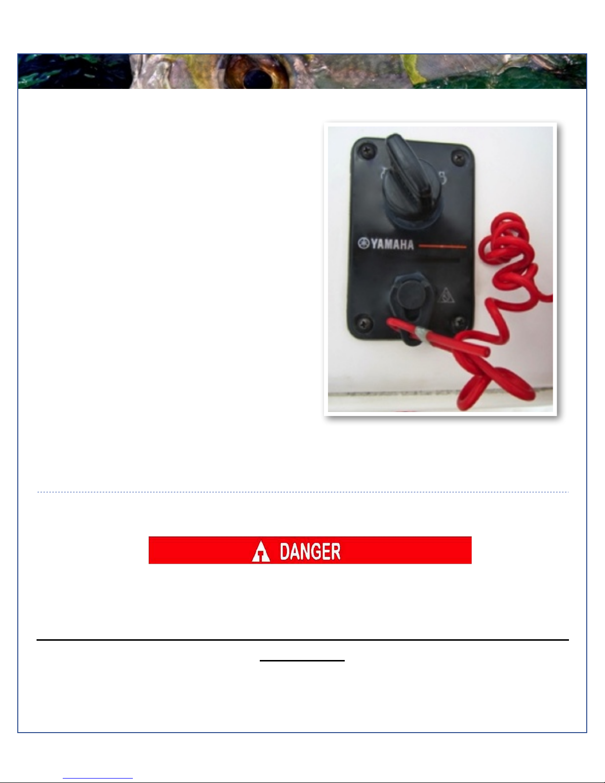
Engine Stop Switch
If activated, the spring loaded engine stop switch will
automatically shut down the engine during emergency
situations to prevent uncontrolled or unattended
operation. Certain emergency conditions (e.g., turbulent
water, wakes, unanticipated movement) may impair a
person’s ability to operate the craft safely. The switch,
located on the helm, must have the safety lanyard
attached at its base. This activates the protective
shutdown circuitry.
Securely attach the other end of the lanyard to the
operator of the boat. If the operator moves, falls or is at
an unsafe distance from the steering wheel, tension on
the lanyard will pull it from the switch. When the lanyard is
removed, the engine stop switch is released and
automatic engine shutdown occurs.
Engine stop switch (above)
Engine Stop Switch
An engine stop switch system that is not used or does not function properly can cause death or serious injury.
DO NOT operate the boat if the engine stop switch system does not function properly. Go to a Pathfinder Dealer
to have this resolved immediately
The lanyard should be securely attached to the boat operator at all times that the
engine is on.
Maverick Boat Company, Inc. • 3207 Industrial 29th St. • Fort Pierce,
Florida 34946 • (772)-465-0631 or (888)-shallow • Fax: (772) 489-2168
Model Year 2014! ! 5
FUEL-WATER SEPARATOR & DRAIN
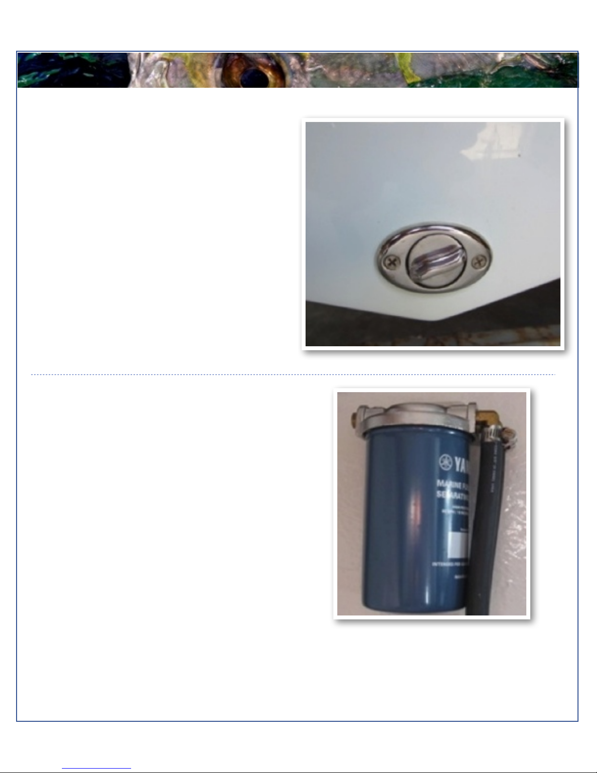
Garboard Drain Plug
The garboard drain plug is the small metal plug located at
the lowest point on the hull, at the bottom of the transom
right above the keel. The drain has been designed to so
that it can be loosened by hand while the hull is out of the
water for draining. This allows the plug to stay in contact
with the surrounding frame so you’ll never misplace or
lose it. You can completely remove the insert by pulling
back and continue turning in a counter clockwise motion.
It is manufactured with a rubber seal in place to ensure
you bilge is watertight. Always make sure before putting
the boat in the water that this plug is hand tightened
firmly. Excess water in the bilge may be an indication of a
problem with this plug or the automatic bilge pump. Refer
to page 11 of this Owner’s Manual for information on your
boats bilge system.
Fuel-Water Separator
Each Pathfinder 2600 HPS is equipped with a fuel water
separator to ensure maximum performance and protect
the outboard engine from contaminated gasoline. The fuel
separator is a metal, cylindrical unit secured to the
transom section of your central aft rigging box.
The fuel separator can be checked by removing it from
the mounting bracket in the rigging locker and dumping it
into an approved waste collection device. If there appears
to be an excessive amount of water, the filter component
should be changed. See your authorized Pathfinder
dealer for replacement parts.
Fuel/Water Separator (above)
Maintenance Note
In addition, the fuel separator should be changed as part of routine maintenance at 20, 50 and 100 hours checks
and every 100 hours thereafter.
Maverick Boat Company, Inc. • 3207 Industrial 29th St. • Fort Pierce,
Florida 34946 • (772)-465-0631 or (888)-shallow • Fax: (772) 489-2168
Model Year 2014! ! 6
SWITCH AND PANEL
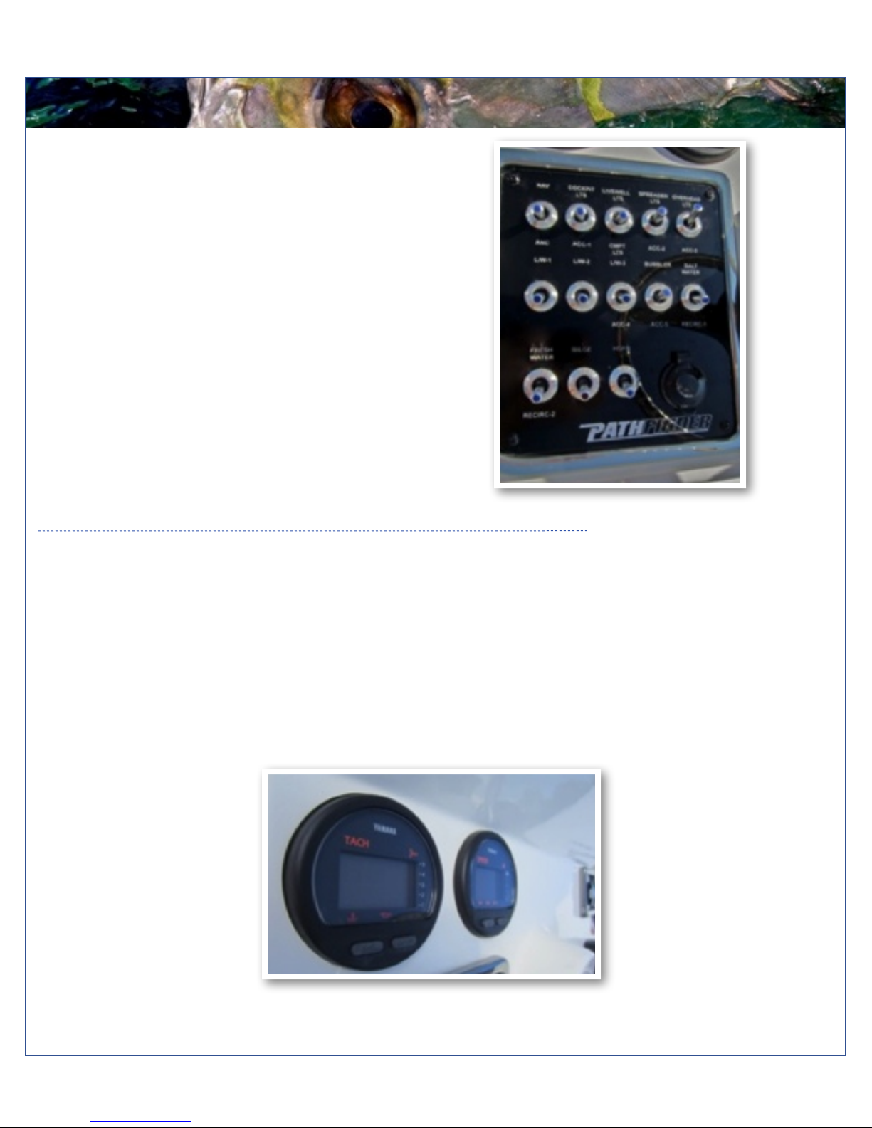
Switch Panel
The dual activation switches are set in a standard grid, these
switches can be flipped either up or down to control different
accessories. The accessories located directly above a switch are
activated when the switch is in the “Up” position and the
accessories located directly below the switch are activated when
the switch is flipped into the “Down” position. For example, in the
“Up” position the first switch in the top left corner will turn on the
navigation lights, but if in the “Down” position it will turn on the
anchor lights. The bilge switch is an on-demand switch to run your
bilge pump and is used as a backup in case the float indicator in
your bilge pump becomes clogged.
Switch Panel
Instrument Panel
The instrument panel on your Pathfinder 2600 HPS is composed of two Yamaha digital gauges and a series of
dual activation switches. The switches come with accessory plug-ins for wiring additional electronics, pumps or
electrical circuits.
The standard digital gauges include a Yamaha tachometer and a Yamaha speedometer. The tachometer has
several built in features including an engine temperature monitor, oil level monitor and engine trim indicator. The
speedometer includes a digital readout of the speed, an hour meter, trip meter and clock. For more information
on the specifics of your Yamaha gauges, see your Yamaha owner's manual.
Maverick Boat Company, Inc. • 3207 Industrial 29th St. • Fort Pierce,
Florida 34946 • (772)-465-0631 or (888)-shallow • Fax: (772) 489-2168
Model Year 2014! ! 7
BOAT LAYOUT
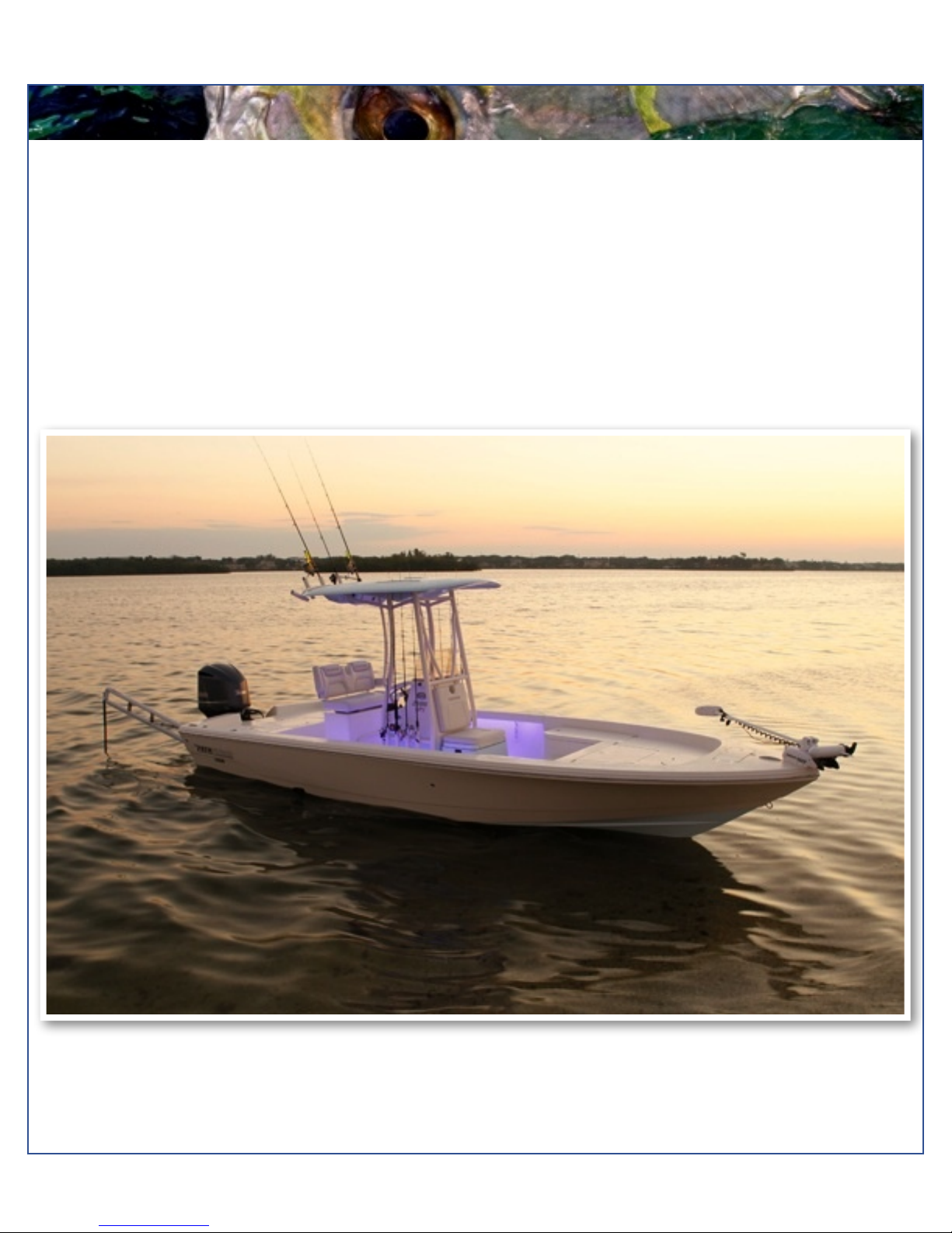
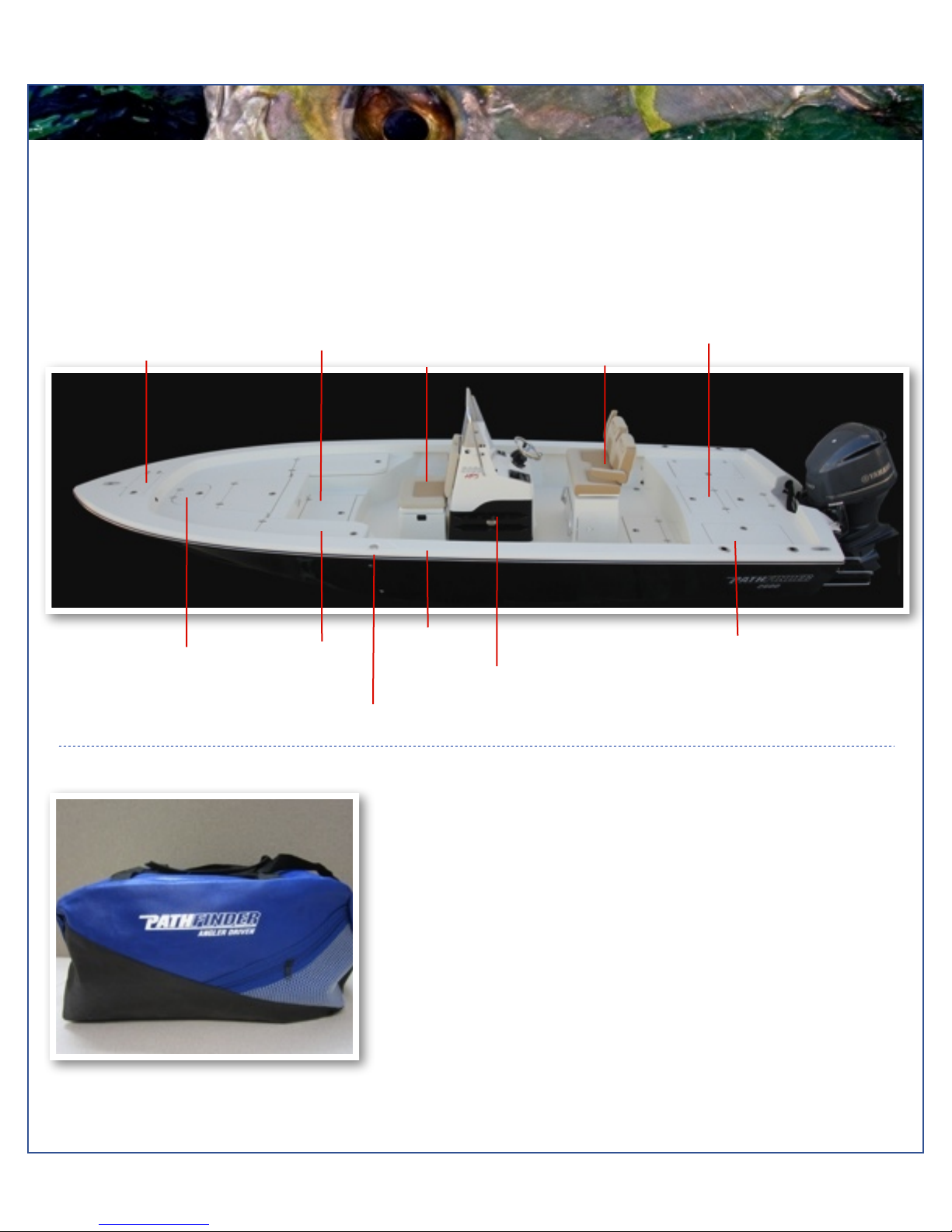
2600 HPS Boat Layout
Your Pathfinder 2600 HPS is designed to create the maximum amount of storage capacity without affecting fishing ability.
Livewells, gasketed and guttered storage compartments and lockers are built to protect your gear from the elements.
Become familiar with the boat layout and features to take advantage of their special qualities. All Pathfinder boats are
designed by anglers, for anglers, to offer the best fishing features in the Bay Boat market. The Pathfinder’s superior layout
offers hands-free fishability with the most storage and casting room available.
Anchor Locker
Fish Box
Cushioned Seat/
Cooler
Deluxe Helm Seat
Tackle Station
Livewell
Livewell
Pathfinder 2600 HPS Ditty Bag
Locking Rod
Storage (P&S)
Gunnel Rod
Holder
Console Rod Rack
Fuel Fill
Dry Storage/
Insulated Fish Box
DITTY BAG
You should have received a cloth ditty bag with your new Pathfinder 2600
HPS. Inside the ditty bag are the following items:
1 Large Livewell Standpipe
1 Small Livewell Standpipe
1 1-1/2”Livewell Pacifier Plug
2 ignition keys and Emergency Kill Cord
1 Yamaha Engine Owner’s Manual
1 Engine Start Cord
1 Garboard Drain Plug
1 Gas Fill Key
2 Glove Box Keys
1 Yamaha
Various Product Manuals
Maverick Boat Company, Inc. • 3207 Industrial 29th St. • Fort Pierce,
Florida 34946 • (772)-465-0631 or (888)-shallow • Fax: (772) 489-2168
 Loading...