

Page 1

User Manual
Page 2

Edition Notes
The Maverick MK2 Spot User Manual Rev. 3 covers the description, safety precautions,
released this edition of the Maverick MK2 Spot User Manual in September 2016.
Trademarks
CHAUVET, the Chauvet lo go and Maverick MK2 Spot are registered tr ademarks or trademarks
in the United St ates and other
countries. Other com pany and product names and lo gos referred to her ein may be tradem arks
of their respective companies.
Copyright Notice
The works of authors hip contained in this manual, includi ng, but not limited to, all design, t ext
Electronically published by Chauvet in the United States of America.
Manual Use
Chauvet authorizes it s c us tomers to download and pri nt this manual for prof ess ional inf ormation
purposes only. Chauv et expressly pr ohibits the usa ge, copy, storage, distribution , modification,
this manual or its content for any other purpose without written consent from
Chauvet.
Document
Printing
For better results, pr int this docum ent in c olor, on lett er size pap er (8.5 x 11 i n), d ouble-sided. If
Intended
Any person in charge of ins talling, operatin g, and/or m aintaining this product s hould com pletely
read through the guide tha t shipped with the product, as well as this manual, before install ing,
operating, or maintaining this product.
Disclaimer
Chauvet believes that the information contained in this manual is accurate in all respects.
loss, damage or disruption caused by any errors or omissions in this
document, whether such errors or omissions result from negligence, accident or any other
and does not commit to make, any such revisions.
Document
The Maverick MK2 Spot User Manual Rev. 4 su persedes all previous vers ions of this manual.
Discard any older versions of this manual and replace with this version. Go to
www.chauvetprofessional.com for the latest version.
Edition Notes
Audience
installation, programming, operation, and maintenance of the Maverick MK2 Spot. Chauvet
of Chauvet & Sons, LLC. ( d/b/a Chauvet and C hauvet Lighting)
and images are owned by Chauvet.
© Copyright 2016 Chauvet & Sons, LLC. All rights reserved.
or printing of
using A4 paper (210 x 297 mm), configure your printer to scale the content accordingly.
However, Chauvet assum es no responsibility and specifically discla ims any and all liability to
any party for any
cause. Chauvet res erves the ri ght to re vise the c ontent of this docum ent without an y obligatio n
to notify any per son or c ompany of such re visi on, however, Chauvet has no obligation t o make,
Revision
Maverick MKII Spot User Manual Rev. 4
Page 3

Table of Contents
Table of Contents
1. Before You Begin ................................................................................................................................................... 1
What Is Included ....................................................................................................................................................................1
Claims .................................................................................................................................................................................................... 1
Manual Conventions .............................................................................................................................................................................. 1
Symbols ................................................................................................................................................................................................. 1
Product At A Glance ..............................................................................................................................................................1
Safety Notes ..........................................................................................................................................................................2
Personal Safety...................................................................................................................................................................................... 2
Mounting And Riggi ng ............................................................................................................................................................................ 2
Power And Wiring .................................................................................................................................................................................. 2
Operation ............................................................................................................................................................................................... 2
Expected LED Lifespan .........................................................................................................................................................2
2. Introduction ............................................................................................................................................................ 3
Description .............................................................................................................................................................................3
Features at a glance ..............................................................................................................................................................3
Overview ................................................................................................................................................................................3
Dimensions ............................................................................................................................................................................4
3. Setup ....................................................................................................................................................................... 5
AC Power ...............................................................................................................................................................................5
AC Plug.................................................................................................................................................................................................. 5
Fuse Replacement ................................................................................................................................................................................. 5
Mounting ................................................................................................................................................................................6
Orientation ............................................................................................................................................................................................. 6
Signal Connections ................................................................................................................................................................7
Art-Net™ Connection ............................................................................................................................................................................. 7
sACN Connection .................................................................................................................................................................................. 7
4. Operation ................................................................................................................................................................ 8
Touchscreen and Control Panel Description .........................................................................................................................8
Menu Map ..............................................................................................................................................................................8
Operating Settings Configuration .........................................................................................................................................12
Home Screen ....................................................................................................................................................................................... 12
Network Setup ..................................................................................................................................................................................... 12
Personality ........................................................................................................................................................................................... 14
Settings ................................................................................................................................................................................................ 14
Test Mode ............................................................................................................................................................................................ 18
System Informat ion .............................................................................................................................................................................. 18
Offset Mode .........................................................................................................................................................................19
DMX Values .........................................................................................................................................................................21
32CH ....................................................................................................................................................................................21
24CH ....................................................................................................................................................................................23
Gobo Designs ......................................................................................................................................................................26
Color Wheel .........................................................................................................................................................................26
Gobo Replacement .............................................................................................................................................................................. 27
5. Firmware Update .................................................................................................................................................. 28
6. Technical Information .......................................................................................................................................... 31
Product Maintenance ...........................................................................................................................................................31
Error Indication .....................................................................................................................................................................31
7. Technical Specificat i ons ..................................................................................................................................... 32
Returns ...................................................................................................................................................................... 33
Contact Us ................................................................................................................................................................ 34
Maverick MKII Spot User Manual Rev. 4 -i-
Page 4
1. BEFORE YOU BEGIN
What Is
• Maverick MK2 Spot
• User Manual
Claims
Carefully unpack the pr oduct immediately and check the box to make sure all the parts are in
ts (the product and included accessories) appear damaged from
. Failure to
report damage to the c arrier immediately may inval idate your claim. In addition, keep the box
For other issues, such as missing components or parts, damage not related to shipping, or
concealed damage, file a claim with Chauvet within 7 days of delivery.
Manual
Convention
Meaning
1–512
A range of values in the text
50/60
A set of mutually exclusive values in the text
<SET>
A button on the product’s control panel
Settings
A product function or a menu option
MENU>Settings
A sequence of menu options
ON
A unique value to be entered or selected in a menu
Symbols
Symbols
Meaning
Critical installation, configuration, or operation information. Failure to
damage third-party equipment, or cause harm to the operator.
The term “DMX” used throughout this manual refers to the USITT DMX512-A digital data
transmission protocol.
Product At A
x
x
x
P
x
P
P
x
Before You Begin
Included
Conventions
• True 1 compatible power cord
• 2 Omega brackets
• Warranty card
the package and are in good condition.
If the box or the conten
shipping or show signs of mishandling, notify the carr ier immediately, not Chauvet
and contents for inspection.
Use on Dimmer
Glance
Maverick MK2 Spot User Manual Rev. 4 -1-
Outdoor Use
Master/Slave
DMX
comply with this information may cause the product not to work,
Important installation or configuration information. Failure to comply
with this information may keep the product from working.
Useful information.
Auto Programs
Auto-Ranging Power Supply
Replaceable Fuse
User-Serviceable
Page 5

Safety Notes
Read all the following Safety Notes befor e wor k ing with this product. These notes include
important information about the installation, usage, and maintenance of this product.
This product contains no user-serviceable parts. Any reference t o servicin g in this User
housing or attempt any repairs.
Personal Safety
• Avoid direct eye exposure to the light source while the product is on.
• Do not touch this product’s housing during operation because it may be very hot.
Mounting And
• This product is for indoor use only! To prevent risk of fire or shock, do not expose this
• Never carry the product by the power cord or any moving part.
Power And
• Make sure the power cord is not crimped or damaged.
• Never disconnect this product by pulling or tugging on the power cable.
Operation
• Do not operate this product if you see damage on the housing, lenses, or cables. Have the
• In case of a serious operating problem, stop using this product immediately!
Expected LED
LEDs gradually decline i n brightness over time, m ostly because of heat. Packaged in c lusters,
LED conditions. For this
projection intensity may also help to extend the LEDs’ lifespan.
Before You Begin
Manual will only apply to properly trained Chauvet certified technicians. Do not open the
All applicable local codes and regulations apply to proper installation of this product.
• Always disconnect this product from its power source before servicing.
• Always connect this product to a grounded circuit to avoid the risk of electrocution.
Rigging
Wiring
product to rain or moisture. (IP20)
• CAUTION: When transferring product from extreme temperature environments, (e.g. cold
truck to warm humid ballroom) condensation may form on the internal electronics of the
product. To avoid causing a failure, allow product to fully acclimate to the surrounding
environment before connecting it to power.
• Mount this product in a location with adequate ventilation, at least 20 in (50 cm) from
adjacent surfaces.
• Make sure there are no flammable materials close to this product while it is operating.
• When hanging this product, always secure to a fastening device using a safety cable.
• Always make sure you are connecting this product to the proper voltage in accordance
with the specifications in this manual or on the product’s specification label.
• To eliminate unnecessary wear and improve its lifespan, during periods of non-use
completely disconnect the product from power via breaker or by unplugging it.
• Never connect this product to a dimmer pack or rheostat.
• Make sure to replace the fuse with another of the same type and rating.
damaged parts replaced by an authorized technician at once.
• Do not cover the ventilation slots when operating to avoid internal overheating.
• The maximum ambient temperature is 113 °F (45 °C). Do not operate this product at a
higher temperature.
If your Chauvet product requires service, contact Chauvet Technical Support.
Lifespan
-2- Maverick MK2 Spot User Manual Rev. 4
LEDs exhibit higher operating temperatures than in ideal, singlereason, using clustered LE Ds at their fullest intensity signif icantly reduces the LEDs’ lif espan.
Under normal conditions , this lifes pan can b e 40,000 t o 50,000 ho urs. If ext ending this lifes pan
is vital, lower the opera ting temperature by improving the venti lation around the product and
reducing the ambient temperature to an optimal operating range. In addition, limiting the overall
Page 6
2. INTRODUCTION
Description
Stunningly bright with prec ision engineered optics and a color m ixing system that will leave you
breathless, the Ma veric k MK2 Spot sets new standards in moving he ad LED s pot s . Po wered by an
industry leading 440W LED engine, this fixture boasts a CMY+CTO color mixing system, two 6
lot and lock gobo wheels, a 7 positi on + white color wheel, variable frost and 3
facet prism. All of this proj ected through a 13° to 37° zoom system. With the ability to contro l the
ery situation. As an
added feature, this fixture can receive Art-Net in, and send out DMX, simplifying cable runs.
Features at a
• 440W LED light engine
• True 1 compatible power input
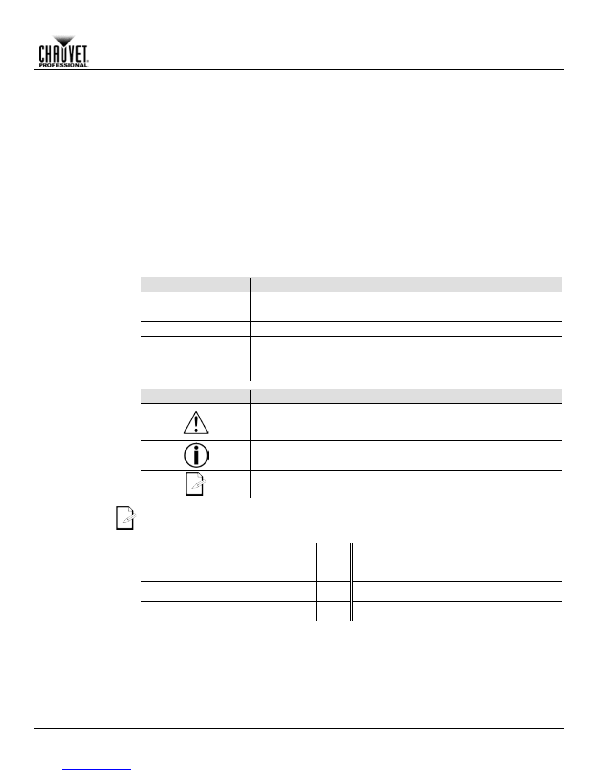
Rear View
Display
Menu
Buttons
Power
Switch
Yoke
Handles
Rubber Foot
(x4)
Fans
etherCON® Through
Ports
3-pin DMX
In/Out
5-pin DMX
In/Out
True 1
Compatible
Power In
Fuse-Holder
Indicator
Front View
position rotating s
Maverick MK2 Spot over D MX, Art-Net, or b y WDMX, there is an option f or ev
Introduction
glance
• 16-bit Dimming
• Variable CMY+CTO color mixing
• Two rotating, indexing and interchangeable slot and lock gobos
• DMX , WDMX, sACN, and Art-Net control
• 13° to 37° Zoom angle
• Iris, 3-facet prism, and frost for beam control
Overview
Maverick MK2 Spot User Manual Rev. 4 -3-
Ethernet LED
Wireless
Antenna
Page 7
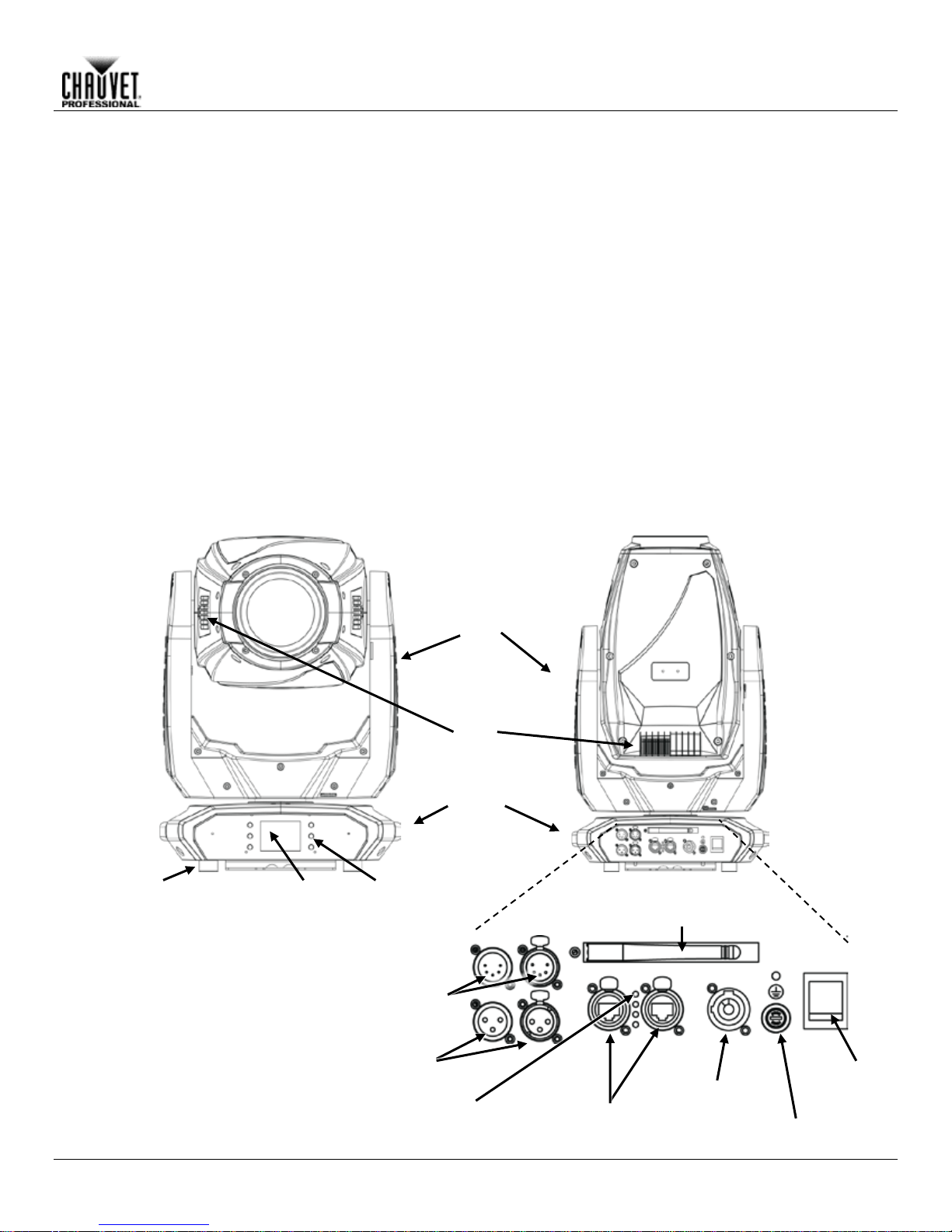
14.6 in
371 mm
15.6 in
396 mm
21.6 in
549 mm
9.8 in
249 mm
17.6 in
447 mm
4.5 in
114 mm
15.1 in
384 mm
9.8 in
249 mm
11.1 in
282 mm
26.4 in
671 mm
Introduction
Dimensions
-4- Maverick MK2 Spot User Manual Rev. 4
Page 8

3. SETUP
AC Powe r
Each Ma verick MK2 Spot has an auto-ranging power supply that w orks with an input voltage
Maverick
Technical
e
:
www.chauvetprofessional.com.
• Always connect this product to a protected circuit with an appropriate electrical
completely disconnect the product from power via breaker or by unplugging it.
AC Plug
The Mav erick MK2 Spot c omes with a power input cord ter minated with a True 1 com patible
end (U.S. market) . If the power input
cord that came with your product has no plug, or if you need to change the Ediso n plug, use the
table below to wire the new plug.
Connection
Wire (U.S.)
Wire (Europe)
Screw Color
AC Live
Black
Brown
Yellow or Brass
AC Neutral
White
Blue
Silver
AC Ground
Green/Yellow
Green/Yellow
Green
Fuse
Disconnect this product from the power outlet.
Screw the fuse holder cap back in place and reconnect power.
Make sure to disconnect the product’s power cord before replacing a blown fuse. Always
replace the blown fuse with another of the same type and rating.
Setup
range of 100 to 240 VAC, 50/60 Hz. T o determine the power requirements for each
MK2 Spot, refer to the label affixed to the product. You can also refer to the
Specifications chart in this manual.
The listed current r ati ng in d icat es t he maximum current dra w duri ng nor mal operation. For mor
information, you may download Sizing Circuit Breakers from the Chauvet website
ground to avoid the risk of electrocution or fire.
• Never connect this product to a rheostat (variable resistor) or dimmer circuit, even if
the rheostat or dimmer channel serves only as a 0 to 100% switch.
• To eliminate unnecessary wear and improve its lifespan, during periods of non-use
connector on one end and an Edison p lug on the other
1.
Replacement
Using a flat-head screwdriver, unscrew the fuse holder cap from the housing. 2.
Remove the blown fuse and replace with another fuse of the same type and rating 3.
(F 10 A, 250 V).
4.
Maverick MK2 Spot User Manual Rev. 4 -5-
Page 9
Mounting
Before mounting this product, read and follow the Safety Notes. For our CHAUVET
Professional line of mounting clamps, go to http://trusst.com/products/.
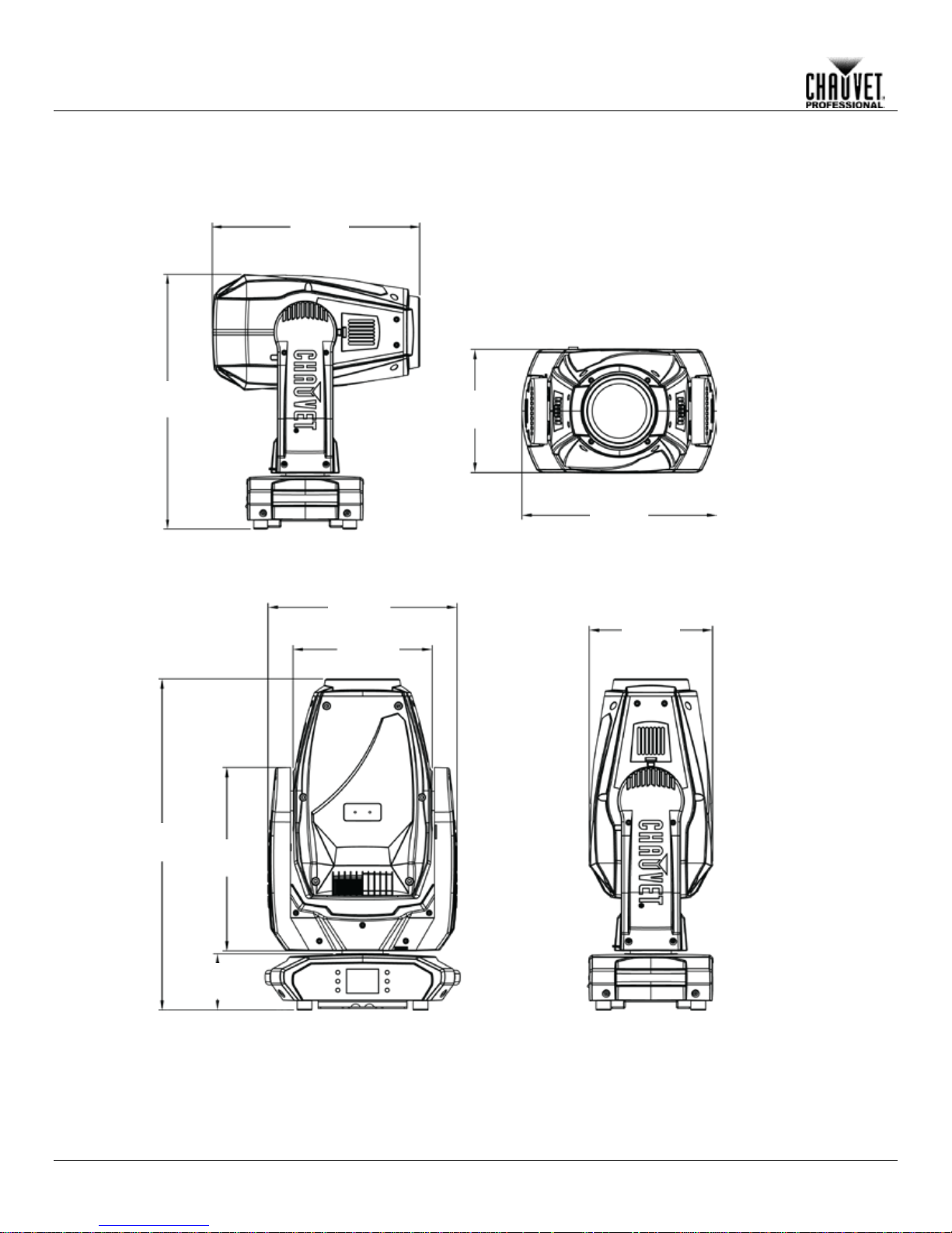
Orientation
Always mount this product in a safe position and make sure there is adequate room for
can be suspended upright
or upside down using th e 2 Omega brackets included, or it can b e pl ac ed o n its ru bber f eet on a
flat level surface.
Chauvet recommends using the following general guidelines when mounting this product:
• When selecting an installation location, consider easy access to this product for operation,
• Leave enough slack on the cable to prevent tension and pull on the plugs.
Mounting Diagram
Safety
Cable
Overhead Mounting
Floor Mounting
Rubber Feet (x4)
Mounting Clamps
Omega Brackets
Setup
ventilation, configurat ion, and maintenanc e. The Maverick MK2 Spot
programming adjustments, and routine maintenance.
• Make sure to mount this product away from any flammable material as indicated in the
Safety Notes.
• Never mount in places where rain, high humidity, extreme temperature changes, or
restricted ventilation may affect the product.
• If hanging this product, make sure that the mounting location can support the product’s
weight. See the T echnic al Specif icat io ns for the weight-bearing requirements of this
product.
• When hanging this product, always secure to a fastening device using a safety cable. For
our CHAUVET Professional line of safety cables, go to http://trusst.com/products/.
• When mounting the product on the floor, make sure that the product and cables are away
from people and vehicles.
• Place the Maverick MK2 Spot so that it can move freely without hitting anything or anybody.
-6- Maverick MK2 Spot User Manual Rev. 4
Page 10
Setup
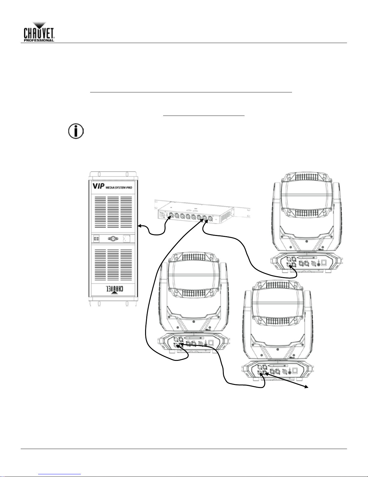
Signal Connections
The Maverick MK2 Spot can receive DMX, sACN or Art-Net™ signals. The Maverick MK2 Spot
http://www.chauvetlighting.com/downloads/DMX_Primer_Rev9_ML_WO.pdf
Art-Net™
Art-Net™ is an Et hernet pr otocol th at uses TCP/IP, which transfers large am ount s of DMX512
Net™ protocol
Art-Net™ designed by and copyright Artistic Licence Holdings Ltd.
sACN
Also known as ANSI E1.31 , stream ing ACN is an Ethernet pr otocol that uses the la yering and
Association (PLASA).
has 2 etherCON® thr oug h port s, an d 3- and 5-pin DM X In an d O ut por ts . For more information
about DMX, read the DMX primer at:
Connection
data using an etherCON® RJ45 connection over a large network. An Artdocument is available from www.chauvetprofessional.com.
Chauvet Professional recommends using unicast Art-Net™ for best results.
Connection
formatting of Architectur e for Control Networ ks to transport DMX512 data over TCP/I P or any
other ACN compatible network. ACN is maintained by the Professional Lighting and Sound
Switch or Router
(such as the NET-Switch
from CHAUVET Professional)
Connection
Diagram
Computer/Controller
(running TCP/IP
protocol)
To other TCP/IP
Devices
Maverick MK2 Spot User Manual Rev. 4 -7-
Page 11
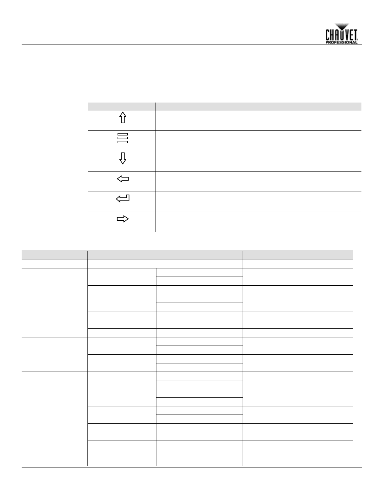
The Maverick MK2 Spot has a touchscreen display as well as 6 control buttons. Navigate the menu structure by
the menu (see Touchscreen Calibration a n d Touchscreen Lock).
Touchscreen
Control
Panel
Description
Button
Function
(<UP>)
(<MENU>)
(<DOWN>)
(<LEFT>)
(<ENTER>)
Enables the currently displayed menu or sets the currently selected value
(<RIGHT>)
Menu Map
Main Level
Programming Levels
Description
Address
000–512
Network Setting
YES
NO
Manual
DHCP
Static
Universe
0 ~ 255
Set the Universe
ArtNetIp
002.243.075.222
IP setting
SubMask
255.000.000.000
Subnet Mask
YES
NO
YES
NO
DMX
WDMX
ArtNet
sACN
YES
NO
YES
NO
NO
YES
AUTO
< >
< >
< >
< >
< >
< >
Operation
4. OPERATION
pressing the buttons, touching the images of the buttons on the sides of the display, or touch ing the desired
menu option on the display directly. The touchscreen can be locked and calibrated through the Setup options in
and
Network Setup
Ethernet to DMX
IP Mode
Navigates upwards through the menu list or increases the numeric value
when in a function
Exits from the current menu or function
Navigates downwards through the menu list or decreases the numeric
value when in a function
Navigates leftwards through the menu list
into the selected function
Navigates rightwards through the menu list
Turn on Art-Net to DMX capability
Selection of IP mode
(Static IP: 2.243.76.222)
DMX 24CH
Personality
DMX 32CH
Choose 24 Channels of DMX
Choose 32 Channels of DMX
Control Mode
Signal Selection
Settings
-8- Maverick MK2 Spot User Manual Rev. 4
Pan Reverse
Tilt Reverse
Screen Reverse
Reverse the Pan
Reverse the Tilt
Manually or automatically reverse the
screen
Page 12

Operation
Main Level
Programming Levels
Description
540
360
180
270
180
90
YES
NO
YES
NO
YES
NO
YES
NO
YES
NO
YES
NO
YES
NO
Fast
Slow
YES
NO
30S
1M
5M
ON
Hold
Close
Auto
Full
ECO
Linear
Square
I Square
Scurve
Smooth
Fast
Pan/Tilt
Iris/ Prism
Color/CMY + CTO
Gobo/Gobo Rotate
Zoom/Frost/
Focus
All
Pan Angle
Tilt Angle
BL. O. P/T Move
BL. O. Color Move
BL. O. Gobo Move
Calibration
Touchscreen Lock
Lock Screen
Swap X/Y
X/Y Mode
Change the Pan angle
Change the Tilt angle
Enable/disable XY blackout
Enable/disable color blackout
Enable/disable gobo blackout
Turn on Calibration
Lock the touchscreen
Lock the buttons and touchscreen
PASSCODE: 0920
Swap the pan and tilt
Pan and tilt speed
Settings
(Continued)
WDMX Reset
Backlight Timer
Loss of Data
Fans
Dimmer Curve
Dimmer Speed
Reset Function
YES/NO
Reset the wireless DMX
Set the backlight to turn off automatically
after a chosen time
Loss of data setting
Change the fan speed mode
Set the dimmer curve
Change the dimmer speed
Reset individual functions to factory
Maverick MK2 Spot User Manual Rev. 4 -9-
Page 13

Main Level
Programming Levels
Description
YES
NO
Auto Test
Auto test the product
Pan
0 ~ 255
Pan Fine
0 ~ 255
Tilt
0 ~ 255
Tilt Fine
0 ~ 255
P/T Speed
0 ~ 255
Dimmer
0 ~ 255
Dimmer Fine
0 ~ 255
Shutter
0 ~ 255
Virtual
Shaking
Cyan
0 ~ 255
Megenta
0 ~ 255
Yellow
0 ~ 255
CTO
0 ~ 255
Color
0 ~ 255
Gobo 1
0 ~ 255
Gobo 1 Index
Fine
Gobo 1 Rotate
0 ~ 255
Gobo 2
0 ~ 255
Gobo 2 Index
Fine
Gobo 2 Rotate
0 ~ 255
Focus
0 ~ 255
Focus Fine
0 ~ 255
Focus Auto
0 ~ 255
Zoom
0 ~ 255
Zoom Fine
0 ~ 255
Prism
0 ~ 255
Prism Rotate
0 ~ 255
Iris
0 ~ 255
Frost
0 ~ 255
CMY Macro
0 ~ 255
CMY Macro
Speed
Special
Function
Operation
Test
Factory Settings
Manual Test
Reset all functions to factory
0 ~ 255
0 ~ 255
Individually test each function/channel
0 ~ 255
0 ~ 255
0 ~ 255
-10- Maverick MK2 Spot User Manual Rev. 4
Page 14

Main Le vel
Programming Levels
Description
Fixture Information
Ver V1
Current Version
Running Mode DMX
DMX Address 001
Temperature 025
Current Temparature
Fixture Hours 00000
Current active hours
ArtNetIp 002.243.075.222
Current IP address
SubMask 255.000.000.000
Current subnet mask
MAC 00.04.a3.08.00.00
MAC address
Base Fan1 Speed 2000rpm
View speed setting
Base Fan2 Speed 2000rpm
View speed setting
Head Fan1 Speed 2000rpm
View speed setting
Head Fan2 Speed 2000rpm
View speed setting
Error Information
_ _ _ _ _
Will appear on screen
Frequency
0Hz
Pan
0 ~ 255
Pan Fine
0 ~ 255
Tilt
0 ~ 255
Tilt Fine
0 ~ 255
P/T Speed
0 ~ 255
Dimmer
0 ~ 255
Dimmer Fine
0 ~ 255
Shutter
0 ~ 255
Virtual Shaking
0 ~ 255
Cyan
0 ~ 255
Megenta
0 ~ 255
Yellow
0 ~ 255
CTO
0 ~ 255
Color
0 ~ 255
Gobo 1
0 ~ 255
Gobo 1 Index Fine
0 ~ 255
Gobo 1 Rotate
0 ~ 255
Gobo 2
0 ~ 255
Gobo 2 Index Fine
0 ~ 255
Gobo 2 Rotate
0 ~ 255
Focus
0 ~ 255
Focus Fine
0 ~ 255
Focus Auto
0 ~ 255
Zoom
0 ~ 255
Zoom Fine
0 ~ 255
Prism
0 ~ 255
Prism Rotate
0 ~ 255
Iris
0 ~ 255
Frost
0 ~ 255
CMY Macro
0 ~ 255
CMY Macro Speed
0 ~ 255
Special Function
0 ~ 255
Fan Information
Operation
Current Mode
Information
Channel Information
Status of individual channel
Maverick MK2 Spot User Manual Rev. 4 -11-
Page 15

Operating Settings Configuration
Home Screen
The Ma verick MK2 S pot has a hom e screen that sho ws the pr otocol mode, the IP ad dress or D MX
To see the hom e screen, pr ess
<MENU> repeat edly until it appears on the display.
Start Address
To set the starting address, set the Control Mode and then follow the instructions below:
Press <ENTER>.
Network Setup
Ethernet To DMX
The Maverick MK2 Spot can convert a single ethernet input signal to a single DMX output signal.
Press <ENTER>.
IP Mode
The IP address of the Maver ick MK2 Spot can be set m anuall y, by the net work , or to a pre -set sta tic
Press <ENTER>.
Operation
address, the DMX per sonal ity, an d the c urrent pr oduct tem peratur e.
Press <MENU> repeatedly until the Home Screen shows on the display. Press <ENTER>. 1.
Use <UP>, <DOWN>, <LEFT>, or <RIGHT> to select Start Address, or touch the display 2.
where it says Start Address.
If using the buttons instead of the touchscreen, press <ENTER>. 3.
Enter the starting address (001–512) with one of the following methods: 4.
• Type the address number using the number pad that shows on the touchscreen display.
or
• Using the buttons (or the button icons on the sides of the display),
Use <LEFT> or <RIGHT> to select the digit to be altered. a.
Use <UP> or <DOWN> to increase or decrease the number value of that digit. b.
Repeat until the address is set as desired. c.
5.
The universe of the TCP/IP protocol will be th e universe of the DMX function.
To activate or deactivate the Ethernet to DMX function, do the following:
1.
Press <MENU> repeatedly until the Home Screen shows on the display. Press <ENTER>.
Use <UP>, <DOWN>, <LEFT>, or <RIGHT> to select Network Setup, or touch the display 2.
where it says Network Setup.
If using the buttons instead of the touchscreen, press <ENTER>. 3.
Use <UP> or <DOWN> to select Ethernet to DMX, or touch the display where it says Ethernet 4.
to DMX.
If using the buttons instead of the touchscreen, press <ENTER>. 5.
Use <UP>, <DOWN>, <LEFT>, or <RIGHT> to select NO (deactivate) or YES (activate), or 6.
touch the display where it says the desired setting.
7.
address specific to each product. To set the IP Mode, follow the instructions below:
1.
Press <MENU> repeatedly until the Home Screen shows on the display. Press <ENTER>.
Use <UP>, <DOWN>, <LEFT>, or <RIGHT> to select Network Setup, or touch the display 2.
where it says Network Setup.
If using the buttons instead of the touchscreen, press <ENTER>. 3.
Use <UP> or <DOWN> to select IP Mode, or touch the display where it says IP Mode. 4.
If using the buttons instead of the touchscreen, press <ENTER>. 5.
Use <UP>, <DOWN>, <LEFT>, or <RIGHT> to select from: 6.
• Manual (set the IP address with the control panel),
• DHCP (the network sets the IP address),
or
• Static (a pre-set address specific to each product),
or touch the display where it says the desired mode.
7.
-12- Maverick MK2 Spot User Manual Rev. 4
Page 16

Operation
Subnet and
Universe
The Subnet and universe must be assigned through the product menu. To set the Subnet and
Press <ENTER>.
ArtNet IP Address
To set the IP address, do the following:
Press <ENTER>.
Subnet Mask
To set the Subnet Mask, do the following:
Press <ENTER>.
Universe do the following:
1.
Press <MENU> repeatedly until the Home Screen shows on the display. Press <ENTER>.
Use <UP>, <DOWN>, <LEFT>, or <RIGHT> to select Network Setup, or touch the display 2.
where it says Network Setup.
If using the buttons instead of the touchscreen, press <ENTER>. 3.
Use <UP> or <DOWN> to select Subnet and Universe, or touch the display where it says 4.
Subnet and Universe.
If using the buttons instead of the touchscreen, press <ENTER>. 5.
Enter the universe address (0–254 for ArtNet, 0–255 for sACN) with one of the following 6.
methods:
• Type the universe number using the number pad that shows on the touchscreen display.
or
• Using the buttons (or the button icons on the sides of the display),
Use <LEFT> or <RIGHT> to select the digit to be altered. a.
Use <UP> or <DOWN> to increase or decrease the number value of that digit. b.
Repeat until the universe or subnet is set as desired. c.
7.
Press <MENU> repeatedly until the Home Screen shows on the display. Press <ENTER>. 1.
Use <UP>, <DOWN>, <LEFT>, or <RIGHT> to select Network Setup, or touch the display 2.
where it says Network Setup.
If using the buttons instead of the touchscreen, press <ENTER>. 3.
Use <UP> or <DOWN> to select ArtNetIP, or touch the display where it says ArtNetIP. 4.
If using the buttons instead of the touchscreen, press <ENTER>. 5.
Set the IP address (from 000.000.000.000 to 255.255.255.255) with one of the following 6.
methods:
• Through the touchscreen:
Touch the display where it shows the byte (set of three numbers) to be changed. a.
Use the number pad on the display to enter the desired number. b.
Repeat until the IP address is set as desired. c.
• With the buttons:
Use <LEFT> or <RIGHT> to select the byte (set of three numbers) to be changed). a.
Use <UP> or <DOWN> to increase or decrease the value. b.
Repeat until the IP address is set as desired. c.
7.
Press <MENU> repeatedly until the Home Screen shows on the display. Press <ENTER>. 1.
Use <UP>, <DOWN>, <LEFT>, or <RIGHT> to select Network Setup, or touch the display 2.
where it says Network Setup.
If using the buttons instead of the touchscreen, press <ENTER>. 3.
Use <UP> or <DOWN> to select SubMask, or touch the display where it says SubMask. 4.
If using the buttons instead of the touchscreen, press <ENTER>. 5.
Set the Subnet Mask (from 000.000.000.000 to 255.255.255.255) with one of the following 6.
methods.
• Through the touchscreen:
Touch the display where it shows the byte (set of three numbers) to be changed. a.
Use the number pad on the display to enter the desired number. b.
Repeat until the Subnet Mask is set as desired. c.
• With the buttons:
Use <LEFT> or <RIGHT> to select the byte (set of three numbers) to be changed). a.
Use <UP> or <DOWN> to increase or decrease the value. b.
Repeat until the Subnet Mask is set as desired. c.
7.
In DHCP or Static IP Mode, the IP and SubMask menu settings have no effect on the product.
Maverick MK2 Spot User Manual Rev. 4 -13-
Page 17

Personality
To set which DMX personality to use, do the following:
(confirm) or touch the
Press <ENTER>.
Settings
To reach the Settings menu, follow the instructions below:
If using the buttons instead of the touchscreen, press <ENTER>.
Control Mode
The Maverick MK2 Sp ot can be set to resp ond to DMX, WDMX , Art-Net™ or sACN. The pr otocol
Press <ENTER>.
controller and the product. See WDMX Reset for troubleshooting information.
Pan/Tilt
Orientation
To set whether the pan or tilt orientation is normal or inverted:”
Press <ENTER>.
Display
Orientation
To set which way the display faces, do the following:
Press <ENTER>.
Operation
Press <MENU> repeatedly until the Home Screen shows on the display. Press <ENTER>. 1.
Use <UP>, <DOWN>, <LEFT>, or <RIGHT> to select Personality, or touch the display where it 2.
says Personality.
If using the buttons instead of the touchscreen, press <ENTER>. 3.
Use <UP>, <DOWN>, <LEFT>, or <RIGHT> to select DMX 24CH or DMX 32CH, or touch the 4.
display where it says the desired option.
If using the buttons instead of the touchscreen, press <ENTER>. 5.
6.
Use <UP>, <DOWN>, <LEFT>, or <RIGHT> to select NO (cancel) or YES
display where it says the desired option.
7.
Press <MENU> repeatedly until the Home Screen shows on the display. Press <ENTER>. 1.
Use <UP>, <DOWN>, <LEFT>, or <RIGHT> to select Settings, or touch the displa y where it 2.
says Settings.
3.
configuration must be set for the product to respond correctly to the controller(s). See the Menu
Map for more information.
To configure the protocol for the Maverick MK2 Spot, follow the instructions below:
1.
Navigate to the Settings menu.
Use <UP> or <DOWN> to select Control Mode, or touch the display where it says Control 2.
Mode.
If using the buttons instead of the touchscreen, press <ENTER>. 3.
Use <UP>, <DOWN>, <LEFT>, or <RIGHT> to select DMX, WDMX, sACN, ArtNet., or touch 4.
the display where it says the desired option.
5.
For WDMX control, ensure the antenna is raised and there are no obstructions between the
Navigate to the Settings menu. 1.
Use <UP> or <DOWN> to select Pan Reverse or Tilt Reverse, or touch the display where it 2.
says the desired setting.
If using the buttons instead of the touchscreen, press <ENTER>. 3.
Use <UP>, <DOWN>, <LEFT>, or <RIGHT> to select NO (normal orientation) or YES (inverted 4.
orientation), or touch the display where it says the desired option.
5.
Navigate to the Settings menu. 1.
Use <UP> or <DOWN> to select Screen Reverse, or touch the display where it says Screen 2.
Reverse.
If using the buttons instead of the touchscreen, press <ENTER>. 3.
Use <UP>, <DOWN>, <LEFT>, or <RIGHT> to select NO (display is normal), YES (display is 4.
inverted), or AUTO (the display automatically detects which way the product is facing and
orients itself accordingly), or touch the display where it says the desired option.
5.
-14- Maverick MK2 Spot User Manual Rev. 4
Page 18

Operation
Pan/Tilt Angle
Range
To set the range of motion the pan or tilt is permitted:
, or touch the display where it says the
Press <ENTER>.
Blackout on
Pan/Tilt
Movement
To set whether the product will black out during pan or tilt movement, follow the instructions below:
BL. O. P/T
Press <ENTER>.
Blackout on Color
Movement
To set whether the product will black out during color movement, follow the instructions below:
Press <ENTER>.
Blackout on Gobo
Movement
To set whether the product will black out during gobo movement, follow the instructions below:
Press <ENTER>.
Touchscreen
Calibration
If the touchscreen is not responding correctly, it may need to be calibrated. To do so:
Follow the instructions, touching the points as they appear on the display.
Touchscreen Lock
To lock or unlock the touchscreen control panel, do the following:
Press <ENTER>.
Navigate to the Settings menu. 1.
2.
Use <UP> or <DOWN> to select Pan Angle or Tilt Angle
desired setting.
If using the buttons instead of the touchscreen, press <ENTER>. 3.
Use <UP>, <DOWN>, <LEFT>, or <RIGHT> to select 540 (540°), 360 or 270 (360° or 270° for 4.
pan or tilt respectively), 180 (180°), or 90 (90°) or touch the display where it says the desired
option.
5.
Navigate to the Settings menu. 1.
2.
Use <UP> or <DOWN> to select BL. O. P/T Move, or touch the display where it says
Move.
If using the buttons instead of the touchscreen, press <ENTER>. 3.
Use <UP>, <DOWN>, <LEFT>, or <RIGHT> to select NO (do not black out) or YES (black out 4.
during movement), or touch the display where it says the desired option.
5.
Navigate to the Settings menu. 1.
Use <UP> or <DOWN> to select BL. O. Color Move, or touch the display where it says BL. O. 2.
Color Move.
If using the buttons instead of the touchscreen, press <ENTER>. 3.
Use <UP>, <DOWN>, <LEFT>, or <RIGHT> to select NO (do not black out) or YES (black out 4.
during movement), or touch the display where it says the desired option.
5.
Navigate to the Settings menu. 1.
Use <UP> or <DOWN> to select BL. O. Gobo Move, or touch the display where it says BL. O. 2.
Gobo Move.
If using the buttons instead of the touchscreen, press <ENTER>. 3.
Use <UP>, <DOWN>, <LEFT>, or <RIGHT> to select NO (do not black out) or YES (black out 4.
during movement), or touch the display where it says the desired option.
5.
Navigate to the Settings menu. 1.
Use <UP> or <DOWN> to select Calibration, or touch the display where it says Calibration. 2.
If using the buttons instead of the touchscreen, press <ENTER>. 3.
Use <UP>, <DOWN>, <LEFT>, or <RIGHT> to select NO (do not calibrate) or YES (calibrate), 4.
or touch the display where it says the desired option.
Press <ENTER>. 5.
6.
Navigate to the Settings menu. 1.
Use <UP> or <DOWN> to select Touchscreen Lock, or touch the display where it says 2.
Touchscreen Lock.
If using the buttons instead of the touchscreen, press <ENTER>. 3.
Use <UP>, <DOWN>, <LEFT>, or <RIGHT> to select NO (display will respond to touch) or YES 4.
(display will not respond to touch), or touch the display on the desired option.
5.
Maverick MK2 Spot User Manual Rev. 4 -15-
Page 19

Lock the Screen
To lock the touchscreen control panel and menu buttons, do the following:
Enter the passcode (0920) using the touchscreen or buttons.
Swap Pan and Tilt
To switch the pan and ti lt functions so that what normally controls the pan controls the tilt and what
Press <ENTER>.
Pan/Tilt Speed
To set the maximum speed of the pan and tilt:
Press <ENTER>.
WDMX Reset
To reset the WDMX connection from the Maverick MK2 Spot, do the following:
Press <ENTER>.
Backlight Timer
To set the amount of time after inactivity before the display backlight turns off:
Press <ENTER>.
Loss of Data
In case of an input signal being lost i n any way, the Maverick MK2 Spot will respond in one of two
Press <ENTER>.
Operation
Navigate to the Settings menu. 1.
Use <UP> or <DOWN> to select Lock Screen, or touch the display where it says Lock Screen. 2.
If using the buttons instead of the touchscreen, press <ENTER>. 3.
Use <UP>, <DOWN>, <LEFT>, or <RIGHT> to select NO (display will respond to touch or 4.
buttons) or YES (display will not respond to touch or buttons), or touch the display where it says
the desired option.
Press <ENTER>. 5.
To unlock the touchscreen and menu buttons, do the following:
Touch the display touchscreen anywhere or push any menu button. 1.
2.
normally controls the tilt controls the pan, follow the instructions below:
1.
Navigate to the Settings menu.
Use <UP> or <DOWN> to select Swap XY, or touch the display where it says Swap XY. 2.
If using the buttons instead of the touchscreen, press <ENTER>. 3.
Use <UP>, <DOWN>, <LEFT>, or <RIGHT> to select NO (normal pan and tilt) or YES (pan 4.
controls tilt, tilt controls pan), or touch the display where it says the desired option.
5.
Navigate to the Settings menu. 1.
Use <UP> or <DOWN> to select XY Mode, or touch the display where it says XY Mode. 2.
If using the buttons instead of the touchscreen, press <ENTER>. 3.
Use <UP>, <DOWN>, <LEFT>, or <RIGHT> to select Slow or Fast, or touch the display where 4.
it says the desired option.
5.
Navigate to the Settings menu. 1.
Use <UP> or <DOWN> to select WDMX Reset, or touch the display where it says WDMX 2.
Reset.
If using the buttons instead of the touchscreen, press <ENTER>. 3.
Use <UP>, <DOWN>, <LEFT>, or <RIGHT> to select NO (do not reset connection) or YES 4.
(reset the connection), or touch the display where it says the desired option.
5.
Navigate to the Settings menu. 1.
Use <UP> or <DOWN> to select Backlight Timer, or touch the display where it says Backlight 2.
Timer.
If using the buttons instead of the touchscreen, press <ENTER>. 3.
Use <UP>, <DOWN>, <LEFT>, or <RIGHT> to select 30S (after 30 seconds of inactivity), 1M 4.
(after 1 minute of inactivity), 5M (after 5 minutes of inactivity), or 30M (after 30 minutes of
inactivity), or touch the display where it says the desired option.
5.
ways. The product will either hold the last signal received, or black out all LED output.
To set which way the product responds, follow the instructions below:
1.
Navigate to the Settings menu.
2.
Use <UP> or <DOWN> to select Loss of Data, or touch the display where it says Loss of Data.
If using the buttons instead of the touchscreen, press <ENTER>. 3.
Use <UP>, <DOWN>, <LEFT>, or <RIGHT> to select Hold (hold last signal received) or Close 4.
(black out all LED output), or touch the display where it says the desired option.
5.
-16- Maverick MK2 Spot User Manual Rev. 4
Page 20

Operation
Fan Speed
To set the speed of the fans, do the following:
Press <ENTER>.
Dimmer Curve
To set the dimmer curve, follow the instructions below:
Press <ENTER>.
Dimmer Speed
To set the dimmer speed, do the following:
Press <ENTER>.
Reset Functions
To reset the pan, tilt, or all functions as if from startup:
Press <ENTER>.
Factory Reset
To restore the Maverick MK2 Spot to factory default settings, do the following:
Press <ENTER>.
Navigate to the Settings menu. 1.
Use <UP> or <DOWN> to select Fans, or touch the display where it says Fans. 2.
If using the buttons instead of the touchscreen, press <ENTER>. 3.
Use <UP>, <DOWN>, <LEFT>, or <RIGHT> to select Auto (fan speed set according to product 4.
temperature), Full (maximum speed), or ECO (quiet fans mode), or touch the display where it
says the desired option.
5.
Navigate to the Settings menu. 1.
Use <UP> or <DOWN> to select Dimmer Cu rv e, or touch the display where it says Dimmer 2.
Curve.
If using the buttons instead of the touchscreen, press <ENTER>. 3.
Use <UP>, <DOWN>, <LEFT>, or <RIGHT> to select Linear, Square, I Squa, or SCurve, or 4.
touch the display where it says the desired option.
5.
Navigate to the Settings menu. 1.
Use <UP> or <DOWN> to select Dimmer Spe e d, or touch the display where it says Dimmer 2.
Speed.
If using the buttons instead of the touchscreen, press <ENTER>. 3.
Use <UP>, <DOWN>, <LEFT>, or <RIGHT> to select Smooth or Fast, or touch the display 4.
where it says the desired option.
5.
Navigate to the Settings menu. 1.
Use <UP> or <DOWN> to select Reset Function, or touch the display where it says Reset 2.
Function.
If using the buttons instead of the touchscreen, press <ENTER>. 3.
Use <UP> or <DOWN> to select the function to reset, from Pan/Tilt, Iris/Prism, 4.
Color/CMY+CTO, Gobo/Gobo Rotate, Zoom/Frost/Focus or All, or touch the display where it
says the desired option.
If using the buttons instead of the touchscreen, press <ENTER>. 5.
Use <UP>, <DOWN>, <LEFT>, or <RIGHT> to select from NO (do not reset) or YES (reset), or 6.
touch the display where it says the desired option.
7.
Navigate to the Settings menu. 1.
Use <UP> or <DOWN> to select Factory Settings, or touch the display where it says Factory 2.
Settings.
If using the buttons instead of the touchscreen, press <ENTER>. 3.
Use <UP>, <DOWN>, <LEFT>, or <RIGHT> to select NO (do not reset) or YES (reset to factory 4.
settings), or touch the display where it says the desired option.
5.
Maverick MK2 Spot User Manual Rev. 4 -17-
Page 21

Test Mode
Auto Test
To perform an auto test of the Maverick MK2 Spot functions, follow the instructions below:
Press <ENTER>.
Manual Test
To test the functions of the product manually, do the following:
Press <ENTER>.
System Information
All information about th e current status of the Ma verick MK2 Spot is available th rough the product’s
Use <UP> or <DOWN> to scroll through the information.
Operation
Press <MENU> repeatedly until the Home Screen shows on the display. Press <ENTER>. 1.
Use <UP>, <DOWN>, <LEFT>, or <RIGHT> to select Test, or touch the display where it says 2.
Test.
If using the buttons instead of the touchscreen, press <ENTER>. 3.
Use <UP> or <DOWN> to select Auto test, or touch the display where it says Auto test. 4.
5.
Press <MENU> repeatedly until the Home Screen shows on the display. Press <ENTER>. 1.
Use <UP>, <DOWN>, <LEFT>, or <RIGHT> to select Test, or touch the display where it says 2.
Test.
If using the buttons instead of the touchscreen, press <ENTER>. 3.
Use <UP> or <DOWN> to select Manual test, or touch the display where it says Manual test. 4.
If using the buttons instead of the touchscreen, press <ENTER>. 5.
Use <UP> or <DOWN> to select the function to test, from Pan, Pan Fine, Tilt, Tilt Fine, P/S 6.
Speed, Dimmer, Dimmer Fine, Shutter, Virtual Shaking, Cyan, Magenta, Yellow, CTO,
Color, Gobo, Gobo Rotate, Gobo 2, Gobo 2 Rotate, Focus, Focus Fine, Focus Auto, Zoom,
Zoom Fine, Prism, Prism Rotate, Iris, Frost, CMY Macro, CMY Macro Speed, or Special
Function, or touch the display where it says the desired function.
If using the buttons instead of the touchscreen, press <ENTER>. 7.
Change the value of the tested function with one of the following methods: 8.
• Type the desired value using the number pad that shows on the touchscreen display.
or
• Use <UP>, <RIGHT>, <DOWN>, or <LEFT> to increase or decrease the value.
9.
Sys Info menu. To view this information, follow the instructions below:
1.
Press <MENU> repeatedly until the Home Screen shows on the display. Press <ENTER>.
Use <UP>, <DOWN>, <LEFT>, or <RIGHT> to select Information, or touch the display where it 2.
says Information.
If using the buttons instead of the touchscreen, press <ENTER>. 3.
Use <UP> or <DOWN> to select from Fixture Information (shows firmware version, running 4.
mode, starting address, etc.), Fan Information (shows speed of the head fans in rpm), Error
Information (shows any errors or No E rror!), or Channel Information (shows the current value
of all signal input channels) or touch the display where it says the desired option.
Press <ENTER>. 5.
6.
-18- Maverick MK2 Spot User Manual Rev. 4
Page 22

Operation
Offset Mode
The Offset mode provides fine adjustments for the home position of all the moving parts in the
well as the pan and tilt movements. This way, when in their home position, the
This brings you into the Zero Adjust menu screen.
PAN
1. Use <UP> or <DOWN> to select PAN.
4. Press <ENTER>.
TILT
1. Use <UP> or <DOWN> to select TILT.
4. Press <ENTER>.
COLOR
1. Use <UP> or <DOWN> to select COLOR.
4. Press <ENTER>.
GOBO
1. Use <UP> or <DOWN> to select GOBO.
4. Press <ENTER>.
GOBO ROTATE
1. Use <UP> or <DOWN> to select GOBO ROTATE.
4. Press <ENTER>.
GOBO 2
1. Use <UP> or <DOWN> to select GOBO 2.
4. Press <ENTER>.
GOBO 2 ROTATE
1. Use <UP> or <DOWN> to select GOBO 2 ROTATE.
4. Press <ENTER>.
FOCUS 1
1. Use <UP> or <DOWN> to select FOCUS 1.
4. Press <ENTER>.
FOCUS 2
1. Use <UP> or <DOWN> to select FOCUS 2.
4. Press <ENTER>.
FOCUS GOBO 2
1. Use <UP> or <DOWN> to select FOCUS GOBO 2.
4. Press <ENTER>.
optical path as
moving parts do not show any border or reduce the light output.
1. Starting from the Main Level screen, press and hold <MENU> until the passcode screen
appears.
2. Enter the passcode 2323 using one of the following methods:
• Through the touchscreen: use the number pad on the screen to enter 2323.
• With the buttons:
Use <DOWN> to select the number to be changed. d.
Use <UP> to inc r ease the v alu e. e.
Repeat until 2323 has been entered. f.
3. Press <ENTER>.
2. Press <ENTER>.
3. Use <UP> or <DOWN> to increase or decrease the starting value, from 000–255.
2. Press <ENTER>.
3. Use <UP> or <DOWN> to increase or decrease the starting value, from 000–255.
2. Press <ENTER>.
3. Use <UP> or <DOWN> to increase or decrease the starting value, from 000–255.
2. Press <ENTER>.
3. Use <UP> or <DOWN> to increase or decrease the starting value, from 000–255.
2. Press <ENTER>.
3. Use <UP> or <DOWN> to increase or decrease the starting value, from 000–255.
2. Press <ENTER>.
3. Use <UP> or <DOWN> to increase or decrease the starting value, from 000–255.
2. Press <ENTER>.
3. Use <UP> or <DOWN> to increase or decrease the starting value, from 000–255.
2. Press <ENTER>.
3. Use <UP> or <DOWN> to increase or decrease the starting value, from 000–255.
2. Press <ENTER>.
3. Use <UP> or <DOWN> to increase or decrease the starting value, from 000–255.
2. Press <ENTER>.
3. Use <UP> or <DOWN> to increase or decrease the starting value, from 000–255.
Maverick MK2 Spot User Manual Rev. 4 -19-
Page 23

ZOOM
1. Use <UP> or <DOWN> to select ZOOM.
4. Press <ENTER>.
PRISM
1. Use <UP> or <DOWN> to select PRISM.
4. Press <ENTER>.
IRIS
1. Use <UP> or <DOWN> to select IRIS.
4. Press <ENTER>.
FROST
1. Use <UP> or <DOWN> to select FROST.
4. Press <ENTER>.
CYAN
1. Use <UP> or <DOWN> to select CYAN.
4. Press <ENTER>.
MAGENTA
1. Use <UP> or <DOWN> to select MAGENTA.
4. Press <ENTER>.
YELLOW
1. Use <UP> or <DOWN> to select YELLOW.
4. Press <ENTER>.
CTO
1. Use <UP> or <DOWN> to select CTO.
4. Press <ENTER>.
DIMMER
1. Use <UP> or <DOWN> to select DIMMER.
4. Press <ENTER>.
LED POWER
1. Use <UP> or <DOWN> to select LED POWER.
4. Press <ENTER>.
MAC4
1. Use <UP> or <DOWN> to select MAC4.
4. Press <ENTER>.
MAC5
1. Use <UP> or <DOWN> to select MAC5.
4. Press <ENTER>.
MAC6
1. Use <UP> or <DOWN> to select MAC6.
4. Press <ENTER>.
Operation
2. Press <ENTER>.
3. Use <UP> or <DOWN> to increase or decrease the starting value, from 000–255.
2. Press <ENTER>.
3. Use <UP> or <DOWN> to increase or decrease the starting value, from 000–255.
2. Press <ENTER>.
3. Use <UP> or <DOWN> to increase or decrease the starting value, from 000–255.
2. Press <ENTER>.
3. Use <UP> or <DOWN> to increase or decrease the starting value, from 000–255.
2. Press <ENTER>.
3. Use <UP> or <DOWN> to increase or decrease the starting value, from 000–255.
2. Press <ENTER>.
3. Use <UP> or <DOWN> to increase or decrease the starting value, from 000–255.
2. Press <ENTER>.
3. Use <UP> or <DOWN> to increase or decrease the starting value, from 000–255.
2. Press <ENTER>.
3. Use <UP> or <DOWN> to increase or decrease the starting value, from 000–255.
2. Press <ENTER>.
3. Use <UP> or <DOWN> to increase or decrease the starting value, from 000–255.
2. Press <ENTER>.
3. Use <UP> or <DOWN> to increase or decrease the starting value, from 000–255.
2. Press <ENTER>.
3. Use <UP> or <DOWN> to increase or decrease the starting value, from 000–255.
2. Press <ENTER>.
3. Use <UP> or <DOWN> to increase or decrease the starting value, from 000–255.
2. Press <ENTER>.
3. Use <UP> or <DOWN> to increase or decrease the starting value, from 000–255.
-20- Maverick MK2 Spot User Manual Rev. 4
Page 24

Operation
DMX Values
32CH
Channel
Function
Value
Percent/Settings
1
Pan
000ó255
0–100%
2
Fine Pan
000ó255
0–100%
3
Tilt
000ó255
0–100%
4
Fine Tilt
000ó255
0–100%
5
Pan/Tilt Speed
000ó255
0–100%
6
Dimmer
000ó255
0–100%
7
Fine Dimmer
000ó255
0–100%
000ó003
216ó255
Closed
Open
000ó001
10
Cyan
000ó255
0–100%
11
Magenta
000ó255
0–100%
12
Yellow
000ó255
0–100%
13
CTO
000ó255
0–100%
000ó006
224ó255
Open
Counter-clockwise color scroll, slow to fast
000ó008
192ó255
Open
Counter-clockwise gobo scroll, slow to fast
000ó063
232ó255
Rotating Gobo Index
Bounce effect
004ó007
8 Shutter
9 Virtual Shutter
14 Color Wheel
15
Gobo Wheel 1
[Gobo Designs]
008ó076
077ó145
146ó215
002ó128
129ó255
007ó013
014ó020
021ó027
028ó034
035ó041
042ó047
048ó059
060ó187
188ó219
220ó223
009ó017
018ó026
027ó035
036ó044
045ó053
054ó063
064ó073
074ó082
083ó091
092ó100
101ó109
110ó118
119ó127
128ó191
Open
Slow to fast
Pulse effect from slow to fast
Random effect from slow to fast
No function
Shaking strobe, slow to fast
Fade in/out, slow to fast
Red
Orange
Green
Blue
Magenta
Yellow
UV
Split colors
Clockwise color scroll, fas t to slow
Stop
Gobo 1 (circuits)
Gobo 2 (ring of rings)
Gobo 3 (checker vortex)
Gobo 4 (triangle)
Gobo 5 (star field)
Gobo 6 (lenticular glass)
Gobo 6 Shaking
Gobo 5 Shaking
Gobo 4 Shaking
Gobo 3 Shaking
Gobo 2 Shaking
Gobo 1 Shaking
Open
Clockwise gobo scroll, fast to slow
16 Gobo Rotating 1
Maverick MK2 Spot User Manual Rev. 4 -21-
064ó145
146ó149
150ó231
Clockwise rotating, fast to slow
Stop
Counter-clockwise rotating, slow to fast
Page 25

Channel
Function
Value
Percent/Settings
Gobo Wheel 1 Index
Fine
000ó008
192ó255
Open
Counter-clockwise gobo scroll, slow to fast
000ó063
232ó255
Rotating Gobo Index
Bounce effect
Gobo Wheel 2 Index
Fine
21
Focus
000ó255
0–100%
22
Fine Focus
000ó255
0–100%
000ó010
211ó255
No Function
Auto-detect distance
24
Zoom
000ó255
0–100%
25
Fine Zoom
000ó255
0–100%
000ó004
005ó255
No Function
Prism Effect
000ó127
194ó255
Rotating position
Counter-clockwise rotating, fast to slow
000ó063
192ó255
Big to small
Slow zoom out, fast zoom in (slow to fast)
29
Frost
000ó255
0–100%
000ó009
010ó255
No function
CMY macro
31
CMY Macro Speed
000ó255
fast to slow
Operation
17
18
19 Gobo Rotating 2
20
Gobo Wheel 2
[Gobo Designs]
000ó255 0–100%
009ó017
018ó026
027ó035
036ó044
045ó053
054ó063
064ó073
074ó082
083ó091
092ó100
101ó109
110ó118
119ó127
128ó191
064ó145
146ó149
150ó231
000ó255 0–100%
Gobo 1 (spiral)
Gobo 2 (dot chiclets)
Gobo 3 (splat breakup)
Gobo 4 (wavy bar)
Gobo 5 (shower glass)
Gobo 6 (lenticular glass)
Gobo 6 Shaking
Gobo 5 Shaking
Gobo 4 Shaking
Gobo 3 Shaking
Gobo 2 Shaking
Gobo 1 Shaking
Open
Clockwise gobo scroll, fast to slow
Clockwise rotating, fast to slow
Stop
Counter-clockwise rotating, slow to fast
23 Auto Focus
26 Prism
27 Prism Rotate
28 Iris
30 CMY Macro
011ó030
031ó050
051ó070
071ó090
091ó110
111ó130
131ó150
151ó170
171ó190
191ó210
128ó189
190ó193
064ó127
128ó191
0-5m
6m
7m
8m
9m
10m
12.5m
15m
17.5m
20-60m
Clockwise rotating, slow to fast
Stop
Auto change, slow to fast
Slow zoom in, fast zoom out (slow to fast)
-22- Maverick MK2 Spot User Manual Rev. 4
Page 26

Operation
Channel
Function
Value
Percent/Settings
000ó007
251ó255
No function
XY fast mode
24CH
Channel
Function
Value
Percent/Settings
1
Pan
000ó255
0–100%
2
Fine Pan
000ó255
0–100%
3
Tilt
000ó255
0–100%
4
Fine Tilt
000ó255
0–100%
5
Pan/Tilt Speed
000ó255
0–100%
6
Dimmer
000ó255
0–100%
000ó003
216ó255
Closed
Open
000ó001
9
Cyan
000ó255
0–100%
10
Magenta
000ó255
0–100%
11
Yellow
000ó255
0–100%
12
CTO
000ó255
0–100%
32 Control
008ó015
016ó023
024ó031
032ó039
040ó047
048ó055
056ó095
096ó103
104ó111
112ó119
120ó127
128ó135
136ó143
144ó151
152ó159
160ó167
168ó175
176ó183
184ó191
192ó199
200ó207
208ó215
216ó220
221ó225
226ó230
231ó235
236ó240
241ó245
246ó250
XY blackout
C blackout
G blackout
XYC blackout
XYG blackout
XYCG blackout
no function
X reset
Y reset
Color reset
Gobo & gobo rotating reset
no function
Prism reset
Focus reset
All reset
Iris reset
Frost reset
Zoom reset
CMY+CTO reset
Fan low speed
Fan full speed
Fan auto
no function
Iris Fast mode
Iris Smooth mode
XY swap on
XY swap off
no function
XY smooth mode
7 Shutter
8 Virtual Shutter
004ó007
008ó076
077ó145
146ó215
002ó128
129ó255
Open
Slow to fast
Pulse effect from slow to fast
Random effect from slow to fast
No function
Shaking strobe, slow to fast
Fade in/out, slow to fast
Maverick MK2 Spot User Manual Rev. 4 -23-
Page 27

Channel
Function
Value
Percent/Settings
000ó006
224ó255
Open
Counter-clockwise color scroll, slow to fast
000ó008
192ó255
Open
Counter-clockwise gobo scroll, slow to fast
000ó063
232ó255
Rotating Gobo Index
Bounce effect
000ó008
192ó255
Open
Counter-clockwise gobo scroll, slow to fast
000ó063
232ó255
Rotating Gobo Index
Bounce effect
18
Focus
000ó255
0–100%
19
Zoom
000ó255
0–100%
000ó004
005ó255
No function
Prism effect
Operation
13 Color Wheel
14
Gobo Wheel 1
[Gobo Designs]
007ó013
014ó020
021ó027
028ó034
035ó041
042ó047
048ó059
060ó187
188ó219
220ó223
009ó017
018ó026
027ó035
036ó044
045ó053
054ó063
064ó073
074ó082
083ó091
092ó100
101ó109
110ó118
119ó127
128ó191
Red
Orange
Green
Blue
Magenta
Yellow
UV
Split colors
Clockwise color scroll, fas t to slow
Stop
Gobo 1 (circuits)
Gobo 2 (ring of rings)
Gobo 3 (checker vortex)
Gobo 4 (triangle)
Gobo 5 (star field)
Gobo 6 (lenticular glass)
Gobo 6 Shaking
Gobo 5 Shaking
Gobo 4 Shaking
Gobo 3 Shaking
Gobo 2 Shaking
Gobo 1 Shaking
Open
Clockwise gobo scroll, fast to slow
15 Gobo Rotating 1
16
17 Gobo Rotating 2
Gobo Wheel 2
[Gobo Designs]
064ó145
146ó149
150ó231
009ó017
018ó026
027ó035
036ó044
045ó053
054ó063
064ó073
074ó082
083ó091
092ó100
101ó109
110ó118
119ó127
128ó191
064ó145
146ó149
150ó231
Clockwise rotating, fast to slow
Stop
Counter-clockwise rotating, slow to fast
Gobo 1 (spiral)
Gobo 2 (dot chiclets)
Gobo 3 (splat breakup)
Gobo 4 (wavy bar)
Gobo 5 (shower glass)
Gobo 6 (lenticular glass)
Gobo 6 Shaking
Gobo 5 Shaking
Gobo 4 Shaking
Gobo 3 Shaking
Gobo 2 Shaking
Gobo 1 Shaking
Open
Clockwise gobo scroll, fast to slow
Clockwise rotating, fast to slow
Stop
Counter-clockwise rotating, slow to fast
20 Prism
-24- Maverick MK2 Spot User Manual Rev. 4
Page 28

Operation
Channel
Function
Value
Percent/Settings
000ó127
194ó255
Rotating position
Counter-clockwise rotating, fast to slow
000ó063
192ó255
Big to small
Slow zoom out, fast zoom in (slow to fast)
23
Frost
000ó255
0–100%
000ó007
251ó255
No function
XY fast mode
21 Prism Rotate
22 Iris
24 Control
128ó189
190ó193
064ó127
128ó191
008ó015
016ó023
024ó031
032ó039
040ó047
048ó055
056ó095
096ó103
104ó111
112ó119
120ó127
128ó135
136ó143
144ó151
152ó159
160ó167
168ó175
176ó183
184ó191
192ó199
200ó207
208ó215
216ó220
221ó225
226ó230
231ó235
236ó240
241ó245
246ó250
Clockwise rotating, slow to fast
Stop
Auto change, slow to fast
Slow zoom in, fast zoom out (slow to fast)
XY blackout
C blackout
G blackout
XYC blackout
XYG blackout
XYCG blackout
no function
X reset
Y reset
Color reset
Gobo & gobo rotating reset
no function
Prism reset
Focus reset
All reset
Iris reset
Frost reset
Zoom reset
CMY+CTO reset
Fan low speed
Fan full speed
Fan auto
no function
Iris Fast mode
Iris Smooth mode
XY swap on
XY swap off
no function
XY smooth mode
Maverick MK2 Spot User Manual Rev. 4 -25-
Page 29

Gobo Designs
Circuits
Ring of Rings
Checker Vortex
Triangle
Star Field
Lenticular Glass
Spiral
Dot Chiclets
Splot Breakup
Wavy Bar
Shower Glass
Lenticular Glass
Color Wheel
Red
Orange
Green
Blue
Magenta
Yellow
UV
Open
Operation
Wheel 1
Wheel 2
-26- Maverick MK2 Spot User Manual Rev. 4
Page 30

Gobo
Replacement
The gobos in both g obo wheels 1and 2 are removab le f r om their gob o ho lder s. T hi s operati on is
quite simple, although i t requires the technician to be caref ul and to follow the recommended
procedure.
• Make sure to disconnect the product’s power cord before replacing a gobo
temperature from the lamp.
Procedure
1. Turn the product off and disconnect it from the power outlet.
correctly installed, the gobo holder should easily slide itself into the gobo wheel slot.
Gobo Replacement
Gobo Holder
Gobo Holder
Gobo
Retaining Spring
Gobo Wheel 1
Gobo Wheel 2: Gobo
panel.
Gobo Wheel 1
Operation
• Always replace a gobo with a gobo of the same dimensions.
• Use only glass gobos when using custom gobos in gobo wheel 2.
• When inserting a glass gobo, always make sure that the shiny side of the gobo
(glass base) faces the lamp. This provides a layer of protection against the high
2. Open the head cover by loosening the 4 Phillips-head ¼-turn screws on the sides of the top
cover.
3. Separate the gobo holder away from the gobo wheel by pushing it toward the front of the
moving head (directi on 1 in the diagram). Be careful not to push the gobo out of the gobo
holder.
4. Extract the gobo holder by pulling it outward (direc t ion 2 in the diagram).
5. On a flat surface, remove the expansion ring that holds the gobo in place and remove the
gobo from the gobo holder.
6. Insert a new gobo and hold it in place with the expansion ring.
7. Slide the tip of the gobo holder under the pressure plate near the center of the gobo wheel.
8. Push the gobo holder inwards. DO NOT force the gobo holder into the gobo wheel slot. If
Diagrams
Wheel 2 can be accessed
from below Gobo Wheel 1.
Remove the lower access
Maverick MK2 Spot User Manual Rev. 4 -27-
Page 31

The following steps apply to the Windows® 7 operating system:
Step 1
Connect the Maverick MK1 Hybrid to a computer
Step 2
Set the control protocol on the Maverick MK1
Step 3
On the computer, open the Network and Sharing
Center (through the Start Menu, the Control Panel, o r
Step 4
Select the network that th e pr oduct is con nected to b y
to that network
Firmware Update
5. FIRMWARE UPDATE
1.
with an ethernet cable.
Verify the network with the Maverick MK1 Hybrid 2.
is connected to the computer.
1.
Hybrid to ArtNet in Single Control mode. (See
Single Control Protocol)
Set the IP Mode to Static. (See IP Mode) 2.
the Network icon on the right side of the Taskbar).
clicking the blue text th at corresponds
on the right side of the window.
-28- Maverick MK2 Spot User Manual Rev. 4
Page 32

Firmware Update
Step 5
Click Properties on the Status window that pops up.
Step 6
On the Properties window:
Step 7
On the TCP/IPv4 Properties window:
Click on Internet Protocol Version 4 (TCP/IPv4) 1.
to select it.
Click Properties. 2.
Select Use the following IP address: 1.
Type 2.255.0.0 into the IP address bar. 2.
Press <Tab> on your keyboard. The Subnet 3.
mask bar should automatically populate as
255.0.0.0. If not, then enter it manually.
Ignore the Default gateway bar. 4.
Maverick MK2 Spot User Manual Rev. 4 -29-
Page 33

Step 8
View the Home Screen on the Maverick MK1
URL bar of the internet browser.)
Step 9
On the Welcome screen:
If the user name and password do not work, reset the
product to factory defaults. (see Factory Reset)
Step 10
On the page that appears, click Upgrade.
Step 11
Find the latest Firmware Upgrade on the website at
ck-mk2-wash under DOWNLOADS.
Step 12
Click Choose File on the Maverick MK1 Hybrid
finishes installing the
Do NOT turn the product off during this process.
Step 13
On the Maverick MK1 H ybrid, verify the firmware has
) and checking that the version number
Step 15
Disconnect the Maverick MK1 Hybrid from the computer. The firmware update is complete.
Firmware Update
5.
Hybrid. (see Home Screen)
Open the internet browser on the computer. 6.
Enter the IP address from the Maverick MK1 7.
Hybrid display into the URL bar of the internet
browser. (For example, if the display of the
product reads 2.11.0.1, enter 2.11.0.1 into the
Enter admin as both the User Name and 8.
Password. No capital letters.
Press Log In on the screen, or <Enter> on the 9.
keyboard.
https://www.chauvetprofessional.com/products/maveri
10.
Upgrade page.
In the File Explorer window that pops up, select 11.
the Firmware Upgrade file from the website and
click Open.
Click Upload File. 12.
A Downloading message will appear on the product’s
display. Once the product
firmware, it will reset.
been updated by navigating to Sys Info (System
Information
matches the name of the file on the computer.
The examples shown are for illustrative purposes.
-30- Maverick MK2 Spot User Manual Rev. 4
Page 34

6. TECHNICAL INFORMATION
Product
To maintain optim um performance and minimize wear, clean th is pr o duc t f r eque ntl y. Usa ge and
up reduces light output
performance and can cause overheating. This can lead to reduced light source life and
Gently polish the lens surfaces until they are free of haze and lint.
Indicator
Meaning
Indicator
Meaning
Focus
Focus error detected
Y_cm
Tilt magnetic sensor error
Zoom
Zoom error det ect ed
Y_op
Tilt optocoupler error
Prism
Prism error detected
CPU_A
IC-A error
Prism.R
Rotating prism error detected
CPU_B
IC-B error
Gobo
Gobo wheel 1 error detected
CPU_C
IC-C error
Gobo.R
Rotating gobo wheel 1 error detected
CPU_D
IC-D error
Gobo2
Gobo wheel 2 error detected
CPU_E
IC-E error
Gobo2.R
Rotating Gobo wheel 2 error detected
Head Fan1
Head fan 2 error detected
Color
Color error detected
Head Fan2
Head fan 2 error detected
Iris
Iris error detected
Base Fan1
Base fan 1 error detected
CYAN
Cyan error detected
Base Fan2
Base fan 2 error detected
MAGENTA
Magenta error detected
YELLOW
Yellow error detected
CTO
CTO error detected
X_cm1
Pan magnetic sensor 1 error detected
X_cm2
Pan magnetic sensor 2 error detected
X_op
Pan optocoupler error
Firmware Update
Maintenance
Error Indication
environment are contributing factors in determining the cleaning frequency.
As a rule, clean this product at least twice a month. Dust build-
increased mechanical wear.
To clean your product:
Unplug the product from power. 1.
Wait until the product is at room temperature. 2.
Use a vacuum (or dry compressed air) and a soft brush to remove dust collected on the 3.
external vents.
Clean all external surfaces with a mild solution of non-ammonia glass cleaner or isopropyl 4.
alcohol.
Apply the solution directly to a soft, lint-free cotton cloth or a lens cleaning tissue. 5.
Wipe any dirt or grime to the outside edges of the lens surface. 6.
7.
Always dry the external surfaces thoroughly and carefully after cleaning them.
Do not spin the cooling fans by blowing compressed air into them.
Maverick MK2 Spot User Manual Rev. 4 -31-
Page 35

Dimensions and
Length
Width
Height
Weight
15.1 in (385 mm)
9.8 in (250 mm)
26.4 in (671 mm)
62.8 lb (28.5 kg)
Note: Dimensions in inches rounded to the nearest decimal digit.
Electrical
Power Supply Type
Range
Voltage Selection
Switching (internal)
100–240 VAC, 50/60 Hz
Auto-ranging
Parameter
120 VAC, 60 Hz
208 VAC, 60 Hz
230 VAC, 50 Hz
Consumption
740 W
723 W
700 W
Current
6.01 A
3.63 A
3.33 A
Fuse/Breaker
F 10 A, 250 V
F 10 A, 250 V
F 10 A, 250 V
Power I/O
U.S./Canada
Worldwide
Power input connector
True 1 compatible
True 1 compatible
Power cord plug
Edison (U.S.)
Local plug
Light Source
Type
Power
Lifespan
LED
440 W
50,000 hours
Color
Quantity
Current
CW (cold white)
1
5.6 A
Photo Optic
Parameter
Value
Illuminance (13°) @ 5 m
18,079 lux
Illuminance (37°) @ 5 m
2,518 lux
Beam Angle
12° to 35°
Field Angle
13° to 37°
Zoom Angle
13° to 37°
Color Temperature
6,808 K
CRI
73
Strobe Rate
0 to 20 Hz
DMX
I/O Connector
Channel Range
3- and 5-pin XLR
24 or 32
Art-Net™/ sACN
I/O Connector
Channel Range
etherCON®
24 or 32
Thermal
Max. External Temperature
Cooling System
113 °F (45 °C)
Fan-Assisted Convection
Ordering
Product Name
Item Name
Item Code
UPC Number
Maverick MK2 Spot
MAVERICKMK2SPOT
08011154
781462215026
Technical Specifications
7. TECHNICAL SPECIFICATIONS
Weight
-32- Maverick MK2 Spot User Manual Rev. 4
Page 36

Returns
R
To get support or return a product:
If you are located in an y other country, DO NOT contact Chauvet. Instead, cont act your local
for distributors outsid e the U.S., U K, Ireland, Mexico ,
or Benelux.
If you are located outside the U.S., UK, Ireland, Mexico, or Benelux, contact your
roducts to
them. Visit our website www.chauvetlighting.com for contact details.
Call the corresponding Chauvet Technical Support office and request a Return Merchandise
Authorization (RMA) number before shipping the product. Be prepared to provide the model
al box, and with its or iginal pac king a nd ac cess ories.
Clearly label the package with the RMA number. Chauvet will refuse any product returned
without an RMA number.
Write the RMA number on a properly affixed label. DO NOT write the RMA number
directly on the box.
Before sending the produc t , c learly write the following i nf ormation on a piece of paper and plac e
sure to pack the product properly. Any shipping damage resulting from inadequate
packaging will be your responsibility. FedEx packing or double-boxing are recommended.
Chauvet reserves the right to use its own discretion to repair or replace returned
product(s).
ETURNS
• If you are located in the U.S., contact Chauvet World Headquarters.
• If you are located in the UK or Ireland, contact Chauvet Europe Ltd.
• If you are located in Mexico, contact Chauvet Mexico.
• If you are located in Benelux, contact Chauvet Europe BVBA.
distributor. See www.chauvetlighting.com
distributor of record and follow their instructions on how to return Chauvet p
number, serial number, and a brief description of the cause for the return.
Send the merchandise pr epai d, in its or igin
Chauvet will not issue call tags.
it inside the box:
• Your name
• Your address
• Your phone number
• RMA number
• A brief description of the problem
Be
Maverick MK2 Spot User Manual Rev. 4 -33-
Page 37

C
WORLD HEADQUARTERS
General Information
Technical Support
EUROPE
General Information
Technical Support
General Information
Technical Support
MEXICO
General Information
Voice: +52 (728) 285-5000
Technical Support
record.
Contact Us
ONTACT
US
Address: 5200 NW 108th Avenue
Sunrise, FL 33351
Voice: (954) 577-4455
Fax: (954) 929-5560
Toll free: (800) 762-1084
Address: Stokstraat 18
9770 Kruishoutem
Belgium
Voice: +32 9 388 93 97
Address: Unit 1C
Brookhill Road Industrial Estate
Pinxton, Nottingham, UK
NG16 6NT
Voice: +44 (0)1773 511115
Fax: +44 (0)1773 511110
Address: Av. de las Parti das 34-3B
Zona Industrial Lerma
Lerma, Mexico C.P. 52000
Voice: (844) 393-7575
Fax: (954) 756-8015
Email: Chauvetcs@chauvetlighting.com
World Wide Web www.chauvetlighting.com
Email: Eutech@chauvetlighting.eu
World Wide Web www.chauvetlighting.eu
Email: uktech@chauvetlighting.com
World Wide Web www.chauvetlighting.co.uk
Email: servicio@chauvet.com.mx
World Wide Web www.chauvet.com.mx
Visit the applicable website above to verify our contact information and instructions to request
support. Outside the U.S., United Kingdom, Ireland, Mexico, or Benelux contact the dealer of
Maverick MK2 Spot User Manual Rev. 4
 Loading...