

Page 1
Page 2
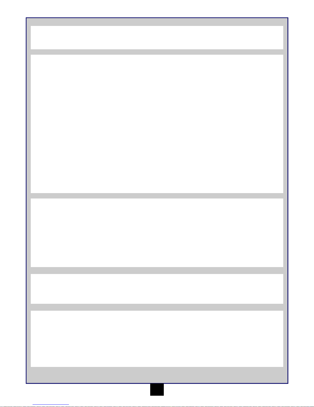
Table of contents
Page
Warranty 1
Specifications 2
Recommended Tools 2
Safety Precautions 2
Items required for operation 2
Charging the battery pack 2
Transmitter 3
Installing the battery pack 4
Turning on the power 4
Turning off the power 4
Trim Setup 4
Electronic Speed Control Setup 4
Driving 5
Trouble Shooting 5
Maintenance after driving 5
Parts Listing 6
Exploded Diagram iON XB 25
Exploded Diagram iON XT 26
Exploded Diagram iON MT 27
Exploded Diagram iON SC 28
HAVE FUN! But please read this first !!
We know you will have great fun with your model, but to get the best from your purchase please read this information BEFORE you operate the
model.
1
90 Day Component Warranty
We want you to enjoy your purchase, but please read this first!
This product is covered by a 90 day component warranty from date of purchase. If any part of the product fails as a result of faulty manufacture
during this period then we will repair or replace that part at our discretion.
We do not operate a new for old warranty once the product has been used.
Please note this product is not a toy and it is recommended that children 14 and under are supervised by an adult. It is the responsibility of the
parent or guardian to ensure minors are given appropriate guidance and supervision.
If you suspect there is a problem with the product, for whatever reason, it is the user’s responsibility to investigate and take steps to rectify the
problem before further damage occurs.
Not Covered By Warranty
This is a sophisticated, high performance model and should be treated with care and respect. Every effort has been made to make this product as
strong and durable as possible, however due to the nature of this product, it is still possible to break or damage parts through crashing or extreme
use. Components damaged as a result of crash damage, improper use, lack of maintenance or abuse is not covered by the warranty.
How to Claim Against your Warranty
For warranty claims please first contact your supplying retailer. Do not return the product to your distributor without their prior approval. You may
not need to return the product in full, only the damaged component along with a copy of your purchase receipt. In many cases it is faster and more
cost effective for the user to fit the replacement part(s) to the product & therefore we reserve the right to supply parts only in these instances.
Any returned component that is inspected by your distributor and found to have an invalid warranty claim may be subject to an inspection and
handling fee before it can be returned. Any repairs required as a result of neglect or misuse will be charged before any work is carried out on the
product. If you decide not to have any work carried out the distributor reserves the right to charge a handling and a shipping fee.
Please attach your proof of purchase in the manual as you may need it again in the future.
Page 3
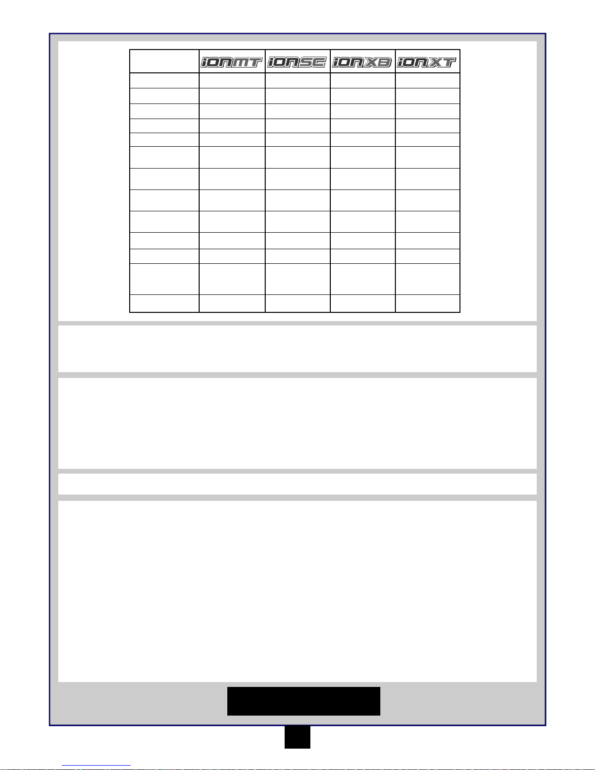
Specifications
2
Safety precautions
This product is an authentic radio controlled vehicle (RC vehicle) and it is not a toy. Read and understand this instruction manual thoroughly
before running the model. If you are not familiar with RC vehicles, we recommend that you ask someone familiar with RC vehicles for advice.
Never connect the rechargeable drive battery in the reverse polarity or disassemble the battery. If the drive battery is used in the wrong way, high
current can be generated and it is very dangerous.
Never run RC models near people or animals, or on public streets or highways. This could cause serious accidents, personal injuries, and/or
property damage.
Recommended Tools
These tools are not included with the product but are recommended for use whilst working with this vehicle
Scissors, Mini Screwdrivers, Hexagonal Screwdrivers 1.5mm, 2.0mm, 2.5mm, 3.0mm, 4-Way Cross Wrench (Small), 4-Way Cross Wrench
(Large), Side Cutters, Needle Nose Pliers
Items required for operation
4 * AA Batteries for the Transmitter
Length
255mm 258mm 249mm 255mm
Width
185mm 182mm 174mm 182mm
Height
105mm 100mm 95mm 97mm
Wheel base
165mm 165mm 165mm 165mm
Drive System
4wd Shaft Drive 4wd Shaft Drive 4wd Shaft Drive 4wd Shaft Drive
Gear Ratio
8.75:1 8.75:1 8.75:1 8.75:1
Ground
Clearance
22mm 22mm 22mm 22mm
Diameter of
wheel
47mm 47mm 47mm 47mm
Width of wheel
27mm 27mm 27mm 27mm
Motor
MM-28 370 size MM-28 370 size MM-28 370 size MM-28 370 size
Servo
Maverick MS-28 Maverick MS-28 Maverick MS-28 Maverick MS-28
2 in 1 ESC/RX
MSRS-28 2 in 1
Fwd/Rev ESC/RX
MSRS-28 2 in 1
Fwd/Rev ESC/RX
MSRS-28 2 in 1
Fwd/Rev ESC/RX
MSRS-28 2 in 1
Fwd/Rev ESC/RX
Battery
MBP-28 800mAh
Ni-MH
MBP-28 800mAh
Ni-MH
MBP-28 800mAh
Ni-MH
MBP-28 800mAh
Ni-MH
Charging the battery pack
Always use the included charger for the included battery pack. Charging time for an empty battery pack is about 3 hours. Do not charge the
battery pack longer than 3 hours to avoid overheating and battery damage.
Cautions
• This charger can be used only for the battery pack included in this kit.
• Do not charge the battery pack for longer than 3 hours. Overcharging generates excessive heat and will damage the battery pack.
• Use the charger with adult supervision. Do not use the charger near water or when wet.
• Do not use the charger if the wire is frayed or worn. If the wire is frayed or worn a short circuit can cause a fire or burns.
• If you are not sure about the level of the battery pack before charging use it in the vehicle until the vehicle slows, leave to cool and then
recharge.
1. Select your regions electrical mains plug and attach it to the charger. Always use the correct mains plug version for your country.
2. Connect the charging socket to the supplied battery packs power plug. The connectors are sided and have a clip to secure it in place. Do
not force together and always check you have the connection the right way round.
3. The charger will automatically start to charge your battery pack. Do not leave connected for more than 3 hours on a flat battery pack and
always observe the cautions above.
DISCONNECT THE BATTERY
PACK AFTER USE!
Page 4
3
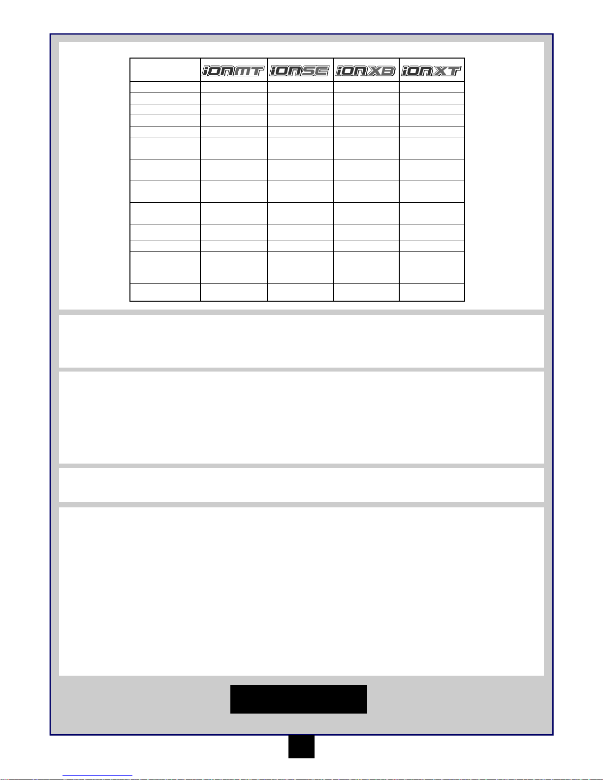
Transmitter
Your Transmitter is an advanced controller designed for the beginner to be easy to use and tune. You will need to follow the steps below to ensure
you prepare the controller correctly for use and understand the adjustment possibilities available.
Turning on the power
Turn on transmitter first and then turn on receiver.
Turn on the transmitter switch and the LED battery indicator will light up.
Turn on the receiver. The automatic set-up of the factory set speed control should
have been completed. If you experience any problems with the speed control settings refer to the Electronic Speed Control Section for correct
setup information.
Preparing the transmitter
Open the battery holding tray to expose the
empty battery slots.
Insert 4 AA batteries into the marked spaces.
Please note the correct direction of the
batteries
Incorrect battery insertion could lead to
damage
The function switches on the transmitter
1. Throttle Trim
2. Steering Trim
3. Power Switch
4. Steering End Point
dials (left/right lock)
5. Throttle End Point
dials (low/high points)
6. Steering reverse
switch
7. Throttle reverse switch
8. Power LED’s
9. Steering Control
10. Throttle Trigger
11. France Mode Switch
12. Charging Port
13. Throttle Neutral
Position switch
1
5
9
10
Throttle Trigger
2
1
Neutral
1. Push the trigger
forward to Reverse
2. Pull the trigger
backwards to go
forwards and speed up
L
R
Turn the steering wheel to
the left or right to make the
vehicle turn left or right
Dual Rates
The dual rate settings allow you to
adjust the maximum degree of
movement from the servo or ESC on
that channel.
10 is full movement. 0 (Zero) is very
little movement.
2
3
6
4
7
8
11
12
13
Steering Wheel
1 2 1 2
Steering Trim
1. Turn anti clockwise to trim to the
left
2. Turn clockwise to trim to the right
Throttle Trim
1. Turn anti clockwise for more
brake
2. Turn clockwise for more
throttle
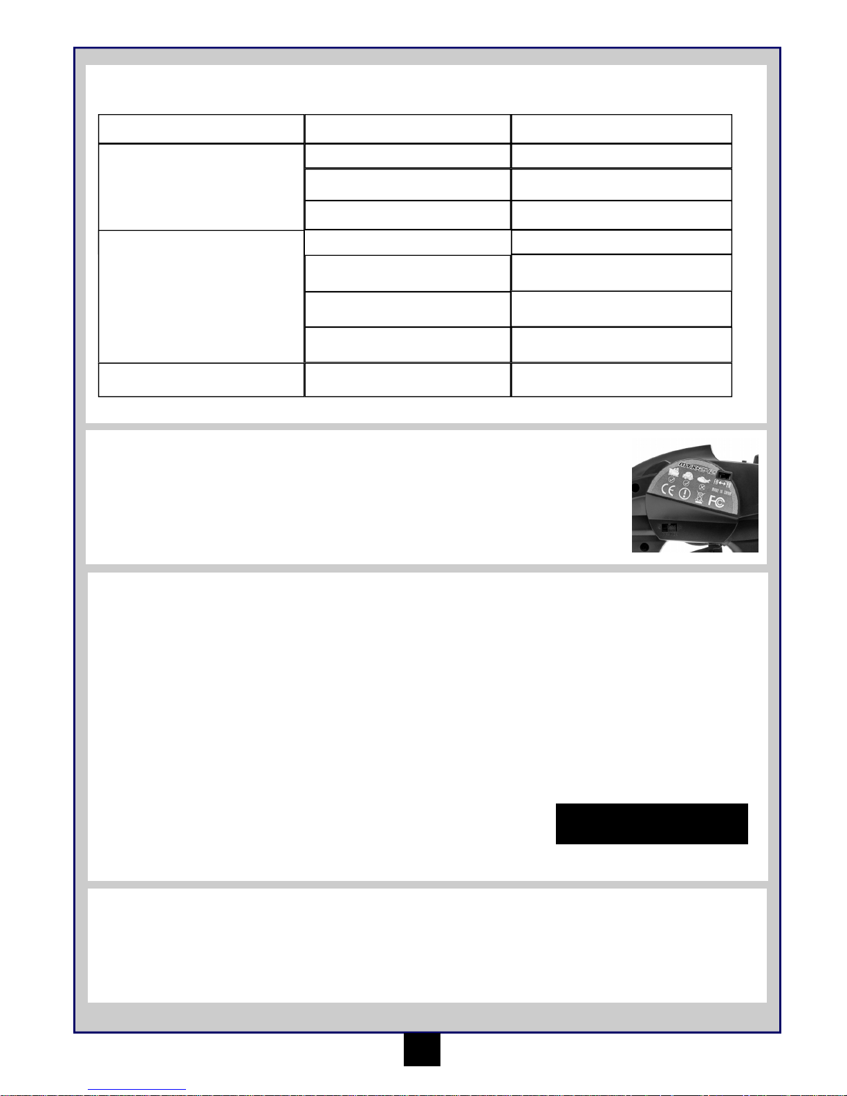
2.4Ghz technology has done away with the need for long extendable
aerials. The Aerial on your transmitter is located internally
Binding the Transmitter and Receiver
You may need to setup your transmitter to ‘bind’ with the receiver if you change to a new receiver or for any reason lose signal.
Please make sure the “French Mode” switch on the Transmitter is in the “FR” position. The receiver will ONLY automatically bind with the
transmitter if the switch in the “FR” position.
• Turn on the Receiver power.
• Press the “SW” button on the Receiver. The Receiver LED should start flashing.
• Turn on the Transmitter
• When the Receiver LED becomes solid the binding process is completed.
Page 5

4
Installing the battery pack
You need to insert the
battery pack in the open
section for the battery. Use
the strap provided to place
on top of the battery and
then use the retaining clip
to secure the battery.
Once fastened and
secured please connect
the battery plug into the
speed controller plug
noting correct polarity. Red
to red, black to black.
Turning off the power
Turn off receiver first and then turn off transmitter.
If you switch off the transmitter first before the R/C car, you may lose control of the R/C car.
• Turn off the receiver switch.
• Turn off the transmitter switch.
• Disconnect the battery connector from the speed control connector.
Trim Setup
If the front tyres are not pointing straight forward with the transmitter on, adjust the steering trim. Then if needed make fine adjustments with the
steering trim whilst driving the vehicle.
If wheels point left, turn clockwise If wheels point right, turn anti-clockwise. If they point straight no adjustment required.
DISCONNECT THE BATTERY
PACK AFTER USE!
Electronic Speed Control Setup
MSRS-28 - 2 in 1 Receiver/ESC 2.4GHz
1. With the speed control switch set to off, plug in a suitable battery pack.
2. With the transmitter switched on and throttle trim set to the centre, turn on the speed control.
3. To indicate the speed control is working correctly its LED will light constantly followed by 3 beeps
4. If necessary adjust the throttle trim of the transmitter so your car is stationary with no throttle or brake applied.
5. Your speed control is fully installed and ready to use.
Features
• 6.0Volt — 8.4Volt Power Input
• Waterproof
• High Frequency Drive System
• Forward, Reverse & Brake Linear
Operation
• Automatic Setup System
• Over Current Protection
• Thermal Protection
• Low Voltage Protection
• LED with audible beep
Technical Information
• 20A drive FET’s & 15A Reverse FET’s
• Case dimensions: 70mm*33mm*24mm
• Silicone Wire 22 Gauge
• Weight 25g with connectors and switch
• BEC Voltage 6.0V
Page 6
5
Trouble Shooting
Please read this section if you have any fault trying to operate the vehicle
If you encounter any other fault whilst operating the vehicle please contact your local hobby shop or alternatively contact your local distributor.
Problem Cause Remedy
The vehicle does not move
The vehicle does not follow your driving
inputs
Transmitter or receiver is off
Batteries are not placed correctly in the
The main battery is not charged enough
Transmitter or receiver is off
Transmitter reverse switches are set
incorrectly
Transmitter End Point Adjustments (EPA)
are set incorrectly
Turn on both the transmitter and receiver
Place batteries in the transmitter properly
Charge the main battery
Turn on both the transmitter and receiver
Check the reverse switch settings
Check that your EPA Dials on your
transmitter.
The front and rear wheels rotate in
opposing directions
Incorrect user differential placement Insert the differential the correct way
Weak batteries in either the transmitter or
the car
Replace batteries in the transmitter and recharge the main battery.
Maintenance after driving
Proper maintenance is very important. Make sure to always perform appropriate maintenance after driving so that you can enjoy driving without
problems next time.
Completely remove all dirt and debris from the vehicle, especially in the suspension, drive shafts and steering parts. Inspect each part and screw
for loosening, missing or damages.
You should always make sure your wheels are tight and parts move freely after and before use.
France Mode
The Transmitter has a switch labelled “France Mode” “FR-EU”.
Please make sure the “French Mode” switch on the Transmitter is in the “FR” position. The receiver will ONLY auto-
matically bind with the transmitter if the switch in the “FR” position.
Please note: Switching from or to “France mode” clears the binding settings. Follow the instructions on how to reset
these in these instructions.
Driving
Driving an R/C car can be very difficult to master but here are some basic tips to help you to understand how to use it before you have your first
attempt
• Drive the vehicle in a very large space, especially until you get the feel of driving the product.
• Do not run on public streets or highways. This could cause serious accidents, personal injuries and/or property damage.
• Do not run in water or sand.
• If you keep pulling the throttle trigger on the transmitter, the vehicle will keep accelerating and run very fast. It is difficult to steer the
vehicle running at high speed until you become used to driving. Drive the vehicle slowly by pulling the throttle trigger to the fullest and
quickly releasing it.
You can turn the vehicle right or left while it is running.
When the vehicle is running toward you, you need to operate the steering wheel in the opposite direction to the operation when the vehicle is
running away from you.
Practice turning the vehicle, referring to the following:
Rather than just paying attention to the direction of the steering wheel, imagine that you are at the centre of the steering wheel, looking ahead of
the vehicle, to turn in the direction you like.
Once you become conformable driving the vehicle, practice driving on a track with cones.
Keep practising until you feel comfortable with the steering, throttle and brake at low speeds.
Once you are feeling comfortable try using reverse.
When you have mastered the basics you will be able to drive at higher speeds in a more controlled fashion.
DISCONNECT THE BATTERY
PACK AFTER USE!
Page 7
6
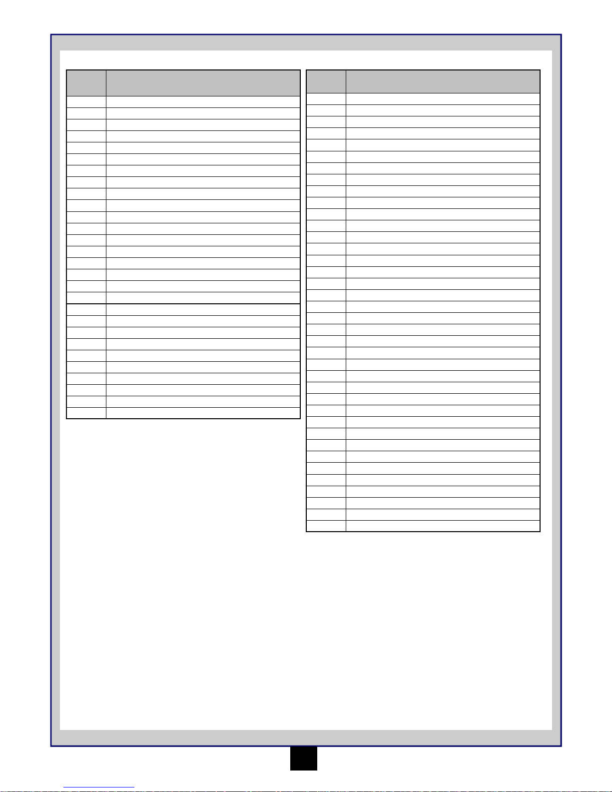
Parts Listing (For Exploded diagram see Pages 25-28)
Part
Number
Description
MV22029 Body Clips (8Pcs) (ALL Strada and EVO)
MV22711 MTX - 242 2.4 GHz 2Ch Transmitter
MV24041 Charger 4.8-8.4V Ni-MH Batt.(AC110/220V MultiPlug)
MV25032 E-Clip M2.5 (8pcs)
MV25034 Nyloc Nut M2.5 (8pcs)
MV25037 Button Head Screw M3x8 (8pcs)
MV28001 Main Composite Chassis (ALL Ion)
MV28002 Complete Shock Absorber 2Pcs (ALL Ion)
MV28003 Steering Arms 2Pcs (ALL Ion)
MV28004 Rear Hub Carrier 2Pcs (ALL Ion)
MV28005 Front Castor Block 2Pcs (ALL Ion)
MV28006 Suspension Arm Fr or Rr 2Pcs (ALL Ion)
MV28007 Wheel Axle 2Pcs (ALL Ion)
MV28008 Dogbones 2Pcs (ALL Ion)
MV28009 Steering Ackermann Link 1Pc (ALL Ion)
MV28010 Motor Mount & Gear Cover 1Pc (ALL Ion)
MV28011 Composite Top Deck & Shock Towers 1Pc (ALL Ion)
MV28012 Differential Case 1Pc (ALL Ion)
MV28013 Spur Gear 45 Tooth 1Pc (ALL Ion)
MV28014 Plastic Pinion Gear 13 Tooth 2Pcs (ALL Ion)
MV28015 Crownwheel & Pinion Gear 1Pc (ALL Ion)
MV28016 Complete Gear Diff. Fr or Rr (ALL Ion)
MV28017 Steering Link Set (ALL Ion)
MV28018 Composite Diff. Outdrives 2Pcs (ALL Ion)
MV28019 Servo Saver Set (ALL Ion)
MV28020 Battery Cover 1Pc (ALL Ion)
MV28021 Centre Driveshaft (ALL Ion)
MV28022 Main Bumper Fr & Rr 2Pcs (ALL Ion)
Part
Number
Description
MV28023 Ball Stud 2.5x4.5mm 6Pcs
MV28024 Pin 2x22mm 6Pcs
MV28025 Pin 1.5x16mm 6Pcs
MV28026 Lower Hinge Pin Fr & Rr 2 Pcs (ALL Ion)
MV28027 5 Spoke Black Wheels 2 Pcs (ALL Ion)
MV28028 Ball Bearing 8 x 12 x 3.5mm 6Pcs
MV28029 Ball Bearing 4 x 8 x 3mm 6Pcs
MV28030 Ball Bearing 10 x 6 x 3mm 8Pcs
MV28031 Diff. Gear Set (ALL Ion)
MV28032 Button Head Screw M2.5 x 20mm 6Pcs
MV28033 Button Head Screw M2.5 x 14mm 6Pcs
MV28034 Button Head Screw M2.5 x 10mm 6Pcs
MV28035 Button Head Screw M2.5 x 8mm 6Pcs
MV28036 Button Head Screw M2.5 x 6mm 6Pcs
MV28037 Flat Head Screw M3 x 6mm 6Pcs
MV28038 Cap Head Screw M2 x 6mm 6Pcs
MV28039 Flat Head Screw M2 x 8mm 6Pcs
MV28040 Grub Screw M3 x 3mm 6Pcs
MV28041 Flanged Lock Nut M3 6Pcs
MV28042 Short 2.4 GHz Black Antenna Pipe 3Pcs
MV28046 Truck Painted Body Blue (Ion XT)
MV28047 1/18 Truggy Wheel & Tyre Assembly (Ion XT)
MV28048 Large Bumper 1Pc (Ion MT)
MV28049 Body Post 2Pcs (Ion XB)
MV28050 Buggy Painted Body Blue (Ion XB)
MV28051 Composite Rear Wing (Ion XB)
MV28052 1/18 Buggy/SC Wheel & Tyre Assembly (Ion XB/SC)
MV28053 Short Course Painted Body Blue (Ion SC)
MV28054 Monster Truck Painted Body Blue (Ion MT)
MV28055 1/18 Monster Truck Wheel & Tyre Assembly (Ion MT)
MV28056 MSRS - 28 2 in 1 Receiver/ESC 2.4GHz
MV28057 MBP - 28 7.2V 800mAh Ni-MH Battery
MV28058 MM - 28 370 Motor
MV28059 Battery Connector Adapter Tamiya to Mini Tamiya
MV28060 Servo Horn & Screw (ALL Ion)
MV28061 MS - 28 Servo
MV28043 Metal Pinion Gear 14 Tooth 2Pcs (ALL Ion)
MV28044 Metal Pinion Gear 13 Tooth 2Pcs (ALL Ion)
Page 8
Sommaire
Page
Garantie 7
Spécification 8
Outils recommandés 8
Précautions de sécurité 8
Éléments nécessaires au bon fonctionnement 8
Charge de la batterie 8
Émetteur 9
Installation du bloc -piles 10
Mise en marche 10
Arrêt 10
Configuration du compensateur 10
Régulateur de vitesse électronique 10
Conduite 11
Dépistage des pannes 11
Entretien après la conduite 11
Liste des pièces 12
Vue éclatée iON XB 25
Vue éclatée iON XT 26
Vue éclatée iON MT 27
Vue éclatée iON SC 28
7
AMUSEZ-VOUS ! Mais lisez ceci d’abord !!
Nous savons que vous allez bien vous amuser avec votre modèle, mais pour obtenir le meilleur de votre achat, veuillez lire cette information
AVANT de le mettre en marche.
Garantie du composant de 90 jours
Nous souhaitons que vous profitiez de votre achat, mais lisez ceci d’abord !
Ce produit est couvert par une garantie composant de 90 jours à partir de la date d’achat. Si, pendant cette période, l’une des pièces du produit a
un défaut de fabrication, nous la réparerons ou la remplacerons à notre choix.
Nous ne donnerons pas de nouvelle garantie pour une ancienne, une fois que le produit a été utilisé.
Veuillez remarquer que ce produit n’est pas un jouet, et qu’il est recommandé aux moins de 14 ans sous la surveillance d’un adulte. Il est de la
responsabilité des parents ou tuteur de garantir que les mineurs ont l’aide et la supervision nécessaires,
Si vous pensez qu’il existe, pour toute raison, un problème avec le produit, il est de la responsabilité de l’utilisateur de rechercher et de suivre les
pas afin de corriger le problème avant de causer de plus grands dommages.
Non couvert par la garantie
Ceci est un modèle sophistiqué et de haute performance et devra être traité avec soin et respect. Tous les efforts ont été faits pour rendre ce
produit aussi fort et durable que possible, toutefois, il est possible de casser ou d’endommager des pièces après un choc ou un usage extrême.
Les composants endommagés suite à une collision, un usage incorrect, un manque d’entretien ou des mauvais traitements ne sont pas couverts
par la garantie.
Comment revendiquer votre garantie
Pour les droits de garantie, veuillez prendre d’abord contact avec votre fournisseur. Ne renvoyez pas le produit à votre distributeur sans leur
accord préalable. Vous n’avez pas à renvoyer le produit en entier, mais seulement le composant endommagé avec une copie de votre bon
d’achat. Dans beaucoup de cas, il est plus rapide et rentable pour l’usager de monter le(s) pièce(s) de rechange sur le produit et dans ce cas,
nous nous réservons le droit de ne fournir des pièces que dans ce cas.
Tout composant retourné et inspecté par notre distributeur ne possédant pas une garantie valable, peut être sujet à des frais d’inspection et de
manipulation avant sa réexpédition. Toutes les réparations nécessaires suite à une négligence ou mauvaise utilisation seront facturées avant le
début de tout travail sur le produit. Si vous décidez de ne réaliser aucun travail, le distributeur se réserve le droit de facturer des frais de
manipulation et d’expédition.
Veuillez joindre votre preuve d’achat à ce manuel car vous pourrez en avoir besoin à l’avenir.
Page 9
Specifications
8
Éléments obligatoires pour le fonctionnement - 4 * piles AA pour l’émetteur
Outils recommandés
Ces outils ne sont pas fournis avec le produit mais leur utilisation est recommandée pour travailler avec ce véhicule
Ciseaux, mini tournevis, Pinces a bec effile, Tounevis hexagonaux 1.5mm, 2.0mm, Cle en croix (petite, Pinces coupantes de cote.
Mesures de sécurité
Ce produit est un vrai véhicule radiocommandé et ce n’est pas un jouet. Lisez avec attention ce manuel d’instructions avant de mettre le modèle
en marche. Si vous n’êtes pas familiarisé avec les véhicules radiocommandés, nous vous recommandons de demander le conseil pour qui cela
est familier.
Ne connectez jamais la batterie de traction rechargeable en inversant les pôles ni ne démontez la batterie. Si la batterie de traction est utilisée en
sens inverse, un courant élevé peut être engendré et cela est très dangereux.
Ne mettez jamais des modèles radiocommandés en marche près de personnes ou d’animaux, ou dans des lieux publics. Cela peut provoquer des
accidents sérieux, des blessures, et/ou des dommages matériels.
Charge de la batterie
Utilisez toujours le chargeur fourni pour la batterie qui est incluse. Le temps de charge d’une batterie vide est d’environ 3 heures. Ne chargez pas
la batterie pendant plus de 3 heures afin d’éviter une surchauffe et l'endommagement de la batterie.
Précautions
• Ce chargeur ne peut être utilisé que pour la batterie livrée dans ce kit.
• Ne chargez pas la batterie pendant plus de 3 heures. La surcharge engendre une chaleur excessive qui endommagera la batterie.
•
Utilisez le chargeur sous la supervision d'un adulte. N'utilisez pas le chargeur à proximité d'un point d'eau ni dans un lieu humide.
•
N’utilisez pas le chargeur si le câble est effiloché ou usé. Si le fil est effiloché ou usé, il peut se produire un court-circuit pouvant provoquer un
incendie ou des brûlures.
Si vous n'êtes pas certain de l'état de la batterie avant de la charger, utilisez-la dans le véhicule jusqu'à ce que celui-ci s'affaiblisse, laissez-le
refroidir puis rechargez la batterie.
1. Sélectionnez votre bougie selon le réseau électrique de votre région et fixez-la au chargeur. Utilisez toujours la version de bougie adéquate à
votre pays.
2. Connectez la prise du chargeur à la prise d’alimentation de la batterie fournie. Les connecteurs sont sur le côté et possède une fixation pour
l’assurer en place. Ne les forcez pas et vérifiez toujours que la connexion est bien effectuée.
3. Le chargeur démarrera automatiquement à charger votre batterie. Ne laissez pas une batterie à plat connectée pendant plus de 3 heures et
observez toujours les avertissements ci-dessus.
Longueur
255mm 258mm 249mm 255mm
Largeur
185mm 182mm 174mm 183mm
Hauteur
105mm 100mm 95mm 97mm
Empattement
165mm 165mm 165mm 165mm
Entraînement
4x4 Entraînement arbre 4x4 Entraînement arbre 4x4 Entraînement arbre 4x4 Entraînement arbre
Rapport de
vitesse
8.75:1 8.75:1 8.75:1 8.75:1
Garde au sol
22mm 22mm 22mm 22mm
Diamètre de
roue
47mm 47mm 47mm 47mm
Largeur de
roue
27mm 27mm 27mm 27mm
Moteur Taille
MM-28 370 size MM-28 370 size MM-28 370 size MM-28 370 size
Servo
Maverick MS-28 Maverick MS-28 Maverick MS-28 Maverick MS-28
2 in 1 ESC/RX
MSRS-28 2 in 1
Avt /Arr ESC/RX
MSRS-28 2 in 1
Avt /Arr ESC/RX
MSRS-28 2 in 1
Avt /Arr ESC/RX
MSRS-28 2 in 1
Avt /Arr ESC/RX
Piles
MBP-28 800mAh
Ni-MH
MBP-28 800mAh
Ni-MH
MBP-28 800mAh
Ni-MH
MBP-28 800mAh
Ni-MH
DEBRANCHEZ LE BLOC
BATTERIE APRES UTILISATION !
Page 10
9
Émetteur
Votre émetteur est un régulateur avancé conçu pour faciliter l’utilisation et le réglage pour le débutant. Vous devrez suivre les étapes ci-dessous
pour vous assurer que vous avez préparé correctement le régulateur et que vous avez compris les possibilités disponibles de réglage.
Préparation de l’émetteur
Ouvrez la plaque de retenue des piles pour
découvrir les fentes des piles vides.
Insérez 8 piles AA dans les espaces marqués
à cet effet. Veuillez faire attention au sens
correct des piles.
L’insertion incorrecte des piles peut pro-
Votre émetteur est un régulateur avancé conçu pour faciliter l’utilisation et le réglage pour le débutant. Vous devrez suivre les étapes ci-dessous
pour vous assurer que vous avez préparé correctement le régulateur et que vous avez compris les possibilités disponibles de réglage.
Les commandes de fonction de l’émetteur
1. Compensation des gaz
2. Compensateur de
direction
3. Interrupteur d'alimentation
4. Cadrans d’extrémité de
direction (verrouillage
gauche/droite)
5. Cadrans d’extrémité
d'accélération (points
bas/élevés)
6. Interrupteur marche arrière direction
7. Interrupteur marche arrière accélérateur
8. LED d'alimentation
9. Commande de direction
(roue)
10. Enclencheur des gaz
11. Commutateur mode
France
12. Port de chargement
13. Commutateur position
neutre accélérateur
1
5
9
10
Commande d’accélérateur
2
1
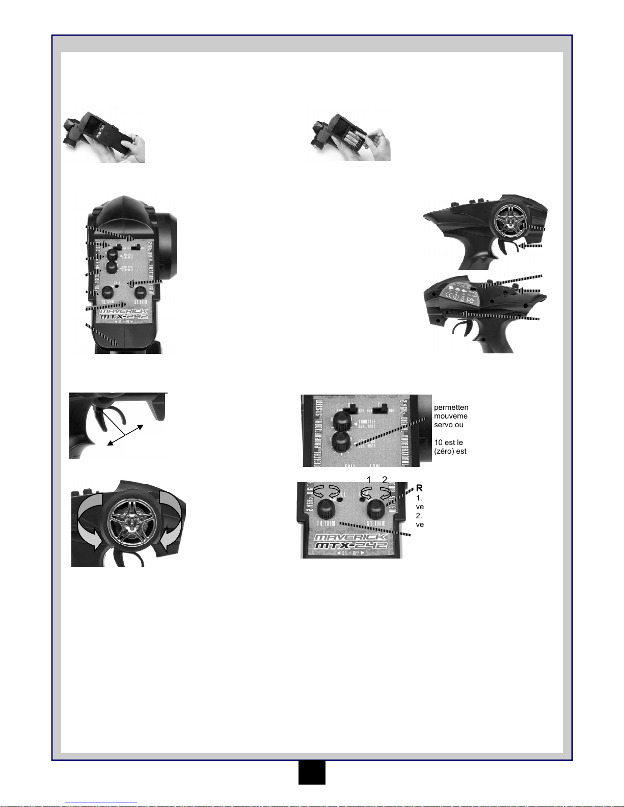
1. Poussez l’enclencheur
vers l’avant pour la
marche arrière
2. Tirez l’enclencheur
vers l’arrière pour
avancer et accélérer
L
R
Tournez la roue directrice
vers la gauche ou la droite
pour que le véhicule aille
dans cette direction.
Cadrans d’extrémité
Les réglages à double taux vous
permettent de régler le degré de
mouvement maximum du dispositif
servo ou ESC sur ce canal.
10 est le mouvement complet. 0
(zéro) est un très petit mouvement.
2
3
6
4
7
8
11
12
13
Roue directrice
1 2 1 2
Régulateur de direction
1. Tournez vers la gauche pour orienter
vers la gauche.
2. Tournez vers la droite pour orienter
vers la droite.
Point Mort
La technologie 2.4Ghz a éliminé la nécessité de disposer de longues
antennes extensibles. L'antenne de votre transmetteur est située à
l'intérieur de celui-ci.
Associer le transmetteur et le récepteur
Vous devrez peut-être régler votre transmetteur afin qu'il 's'associe' au récepteur si vous utilisez un nouveau récepteur ou si vous perdez le signal,
pour quelque raison que ce soit.
Veuillez vous assurer que le commutateur « Mode français » sur le Transmetteur est en position « FR ».
Le récepteur ne s'associera automatiquement au transmetteur QUE si le commutateur est en position « FR ».
• Allumez l'alimentation du récepteur.
• Appuyez sur le bouton «SW» du récepteur. La LED du récepteur devrait commencer à clignoter.
• Allumez le transmetteur.
• Lorsque la LED du récepteur devient fixe, le processus d'association est terminé.
Régulateur d’accélérateur
1. Tournez vers la gauche pour freiner
plus fort.
2. Tournez vers la droite pour accélérer
plus fort.
Mise en marche
Allumez d’abord l’émetteur puis le récepteur.
Allumez l’émetteur et l’indicateur de batterie Del s’allume.
Allumez le récepteur. La configuration automatique du contrôle de vitesse ajusté en usine devra être finie. Si vous rencontrez des problèmes avec
les paramètres de contrôle de la vitesse, reportez-vous à la partie de Contrôle de vitesse électronique pour une information adéquate de
configuration.
Page 11

10
Installation du bloc -piles
Vous devez insérer le
bloc-piles dans la partie
ouverte de la batterie.
Utilisez la barrette fournie
pour mettre sur les piles,
puis utilisez les deux
agrafes de retenue pour
assurer les piles.
Une fois serrée et assurée,
veuillez connecter la fiche de
la batterie dans la fiche du
régulateur de vitesse Vérifiez
l’exactitude de la polarité.
Rouge avec rouge, noir avec
noir.
Arrêt
Éteignez d’abord le récepteur puis l’émetteur.
Si vous éteignez l’émetteur avant la voiture radiocommandée, vous pouvez perdre le contrôle de la voiture.
• Éteignez l’interrupteur du récepteur.
• Éteignez l’interrupteur de l’émetteur
• Déconnectez le connecteur des piles du connecteur de contrôle de vitesse.
Configuration du compensateur
Si les pneus avant ne sont pas orientés vers l’avant avec l’émetteur en marche, ajustez le régulateur de direction. Puis au besoin, effectuez des
réglages plus précis avec le régulateur de direction tout en conduisant le véhicule.
Si elles vont tout droit, aucun réglage n’est à
réaliser.
Si les roues vont vers la gauche, tournez
à droite.
Si les roues vont vers la droite, tournez à
gauche.
Régulateur de vitesse électronique
MSRS-28 - 2 in 1 Receiver/ESC 2.4GHz
1. Contrôler que l’interrupteur est sur OFF lorsque vous branchez la batterie
2. Vous allumez la radio et gardez la gâchette des gaz au neutre. Ensuite, vous allumez le régulateur électronique.
3. Pour indiquer que le contrôle de la vitesse fonctionne correctement, sa LED s'allumera de manière fixe puis elle émettra 3 bips
4. Si nécessaire, ajustez le trim des gaz à votre ra dio de manière à arrêter votre voiture au neutre.
5. Votre régulateur est réglé et prêt à être utiliser.
Caractéristiques
• Entrée alimentation 6.0 Volts —
8.4Volts
• Etanche
• Système de conduite haute
fréquence
• Marche avant, arrière et frein
linéaire Fonctionnement
• Système de configuration
automatique
• Protection surintensité
• Protection thermique
• Protection basse tension
• Del avec bip sonore
• 20 Limites de tour du 370 moteur brosse
Information technique
• Entraînement TEC 20 A et TEC Arrière
10 A
• Dimensions caisse : 70mm*33mm*24mm
• Jauge à fils en silicone 22
• Poids 25g avec connecteurs et
commutateur
• Tension 6V centre électrique à bus
DEBRANCHEZ LE BLOC
BATTERIE APRES UTILISATION !
Page 12

11
Conduite
La conduite d’une voiture radiocommandée peut être très difficile à maîtriser mais voici certains trucs de base pour vous aider à comprendre
comment l’utiliser avant votre première tentative.
• Conduisez le véhicule dans un endroit très grand, jusqu’à ce que vous ressentiez la conduite de ce produit.
• Ne mettez pas en marche dans des endroits ou voies publics. Cela peut provoquer des accidents sérieux, des blessures, et/ou des
dommages matériels.
• Ne faites pas marcher dans le sable ou l’eau.
• Si vous maintenez le déclencheur d’accélération de l’émetteur, le véhicule accélérera de plus en plus et ira très vite. Il est difficile de
manœuvrer le véhicule à grande vitesse jusqu’à ce que vous utilisiez l’entraînement. Conduisez doucement le véhicule en tirant le
déclencheur d’accélération à fond et en le relâchant aussitôt.
Vous pouvez faire tourner le véhicule à droite ou à gauche pendant son fonctionnement.
Lorsque le véhicule avance vers vous, vous devez mettre la roue directrice en sens inverse à sa marche lorsque il s’éloigne de vous.
Exercez-vous à faire virer le véhicule en vous reportant à ce qui suit :
Plutôt que de ne prêter attention qu’au sens de la roue directrice, imaginez que vous êtes au centre de la roue directrice, en regardant face au
véhicule pour tourner dans le sens que vous souhaitez.
Une fois que vous vous sentez à l’aise pour conduire le véhicule, exercez-vous à conduire sur une piste avec des cônes.
Continuez à pratiquer jusqu’à ce que vous vous sentiez à l’aise avec la direction, l’accélération et le frein à de basses vitesses.
Une fois que vous êtes à l’aise, essayez en marche arrière.
Lorsque vous maîtrisez les bases, vous serez capable de conduire à de plus grandes
vitesses d’un mode contrôlé.
Entretien après la conduite
Un entretien adéquat est très important. Réalisez toujours un entretien adéquat après la conduite pour que vous puissiez profiter de la conduite
sans aucun problème la fois suivante.
Enlevez complètement toute saleté et tout débris du véhicule, surtout des suspensions, des arbres de transmission et des pièces de direction.
Inspectez chaque pièce et vis contre tout desserrement, absence ou dommages.
Vous devrez toujours vérifier que vos roues sont bien serrées et que les pièces possèdent un mouvement libre avant et après chaque utilisation.
Mode France
Le transmetteur et le récepteur ont tous deux un commutateur portant le nom "France Mode" "FR-EU".
Veuillez vous assurer que le commutateur « Mode français » sur le Transmetteur est en position « FR ».
Le récepteur ne s'associera automatiquement au transmetteur QUE si le commutateur est en position « FR ».
Remarque : Le passage en mode France ou UE supprime la connexion et les paramètres de sûreté intégrée. Suivez les
instructions pour procéder
Dépannage
Veuillez lire cette partie si vous rencontrez un défaut en essayant de faire marcher votre véhicule.
Si vous rencontrez un autre défaut lors du fonctionnement du véhicule, veuillez prendre contact avec votre magasin de modélisme local ou avec
notre distributeur local.
Problème Cause Solution
Le véhicule ne bouge pas
Le véhicule ne suit pas vos commandes
de conduite
L’émetteur ou le récepteur est éteint
Les piles ne sont pas correctement
installées dans l’émetteur
La batterie principale n’est pas assez
chargée
L’émetteur ou le récepteur est éteint
Les interrupteurs inverses de l’émetteur
sont mal réglés
Les ajustements d’extrémité (EPA) de
l’émetteur sont mal ajustés
Allumez l’émetteur et le récepteur
Mettez correctement les piles dans l’émetteur
Chargez la batterie principale
Allumez l’émetteur et le récepteur
Vérifiez les paramètres de l'interrupteur
inverse
Vérifiez les cadrans d’EPA de votre émetteur
Les roues avant et arrière tournent dans
des directions opposées
Emplacement différentiel de l’usager
incorrect
Insérez dans le bon sens le différentiel
Fuite des piles de l'émetteur et du
récepteur
Installez de nouvelles piles
DEBRANCHEZ LE BLOC
BATTERIE APRES UTILISATION !
Page 13

12
Liste des Pièces (Pour le diagramme éclaté voir les pages 25-28)
Numéro
de
pièce
Description
MV22029 Pinces carrosserie (8Pcs) (TOUTES Strada et EVO)
MV22711 Transmetteur MTX - 242 2.4 GHz 2Ch
MV24041 Chargeur 4.8-8.4V Ni-MH Batt.(AC110/220V MultiPlug)
MV25032 E-Clip M2.5 (8pcs)
MV25034 Ecrou Nyloc M2.5 (8pcs)
MV25037 Vis à tête ronde M3x8 (8pcs)
MV28001 Châssis composite principal (TOUT Ion)
MV28002 Amortisseur complet 2Pcs (TOUT Ion)
MV28003 Bras de direction 2Pcs (TOUT Ion)
MV28004 Support de moyeu arrière 2Pcs (TOUT Ion)
MV28005 Bloc Castor avant 2Pcs (TOUT Ion)
MV28006 Bras de suspension avant ou arrière 2Pcs (TOUT Ion)
MV28007 Essieu 2Pcs (TOUT Ion)
MV28008 Bobines 2Pcs (TOUT Ion)
MV28009 Articulation de direction Ackermann 1Pc (TOUT Ion)
MV28010
Couverture montage de moteur et embrayage 1Pc
(TOUT Ion)
MV28011
Plancher supérieur et tourelles de suspension composites 1Pc (TOUT Ion)
MV28012 Carter de différentiel 1Pc (TOUT Ion)
MV28013 Engrenage cylindrique 45 dents 1Pc (TOUT Ion)
MV28014
Engrenage à pignons en plastique 13 dents 2Pcs
(TOUT Ion)
MV28015
Grande couronne et engrenage à pignons 1Pc (TOUT
Ion)
MV28016
Différentiel d'embrayage complet avant ou arrière
(TOUT Ion)
MV28017 Ensemble d'articulation de direction (TOUT Ion)
MV28018 Diff. composite de dépassement 2Pcs (TOUT Ion)
MV28019 Ensemble sauve servo (TOUT Ion)
MV28020 Couvercle de batterie 1Pc (TOUT Ion)
MV28021 Arbre de transmission central (TOUT Ion)
MV28022 Pare-choc principal avant et arrière 2Pcs (TOUT Ion)
Numéro
de
pièce
Description
MV28023 Piton à rotule 2.5x4.5mm 6Pcs
MV28024 Boule d'accouplement 2x22mm 6Pcs
MV28025 Boule d'accouplement 1.5x16mm 6Pcs
MV28026
Axe de charnière inférieur avant et arrière 2 Pcs
(TOUT Ion)
MV28027 Roues noires à 5 rayons 2 Pcs (TOUT Ion)
MV28028 Roulement à bille 8 x 12 x 3.5mm 6Pcs
MV28029 Roulement à bille 4 x 8 x 3mm 6Pcs
MV28030 Roulement à bille 10 x 6 x 3mm 8Pcs
MV28031 Ensemble mécanisme de différentiel (TOUT Ion)
MV28032 Vis à tête ronde M2.5 x 20mm 6Pcs
MV28033 Vis à tête ronde M2.5 x 14mm 6Pcs
MV28034 Vis à tête ronde M2.5 x 10mm 6Pcs
MV28035 Vis à tête ronde M2.5 x 8mm 6Pcs
MV28036 Vis à tête ronde M2.5 x 6mm 6Pcs
MV28037 Vis à tête plate M2.5 x 6mm 6Pcs
MV28038 Vis à tête M2.5 x 6mm 6Pcs
MV28039 Vis à tête plate M2.5 x 8mm 6Pcs
MV28040 Vis sans tête M3 x 3mm 6Pcs
MV28041 Contre-écrou à embase M3 6Pcs
MV28042 Petit tube d'antenne noir 2.4 GHz 3Pcs
MV28046 Carrosserie de camion peinte bleue (Ion XT)
MV28047 Assemblage roue et pneu 1/18 truggy (Ion XT)
MV28048 Grand pare-choc 1Pc (Ion MT)
MV28049 Montant carrosserie 2Pcs (Ion XB)
MV28050 Carrosserie de buggy peinte bleue (Ion XB)
MV28051 Aile arrière composite (Ion XB)
MV28052 Assemblage roue et pneu 1/18 Buggy/SC (Ion XB/SC)
MV28053 Carrosserie débattement court peinte bleue (Ion SC)
MV28054 Carrosserie de Monster Truck vpeinte bleue (Ion MT)
MV28055
Assemblage roue et pneu 1/18 Monster Truck (Ion
MT)
MV28056 MSRS - 28 Récepteur/ESC 2 en 1 2.4GHz
MV28057 MBP - 28 Batterie 7.2V 800mAh Ni-MH
MV28058 MM - 28 Moteur 370
MV28059
Adaptateur pour raccordement de batterie Tamiya à
Mini Tamiya
MV28060 Klaxon et vis servo (TOUT Ion)
MV28061 MS - 28 Servo
MV28043
Engrenage à pignons en métal 14 dents 2Pcs (TOUT
Ion)
MV28044
Engrenage à pignons en métal 13 dents 2Pcs (TOUT
Ion)
Page 14

Inhaltsverzeichnis
Seite
Garantie 13
Technische Daten 14
Empfohlenes Werkzeug 14
Sicherheitsmaßnahmen 14
Für den Betrieb erforderlich 14
Batteriepack aufladen 14
Sender 15
Batteriepack einsetzen 16
Stromversorgung einschalten 16
Stromversorgung ausschalten 16
Elektronischer Geschwindigkeitsregler 16
Fahren 17
Fehlersuche 17
Wartung und Pflege nach dem Fahren 17
Teileliste 18
Explosionszeichnung iON XB 25
Explosionszeichnung iON XT 26
Explosionszeichnung iON MT 27
Explosionszeichnung iON SC 28
13
VIEL SPASS! Aber lesen Sie bitte erst diese Anleitung !!
Wir wissen, dass Sie mit Ihrem Modell viel Spaß haben weden, aber BEVOR Sie das Modell in Betrieb nehmen, lesen Sie bitte erst diese
Informationen, damit Sie das Beste aus Ihrem Kauf machen können.
90-Tage-Garantie auf Komponenten
Wir möchten, dass Sie an Ihrem Modell Spaß haben - aber lesen Sie bitte erst die nachstehenden Ausführungen!
Für dieses Produkt gilt eine 90-Tage-Garantie auf Komponenten ab dem Kaufdatum. Wenn während dieser Zeit ein Teil des Produkts infolge
Fabrikationsmängeln ausfallen sollte, liegt es in unserem Ermessen, ob wir das Teil reparieren oder austauschen.
Wenn das Produkt einmal benutzt wurde, bieten wir keine Neu-für-Alt-Garantie.
Beachten Sie bitte, dass dieses Produkt kein Spielzeug ist und dass Kinder unter 14 Jahren von einem Erwachsenen beaufsichtigt werden sollten.
Es liegt in der Verantwortung der Eltern oder Aufsichtspersonen, sicherzustellen, dass Minderjährige entsprechende Anleitung und Aufsicht
erhalten.
Von der Garantie nicht gedeckt
Dies ist ein technisch ausgereiftes Hochleistungs-Modell, das mit Sorgfalt und Respekt behandelt werden sollte. Wir haben zwar alles getan, um
dieses Produkt so stabil und haltbar wie nur möglich zu machen, trotzdem können auf Grund der Natur dieses Produkts Teile bei
Zusammenstößen oder extremem Einsatz beschädigt werden oder brechen. Komponenten, die durch einen Unfall, falsche Verwendung,
mangelnde Wartung und Pflege oder Mißbrauch beschädigt wurden, fallen nicht unter die Garantie.
Garantieansprüche geltend machen
Mit Garantieansprüchen wenden Sie sich bitte zuerst an Ihren Händler. Ohne vorherige Genehmigung das Produkt nicht an den Distributor
einschicken. Sie brauchen das Produkt nicht als Ganzes einschicken, nur die beschädigte Komponente zusammen mit einer Kopie des
Kaufbelegs. In vielen Fällen ist es für Sie schneller und kostengünstiger, Ersatzteile in das Produkt einzubauen; daher behalten wir uns das Recht
vor, nur in solchen Fällen die Ersatzteile zu liefern.
Für jede eingeschickte Komponente, bei deren Überprüfung Ihr Distributor einen ungültigen Garantieanspruch festgestellt hat, werden Ihnen vor
der Rücksendung möglicherweise Prüfungs- und Bearbeitungskosten in Rechnung gestellt. Reparaturen, die als Folge von Nachlässigkeit oder
Mißbrauch erforderlich sind, werden in Rechnung gestellt, bevor Arbeiten am Produkt durchgeführt werden. Wenn Sie sich entscheiden, dass
keine Arbeiten ausgeführt werden sollen, hat der Distributor das Recht, Bearbeitungs- und Versandkosten in Rechnung zu stellen.
Sie sollten Ihren Kaufbeleg an dieses Handbuch anheften, für den Fall, dass Sie ihn später noch einmal benötigen.
Page 15

Technische Daten
14
Für den Betrieb erforderlich - 4 * AA Batterien für den Sender
Empfohlenes Werkzeug
Diese Werkzeuge werden nicht mit dem Produkt mitgeliefert, sind aber für Arbeiten an und mit diesem Fahrzeug mpfohlen.
Schere, Mini-Schraubenzieher, Inbusschlüssel 1,5mm, 2,0mm, Kreuzschlüssel (klein), Seitenscheider, empfohlen
Sicherheitsmaßnahmen
Dieses Produkt ist ein authentisches funkgesteuertes Fahrzeug (RC-Fahrzeug) und kein Spielzeug. Bevor Sie das Modell fahren lassen, sollten
Sie diese Bedienungsanleitung sorgfältig durchgelesen und vollständig verstanden haben. Wenn Sie mit RC-Fahrzeugen nicht vertraut sind,
sollten Sie sich von jemandem beraten lassen, der sich bei funkgesteuerten Fahrzeugen auskennt.
Nie die wiederaufladbare Fahrbatterie mit falscher Polarität anschließen oder zerlegen. Wenn die Fahrbatterie falsch angeschlossen wird, kann
sehr gefährlicher starker Strom erzeugt werden.
Funkgesteuerte Modelle nie in der Nähe von Personen oder Tieren oder auf öffentlichen Straßen fahren lassen. Dadurch können schwere Unfälle
sowie Personen- und/oder Sachschäden entstehen.
Laden des Akkupacks
Verwenden Sie für den enthaltenen Akkupack immer das enthaltene Ladegerät. Die Ladedauer für einen leeren Akkupack beträgt ungefähr 3
Stunden. Laden Sie den Akku nicht länger als 3 Stunden um Überhitzung und Beschädigung des Akkus zu vermeiden.
Warnhinweise
• Dieses Ladegerät kann nur für den enthaltenen Akkupack verwendet werden.
• Laden Sie den Akkupack nicht länger als 3 Stunden. Durch Überladung entsteht sehr viel Wärme und der Akkupack wird beschädigt.
• Verwenden Sie das Ladegerät nur unter Aufsicht von Erwachsenen. Verwenden Sie es niemals in der Nähe von Wasser oder wenn
es feucht ist.
• Verwenden Sie das Ladegerät nicht wenn das Kabel ausgefranst oder beschädigt ist. Sonst kann ein Kurzschluss zu einem Feuer
führen.
• Wenn Sie vor dem Laden nicht genau wissen, wie voll der Akkupack noch ist, fahren Sie ihn solange, bis das Fahrzeug langsam
wird. Lassen Sie ihn abkühlen und laden Sie ihn dann.
1. Wählen Sie den passenden Stecker und stecken Sie das Kabel in das Ladegerät. Verwenden Sie immer den für Ihr Land passenden
Stecker.
2. Verbinden Sie das Ladegerät mit dem Stecker am enthaltenen Akku. Der Stecker ist verpolungssicher und hat einen Clip um eine
gute Verbindung sicher zu stellen. Stecken Sie den Stecker niemals mit Gewalt zusammen und achten Sie immer auf die korrekte
Polarität.
3. Das Ladegerät beginnt automatisch damit den Akkupack zu laden. Lassen Sie den Akkupack niemals länger als 3 Stunden mit dem
Ladegerät verbunden und befolgen Sie die obenstehenden Warnhinweise.
Länge
255mm 258mm 249mm 255mm
Breite
185mm 182mm 174mm 183mm
Höhe
105mm 100mm 95mm 97mm
Radstand
165mm 165mm 165mm 165mm
Antriebssystem
Allrad
Kardanantrieb
Allrad
Kardanantrieb
Allrad
Kardanantrieb
Allrad
Kardanantrieb
Übersetzungsverhältnis
8.75:1 8.75:1 8.75:1 8.75:1
Bodenfreiheit
22mm 22mm 22mm 22mm
Raddurchmesser
47mm 47mm 47mm 47mm
Reifenbreite
27mm 27mm 27mm 27mm
Motor Größe
MM-28 370er Größe MM-28 370er Größe MM-28 370er Größe MM-28 370er Größe
Servo
Maverick MS-28 Maverick MS-28 Maverick MS-28 Maverick MS-28
2 in 1 ESC/RX
MSRS-28 2 in 1
Vorw./Rückw ESC/RX
MSRS-28 2 in 1
Vorw./Rückw ESC/RX
MSRS-28 2 in 1
Vorw./Rückw ESC/RX
MSRS-28 2 in 1
Vorw./Rückw ESC/RX
Batterie
MBP-28 800mAh
Ni-MH
MBP-28 800mAh
Ni-MH
MBP-28 800mAh
Ni-MH
MBP-28 800mAh
Ni-MH
ZIEHEN SIE DEN AKKUPACK
NAH DEM FAHREN AB!
Page 16

15
Sender
Ihr Sender ist ein modernes Steuergerät, dass auch von einem Anfänger leicht zu bedienen und einzustellen ist.
Mit den unten aufgeführten Schritten stellen Sie sicher, dass der Sender für die Verwendung richtig vorbereitet ist und dass Sie die vorhandenen
Einstellmöglichkeiten vollständig verstehen.
Vorbereiten des Senders
Batteriefach öffnen um den leeren
Batterieschacht freizulegen.
Die 4 AA Batterien in die markierten
Halterungen einlegen. Dabei auf die korrekte
Richtung achten.
Falsch eingelegte Batterien können zu Schäden
führen.
Funktionsschalter am Sender
1. Gas-Trimmung
2. Lenkungstrimmung
3. An/Aus-Schalter
4. Lenkungs-Endpunkt
Einstellknöpfe (links/
rechts)
5. Gas/Bremse-Endpunkt
Einstellknöpfe (Gas/
Bremse)
6. LenkungsRichtungsschalter
7. Gas-Richtungsschalter
8. Power LEDs
9. Lenkrad
10. Gashebel
11. Frankreich-Modus
Schalter
12. Ladeanschluss
13. Gas-Neutral-Position
Schalter
1
5
9
10
Gashebel
2
1
Neutral
1. Drücken Sie den Gashebel
nach vorne um rückwärts
zu fahren.
2. Ziehen Sie den Gashebel
nach hinten um vorwärts
zu fahren und zu
beschleunigen
L
R
Das Lenkrad nach links oder
rechts drehen, um das Auto
nach links bzw. rechts zu
lenken.
Endpunkt Einstellknöpfe
Die Dual-Rate Einstellung erlaubt es
den maximalen Weg des Servos
oder des Reglers für diesen Kanal
einzustellen.
10 bedeutet den vollen Weg. 0 (null)
bedeutet sehr wenig Weg.
2
3
6
4
7
8
11
12
13
Lenkrad
1 2 1 2
Lenkungstrimmung
1. Nach links drehen, um die Räder nach
links zu trimmen.
2. Nach rechts drehen, um die Räder
nach rechts zu trimmen.
Mit der 2.4GHz Technik wird keine lange, ausziehbare Antenne mehr
benötigt. Die Antenne Ihres Senders ist im Inneren des Gehäuses
untergebracht.
Verbinden des Senders mit dem Empfänger
Wenn Sie einen neuen Empfänger verwenden oder aus irgendeinem Grund das Signal verlieren, müssen Sie den Sender und Empfänger neu
verbinden. Bitte stellen Sie sicher, dass der “Frankreich-Modus”-Schalter am Sender auf “FR” steht.
Der Empfänger wird NUR dann automatisch mit dem Sender verbunden, wenn der Schalter auf „FR“ steht.
• Schalten Sie den Empfänger ein.
• Drücken Sie den “SW“ am Empfänger. Die Empfänger-LED sollte blinken.
• Schalten Sie den Sender ein.
• Wenn die Empfänger-LED durchgängig leuchtet, ist der Verbindungs-Vorgang abgeschlossen.
Stromversorgung einschalten
Zuerst den Sender, dann den Empfänger einschalten.
Bei eingeschaltetem Sender leuchtet die LED-Batterieanzeige.
Den Empfänger einschalten. Die automatische Einstellung des Geschwindigkeitsreglers ist nach kurzer Zeit abgeschlossen. Bei Problemen mit
dem automatischen Setup schauen Sie bitte im Abschnitt zum Geschwindigkeitsregler nach.
Gas-Trimmung
1. Zum Einstellen der Trimmung für Gas
und Bremse.
2. Nach links in Richtung Bremse, nach
rechts in Richtung Gas.
Page 17

16
Batteriepack einsetzen
Sie müssen den Fahrakku in
den offenen Batterieschacht
einsetzen. Montieren Sie die
Strebe über dem Akku uns
sichern Sie sie mit den zwei
Klammern.
Wenn der Akku befestigt
und gesichert ist, verbinden
Sie den Stecker mit dem
Anschluss am
Geschwindigkeitsregler.
Achten Sie dabei auf die
richtige Polarität: rot an rot,
schwarz an schwarz.
Stromversorgung ausschalten
Zuerst den Empfänger, dann den Sender ausschalten.
Wenn Sie den Sender ausschalten, bevor das funkgesteuerte Auto ausgeschaltet ist, verlieren Sie die Kontrolle über das funkgesteuerte Auto.
• Stellen Sie den Empfängerschalter auf Aus (Off).
• Schalten Sie den Sender aus.
• Ziehen Sie den Batteriestecker vom Stecker des Geschwindigkeitsreglers ab.
Lenkungstrimmung
Wenn bei eingeschaltetem Sender die Vorderräder nicht genau geradeaus weisen, korrigieren Sie dies mit der Lenkungstrimmung.
Wenn die Räder nach links zeigen, dre-
hen Sie den Regler im Uhrzeigersinn.
Wenn die Räder nach rechts zeigen, drehen
Sie den Regler gegen den Uhrzeigersinn.
Wenn Sie geradeaus zeigen, ist keine
Nachstellung notwendig.
ZIEHEN SIE DEN AKKUPACK
NAH DEM FAHREN AB!
Elektronischer Geschwindigkeitsregler
MSR-28 - 2 in 1 Empfänger/Regler 2.4GHz
1. Stellen Sie den Schalter auf Off-Position und schließen Sie einen geladenen Akkupack an.
2. Schalten Sie die Fernsteuerung ein und achten Sie darauf, dass die Gastrimmung auf 0 steht. Schalten Sie den Regler ein.
3. Um anzuzeigen, dass der Regler korrekt funktioniert, leuchtet seine LED konstant und es sind 3 Pieptöne zu hören.
4. Justieren Sie die Trimmung Ihrer Fernsteuerung, so dass weder ein Gas- noch ein Bremsbefehl in Nullstellung ausgeführt wird.
5. Ihr Regler ist nun vollständig eingestellt und fahrbereit.
Merkmale
• 6,0Volt — 8,4Volt
Speisespannung
• Wasserdicht
• Hochfrequenz-Antriebssystem
• Vorwärts, Rückwärts & Bremse
Linear Betrieb
• Automatischer Einstellvorgang
• Überstromschutz
• Überhitzungsschutz
• Unterspannungsschutz
• LED mit hörbarem Signal
• 13 Turns Motorlimit (370er)
Technische Informationen
• 20 A Antrieb FET’s & 10 A Rückwärts
FETs
• Gehäuseabmessungen:
70mm*33mm*24mm
• Silikonkabel 22AWG
• Gewicht 25 g mit Steckern und Schalter
• BEC Spannung 6,0 V
Page 18

17
Fahren
Ein funkgesteuertes Auto kann sehr schwer zu beherrschen sein; ein paar grundlegende Tipps können hilfreich für Sie sein, um zu verstehen, wie
Sie mit dem Auto umgehen sollten, bevor Sie es zum ersten Mal selbst versuchen.
• Das Auto auf einer großen Fläche fahren lassen, besonders bis Sie das Gefühl für das Produkt bekommen.
• Nicht auf öffentlichen Straßen fahren lassen. Dadurch können schwere Unfälle sowie Personen- und/oder Sachschäden entstehen.
• Nicht in Wasser oder Sand fahren lassen.
• Solange Sie den Gashebel am Sender gezogen halten, beschleunigt das Fahrzeug und fährt sehr schnell. Das Fahrzeug ist bei hoher
Geschwindigkeit schwer zu lenken, bis Sie die entsprechende Übung haben. Das Fahrzeug langsam fahren lassen; dazu den Gashebel
voll ziehen und schnell wieder loslassen.
Sie können das Fahrzeug während der Fahrt nach rechts oder links lenken.
Wenn das Fahrzeug auf Sie zu fährt, müssen Sie das Lenkrad in die entgegengesetzte Richtung drehen, als wenn es von Ihnen wegfährt.
Üben Sie das Lenken des Fahrzeugs, und beachten Sie dabei folgendes:
Achten Sie nicht so sehr auf die Richtung, in der Sie das Lenkrad drehen, sondern stellen Sie sich vor, Sie säßen im Zentrum des Lenkrads und
schauten vor das Fahrzeug, um es in die gewünschte Richtung zu lenken.
Wenn Sie allmählich Übung im Lenken des Fahrzeugs bekommen, üben Sie weiter auf einer Slalomstrecke mit Kegeln.
Üben Sie so lange, bis Sie mit Lenken, Gas und Bremse bei niedrigen Geschwindigkeiten keine Probleme mehr haben.
Wenn Sie mit dem Vorwärtsfahren keine Probleme mehr haben, versuchen Sie es mit Rückwärtsfahren.
Wenn Sie die Grundlagen beherrschen, können Sie auch mit höherer Geschwindigkeit kontrolliert
fahren.
Fehlersuche
Lesen Sie bitte in diesem Abschnitt nach, wenn beim Betrieb des Fahrzeugs Fehler auftreten.
Bei Fehlfunktionen des Fahrzeugs, die hier nicht aufgeführt sind, wenden Sie sich bitte an Ihren örtlichen Hobbyshop oder an Ihren örtlichen
Distributor.
Problem Grund Lösung
Fahrzeug bewegt sich nicht
Fahrzeug befolgt die Fahrbefehle nicht
Sender oder Empfänger ausgeschaltet
Batterien nicht richtig in den Sender eingesetzt
Hauptbatterie nicht genug aufgeladen
Sender oder Empfänger sind aus
Sender Servorichtungsschalter sind falsch
eingestellt
Sender Endpunkteinstellung (EPA) falsch
eingestellt
Sender und Empfänger einschalten
Batterien richtig in den Sender einsetzen
Hauptbatterie aufladen
Schalter Sie Sender und Empfänger ein
Überprüfen der Servorichtungsschalter
Überprüfen der EPA-Einstellung am Sender
Vorder- und Hinterräder drehen sich
entgegengesetzt.
Differentiale falsch herum eingebaut Bauen Sie die Differentiale richtig herum ein
Schwache Batterien im Sender und
Empfänger
Legen Sie neue Batterien ein
Wartung nach dem Fahren
Entfernen Sie den gesamten Dreck und Staub vom Auto, im Besonderen aus der Aufhängung, den Antriebswellen und den Lenkungsteilen.
Untersuchen Sie jedes Teil auf Beschädigungen und stellen Sie sicher, dass alle Schrauben vorhanden und fest angezogen sind.
Frankreich-Modus
Sowohl der Sender als auch der Empfänger besitzen einen mit „Frankreich-Modus” „FR-EU” beschrifteten
Schalter.
Bitte stellen Sie sicher, dass der “Frankreich-Modus”-Schalter am Sender auf “FR” steht.
Der Empfänger wird NUR dann automatisch mit dem Sender verbunden, wenn der Schalter auf „FR“ steht.
Bitte beachten: Das Umschalten vom oder auf den “Frankreich-Modus” löscht die Verbindungseinstellungen
zwischen Sender und Empfänger sowie die Fail-Safe Einstellungen. Schauen Sie bitte in der Anleitung nach um
die Einstellungen wieder herzustellen.
ZIEHEN SIE DEN AKKUPACK
NAH DEM FAHREN AB!
Page 19

18
Teileliste (Für Explosionsdiagramm sehen Sie Seiten 25-28)
Teilenummer
Beschreibung
MV22029 Karosserieklammern (8 St) Strada, Evo
MV22711 MTX - 242 2.4GHz 2 Kanal Sender
MV24041
Ladegerät 4.8 - 8.4V NiMh Akkus
AC110/220V Multi-Stecker
MV25032 E-Clip M2.5 (8 St)
MV25034 M2.5 Nylon Mutter (8 St)
MV25037 Rundkopfschraube M3 x 8mm (8 St)
MV28001 Chassis (Kunststoff/Ion)
MV28002 Stoßdämpfer (komplett/2St/Ion)
MV28003 Lenkhebel (2St/Ion)
MV28004 Radträger hinten (2St/Ion)
MV28005 Lenkhebelträger vorne (2St/Ion)
MV28006 Querlenker vorne/hinten (2St/Ion)
MV28007 Radachse (2St/Ion)
MV28008 Knochen (2St/Ion)
MV28009 Lenkstange (Mitte/Ion)
MV28010 Motorhalter und Getriebeabdeckung (Ion)
MV28011 Oberdeck und Dämpferbrücke (Ion)
MV28012 Differentialgehäuse (Ion)
MV28013 Hauptzahnrad 45Z (Ion)
MV28014 Ritzel 13Z (Kunststoff/2St/Ion)
MV28015 Tellerrad und Kegelrad (Ion)
MV28016 Differentail vorne/hinten (komplett/Ion)
MV28017 Lenkgestänge Set (Ion)
MV28018 Diff-Abtriebe (Kunststoff/2St/Ion)
MV28019 Servo Saver Set (Ion)
MV28020 Akku-Abdeckung (Ion)
MV28021 Mittelantrebs-Welle (Ion)
MV28022 Rammer vorne/hinten (2St/Ion)
Teilenummer
Beschreibung
MV28023 Kugelkopf 2.5x4.5mm (6St)
MV28024 Pin 2x22mm (6St)
MV28025 Pin 1.5x16mm (6St)
MV28026 Unterer Schwingenstift vorne/hinten (2St/Ion)
MV28027 5-Speichen Felge schwarz (2St/Ion)
MV28028 Kugellager 8x12x3.5mm (6St)
MV28029 Kugellager 4x8x3mm (6St)
MV28030 Kugellager 10x6x3mm (8St)
MV28031 Differential Zahnrad Set (Ion)
MV28032 Flachkopfschraube M2.5x20mm /6St)
MV28033 Flachkopfschraube M2.5x14mm /6St)
MV28034 Flachkopfschraube M2.5x10mm /6St)
MV28035 Flachkopfschraube M2.5x8mm /6St)
MV28036 Flachkopfschraube M2.5x6mm /6St)
MV28037 Senkkopfschraube M3x6mm (6St)
MV28038 Inbusschraube M2x6mm (6St)
MV28039 Senkkopfschraube M2x8mm (6St)
MV28040 Madenschraube M3x3mm (6St)
MV28041 Stoppmutter mit Flansch M3 (6St)
MV28042 Kurzes Antennenrohr schwarz (3St)
MV28046 Truck Karosserie (blau lackiert/Ion XT)
MV28047 Truggy Felgen und Reifen (1/18 /Ion XT)
MV28048 Großer Rammer (Ion MT)
MV28049 Karosseriehalter (2St/Ion XB)
MV28050 Buggy Karosserie (blau lackiert/Ion XB)
MV28051 Heckflügel (Kunststoff/Ion XB)
MV28052 Buggy/SC-Truck Felgen und Reifen (1/18 /Ion XB, SC)
MV28053 SC-Truck Karosserie (blau lackiert/Ion SC)
MV28054 Monster Truck Karosserie (blau lackiert/Ion MT)
MV28055 Monster Truck Felgen und Reifen (1/18 /Ion MT)
MV28056 MSRX - 28 Empfänger/Regler (2 in 1/2.4GHz)
MV28057 MBP - 28 NiMh Akku (7.2V/800mAh)
MV28058 MM - 28 Motor (370er Größe)
MV28059 Akku-Adapter (Tamiya auf Mini-Tamiya)
MV28060 Servohorn und Schraube (Ion)
MV28061 MS - 28 Servo
MV28043 Ritzel 14Z (Metall/2St/Ion)
MV28044 Ritzel 13Z (Metall/2St/Ion)
Page 20

Índice
Indice
Garantía 19
Especificaciones 20
Herramientas recomendadas
20
Precauciones de Seguridad
20
Elementos requeridos para operar
20
Carga de la batería
20
Transmisor 21
Instalación de la batería 22
Conexión 22
Desconexión 22
Configuración del ajuste
22
Controlador electrónico de velocidad
22
Conducción 23
Análisis y resolución de problemas
23
Mantenimiento después de conducir 23
Lista de Piezas
24
Diagrama ampliado iON XB 25
Diagrama ampliado iON XT 26
Diagrama ampliado iON MT 27
Diagrama ampliado iON SC 28
19
¡Diviértase! ¡¡Pero primero lea esto!!
Sabemos que disfrutará muchísimo con su modelo, pero para sacar el máximo provecho de su adquisición le rogamos que lea esta información
ANTES de hacer funcionar su modelo.
Garantía de 90 días para las piezas
Queremos que disfrute de su adquisición, sin embargo, ¡le rogamos que lea esto primero!
Este producto está cubierto por una garantía de 90 días en relación a las piezas a contar desde la fecha de compra. Si cualquier pieza del
producto falla como resultado de una producción defectuosa durante este periodo, entonces, repararemos o sustituiremos esa pieza a nuestra
discreción.
No aplicamos una garantía a valor de nuevo una vez que el producto ya ha sido usado.
Téngase en cuenta que este producto no es un juguete y se recomienda que los niños menores de 14 años sean supervisados por un adulto. Es
responsabilidad de los padres o tutores el asegurarse de que los menores reciban orientación y supervisión adecuadas.
Si sospecha que su producto tiene un problema, por la razón que fuere, es responsabilidad del usuario el Investigarlo y dar los pasos oportunos
para solucionar el problema antes de que se produzcan daños adicionales.
No cubierto por la garantía
Éste es un modelo sofisticado y de alto rendimiento y deberá tratarse con cuidado y respeto. Nos hemos esforzado al máximo para hacer que
este producto sea lo más fuerte y de mayor duración posible, sin embargo, debido a la naturaleza de este producto, es posible que se rompan o
dañen piezas debido a choques o usos extremos. Los componentes dañados como resultado de daños por choques, uso indebido, falta de
mantenimiento o mal uso no están cubiertos por la garantía.
Cómo reclamar contra su garantía
Para reclamaciones de garantía por favor contacte primero con su proveedor minorista. No devuelva el producto a su distribuidor sin su
aprobación previa. Puede que no sea necesario que devuelva el producto al completo, únicamente el componente dañado junto con una copia de
su recibo de compra. En muchos casos, es más rápido y más rentable para el usuario que monte la(s) pieza(s) de repuesto en el producto y por
consiguiente nos reservamos el derecho a suministrar piezas únicamente en estos casos.
Cualquier componente devuelto que sea inspeccionado por su distribuidor y se descubra que existe una reclamación de garantía no válida podrá
estar sujeto a una tasa por inspección y manipulación antes de ser devuelto. Cualesquiera reparaciones necesarias como resultado de
negligencia o uso incorrecto serán cargadas antes de llevar a cabo cualquier trabajo en el producto. Si usted decide que no lleven a cabo ningún
trabajo, el distribuidor se reserva el derecho a cargar una tasa por manipulación y envío.
Le rogamos que adjunte su prueba de compra al manual ya que podría necesitarla de nuevo en el futuro.
Page 21

Especificaciones
20
Elementos necesarios para el funcionamiento - 4 pilas AA para el transmisor
Herramientas recomendadas
Las siguientes herramientas no vienen incluidas con el producto pero se recomienda su uso mientras se trabaje con este vehículo
Tijeras, Mini destornilladores, Destornilladores hexagonales 1.5mm, 2.0mm, Llave de tuercas cruzada de 4 trayectorias (pequeña), Pinzas de
punta de aguja, Fresas de dientes laterales
Precauciones de seguridad
Este producto es un auténtico vehículo de radio control (vehículo RC) y no es un juguete. Lea y comprenda este manual de instrucciones a fondo
antes de poner en funcionamiento su modelo. Si no está familiarizado con los vehículos RC, le recomendamos que pregunte a alguien que esté
familiarizado con vehículos de radio control en busca de asesoramiento.
No conecte nunca la batería de accionamiento recargable en la polaridad invertida ni desmonte la batería. Si se utiliza la batería de
accionamiento de la forma incorrecta, se puede generar una corriente elevada y es muy peligroso.
No haga funcionar nunca modelos de radio control cerca de gente o animales, ni en carreteras o vías públicas. Esto podría causar accidentes
graves, lesiones personales, y/o daños a la propiedad.
Carga de la batería
Use siempre el cargador incluido para la batería incluida. El tiempo de carga para una batería vacía es de unas 3 horas. No cargue la batería
durante más de 3 horas para evitar el sobrecalentamiento y daños en la batería.
Precauciones
• Este cargador sólo se puede usar para la batería incluida en este equipo.
• No cargue la batería durante más de 3 horas. La sobrecarga genera excesivo calor y daña la batería.
•
Use el cargador bajo la supervisión de adultos No use el cargador cerca del agua o cuando esté mojado.
•
No use el cargador cuando es cable deshilachado o gastado. Si el cable está deshilachado o gastado, un cortocircuito puede causar un
incendio o quemaduras.
Si no está seguro del nivel de la batería antes de cargarla, úsela en el vehículo hasta que éste se ralentice, déjela enfriar y después recárguela.
1. Seleccione su clavija de conexión a la red eléctrica de la región y acóplela al cargador. Use siempre la versión de clavija de conexión a red
correcta para su país.
2.
Conecte la toma de carga a la clavija de conexión de la batería suministrada. Los conectores son laterales y tienen una abrazadera que los
fija en su posición. No los fuerce al unirlos y compruebe siempre de que tiene la conexión de la forma correcta.
3. El cargador iniciará automáticamente la carga de su batería. No deje conectada una batería vacía durante más de 3 horas y respete
siempre las precauciones anteriores.
Longitud
255mm 258mm 249mm 255mm
Anchura
185mm 182mm 174mm 183mm
Altura
105mm 100mm 95mm 97mm
Distancia entre
ejes
165mm 165mm 165mm 165mm
Sistema motor
Tracción a las 4 ruedas
Eje propulsor
Tracción a las 4 ruedas
Eje propulsor
Tracción a las 4 ruedas
Eje propulsor
Tracción a las 4 ruedas
Eje propulsor
Relación de
engranajes
8.75:1 8.75:1 8.75:1 8.75:1
Distancia al
suelo
22mm 22mm 22mm 22mm
Diámetro de la
rueda
47mm 47mm 47mm 47mm
Anchura de la
rueda
27mm 27mm 27mm 27mm
Motor
Tamaño MM-28 370 Tamaño MM-28 370 Tamaño MM-28 370 Tamaño MM-28 370
Servo
Maverick MS-28 Maverick MS-28 Maverick MS-28 Maverick MS-28
2 in 1 ESC/RX
MSRS-28 2 in 1
avance/marcha
ESC/RX
MSRS-28 2 in 1
avance/marcha
ESC/RX
MSRS-28 2 in 1
avance/marcha
ESC/RX
MSRS-28 2 in 1
avance/marcha
ESC/RX
Batería
MBP-28 800mAh
Ni-MH
MBP-28 800mAh
Ni-MH
MBP-28 800mAh
Ni-MH
MBP-28 800mAh
Ni-MH
¡DESCONECTE LA BATERÍA
DESPUÉS DE SU USO!
Page 22

21
Transmisor
Su transmisor es un regulador avanzado diseñado para que sea de fácil manejo y ajuste para el principiante. Deberá seguir los pasos que se dan
a continuación para asegurarse de que prepara el regulador correctamente para su uso y que comprende las posibilidades de ajuste disponibles
Cómo preparar el transmisor
Abra el compartimento para las pilas para
dejar a la vista las ranuras vacías para las
pilas.
Introduzca 4 pilas AA en los espacios marcados. Tenga en cuenta la dirección correcta de
las pilas.
Si introduce las pilas de forma incorrecta
podría provocar daños.
Su transmisor es un regulador avanzado diseñado para que sea de fácil manejo y ajuste para el principiante. Deberá seguir los pasos que se dan
a continuación para asegurarse de que prepara el regulador correctamente para su uso y que comprende las posibilidades de ajuste disponibles
Los interruptores de función en el transmisor
1. Trim De Aceleración
2. Ajuste de dirección
3. Interruptor de corriente
4. Diales de punto final
de dirección (bloqueo
izquierda/derecha)
5. Diales de punto final
de acelerador (puntos
bajos/altos)
6. Interruptor de dirección inversa
7. Interruptor aceleración
inversa
8. LED de potencia
9. Control de dirección
10. Gatillo de aceleración
11. Interruptor de modo
Francia
12. Cargando puerto
13. Interruptor de la posición neutral del estrangulador
1
5
9
10
Gatillo de acelerador
2
1
1. Empuje el gatillo hacia
delante para invertir
2. Tire del gatillo hacia
atrás para ir hacia
delante y acelerar
L
R
Gire el volante a la izquierda
y/ o derecha
para que el vehículo gire, a
su vez, a la
izquierda y/o derecha.
Diales de punto final
La configuración de dos velocidades le
permite ajustar el máximo grado de movimiento en ese canal, desde el servo o
ESC.
10 es el movimiento pleno. 0 (cero) es
movimiento muy pequeño.
2
3
6
4
7
8
11
12
13
Volante
1 2 1 2
Regulador de dirección
1.Gire en sentido contrario a las agujas
del reloj para regular hacia la izquierda.
2. Gire en el sentido a las agujas del reloj
para regular hacia la derecha.
Punto
muerto
La tecnología de 2,4 GHz ha eliminado la necesidad de antenas extensibles largas. La antena de su transmisor I está colocada en el interior.
Conexión del transmisor y del receptor
Quizás sea necesario que configure su transmisor para "conectarlo" con el receptor, si se cambia a un receptor nuevo o si pierde la señal por
alguna razón.
Asegúrese de que el interruptor "Modo francés" del transmisor se encuentra en la posición "FR".
El receptor SOLO se conectará automáticamente con el transmisor si el interruptor se encuentra en la posición "FR".
• Encienda el alimentador de corriente del receptor.
• Pulse el botón de conexión en el receptor. El LED del receptor debería empezar a pestañear.
• Encienda el transmisor
• El proceso de conexión se ha completado cuando el LED se queda fijo.
Regulador del acelerador
1. Gire en sentido contrario a las agujas
del reloj para frenar más.
2. Gire en sentido de las agujas del reloj
para mayor aceleración
.
Conexión
Encienda primero el transmisor y después encienda el receptor.
Active el interruptor del transmisor y el indicador LED de las pilas se encenderá.
Encienda el receptor. La configuración automática del regulador de velocidad fijada en fábrica deberá haberse llevado a cabo. Si experimenta
cualquier problema con los ajustes del regulador de velocidad consulte la Sección del regulador de velocidad electrónico para buscar información
sobre la configuración correcta.
Page 23

22
Instalación de la batería
Necesita introducir la batería
en la sección abierta para la
batería. Utilice la correa que
se suministra para ponerla
sobre la batería y después
utilice las 2 pinzas de
retención para sujetar la
batería.
Una vez que esté atada y
sujeta, conecte la clavija de la
batería en la clavija del
regulador de velocidad
teniendo cuidado de hacerlo
en la polaridad correcta. Rojo
con rojo, negro con negro.
Desconexión
Apague el receptor primero y después apague el transmisor.
Si apaga el transmisor primero antes del coche de radio control, puede perder el control del coche de radio control.
• Desconecte el interruptor del receptor.
• Apague el interruptor del transmisor.
• Desconecte el conector de la batería del conector del regulador de velocidad.
Configuración del ajuste
Si los neumáticos delanteros no están apuntando directamente hacia delante con el transmisor encendido, ajuste el regulador de dirección.
Después, en caso necesario, haga pequeños ajustes en el regulador de dirección mientras conduce el vehículo.
Si las ruedas apuntan hacia la izquierda,
gire en el sentido de las agujas del reloj.
Si las ruedas apuntan hacia la derecha, gire
en sentido contrario a las agujas del reloj.
Si apuntan derechas no debe realizarse
ajuste.
¡DESCONECTE LA BATERÍA
DESPUÉS DE SU USO!
Regulador de velocidad electrónico
MSRS-28 - 2 in 1 Receiver/ESC 2.4GHz
1. Con el interruptor del variador de velocidad en posicion OFF ( apagado ) conecte la bateria
2. Con el mando en posicion ON ( encendido ) y el trim del gas en posicion neutra (en el centro), conecte el variador de velocidad en posicion ON
3. Para indicar que el control de velocidad funciona correctamente, el LED se iluminará de manera continua y se emitirán 3 pitidos.
4. Si es necesario ajuste el trim del gas hasta que el coche se quede parado sin aplicar freno ni gas.
5. El variador de velocidad esta instalado y listo para su uso
Características
• 6,0 voltios — 8,4 voltios de potencia de entrada
• Impermeable
• Sistema motor de alta frecuencia
• Funcionamiento lineal del freno,
avance y marcha atrás
• Sistema de configuración de
automático
• Protección de sobrecorriente
• Protección térmica
• Protección contra la baja tensión
• LED con un tono audible
• Límite de 20 revoluciones del 370
motor con ecobillas
Información técnica
• TECs de accionamiento de 20 A y TECs
de marcha atrás de 10 A
• Dimensiones del bastidor:
70mm*33mm*24mm
• 22 calibradores con cables de silicio
• Peso de 25g con conectores e interruptor
• Tensión del BEC 6,0 V
Page 24

23
Conducción
El dominar la conducción de un coche RC puede resultar bastante complicado, pero le ofrecemos a continuación algunos consejos básicos para
ayudarle a comprender cómo utilizar el coche antes de hacer su primer intento.
• Conduzca el vehículo en un espacio muy amplio, especialmente hasta que usted se familiarice con la conducción del producto.
• No lo haga funcionar en carreteras o vías públicas. Esto podría causar accidentes graves, lesiones personales y/o daños a la propiedad.
• No lo haga funcionar sobre agua o arena.
• Si tira continuamente del gatillo del acelerador del transmisor, el vehículo acelerará cada vez más y correrá muy rápido. Es difícil dirigir el
vehículo si corre a mucha velocidad hasta que usted esté acostumbrado a la conducción. Conduzca el vehículo lentamente tirando del
gatillo del acelerador a tope y soltándolo rápidamente.
Usted puede girar el vehículo hacia la derecha o la izquierda mientras está corriendo.
Cuando el vehículo corra hacia usted, debe manejar el volante en la dirección contraria que cuando lo maneja cuando el vehículo corre en
sentido contrario a usted.
Practique girando el vehículo, considerando lo siguiente:
En vez de simplemente prestar atención a la dirección del volante, imagine que usted está en el centro del volante, mirando hacia delante del
vehículo, para girarlo en la dirección que usted quiera.
Una vez que usted se sienta seguro con la conducción del vehículo, practique la conducción en una pista con conos.
Continúe practicando hasta que se sienta seguro con la dirección, el acelerador y freno a bajas
velocidades.
Una vez que usted se sienta seguro, intente utilizar la marcha atrás.
Cuando domine lo básico, será capaz de conducir a velocidades mayores de una forma más controlada.
¡DESCONECTE LA BATERÍA
DESPUÉS DE SU USO!
Mantenimiento después de la conducción
El mantenimiento adecuado es muy importante. Asegúrese de que siempre lleva a cabo el mantenimiento adecuado tras la conducción de
manera que usted pueda disfrutar de la conducción sin problemas la siguiente vez que lo intente.
Quite por completo cualquier suciedad y desechos del vehículo, especialmente en la suspensión, los ejes propulsores y las piezas de la
dirección. Inspeccione cada pieza y tornillo en busca de daños, piezas que falten o piezas flojas.
Deberá asegurarse siempre de que sus ruedas estén fijas y que las piezas se muevan libremente después y antes de su uso.
MODULACIÓN ESPECÍFICA PARA FRANCIA:
Tanto la emisora como el receptor disponen de un interruptor denominado “Modulación Francesa” (FR-EU).
Asegúrese de que el interruptor "Modo francés" del transmisor se encuentra en la posición "FR".
El receptor SOLO se conectará automáticamente con el transmisor si el interruptor se encuentra en la posición "FR".
¡ATENCIÓN! Si cambia la modulación, de “europea a francesa” o viceversa, perderá el “emparejado” y la configuración
del “fail safe”. Siga las indicaciones de emparejamiento de este manual.
Localización y solución de averías
Por favor lea esta sección si observa algún fallo al intentar hacer funcionar el vehículo
Si se encuentra con cualquier otro fallo mientras pone en funcionamiento el vehículo, por favor contacte con su tienda de artículos de hobby local
o bien contacte con su distribuidor local.
Problema Causa Solución
El vehículo no se mueve
El vehículo no sigue sus órdenes de
conducción
El transmisor o el receptor están apagados
No se han colocado correctamente las
pilas en el transmisor
La batería principal no se cargado lo suficiente
El transmisor o el receptor están
apagados
Los interruptores inversos del transmisor
están configurados incorrectamente
Los ajustes de punto final del transmisor
(EPA) son incorrectos
Sender und Empfänger einschalten
Batterien richtig in den Sender einsetzen
Cargue la batería principal
Active el transmisor y el receptor
Revise la configuración de los interruptores
inversos
Revise los diales EPA de su transmisor
Las ruedas delanteras y traseras giran en
direcciones opuestas
Colocación incorrecta del diferencial del
usuario
Introduzca el diferencial en el sentido
correcto
Baterías débiles en el transmisor y
receptor
Instale nuevas baterías
Page 25

24
Listado de piezas (Para el diagrama estallado vea las paginaciones 25-28)
Número
de pieza
Descripción
MV22029 Clips de cuerpo (8 unidades) (TODOS Strada y EVO)
MV22711 Transmisor MTX - 242 2.4 GHz 2Ch
MV24041
Cargador para batería Ni-MH 4,8-8,4 V (Multiclavija
CA 110/220 V)
MV25032 E-Clip M2.5 (8 unidades)
MV25034 Tuerca nyloc M2.5 (8 unidades)
MV25037 Tornillo de cabeza redondeada M3x8 (8 unidades)
MV28001 Chasis principal compuesto (TODO Ion)
MV28002
Amortiguador de impactos completo 2 unidades
(TODO Ion)
MV28003
Palanca de mando de la dirección 2 unidades
(TODO Ion)
MV28004 Soporte de cuba trasera 2 unidades (TODO Ion)
MV28005 Bloque castor frontal 2 unidades (TODO Ion)
MV28006
Brazo de suspensión frontal o trasero 2 unidades
(TODO Ion)
MV28007 Eje de rueda 2 unidades (TODO Ion)
MV28008 Expansor 2 unidades (TODO Ion)
MV28009 Vínculo de dirección Ackermann 1 unidad (TODO Ion)
MV28010
Ensamblaje del motor y cubierta del engranaje 1
unidad (TODO Ion)
MV28011
Cubierta superior compuesta y torres para amortiguadores 1 unidad (TODO Ion)
MV28012 Caja de diferencial 1 unidad (TODO Ion)
MV28013
Engranaje cilíndrico de dentadura recta de 45 dientes
1 unidad (TODO Ion)
MV28014
Engranaje con piñón de plástico de 13 dientes 2
unidades (TODO Ion)
MV28015
Corona del diferencial y engranaje con piñón 1
unidad (TODO Ion)
MV28016
Engranaje diferencial completo frontal o trasero
(TODO Ion)
MV28017 Conjunto de vínculo de dirección (TODO Ion)
MV28018
Outdrives de diferencial compuesto 2 unidades
(TODO Ion)
MV28019 Conjunto de servo protector (TODO Ion)
MV28020 Cubierta de batería 1 unidad (TODO Ion)
MV28021 Eje de transmisión central (TODO Ion)
MV28022
Parachoques principal frontal y trasero 2 unidades
(TODO Ion)
Número
de pieza
Descripción
MV28023 Cojinete de bola 2,5 x 4,5 mm 6 unidades
MV28024 Pasador 2 x 22 mm 6 unidades
MV28025 Pasador 1,5 x 16 mm 6 unidades
MV28026
Pasador frontal y trasero de bisagra inferior 2
unidades (TODO Ion)
MV28027 Ruedas negras de 5 radios 2 unidades (TODO Ion)
MV28028 Rodamiento de bolas de 8 x 12 x 3,5 mm 6 unidades
MV28029 Rodamiento de bolas de 4 x 8 x 3mm 6 unidades
MV28030 Rodamiento de bolas 10 x 6 x 3 mm 8 unidades
MV28031 Conjunto de engranaje diferencial (TODO Ion)
MV28032
Tornillo de cabeza redondeada M2,5 x 20 mm 6
unidades
MV28033
Tornillo de cabeza redondeada M2,5 x 14mm 6
unidades
MV28034
Tornillo de cabeza redondeada M2,5 x 10mm 6
unidades
MV28035
Tornillo de cabeza redondeada M2,5 x 8mm 6
unidades
MV28036
Tornillo de cabeza redondeada M2,5 x 6mm 6
unidades
MV28037 Tornillo de cabeza plana M3 x 6 mm 6 unidades
MV28038 Tornillo de cabeza cilíndrica M2 x 6 mm 6 unidades
MV28039 Tornillo de cabeza plana M2 x 8 mm 6 unidades
MV28040 Tornillo de cabeza hendida M3 x 3 mm 6 unidades
MV28041 Tuerca autoblocante bridada M3 6 unidades
MV28042 Tubo negro y corto de antena de 2.4 Ghz 3 unidades
MV28046 Camión cuerpo azul (Ion XT)
MV28047
Rueda de Truggy 1/18 y conjunto de neumáticos
(Ion XT)
MV28048 Gran parachoques 1 unidad (Ion MT)
MV28049 Pivotes cuerpo 2 unidades
MV28050 Buggy cuerpo azul (Ion XB)
MV28051 Alerón trasero compuesto (Ion XB)
MV28052
1/18 Rueda de Buggy/SC y conjunto de neumáticos
(Ion XB/SC)
MV28053 Short Course cuerpo azul (Ion SC)
MV28054 Camión monster cuerpo azul (Ion MT)
MV28055
Rueda de camión monster y conjunto de neumáticos
(Ion MT)
MV28056 MSRS - Receptor/ESC 2.4 Ghz 28 2 en 1
MV28057 MBP - Batería 28 Ni-MH 7,2 V 800mAh
MV28058 MM - Motor 28 370
MV28059
Adaptador para conector de baterías Tamiya a Mini
Tamiya
MV28060 Servo bocina y tuerca (TODO Ion)
MV28061 MS - Servo 28
MV28043
Engranaje con piñón metálico de 14 dientes 2
unidades (TODO Ion)
MV28044
Engranaje con piñón metálico de 13 dientes 2
unidades (TODO Ion)
Page 26

25
Exploded Diagram, Vue éclatée, Explosionszeichnung, Diagrama desplegado
Page 27

26
Exploded Diagram, Vue éclatée, Explosionszeichnung, Diagrama desplegado
Page 28

27
Exploded Diagram, Vue éclatée, Explosionszeichnung, Diagrama desplegado
Page 29

28
Exploded Diagram, Vue éclatée, Explosionszeichnung, Diagrama desplegado
Page 30

29
Page 31

30
Page 32

HOBBY PRODUCTS INTERNATIONAL EUROPE LTD.
19 WILLIAM NADIN WAY
SWADLINCOTE, DERBYSHIRE, DE11 0BB, UK
 Loading...