

Variable Speed Drives Up To 2 H.P.
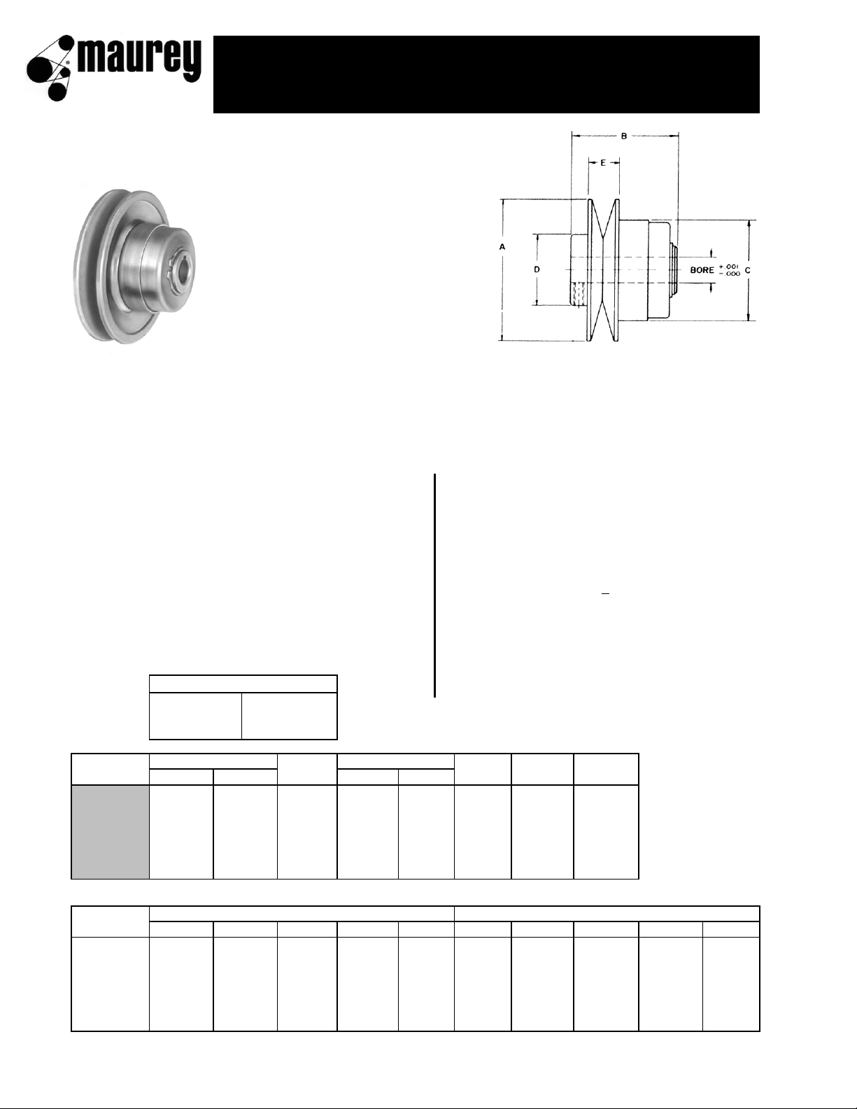
Spring-Loaded Sheaves - Automatic Type
Speed Ratios up to 2.19:1, available for drives of 1/4 to 2
H.P. Motor is equiped with Maurey spring-loaded sheave.
Spring-Loaded Sheaves - Manual Type Motor Bases
For fixed center drives.
G1
FEATURES:
1.
Single moving flange.
Simple trouble-free constr-
uction with a minimum of
working parts
2.
Grooved for Permawick
(cellulose fibre 85% lubri-
cating oil content) that holds
oil in suspension until such
time as needed on bushing
for lubrication.
3.
Nylon bushing between movable
flange and hub is continuously
lubricated by Permawick.
4.
Stainless steel key adds strength
and assures non-corrosion.
ORDERING PROCEDURE
ORDERING EXAMPLE FOR COMPLETE DRIVE
SPRING LOADED SHEAVE is driver sheave DRIVE REQUIREMENTS:
TO SELECT COMPANION SHEAVE, check chart of model no. 1/3 HP Motor @ 1750 RPM
selected. Refer to speed range desired. Adjacent column at right Motor Shaft Size: 5/8"
gives companion sheave number Driven Shaft Size: 1"
TO SELECT V-BELT to fit your drive move horizontally on same
Speed Range: 300 to 600 RPM
chart to desired center distance. Read down to obtain FHP
Belt Center Distance: 18" + 1/2"
V-belt number
REFER TO CHART, PAGE G-5
COMPANION SHEAVES DIMENSIONS - Section A. Select either 6325 or 6400 closest to requirement
MOTOR BASE DIMENSIONS - Page G-3 TO ORDER FROM CHART:
6400 x 5/8" Spring Loaded Sheave
AC110 x 1" Companion Sheave, Section A
4L600 V-Belt
5/8", 3/4", 7/8" 3/16" x 3/32" 6000 Standard Motor Base, Page G-3
1" 1/4" x 1/8"
Model
Speed
Belt
Drive
Weight
Number
1750
1160
Ratio
MIN
MAX
Section
Selection
Lbs
6325 1/3 1/4 1.65:1 1.91 3.15 A or B Page G-5 1.75
6400 1/2 1/3 2.00:1 1.95 3.90 A or B Page G-5 2.25
6500 1 & 3/4 1/2 2.05:1 2.37 4.84 B Page G-6 4.88
6600 1 3/4 2.19:1 2.67 5.84 B Page G-6 6.00
66150 1-1/2 1 2.19:1 2.67 5.84 B Page G-6 6.00
66200 2 1-1/2 2.19:1 2.67 5.84 B Page G-6 6.00
Model
DIMENSIONS (INCHES)
STOCK BORES (INCHES) MARKED "X"
Number
ABCDE
1/2
5/8
3/4
7/8
1
6325 3-1/4 2-3/8 2-5/16 1-5/8 11/16 X X X
6400 4 2-1/8 2-5/16 1-5/8 11/16 X X X
6500 5 3-5/8 3-3/16 1-7/8 15/16 X X X X
6600 6 3-7/8 3-3/16 1-7/8 15/16 X X X X
66150 6 3-7/8 3-3/16 1-7/8 15/16 X X X X
66200 6 3-7/8 3-3/16 1-7/8 15/16 X X X X
USE MAUREY MOTOR BASE NO. 6000, PAGE G-3
BORES AND KEYWAYS
1/2" None
spring loaded sheaves
for 4L "A'" and 5L "B" belts
G2
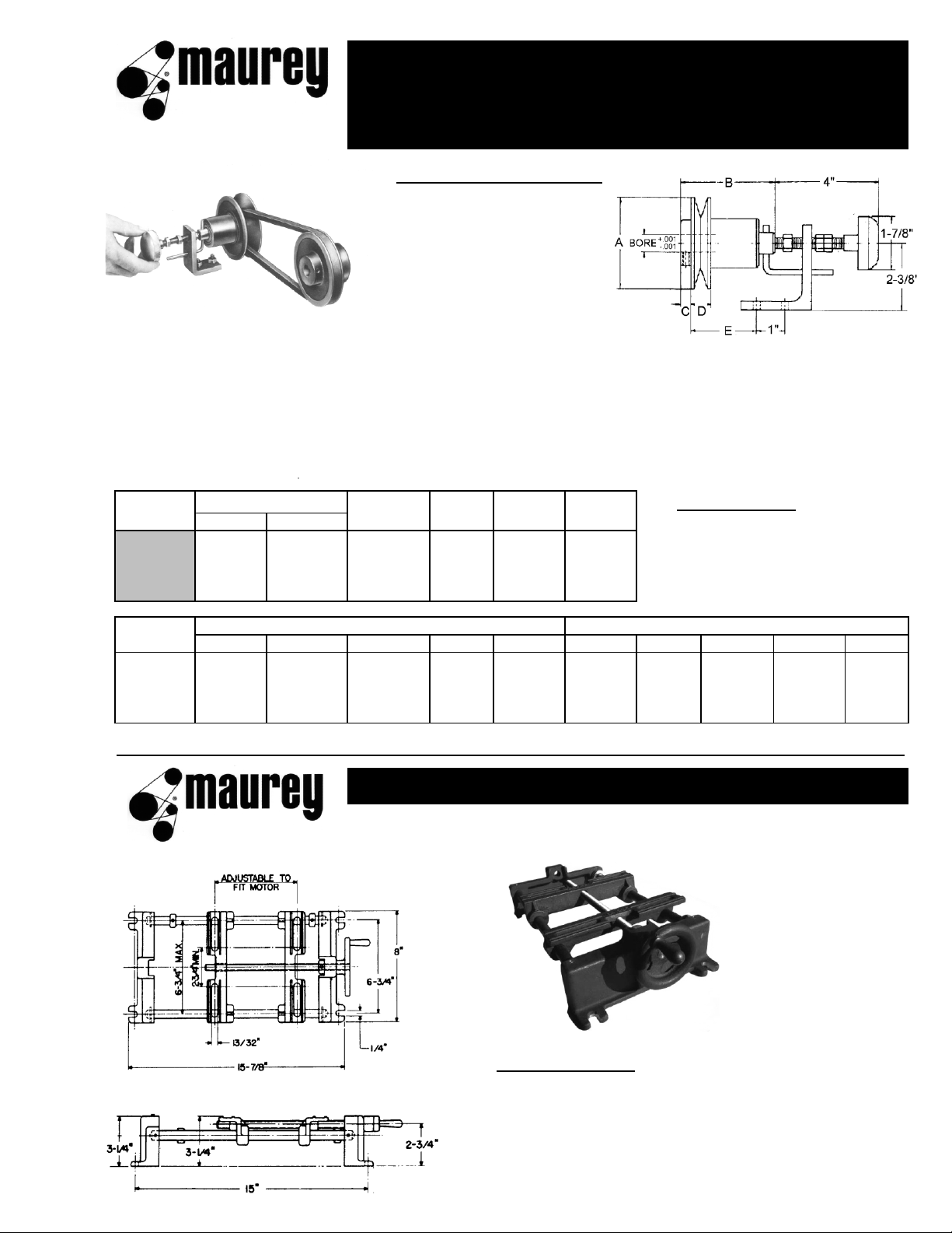
manual control sheaves and controls
for fixed center drives for 4L "A" and
5L "B" belts
MANUAL CONTROL SHEAVES
are used in conjunction with
spring-loaded sheaves to
maintain fixed center distance
and provide a higher speed
ratio than possible using only
a spring-loaded sheave and
movable motor base.
ORDERING PROCEDURE
TO SELECT A COMPOUND DRIVE, check the chart on page G-7 and select either your desired
horsepower and/or speed ratio. Adjacent column gives you specified model numbers, driven speeds
at desired RPM , and NEMA motor frame numbers
TO SELECT FHP V-BELT to fit your system, check charts on page G-7 and move horizontally from
deired compound drive to desired distance. Read down to obtain part number of V-Belt.
Model
Speed Belt Drive Weight
MC CONTROL
Number
1750
1160
Ratio
Section
Selection
Lbs
MUST BE ORDERED
6325M 1/3 & 1/4 1/4 2.72:1 A or B Page G-7 2.00
SEPARATELY
6400M 1/2 1/3 4.00:1 A or B Page G-7 2.25
6500M 1 & 3/4 1/2 4.17:1 A or B Page G-7 5.00
6600M 2, 1-1/2, 1 1-1/2, 1, 3/4 4.78:1 A or B Page G-7 6.50
Model
DIMENSIONS (INCHES)
STOCK BORES (INCHES) MARKED "X"
Number
ABCDE
1/2
5/8
3/4
7/8
1
6325M 3-1/4 3-11/32 3/8 11/16 3 X X X
6400M 4 3-11/32 3/8 11/16 3 X X X
6500M 5 4-5/16 1/2 15/16 4 X X X X
6600M 6 4-5/16 1/2 15/16 4 X X X X
For keyway dimensions please refer to chart on page G-2.
MODEL NO. 6000
Standard adjustable motor base for motors
up to and including 2 H.P. Easily moves the sheave
through its speed range. Shipping weight, 12 lbs.
adjustable motor bases
G3

Selection Procedure:
1.
Determine horsepower and/or speed ratio of your particular drive.
2.
Across to specified model number and your particular motor speed.
NEMA motor frames also indicated.
3.
Select proper motor base (NEMA motor frames also indicated).
4.
For complete drive details, turn to page that pertains to model number
specified in step 2. Page numbers located on bottom of chart.
Motor
Base
1750 RPM 1160 RPM Selection
6325 6325 6000
6325 6325 6000
6325 6325 6000
6400 6400 6000
6400 --- 6000
--- 6500 6000
6500 --- 6000
6600 --- 6000
--- 66150 6000
66150 --- 6000
--- 66200 6000
66200 --- 6000
DRIVE SELECTION FOR SPRING-LOADED SHEAVES
By: Horsepower and/or Speed Ratio
Speed Specified Model No.
Selection at Motor RPM
Selection
Horsepower Ratio
Selection
NEMA Motor Frames
1/4
1/3
1/2
1/2
3/4
3/4
1
1
1
1-1/2
1-1/2
2
1.65 : 1
1.65 : 1
1.65 : 1
2.00 : 1
2.00 : 1
2.05 : 1
2.05 : 1
2.19 : 1
2.19 : 1
2.19 : 1
48, 56, 56H, 66, 203, 204
48, 56, 56H, 66, 203, 204
56, 56H, 66, 203, 204, 182,
PAGE NUMBERS FOR ABOVE MODELS:
2.19 : 1
2.19 : 1
48, 56, 56H, 66
48, 56, 56H, 66
48, 56, 56H, 66, 203, 204
184, 143T, 145T
56, 56H, 66, 182, 184, 143T
145T, 224, 225, 203, 204
56, 56H, 66, 182, 184, 143T
145T, 203, 204
56, 56H, 66, 182, 184, 143T
145T, 203, 204, 224, 225
56, 56H, 66, 182, 184, 143T
145T, 203, 204, 224, 225
56, 56H, 66, 182, 184, 143T
145T, 224, 225
56, 56H, 66, 182, 184, 143T
145T, 224, 225
6325, 6400, 6500 ……………………………… PAGE G-2
6600, 66150, 66200 ……………………….…...PAGE G-2
G4

Companion
Sheave
Min. Max. Min. Max.
1045 1723 693 1142 AC33 7.9 8.9 9.9 11.9 13.9 14.9 16.9 18.9 19.9 21.9 23.9 24.9 29.9 34.9 39.9 44.9
983 1621 652 1075 AC35 7.8 8.8 9.8 11.8 13.8 14.8 16.8 18.8 19.8 21.8 23.8 24.8 29.8 34.8 39.8 44.8
857 1414 568 937 AC40 7.4 8.4 9.4 11.4 13.4 14.4 16.4 18.4 19.4 21.4 23.4 24.4 29.4 34.4 39.4 44.4
760 1253 504 830 AC45 7.0 8.0 9.0 11.0 13.0 14.0 16.0 18.0 19.0 21.0 23.0 24.0 29.0 34.0 39.0 44.0
682 1125 452 745 AC50 6.6 7.6 8.6 10.6 12.6 13.6 15.6 17.6 18.6 20.6 22.6 23.6 28.6 33.6 38.6 43.6
567 934 376 619 AC60 6.6 7.7 9.7 11.8 12.8 14.8 16.8 17.8 19.8 21.8 22.8 27.9 32.9 37.9 42.9
484 799 321 530 AC70 6.7 8.7 10.8 11.8 13.8 15.9 16.9 18.9 21.0 22.0 27.0 32.0 37.0 42.0
423 698 281 463 AC80 7.8 9.9 10.9 12.9 15.0 16.0 18.0 20.0 21.1 26.1 31.1 36.1 41.1
376 619 249 411 AC90 8.9 10.0 12.0 14.1 15.1 17.1 19.2 20.2 25.2 30.2 35.3 40.3
338 557 224 369 AC100 8.1 9.1 11.2 13.2 14.2 16.3 18.3 19.4 24.4 29.5 34.5 39.6
307 506 203 335 AC110 8.1 10.1 12.3 15.3 15.4 17.5 18.5 23.5 28.6 33.7 38.7
281 463 186 307 AC120 9.1 11.3 12.3 14.4 16.6 17.6 22.7 27.7 32.8 37.8
259 427 172 283 AC130 10.1 11.3 13.4 15.4 16.6 21.7 26.8 31.9 37.0
240 397 159 263 AC140 10.2 12.4 14.4 15.5 20.8 25.9 31.0 36.1
224 370 149 245 AC150 11.2 13.5 14.5 19.8 25.0 30.1 35.2
184 303 122 200 AC183 16.6 21.8 27.1 32.2
4L 4L 4L 4L 4L 4L 4L 4L 4L 4L 4L 4L
260 280 300 340 380 400 440 480 500 540 580 600
Companion
Sheave
Min. Max. Min. Max.
875 1750 580 1060 AC40 8.8 9.8 10.8 11.8 12.8 13.8 15.8 17.8 18.8 20.8 22.8 23.8 28.8 33.8 38.8 43.8
776 1552 514 1028 AC45 8.4 9.4 10.4 11.4 12.4 13.4 15.4 17.4 18.4 20.4 22.4 23.4 28.4 33.4 38.4 43.4
697 1394 462 924 AC50 8.0 9.0 10.0 11.0 12.0 13.0 15.0 17.0 18.0 20.0 22.0 23.0 28.0 33.0 38.0 43.0
632 1264 419 838 AC55 8.6 9.6 10.6 11.6 12.6 14.6 16.6 17.6 19.6 21.6 22.6 27.6 32.6 37.6 42.6
578 1156 383 766 AC60 8.1 9.1 10.2 11.2 12.2 14.2 16.2 17.2 19.2 21.2 22.2 27.2 32.2 37.2 42.2
533 1066 353 706 AC65 8.7 9.7 10.7 11.8 13.8 15.8 16.8 18.8 20.8 21.8 26.8 31.8 36.8 41.8
495 990 328 656 AC70 8.2 9.2 10.3 11.3 13.3 15.3 16.3 18.4 20.4 21.4 26.4 31.4 36.4 41.4
432 864 286 572 AC80 8.4 9.4 10.4 12.4 14.5 15.5 17.5 19.5 20.5 25.6 30.6 35.6 40.6
383 766 254 508 AC90 8.7 9.7 11.7 13.7 14.8 16.8 18.8 19.8 24.9 29.9 35.0 40.0
345 690 228 456 AC100 10.7 12.7 13.8 15.8 17.9 18.9 24.0 29.0 34.0 39.0
313 626 208 416 AC110 11.8 12.8 14.9 16.9 18.0 23.0 28.1 33.1 38.1
287 574 190 380 AC120 10.8 11.8 13.9 16.0 17.0 22.1 27.2 32.2 37.3
265 530 175 350 AC130 13.0 15.0 16.1 21.2 26.3 31.3 36.4
246 492 163 326 AC140 11.9 14.0 15.1 20.3 25.4 30.5 35.6
229 458 151 302 AC150 13.0 14.2 19.4 24.5 29.6 34.7
188 376 124 248 AC183 16.0 21.4 26.6 31.7
4L 4L 4L 4L 4L 4L 4L 4L 4L 4L 4L 4L
300 320 340 360 380 400 440 480 500 540 580 600
A68 A78 A88 A98
DRIVEN SPEED
CENTER DISTANCE (INCHES) AT MAXIMUM SPEED POSITION
1750 RPM 1160 RPM
MODEL NO. 6400 / SPEED AND CENTER DISTANCE TABLE
USE MOTOR BASE NO. 6000
A68 A78 A88 A98
DRIVEN SPEED
CENTER DISTANCE (INCHES) AT MAXIMUM SPEED POSITION
MODEL NO. 6325 / SPEED AND CENTER DISTANCE TABLE
USE MOTOR BASE NO. 6000
1160 RPM1750 RPM
G5

Companion
Sheave
Min. Max. Min. Max.
857 1750 568 1160 BC50 7.3 8.3 9.3 10.3 11.3 12.3 14.3 16.3 17.3 19.3 21.3 22.3 27.3 32.3 37.3 42.3
792 1616 525 1071 BC54 7.0 8.0 9.0 10.0 11.0 12.0 14.0 16.0 17.0 19.0 21.0 22.0 27.0 32.0 37.0 42.0
735 1502 487 995 BC58 7.7 8.7 9.7 10.7 11.7 13.7 15.7 16.7 18.7 20.7 21.7 26.7 31.7 36.7 41.7
710 1450 471 961 BC60 7.5 8.5 9.5 10.5 11.5 13.5 15.5 16.5 18.5 20.5 21.5 26.5 31.5 36.5 41.5
665 1357 441 900 BC64 7.2 8.2 9.2 10.2 11.2 13.2 15.2 16.2 18.2 20.2 21.2 26.2 31.2 36.2 41.2
625 1276 414 845 BC68 7.8 8.8 9.9 10.9 12.9 14.9 15.9 17.9 19.9 20.9 25.9 30.9 35.9 40.9
606 1238 402 821 BC70 7.6 8.6 9.6 10.7 12.7 14.7 15.7 17.7 19.7 20.7 25.7 30.7 35.7 40.7
589 1203 390 797 BC72 7.5 8.5 9.5 10.6 12.6 14.6 15.6 17.6 19.6 20.6 25.6 30.6 35.6 40.6
543 1109 360 735 BC78 7.9 9.0 10.0 12.0 14.0 15.0 17.0 19.0 20.0 25.1 30.1 35.1 40.1
469 958 311 635 BC90 8.3 9.3 11.3 13.3 14.3 16.4 18.4 19.4 24.4 29.5 34.5 39.5
430 879 285 582 BC98 10.2 12.2 13.2 15.2 17.3 18.3 23.3 28.4 33.4 38.4
369 754 246 500 BC114 10.9 11.9 14.0 16.0 17.0 22.1 27.1 32.2 37.2
328 670 217 444 BC128 10.5 12.5 14.6 15.6 19.8 25.9 31.0 36.0
300 612 199 406 BC140 11.5 13.6 14.7 19.8 24.9 30.0 35.0
265 542 176 359 BC158 11.7 12.7 18.1 23.2 28.3 33.4
223 454 147 301 BC188 15.0 20.3 25.6 30.7
Companion
Sheave
Min. Max. Min. Max.
800 1750 530 1160 BC60 8.7 9.7 10.7 11.7 12.7 13.7 14.7 15.7 16.7 17.7 19.7 20.7 25.7 30.7 35.7 40.7
774 1692 513 1122 BC62 8.6 9.6 10.6 11.6 12.6 13.6 14.6 15.6 16.6 17.6 19.6 20.6 25.6 30.6 35.6 40.6
749 1638 496 1086 BC64 8.4 9.4 10.4 11.4 12.4 13.4 14.4 15.4 16.4 17.4 19.4 20.4 25.4 30.4 35.4 40.4
726 1587 481 1052 BC66 8.3 9.3 10.3 11.3 12.3 13.3 14.3 15.3 16.3 17.3 19.3 20.3 25.3 30.3 35.3 40.3
704 1539 466 1020 BC68 8.1 9.1 10.1 11.1 12.1 13.1 14.1 15.1 16.1 17.1 19.1 20.1 25.1 30.1 35.1 40.1
683 1494 453 990 BC70 8.0 9.0 10.0 11.0 12.0 13.0 14.0 15.0 16.0 17.0 19.0 20.0 25.0 30.0 35.0 40.0
664 1452 440 962 BC72 8.8 9.8 10.8 11.8 12.8 13.8 14.8 15.8 16.8 18.8 19.8 24.8 29.8 34.8 39.8
612 1338 405 887 BC78 8.2 9.2 10.3 11.3 12.3 13.3 14.3 15.3 16.3 18.3 19.3 24.3 29.3 34.3 39.3
529 1156 350 766 BC90 9.3 10.3 11.3 12.3 13.3 14.3 15.4 17.4 18.4 23.4 28.4 33.4 38.4
485 1060 321 703 BC98 9.5 10.5 11.5 12.5 13.6 14.6 16.6 17.6 22.7 27.7 32.7 37.7
416 909 276 603 BC114 10.1 11.4 12.2 13.2 15.2 16.2 21.2 26.3 31.4 36.4
370 809 245 536 BC128 10.9 12.0 14.0 15.0 20.1 25.2 30.2 35.2
338 738 224 489 BC140 12.9 14.0 19.1 24.2 29.3 34.3
299 653 198 433 BC158 12.1 17.4 22.6 28.6 32.7
251 548 166 363 BC188 15.2 20.7 25.9 31.0
B49 B51 B55 B57
B55 B57
B33 B35 B37 B39 B41 B43 B48 B47
B41 B45 B47 B51
B67 B77 B87 B97
DRIVEN SPEED
CENTER DISTANCE (INCHES) AT MAXIMUM SPEED POSITION
1750 RPM 1160 RPM
MODEL NO. 6500 / SPEED AND CENTER DISTANCE TABLE
USE MOTOR BASE NO. 6000
MODEL NO. 6600, 66150, 66200 / SPEED AND CENTER DISTANCE TABLE
USE MOTOR BASE NO. 6000
B27 B29 B31 B33 B35 B37 B67 B77 B87 B97
1160 RPM1750 RPM
DRIVEN SPEED
CENTER DISTANCE (INCHES) AT MAXIMUM SPEED POSITION
G6

Manual control sheave can be used on driver or driven unit. In this example we will use manual control sheave on driver unit
Drive Requirements:
Desired:
Order:
1/3 H.P. Motor @ 1750 RPM Speed Range 875 to 3500 RPM Model 6400M x 5/8" Manual Control Sheave
Motor Shaft Size: 5/8" Belt Center Distance: 8.3" MC Control - Control for Manual Control Sheave
Driven Shaft Size: 5/8" Model 6400 x 5/8" Spring-Loaded Sheave
4L260 Belt
Min. Max. Min. Max.
1061
2886
703
1913
1061 2886 703 1913
580 2320
875 3500
568 2369
857 3574
530 2537
857 3574
800 3828
530 2537
800 3828
530 2537
800 3828
4L 4L 4L 4L 4L 4L 4L 4L 4L 4L 4L 4L 4L 4L 4L 4L
200 210 220 230 240 250 260 280 300 340 380 400 440 500 540 600
Compound Drive Selection Tables
Selection Selection 1750 RPM 1160 RPM
1750 RPM 1160 RPM NEMA Motor Frame Numbers
Model Number Selection
at Motor RPM
1/4
1/3
1/3
1/2
1/2
3/4
3/4
1-1/2
2
1
1
1
1-1/2
Compound
Drive
2.72 : 1
2.72 : 1
4.00 : 1
4.00 : 1
4.17 : 1
4.17 : 1
4.78 : 1
4.17 : 1
4.78 : 1
4.78 : 1
6500-6500M
6325-6325M
6325-6325M
6500-6500M
6500-6500M
6600-6600M
66150-6600M
6400-6400M
6325-6325M
6325-6325M
6400-6400M
6600-6600M
66150-6600M
CENTER DISTANCE (INCHES) FOR COMPOUND DRIVES
66100-6600M
66200-6600M
4.78 : 1
4.78 : 1
4.78 : 1 56, 56H, 66, 182, 184, 143T, 145T
56, 56H, 66, 182, 184, 143T, 145T
56, 56H, 66, 182, 184, 143T, 145T
56, 56H, 66, 182, 184, 143T, 145T
56, 56H, 66, 182, 184, 143T, 145T
Driven Speed
56, 56H, 66, 182, 184, 143T, 145T
48, 56, 56H, 66
56, 56H, 66, 182, 184, 143T, 145T
56, 56H, 66, 182, 184, 143T, 145T
56, 56H, 66, 182, 184, 143T, 145T
48, 56, 56H, 66
48, 56, 56H, 66
48, 56, 56H, 66
HP
Speed
Ratio
5.9 6.4 6.9
6325
6325M
6400
6400M
7.4 7.9 8.4 8.9 9.9 10.9 12.9 14.9 17.9 20.9
17.3
22.9
MANUAL CONTROL SHEAVE AT OPEN POSITION (MINIMUM P.D.)
SPRING LOADED SHEAVE AT CLOSED POSITION (MAXIMUM P.D.)
20.3 22.3 25.312.3 14.3 15.37.3 7.8
25.9
CENTER DISTANCE (INCHES) FOR COMPOUND DRIVES
Compound MANUAL CONTROL SHEAVE AT OPEN POSITION (MINIMUM P.D.)
6.2 6.7 8.3 9.3 10.3
15.9
Drive SPRING LOADED SHEAVE AT CLOSED POSITION (MAXIMUM P.D.)
6500
6.0 6.5 7.0 7.5 8.0 9.0 10.0 11.0 12.0 13.0 14.1 16.1 18.1 19.1 21.1 24.1
6500M
66150 6600
7.0 8.0 9.1 10.1 11.2 12.2
B51 B57
66200 6600M
B21 B22 B23 B24 B25 B27
20.3 23.313.2 15.3 17.3 18.3
ORDERING EXAMPLE FOR COMPLETE DRIVE PACKAGE
Selection Note: Most efficient drive occurs when manual control and spring-loaded sheave are same diameter.
B37 B41 B45 B47B29 B31 B33 B35
G7

G8
 Loading...