

Maurey Power Transmission TIMING BELT Catalog Supplement
Performance Advantages
Wide Range of Load Capacities
Alterations
Space Saving Design
Rebore Minimum Plain Bore
Add Keyway
Add Set Screw
Available For Belts 8mm and 14mm in Pitch
Engineered for Durability
Part Number Description
P 26 8M 20 JA
Requires JA Bushing
Width
Pitch
Number of Teeth
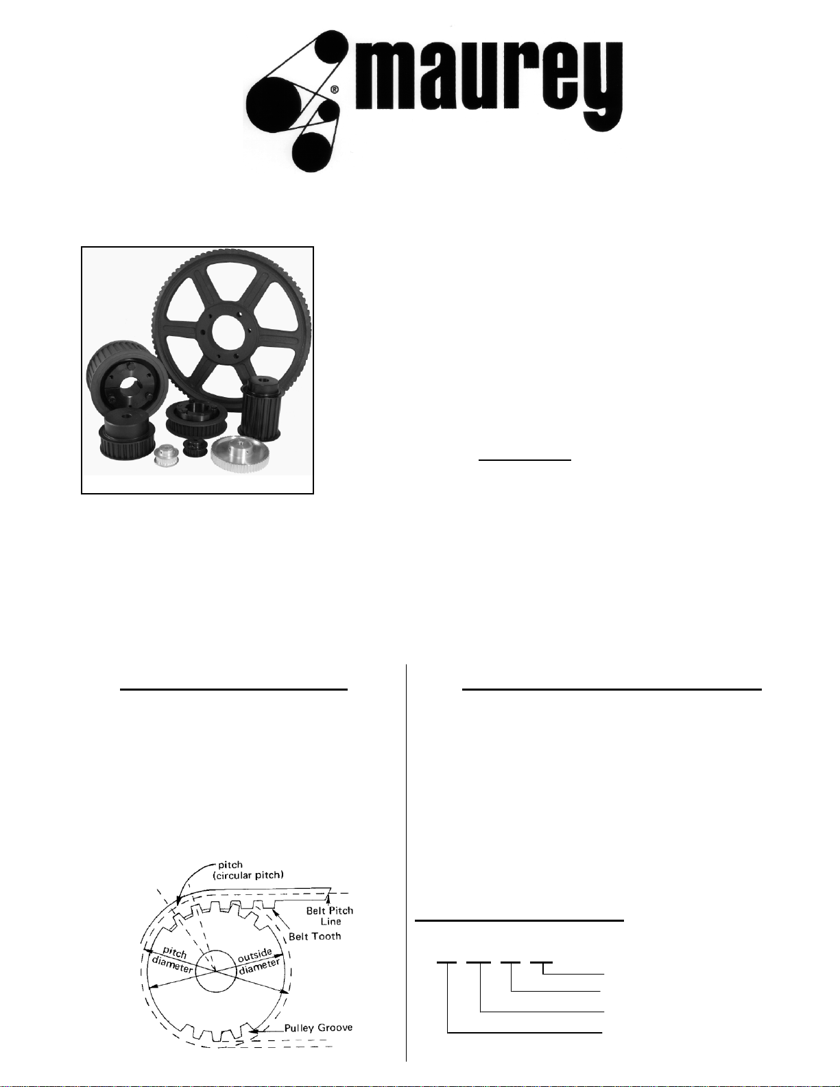
Maurey Positive Drive Pulleys are made in five
stock pitches to conform with the five stock
pitches of belts. They are available in a wide
range of stock widths and diameters. On the
belt, pitch is the distance between the tooth
centers on the pitch line of the belt. On the
pulley, pitch is the distance between groove
centers and is measured on the pulley pitch
circle.
Contact Maurey Customer Service for quantity breaks for alterations.
High Torque Sprocket Drives are designed to minimize
interference between the belt and sprocket during mesh,
providing greater horsepower without slippage or speed
variation. By designing belt teeth to disperse critical
stresses, belt performance is improved, assuring longer
belt life.
HIGH TORQUE DRIVE SPROCKETS POSITIVE DRIVE PULLEYS
TIMING BELT PULLEYS AND SPROCKETS
Maurey Timing Belt Drives provide a reliable, economical and troublefree alternative to transmit power and reduce drive weight and cost
when compared to chain drives and other types of belt drives.
Maurey Timing Belt Drives are designed for high capacity performance
exceeding the traditional limitations of chain and belt drives. The load
capacity varies from fractional horsepower to more than 600 H.P.
When compared to other belt
systems, Maurey Timing Belt
Drives permit a narrower drive,
reducing the cost of the drive by
cutting component costs.
Maurey will customize your Timing Belt component needs to suit the
application in which it is used. See list price book or consult factory for
various alteration charges.
E1
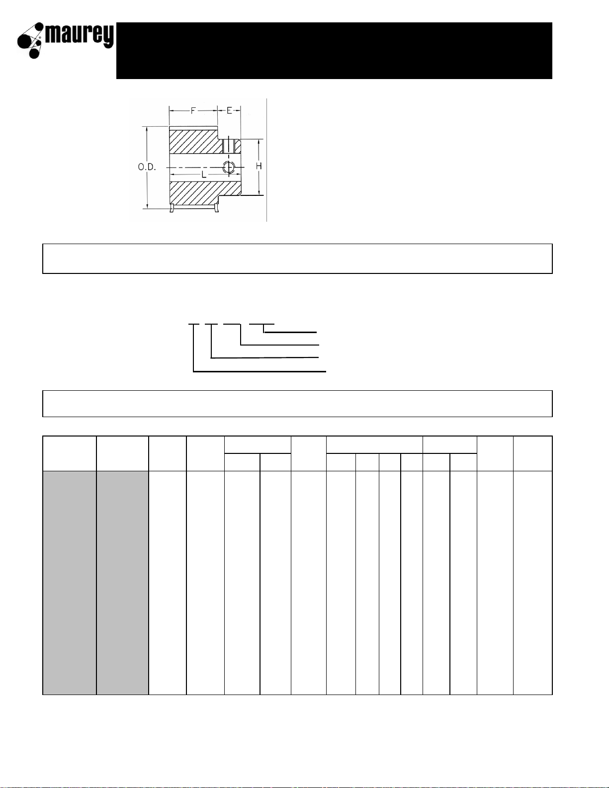
TYPE M
ALL "XL" PULLEYS ARE
DRILLED AND TAPPED.
TWO SET SCREWS ARE
INCLUDED NOT INSTALLED.
TYPE MF
Part Number Explanation
12 XL 037 - MPB
Minimum Plain Bore
Width
Pitch
Number of Grooves
Steel
Aluminum
Steel
Aluminum
Number
Pitch
Outside Diameter
Weight
Weight
Part
Part
of
Diameter
Type
Lbs
Lbs
Number
Number
Grooves
Pulley
Flange
ELHF Min
Max
(Approx.)
(Approx.)
10XL037MPB
10
.637
.617
29/32
M1F
7/32
25/32
7/16
9/16
3/16
1/4
.03
11XL037MPB 11 .700 .680 29/32 M1F 7/32 25/32 7/16 9/16 3/16 1/4 .03
12XL037MPB 12AXL037MPB 12 .764 .744 31/32 M1F 7/32 25/32 1/2 9/16 3/16 5/16 .06 .03
14XL037MPB 14AXL037MPB 14 .891 .871 1-7/64 M1F 7/32 25/32 9/16 9/16 1/4 3/8 .06 .05
15XL037MPB 15AXL037MPB 15 .955 .935 1-3/16 M1F 7/32 25/32 5/8 9/16 1/4 7/16 .09 .06
16XL037MPB 16AXL037MPB 16 1.019 .999 1-1/4 M1F 7/32 25/32 11/16 9/16 1/4 3/8 .09 .06
18XL037MPB 18AXL037MPB 18 1.146 1.126 1-3/8 M1F 7/32 25/32 13/16 9/16 1/4 9/16 .13 .09
20XL037MPB 20AXL037MPB 20 1.273 1.253 1-1/2 M1F 5/16 7/8 15/16 9/16 1/4 11/16 .19 .12
21XL037MPB 21AXL037MPB 21 1.377 1.317 1-9/16 M1F 5/16 7/8 15/16 9/16 1/4 11/16 .19 .12
22XL037MPB 22AXL037MPB 22 1.401 1.381 1-5/8 M1F 5/16 7/8 1 9/16 1/4 3/4 .22 .12
24XL037MPB 24AXL037MPB 24 1.528 1.508 1-3/4 M1F 5/16 7/8 1-1/16 9/16 1/4 13/16 .25 .15
28XL037MPB 28AXL037MPB 28 1.783 1.763 2 M1F 5/16 7/8 1-3/16 9/16 1/4 15/16 .34 .21
30XL037MPB 30AXL037MPB 30 1.910 1.890 2-1/8 M1F 5/16 7/8 1-3/8 9/16 5/16 1-1/16 .41 .22
32XL037MPB 32AXL037MPB 32 2.037 2.017 M1 7/16 1 1-1/2 9/16 5/16 1-3/16 .53 .25
36XL037MPB 36AXL037MPB 36 2.292 2.272 M1 7/16 1 1-1/2 9/16 5/16 1-3/16 .75 .30
40XL037MPB 40AXL037MPB 40 2.546 2.526 M1 7/16 1 1-1/2 9/16 5/16 1-3/16 .90 .31
42XL037MPB 42AXL037MPB 42 2.674 2.654 M2/M1* 7/16 1 1-5/8 9/16 5/16 1-3/16 1.06 .31
44XL037MPB 44AXL037MPB 44 2.801 2.781 M2/M1* 7/16 1 1-5/8 9/16 5/16 1-3/16 1.31 .31
48XL037MPB 48AXL037MPB 48 3.056 3.036 M2 7/16 1 1-5/8 9/16 5/16 1-3/16 1.50 .38
60XL037MPB 60AXL037MPB 60 3.820 3.800 M2 7/16 1 1-5/8 9/16 3/8 1-3/16 1.40 .38
72XL037MPB 72AXL037MPB 72 4.584 4.564 M2 7/16 1 1-5/8 9/16 3/8 1-3/16 1.75 .50
t
Minimum plain bore only carried in stock
Maximum bore possible without keyseat
* Aluminum in this size is M1 style
1/5" pitch (XL) stock pulley dimensions
positive drive pulleys
Bore Range
Dimensions, Inches
Pulleys stocked in 3/8 inch (XL037) width only. For belts 1/4 inch (XL025),
5/16 inch (XL031), and 3/8 inch (XL037) wide.
Figure Following Letter in Column Headed "TYPE" in Table Below Indicates Sheave Construction
1 - Solid, No Web. 2 - Web. 3 - Arms "F" Indicates Flanged Pulley
E2
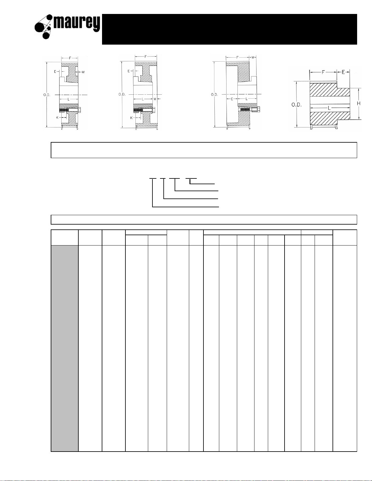
TYPE C TYPE D TYPE E TYPE M
TYPE CF TYPE DF TYPE EF TYPE MF
Part Number Explanation
18 L 050 - QD
Requires QD Bushing
Width
Pitch
Number of Grooves
Part
Number
Pitch
Outside Diameter
Weight
Number
of
Diameter
Bush
Type*
Lbs
Grooves
Pulley
Flange
ELMKHFMin
Max
(Approx.)
10L050MPB
10
1.194
1.164
1-7/16
*
M1F
3/8
1-1/8
13/16
3/4
3/8
9/16
.28
12L050MPB 12 1.432 1.402 1-11/16 * M1F 1/2 1-1/4 1-1/16 3/4 3/8 13/16 .30
13L050MPB 13 1.552 1.522 1-3/4 * M1F 1/2 1-1/4 1-1/8 3/4 3/8 13/16 .35
14L050MPB 14 1.671 1.641 1-15/16 * M1F 5/8 1-1/4 1-1/8 3/4 3/8 7/8 .40
15L050MPB 15 1.790 1.760 1-15/16 * M1F 1/2 1-1/4 1-1/8 3/4 1/2 15/16 .50
16L050MPB 16 1.910 1.880 2-3/16 * M1F 5/8 1-3/8 1-7/16 3/4 1/2 1-1/8 .60
17L050MPB 17 2.029 1.999 2-3/16 * M1F 5/8 1-3/8 1-7/16 3/4 1/2 1-1/8 .65
18L050MPB 18 2.149 2.119 2-3/8 * M1F 5/8 1-3/8 1-9/16 3/4 1/2 1-3/16 .75
18L050QD 18 2.149 2.119 2-3/8 JA E1F 3/16 1 7/16 3/4 1/2 1-3/16 .40
19L050MPB 19 2.268 2.238 2-3/8 * M1F 5/8 1-3/8 1-5/8 3/4 1/2 1-3/16 .80
20L050MPB 20 2.837 2.357 2-5/8 * M1F 5/8 1-3/8 1-11/16 3/4 1/2 1-1/4 .94
20L050QD 20 2.837 2.357 2-5/8 JA E1F 3/16 1 7/16 3/4 1/2 1-3/16 .50
21L050MPB 21 2.507 2.477 2-3/4 * M1F 11/16 1-7/16 1-7/8 3/4 1/2 1-5/16 1.0
22L050MPB 22 2.626 2.596 3 * M1F 3/4 1-1/2 2 3/4 1/2 1-1/2 1.1
22L050QD 22 2.626 2.596 3 JA E1F 3/16 1 7/16 3/4 1/2 1-3/16 .70
24L050MPB 24 2.865 2.835 3-1/4 * M1F 3/4 1-1/2 2-1/4 3/4 1/2 1-5/8 1.6
24L050QD 24 2.865 2.835 3-1/4 SH E1F 0 1-1/4 1/2 3/4 1/2 1-5/8 .70
26L050MPB 26 3.104 3.074 3-5/16 * M1F 3/4 1-1/2 2-1/4 3/4 1/2 1-5/8 2.3
26L050QD 26 3.104 3.074 3-5/16 SH C1F 1/2 1-1/4 0 0 3/4 1/2 1-5/8 1.0
28L050MPB 28 3.342 3.312 3-9/16 * M1F 3/4 1-1/2 2-1/4 3/4 1/2 1-5/8 2.5
28L050QD 28 3.342 3.312 3-9/16 SH C1F 1/2 1-1/4 0 0 3/4 1/2 1-5/8 1.1
30L050MPB 30 3.581 3.551 3-3/4 * M1F 3/4 1-1/2 2-1/4 3/4 1/2 1-5/8 2.7
30L050QD 30 3.581 3.551 3-3/4 SDS C1F 9/16 1-5/16 0 0 3/4 1/2 1-15/16 1.1
32L050MPB 32 3.820 3.790 4 * M1F 7/8 1-5/8 2-9/16 3/4 1/2 1-7/8 3.0
32L050QD 32 3.820 3.790 4 SDS C1F 9/16 1-5/16 0 0 3/4 1/2 1-15/16 1.4
36L050QD 36 4.297 4.267 4-17/32 SDS C1F 9/16 1-5/16 0 0 3/4 1/2 1-15/16 2.0
40L050QD 40 4.775 4.745 5 SDS D1F 9/16 1-5/16 0 0 3/4 1/2 1-15/16 2.8
44L050QD 44 5.252 5.222 5-31/64 SDS C1F 9/16 1-5/16 0 0 3/4 1/2 1-15/16 3.6
48L050QD 48 5.730 5.700 6 SDS D1F 9/16 1-5/16 0 0 3/4 1/2 1-15/16 4.4
60L050QD 60 7.162 7.132 SD C3 13/16 1-13/16 1/4 +1/4 3/4 1/2 1-15/16 4.2
72L050QD 72 8.594 8.564 SD C3 13/16 1-13/16 1/4 +1/4 3/4 1/2 1-15/16 6.6
84L050QD 84 10.027 9.997 SD C3 13/16 1-13/16 1/4 +1/4 3/4 1/2 1-15/16 5.8
96L050QD 96 11.459 11.429 SD C3 13/16 1-13/16 1/4 +1/4 3/4 1/2 1-15/16 7.4
120L050QD 120 14.324 14.294 SD C3 13/16 1-13/16 1/4 +1/4 3/4 1/2 1-15/16 10.0
Weight shown is for pulley without bushing
*Bored to suit construction (Type M) minimum plain bore only carried in stock
3/8" pitch (L) stock pulley dimensions
positive drive pulleys
hMaximum bore without keyway
Bore Range
Dimensions, Inches
FOR BELTS 1/2 INCH WIDE h 3/8 INCH PITCH (L050)
Figure Following Letter in Column Headed "TYPE" in Table Below Indicates Sheave Construction
1 - Solid, No Web. 2 - Web. 3 - Arms "F" Indicates Flanged Pulley
E3
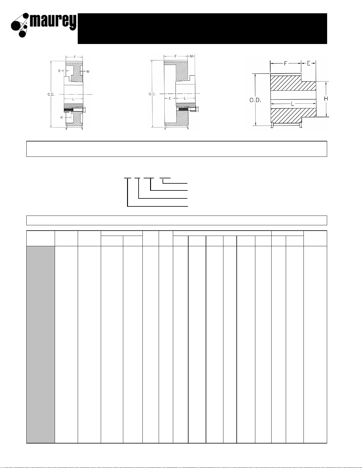
TYPE C TYPE E TYPE M
TYPE CF TYPE EF TYPE MF
Part Number Explanation
18 L 075 - QD
Requires QD Bushing
Width
Pitch
Number of Grooves
Part
Number
Pitch
Outside Diameter
Weight
Number
of
Diameter
Bush
Type
Lbs
Grooves
Pulley
Flange
ELMKHFMin
Max
(Approx.)
12L075MPB
12
1.432
1.402
1-11/16
*
M1F
1/2
1-1/2
1-1/16
1
3/8
13/16
.4
13L075MPB 13 1.522 1.552 1-11/16 * M1F 1/2 1-1/2 1-1/8 1 3/8 13/16 .4
14L075MPB 14 1.671 1.641 1-15/16 * M1F 1/2 1-1/2 1-1/8 1 3/8 7/8 .5
15L075MPB 15 1.790 1.760 1-15/16 * M1F 1/2 1-1/2 1-1/8 1 1/2 7/8 .6
16L075MPB 16 1.910 1.880 2-3/16 * M1F 5/8 1-5/8 1-7/16 1 1/2 1-1/8 .7
17L075MPB 17 2.029 1.999 2-3/16 * M1F 1/2 1-1/2 1-7/16 1 1/2 1-1/8 .8
18L075MPB 18 2.149 2.119 2-3/8 * M1F 5/8 1-5/8 1-9/16 1 1/2 1-3/16 .9
18L075QD 18 2.149 2.119 2-3/8 JAr E1F 7/16 1 7/16 1 1/2 1-3/16 .5
19L075MPB 19 2.268 2.238 2-3/8 * M1F 5/8 1-5/8 1-5/8 1 1/2 1-3/16 1.1
20L075MPB 20 2.387 2.357 2-5/8 * M1F 5/8 1-5/8 1-11/16 1 1/2 1-1/4 1.5
20L075QD 20 2.387 2.357 2-5/8 JAr E1F 7/16 1 7/16 1 1/2 1-3/16 .7
21L075MPB 21 2.507 2.477 2-3/4 * M1F 5/8 1-5/8 1-7/8 1 1/2 1-5/16 1.6
22L075MPB 22 2.626 2.596 3 * M1F 3/4 1-3/4 2 1 1/2 1-1/2 1.8
22L075QD 22 2.626 2.596 3 JAr E1F 7/16 1 7/16 1 1/2 1-3/16 .8
24L075MPB 24 2.865 2.835 3-1/4 * M1F 3/4 1-3/4 2-1/4 1 5/8 1-5/8 2.1
24L075QD 24 2.865 2.835 3-1/4 SH E1F 3/16 1-1/4 1/2 1 1/2 1-5/8 .8
26L075MPB 26 3.104 3.074 3-5/16 * M1F 3/4 1-3/4 2-1/4 1 5/8 1-5/8 2.8
26L075QD 26 3.104 3.074 3-5/16 SH E1F 3/16 1-1/4 1/2 1 1/2 1-5/8 1.1
28L075MPB 28 3.342 3.312 3-9/16 * M1F 3/4 1-3/4 2-1/4 1 5/8 1-5/8 3.1
28L075QD 28 3.342 3.312 3-9/16 SH E1F 3/16 1-1/4 1/2 1 1/2 1-5/8 1.3
30L075MPB 30 3.581 3.551 3-3/4 * M1F 3/4 1-3/4 2-1/4 1 5/8 1-5/8 3.4
30L075QD 30 3.581 3.551 3-3/4 SDS E1F 1/4 1-5/16 9/16 1 1/2 1-15/16 1.5
32L075MPB 32 3.820 3.790 4 * M1F 7/8 1-7/8 2-9/16 1 5/8 1-7/8 3.7
32L075QD 32 3.820 3.790 4 SDS E1F 1/4 1-5/16 9/16 1 1/2 1-15/16 1.7
36L075QD 36 4.297 4.267 4-17/32 SDS C1F 5/16 1-5/16 0 1/4 1 1/2 1-15/16 2.3
40L075QD 40 4.775 4.745 5 SDS C1F 5/16 1-5/16 0 1/4 1 1/2 1-15/16 3.1
44L075QD 44 5.252 5.222 5-31/64 SDS C1F 5/16 1-5/16 0 1/4 1 1/2 1-15/16 4.0
48L075QD 48 5.730 5.700 6 SDS C1F 5/16 1-5/16 0 1/4 1 1/2 1-15/16 4.6
60L075QD 60 7.162 7.132 SD C3 11/16 1-13/16 1/8 +1/8 1 1/2 1-15/16 4.7
72L075QD 72 8.594 8.564 SD C3 11/16 1-13/16 1/8 +1/8 1 1/2 1-15/16 6.5
84L075QD 84 10.027 9.997 SD C3 11/16 1-13/16 1/8 +1/8 1 1/2 1-15/16 6.3
96L075QD 96 11.459 11.429 SD C3 11/16 1-13/16 1/8 +1/8 1 1/2 1-15/16 9.4
120L075QD 120 14.324 14.294 SD C3 11/16 1-13/16 1/8 +1/8 1 1/2 1-15/16 13.8
*Bored to suit construction (Type M) minimum plain bore only carried in stock Weight shown is for pulley without bushing
"r" = Reverse mount only hMaximum bore without keyway
3/8" pitch (L) stock pulley dimensions
positive drive pulleys
Dimensions, Inches
Bore Range
FOR BELTS 3/4 INCH WIDE h 3/8 INCH PITCH (L075)
Figure Following Letter in Column Headed "TYPE" in Table Below Indicates Sheave Construction
1 - Solid, No Web. 2 - Web. 3 - Arms "F" Indicates Flanged Pulley
E4

TYPE C TYPE E TYPE M
TYPE CF TYPE EF TYPE MF
Part Number Explanation
18 L 100 - QD
Requires QD Bushing
Width
Pitch
Number of Grooves
Part
Number
Pitch
Outside Diameter
Weight
Number
of
Diameter
Bush
Type
Lbs
Grooves
Pulley
Flange
ELMKHFMin
Max
(Approx.)
13L100MPB
13
1.552
1.522
1-3/4*M1F
1/2
1-3/4
1-1/8
1-1/4
3/8
7/8
.5
14L100MPB 14 1.671 1.641 1-15/16 * M1F 1/2 1-3/4 1-1/8 1-1/4 3/8 7/8 .6
15L100MPB 15 1.790 1.760 1-15/16 * M1F 1/2 1-3/4 1-1/8 1-1/4 1/2 7/8 .7
16L100MPB 16 1.910 1.880 2-3/16 * M1F 5/8 1-7/8 1-7/16 1-1/4 1/2 1-1/8 .8
17L100MPB 17 2.029 1.999 2-3/16 * M1F 1/2 1-3/4 1-7/16 1-1/4 1/2 1-1/8 1.0
18L100MPB 18 2.149 2.119 2-3/8 * M1F 5/8 1-7/8 1-5/8 1-1/4 1/2 1-3/16 1.1
18L100QD 18 2.149 2.119 2-3/8 JAr E1F 11/16 1 7/16 1-1/4 1/2 1-3/16 .7
19L100MPB 19 2.268 2.238 2-3/8 * M1F 5/8 1-7/8 1-3/4 1-1/4 1/2 1-3/16 1.4
20L100MPB 20 2.387 2.357 2-5/8 * M1F 5/8 1-7/8 1-11/16 1-1/4 1/2 1-1/4 1.75
20L100QD 20 2.387 2.357 2-5/8 JAr E1F 11/16 1 7/16 1-1/4 1/2 1-3/16 .9
21L100MPB 21 2.507 2.477 2-3/4 * M1F 5/8 1-7/8 1-7/8 1-1/4 5/8 1-5/16 1.8
22L100MPB 22 2.626 2.596 3 * M1F 3/4 2 2 1-1/4 5/8 1-1/2 2.0
22L100QD 22 2.626 2.596 3 JAr E1F 11/16 1 7/16 1-1/4 1/2 1-3/16 1.0
24L100MPB 24 2.865 2.835 3-1/4 * M1F 3/4 2 2-1/4 1-1/4 5/8 1-5/8 2.5
24L100QD 24 2.865 2.835 3-1/4 SH E1F 7/16 1-1/4 1/2 1-1/4 1/2 1-5/8 1.0
26L100MPB 26 3.104 3.074 3-5/16 * M1F 7/8 2-1/8 2-1/2 1-1/4 5/8 1-7/8 3.3
26L100QD 26 3.104 3.074 3-5/16 SH E1F 7/16 1-1/4 1/2 1-1/4 1/2 1-5/8 1.3
28L100MPB 28 3.342 3.312 3-9/16 * M1F 1 2-1/4 2-1/2 1-1/4 5/8 2 3.6
28L100QD 28 3.342 3.312 3-9/16 SH E1F 7/16 1-1/4 1/2 1-1/4 1/2 1-5/8 1.7
30L100MPB 30 3.581 3.551 3-3/4 * M1F 1 2-1/4 2-15/16 1-1/4 5/8 2-1/8 4.0
30L100QD 30 3.581 3.551 3-3/4 SDS E1F 1/2 1-5/16 9/16 1-1/4 1/2 1-15/16 2.0
32L100MPB 32 3.820 3.790 4 * M1F 1 2-1/4 3-1/8 1-1/4 5/8 1-7/8 4.4
32L100QD 32 3.820 3.790 4 SDS E1F 1/2 1-5/16 9/16 1-1/4 1/2 1-15/16 2.1
36L100QD 36 4.297 4.267 4-17/32 SDS C1F 5/16 1-5/16 0 1/2 1-1/4 1/2 1-15/16 2.6
40L100QD 40 4.775 4.745 5 SDS C1F 1/16 1-5/16 0 1/2 1-1/4 1/2 1-15/16 3.4
44L100QD 44 5.252 5.222 5-31/64 SDS C1F 1/16 1-5/16 0 1/2 1-1/4 1/2 1-15/16 4.2
48L100QD 48 5.730 5.700 6 SDS C1F 1/16 1-5/16 0 1/2 1-1/4 1/2 1-15/16 5.1
60L100QD 60 7.162 7.132 SD C3 9/16 1-13/16 0 0 1-1/4 1/2 1-15/16 6.0
72L100QD 72 8.594 8.564 SD C3 9/16 1-13/16 0 0 1-1/4 1/2 1-15/16 7.5
84L100QD 84 10.027 9.997 SD C3 9/16 1-13/16 0 0 1-1/4 1/2 1-15/16 6.9
96L100QD 96 11.459 11.429 SD C3 9/16 1-13/16 0 0 1-1/4 1/2 1-15/16 11.2
120L100QD 120 14.324 14.294 SD C3 9/16 1-13/16 0 0 1-1/4 1/2 1-15/16 16.0
*Bored to suit construction (Type M) minimum plain bore only carried in stock Weight shown is for pulley without bushing
"r" = Reverse mount only h
Maximum bore without keyway
3/8" pitch (L) stock pulley dimensions
positive drive pulleys
Dimensions, Inches
Bore Range
FOR BELTS 1 INCH WIDE h 3/8 INCH PITCH (L100)
Figure Following Letter in Column Headed "TYPE" in Table Below Indicates Sheave Construction
1 - Solid, No Web. 2 - Web. 3 - Arms "F" Indicates Flanged Pulley
E5
 Loading...