

FEATURES:
1.
Single moving flange.
Simple trouble-free constr-
uction with a minimum of
working parts
2.
Grooved for Permawick
(cellulose fibre 85% lubri-
cating oil content) that holds
oil in suspension until such
time as needed on bushing
for lubrication.
3.
Nylon bushing between movable
flange and hub is continuously
lubricated by Permawick.
4.
Stainless steel key adds strength
and assures non-corrosion.
ORDERING PROCEDURE
ORDERING EXAMPLE FOR COMPLETE DRIVE
SPRING LOADED SHEAVE is driver sheave DRIVE REQUIREMENTS:
TO SELECT COMPANION SHEAVE, check chart of model no. 1/3 HP Motor @ 1750 RPM
selected. Refer to speed range desired. Adjacent column at right Motor Shaft Size: 5/8"
gives companion sheave number Driven Shaft Size: 1"
TO SELECT V-BELT to fit your drive move horizontally on same
Speed Range: 300 to 600 RPM
chart to desired center distance. Read down to obtain FHP
Belt Center Distance: 18" + 1/2"
V-belt number
REFER TO CHART, PAGE G-5
COMPANION SHEAVES DIMENSIONS - Section A. Select either 6325 or 6400 closest to requirement
MOTOR BASE DIMENSIONS - Page G-3 TO ORDER FROM CHART:
6400 x 5/8" Spring Loaded Sheave
AC110 x 1" Companion Sheave, Section A
4L600 V-Belt
5/8", 3/4", 7/8" 3/16" x 3/32" 6000 Standard Motor Base, Page G-3
1" 1/4" x 1/8"
Model
Speed
Belt
Drive
Weight
Number
1750
1160
Ratio
MIN
MAX
Section
Selection
Lbs
6325 1/3 1/4 1.65:1 1.91 3.15 A or B Page G-5 1.75
6400 1/2 1/3 2.00:1 1.95 3.90 A or B Page G-5 2.25
6500 1 & 3/4 1/2 2.05:1 2.37 4.84 B Page G-6 4.88
6600 1 3/4 2.19:1 2.67 5.84 B Page G-6 6.00
66150 1-1/2 1 2.19:1 2.67 5.84 B Page G-6 6.00
66200 2 1-1/2 2.19:1 2.67 5.84 B Page G-6 6.00
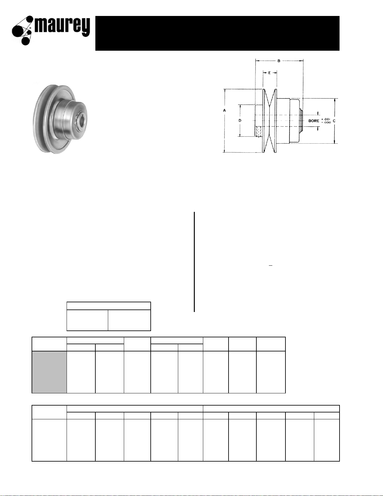
Model
DIMENSIONS (INCHES)
STOCK BORES (INCHES) MARKED "X"
Number
ABCDE
1/2
5/8
3/4
7/8
1
6325 3-1/4 2-3/8 2-5/16 1-5/8 11/16 X X X
6400 4 2-1/8 2-5/16 1-5/8 11/16 X X X
6500 5 3-5/8 3-3/16 1-7/8 15/16 X X X X
6600 6 3-7/8 3-3/16 1-7/8 15/16 X X X X
66150 6 3-7/8 3-3/16 1-7/8 15/16 X X X X
66200 6 3-7/8 3-3/16 1-7/8 15/16 X X X X
USE MAUREY MOTOR BASE NO. 6000, PAGE G-3
BORES AND KEYWAYS
1/2" None
spring loaded sheaves
for 4L "A'" and 5L "B" belts
G2
manual control sheaves and controls
for fixed center drives for 4L "A" and
5L "B" belts
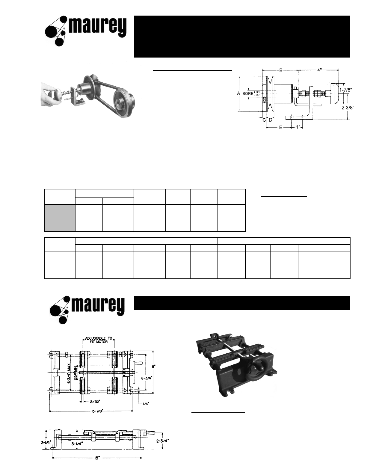
MANUAL CONTROL SHEAVES
are used in conjunction with
spring-loaded sheaves to
maintain fixed center distance
and provide a higher speed
ratio than possible using only
a spring-loaded sheave and
movable motor base.
ORDERING PROCEDURE
TO SELECT A COMPOUND DRIVE, check the chart on page G-7 and select either your desired
horsepower and/or speed ratio. Adjacent column gives you specified model numbers, driven speeds
at desired RPM , and NEMA motor frame numbers
TO SELECT FHP V-BELT to fit your system, check charts on page G-7 and move horizontally from
deired compound drive to desired distance. Read down to obtain part number of V-Belt.
Model
Speed Belt Drive Weight
MC CONTROL
Number
1750
1160
Ratio
Section
Selection
Lbs
MUST BE ORDERED
6325M 1/3 & 1/4 1/4 2.72:1 A or B Page G-7 2.00
SEPARATELY
6400M 1/2 1/3 4.00:1 A or B Page G-7 2.25
6500M 1 & 3/4 1/2 4.17:1 A or B Page G-7 5.00
6600M 2, 1-1/2, 1 1-1/2, 1, 3/4 4.78:1 A or B Page G-7 6.50
Model
DIMENSIONS (INCHES)
STOCK BORES (INCHES) MARKED "X"
Number
ABCDE
1/2
5/8
3/4
7/8
1
6325M 3-1/4 3-11/32 3/8 11/16 3 X X X
6400M 4 3-11/32 3/8 11/16 3 X X X
6500M 5 4-5/16 1/2 15/16 4 X X X X
6600M 6 4-5/16 1/2 15/16 4 X X X X
For keyway dimensions please refer to chart on page G-2.
MODEL NO. 6000
Standard adjustable motor base for motors
up to and including 2 H.P. Easily moves the sheave
through its speed range. Shipping weight, 12 lbs.
adjustable motor bases
G3
 Loading...