

Maurey Power Transmission FUL-GRIP Catalog Supplement
MULTI-V FUL-GRIP SHEAVES AND BUSHINGS
FUL-GRIP (QD
) BUSHINGS
FUL-GRIP (QD) SHEAVES
STANDARD MULTI-V SHEAVES
SPECIAL MADE-TO-ORDER SHEAVES
Industry puts Maurey sheaves on more drives every year simply because it pays to do so.
Machined from close-grained, grey iron castings and statically balanced to MPTA standards,
these sheaves will stand up to hard service and provide smooth, quiet-running, belt-saving
performance. However, please note that cast iron sheaves cannot exceed 6500 feet per a
minute rim speed. Also, special or dynamic balancing should be considered when rim
speeds exceed 5000 feet per a minute. Maurey sheaves are available in stock sizes for B, C,
D section belts. Maurey also offers special made-to-order items for B, C, D section belts as
well. The Ful-Grip bushing system is Maurey's answer to the need for sheaves that are
installed, removed, and interchanged with the ultimate in ease and speed. With tapered bores
to slip easily over flanged and detachable bushings, tapered to match the rims, Ful-Grips are
the adaptablility champions. Installation instructions in this section show how easily FulGrips make it possible to retain the bushing and change the sheave to suit speed,or retain the
sheave and change the bushing to fit a different shaft size.
C1
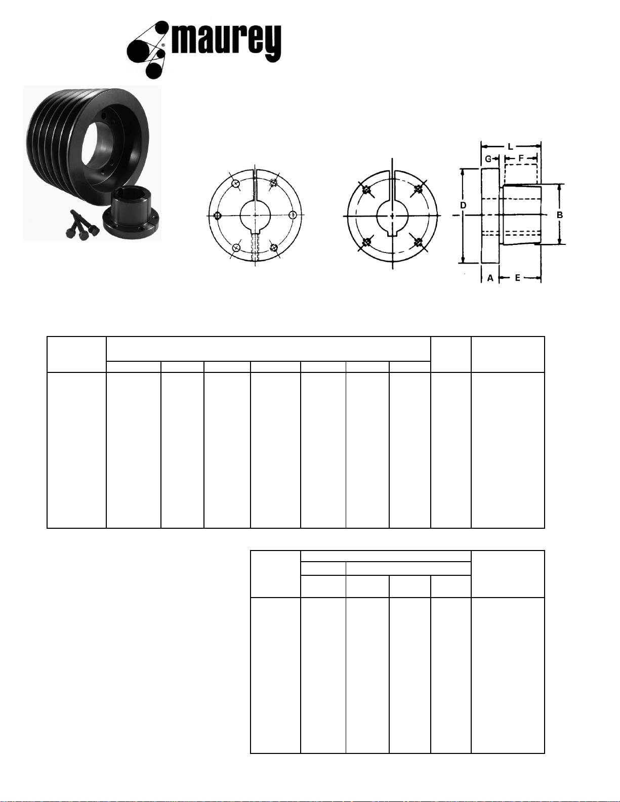
ful-grip bushing data
Bushings JA to J Inclusive Bushings M to S inclusive
NOTE: JA & SH bushings have no set screw over keyseat
FUL-GRIP BUSHING DIMENSIONS
Bolt
Cap
Bushing Dimensions in Inches
Circle Screws
ABDEFGL
Required
JA
5/16 1.375 2 11/16 5/8 1/8 1 1-21/32 3 - #10 x 1
SH
3/8 1.871 2-11/16 7/8 13/16 1/8 1-1/4 2-1/4 3 - 1/4 x 1-3/8
SDS
7/16 2.1875 3-3/16 7/8 3/4 1/8 1-5/16 2-11/16 3 - 1/4 x 1-3/8
SD
7/16 2.1875 3-3/16 1-3/8 1-1/4 1/8 1-13/16 2-11/16 3 - 1/4 x 2
SK
1/2 2.8125 3-7/8 1-3/8 1-1/4 1/8 1-7/8 3-5/16 3 - 5/16 x 2
SF
1/2 3.125 4-5/8 1-1/2 1-1/4 1/8 2 3-7/8 3 - 3/8 x 2
E
3/4 3.834 6 1-7/8 1-5/8 1/8 2-5/8 5 3 - 1/2 x 2-3/4
F
13/16 4.4375 6-5/8 2-13/16 2-1/2 3/16 3-5/8 5-5/8 3 - 9/16 x 3-1/2
J
1 5.1484 7-1/4 3-1/2 3-3/16 3/16 4-1/2 6-1/4 3 - 5/8 x 4-1/2
M
1-1/4 6.500 9 5-1/2 5-3/16 3/16 6-3/4 7-7/8 4 - 3/4 x 6-3/4
N
1-1/2 7.000 10 6-5/8 6-1/4 1/4 8-1/8 8-1/2 4 - 7/8 x 8
P
1-3/4 8.250 11-3/4 7-5/8 7-1/4 1/4 9-3/8 10 4 - 1 x 9-1/2
Stock Bore Range
Bushing
Minimum Weight
Certain bores in "Ful-Grip"
Standard
Standard
Shallow
No
Lbs.
bushings are of such a size
Keyseat
Keyseat
Keyseat
Keyseat
that standard depth keyseats
JA
1/2 1 1-3/16 1-1/4 .8
cannot be furnished. When
SH
1/2 1-3/8 1-5/8 1-11/16 1.0
a shallow keyseat is required,
SDS
1/2 1-11/16 1-15/16 2 1.2
a rectangular key of the proper
SD
1/2 1-11/16 1-15/16 2 1.5
dimension is furnished with
SK
1/2 2-1/8 2-1/2 2-5/8 2.0
the bushing. The table to the
right lists some keyseat
SF
1/2 2-1/4 2-3/4 2-15/16 3.5
specifications for all bushing
E
7/8 2-3/4 3-7/16 3-1/2 9.0
bores. For more detail on
F
1 3-1/4 3-15/16 * 14.0
specific bores and their
J
1-7/16 3-3/4 4-7/16 * 22.0
corresponding keyseats please
M
2 4-11/16 5-1/2 * 51.0
refer to the tables on the
next pages.
N
2-1/2 5 5-7/8 * 66.0
P
2-15/16 5-11/16 7/8 * 122.0
* Please Consult Maurey's Engineering Department
Maximum
C2

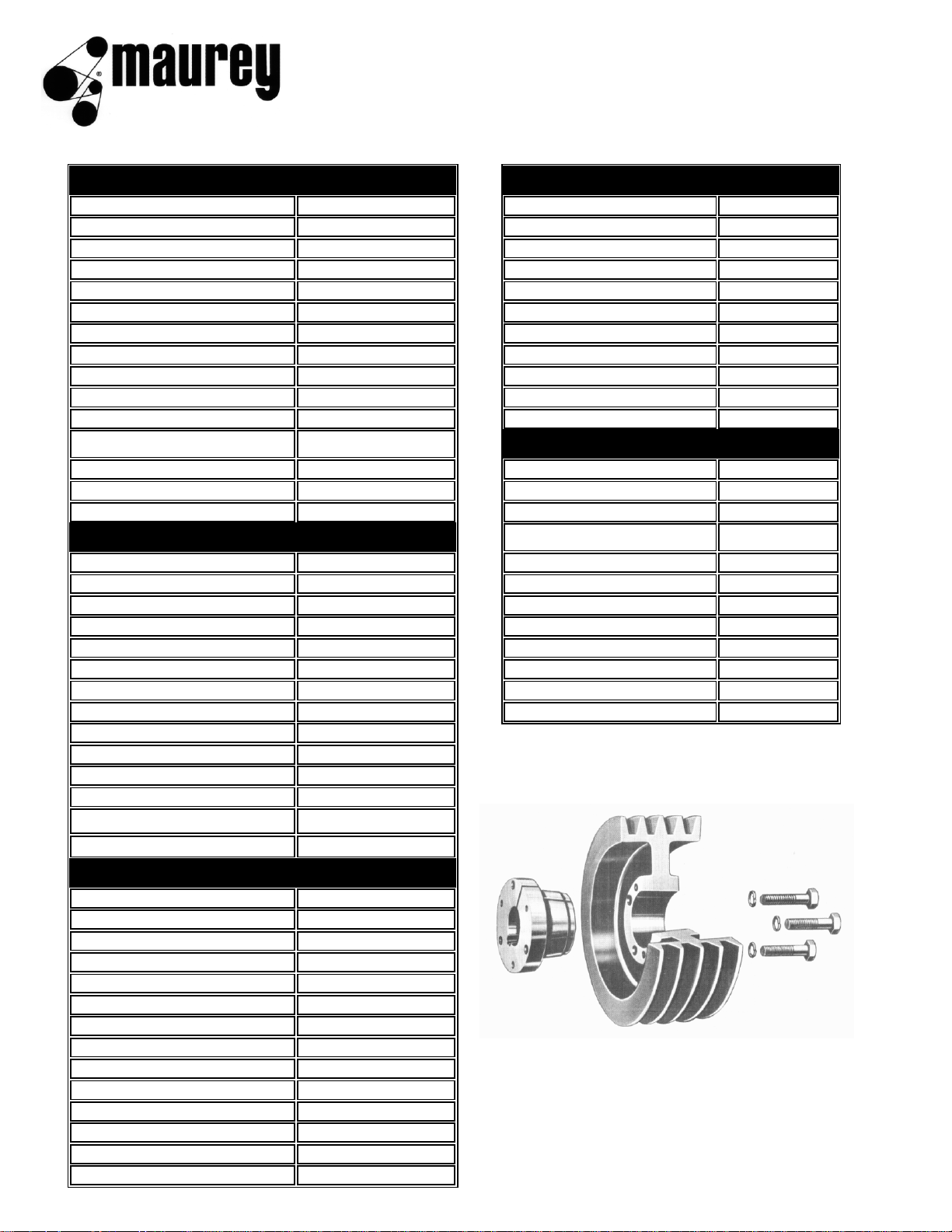
ful-grip bushings
bore and keyseat dimensions
JA BUSHINGS
SK BUSHINGS
BORE SIZES KEY SEAT BORE SIZES KEY SEAT
1/2, 9/16 1/8 X 1/16 1/2, 9/16 1/8 X 1/16
5/8, 11/16, 3/4, 13/16, 7/8 3/16 X 3/32 5/8, 11/16, 3/4, 13/16, 7/8 3/16 X 3/32
15/16, 1 1/4 X 1/8 15/16, 1, 1-1/16, 1-1/8 1/4 X 1/8
1-1/16, 1-1/8, 1-3/16 1/4 X 1/16 1-3/16, 1-1/4 1/4 X 1/8
1-1/4, NONE 1-5/16, 1-3/8 5/16 X 5/32
SH BUSHINGS
1-7/16, 1-1/2, 1-9/16, 1-5/8 3/8 X 3/16
BORE SIZES KEY SEAT 1-11/16, 1-3/4 3/8 X 3/16
1/2, 9/16 1/8 X 1/16 1-13/16, 1-7/8, 1-15/16 1/2 X 1/4
5/8, 11/16, 3/4, 13/16, 7/8 3/16 X 3/32 2, 2-1/16, 2-1/8 1/2 X 1/4
15/16, 1, 1-1/16, 1-1/8 1/4 X 1/8 2-3/16, 2-1/4 1/2 X 1/8
1-3/16, 1-1/4 1/4 X 1/8 2-5/16, 2-3/8, 2-7/16, 2-1/2 5/8 X 1/16
1-5/16, 1-3/8 5/16 X 5/32 2-9/16, 2-5/8 NONE
1-7/16, 1-1/2, 1-9/16, 1-5/8 3/8 X 1/16
SF BUSHINGS
1-11/16, NONE BORE SIZES KEY SEAT
SDS BUSHINGS
1/2, 1/8 X 1/16
BORE SIZES KEY SEAT 5/8, 3/4, 13/16, 7/8 3/16 X 3/32
1/2, 9/16 1/8 X 1/16 15/16, 1, 1-1/16, 1-1/8 1/4 X 1/8
5/8, 11/16, 3/4, 13/16, 7/8 3/16 X 3/32 1-3/16, 1-1/4 1/4 X 1/8
15/16, 1, 1-1/16, 1-1/8 1/4 X 1/8 1-5/16, 1-3/8 5/16 X 5/32
1-3/16, 1-1/4 1/4 X 1/8 1-7/16, 1-1/2, 1-9/16, 1-5/8 3/8 X 3/16
1-5/16, 1-3/8 5/16 X 5/32 1-11/16, 1-3/4 3/8 X 3/16
1-7/16, 1-1/2, 1-9/16, 1-5/8 3/8 X 3/16 1-13/16, 1-7/8, 1-15/16 1/2 X 1/4
1-11/16, 3/8 X 3/16 2, 2-1/16, 2-1/8, 2-3/16, 2-1/4 1/2 X 1/4
1-3/4, 3/8 X 1/8 2-5/16, 2-3/8, 2-7/16, 2-1/2 5/8 X 3/16
1-13/16, 1/2 X 1/8 2-9/16, 2-5/8, 2-11/16, 2-3/4 5/8 X 1/16
1-7/8, 1-15/16 1/2 X 1/16 2-7/8 3/4 X 1/16
2 NONE 2-15/16 3/4 X 1/32
SD BUSHINGS
E BUSHINGS
BORE SIZES KEY SEAT BORE SIZES KEY SEAT
1/2, 9/16 1/8 X 1/16 7/8 3/16 X 3/32
5/8, 11/16, 3/4, 13/16, 7/8 3/16 X 3/32 15/16, 1, 1-1/8 1/4 X 1/8
15/16, 1, 1-1/16, 1-1/8 1/4 X 1/8 1-3/16, 1-1/4 1/4 X 1/8
1-3/16, 1-1/4 1/4 X 1/8 1-5/16, 1-3/8 5/16 X 5/32
1-5/16, 1-3/8 5/16 X 5/32 1-7/16, 1-1/2, 1-9/16, 1-5/8 3/8 X 3/16
1-7/16, 1-1/2, 1-9/16, 1-5/8 3/8 X 3/16 1-11/16, 1-3/4 3/8 X 3/16
1-11/16, 3/8 X 3/16 1-13/16, 1-7/8, 1-15/16 1/2 X 1/4
1-3/4, 3/8 X 1/8 2, 2-1/16, 2-1/8, 2-3/16, 2-1/4 1/2 X 1/4
1-13/16, 1/2 X 1/8 2-5/16, 2-3/8, 2-7/16, 2-1/2 5/8 X 5/16
1-7/8, 1-15/16 1/2 X 1/16 2-9/16, 2-5/8, 2-11/16, 2-3/4 5/8 X 5/16
2 NONE 2-13/16, 2-7/8, 2-15/16, 3 3/4 X 1/8
3-1/8, 3-3/16, 3-1/4 3/4 X 1/8
3-5/16, 3-3/8, 3-7/16, 3-1/2 7/8 X 1/16
C3
ful-grip bushings
bore and keyseat dimensions
F BUSHINGS
N BUSHINGS
BORE SIZES KEY SEAT BORE SIZES KEY SEAT
1, 1-1/8, 1-3/16, 1-1/4 1/4 X 1/8 2-15/16, 3 3/4 X 3/8
1-3/8 5/16 X 5/32 3-3/8, 3-7/16, 3-1/2 7/8 X 7/16
1-7/16, 1-1/2, 1-9/16, 1-5/8 3/8 X 3/16 3-5/8, 3-3/4 7/8 X 7/16
1-3/4 3/8 X 3/16 3-7/8, 3-15/16, 4, 4-3/16 1 X 1/2
1-7/8, 1-15/16 1/2 X 1/4 4-1/4, 4-3/8, 4-7/16, 4-1/2 1 X 1/2
2, 2-1/16, 2-1/8, 2-1/4 1/2 X 1/4 4-5/8, 4-3/4, 4-7/8, 4-15/16 1-1/4 X 5/8
2-5/16, 2-3/8, 2-7/16, 2-1/2 5/8 X 5/16 5 1-1/4 X 5/8
2-9/16, 2-5/8, 2-11/16, 2-3/4 5/8 X 5/16 5-3/16, 5-7/16, 5-1/2, 1-1/4 X 1/4
2-13/16, 2-7/8, 2-15/16, 3 3/4 X 3/8 5-7/8, 1-1/2 X 1/4
3-1/8, 3-3/16, 3-1/4 3/4 X 3/8 5-15/16, 1-1/2 X 1/8
3-5/16, 3-3/8, 3-7/16, 3-1/2 7/8 X 3/16
P BUSHINGS
3-5/8, 3-11/16, 3-3/4 7/8 X 3/16 BORE SIZES KEYSEAT
3-7/8, 3-15/16 1 X 1/8 2-15/16, 3-1/4 3/4 X 3/8
4 NONE 3-7/16, 3-1/2, 3-5/8, 3-3/4 7/8 X 7/16
J BUSHINGS
3-7/8, 3-15/16, 4, 4-1/4 1 X 1/2
BORE SIZES KEY SEAT 4-3/8, 4-7/16, 4-1/2 1 X 1/2
1-7/16, 1-1/2, 1-9/16 3/8 X 3/16 4-5/8, 4-11/16, 4-3/4, 4-7/8, 1-1/4 X 5/8
1-11/16, 1-3/4 3/8 X 3/16 4-15/16, 5, 5-3/16, 5-1/4, 1-1/4 X 5/8
1-7/8, 1-15/16, 2, 2-1/8, 2-1/4 1/2 X 1/4 5-5/16, 5-3/8, 5-7/16, 5-1/2 1-1/4 X 5/8
2-5/16, 2-3/8, 2-7/16, 2-1/2 5/8 X 5/16 5-3/4, 1-1/2 X 3/4
2-5/8, 2-11/16, 2-3/4 5/8 X 5/16 5-7/8, 5-15/16, 6, 6-1/16 1-1/2 X 1/4
2-7/8, 2-15/16, 3 3/4 X 3/8 6-1/4, 6-7/16, 6-1/2 1-1/2 X 1/4
3-1/8, 3-3/16, 3-1/4 3/4 X 3/8 6-3/4, 7 1-3/4 X 1/8
3-5/16, 3-3/8, 3-7/16, 3-1/2 7/8 X 7/16
3-5/8, 3-11/16, 3-3/4 7/8 X 7/16
3-13/16, 1 X 1/2
3-7/8, 3-15/16 1 X 3/8
4, 4-1/8, 4-3/16, 4-1/4, 4-3/8 1 X 1/8
4-7/16, 4-1/2 1 X 1/8
M BUSHINGS
BORE SIZES KEY SEAT
1-15/16, 2, 2-3/16, 2-1/4 1/2 X 1/4
2-3/8, 2-7/16, 2-1/2 5/8 X 5/16
2-5/8, 2-11/16, 2-3/4 5/8 X 5/16
2-7/8, 2-15/16, 3 3/4 X 3/8
3-1/8, 3-3/16, 3-1/4 3/4 X 3/8
3-3/8, 3-7/16, 3-1/2 7/8 X 7/16
3-5/8, 3-11/16, 3-3/4 7/8 X 7/16
3-7/8, 3-15/16, 4 1 X 1/2
4-1/8, 4-3/16, 4-1/4, 4-3/8 1 X 1/2
4-7/16, 4-1/2 1 X 1/2
4-11/16 1-1/4 X 5/8
4-3/4, 4-7/8, 4-15/16, 5 1-1/4 X 1/4
5-3/16, 5-1/4, 5-7/16, 5-1/2 1-1/4 X 1/4
C4
ful-grip bushings
bore and keyseat dimensions
METRIC STOCK BORE INFORMATION
JA BUSHINGS SK BUSHINGS F BUSHINGS
BORE (MM) KEYWAY BORE (MM) KEYWAY BORE (MM) KEYWAY
12 NONE 24, 25, 28, 30 8 X 7 45, 48, 50 14 X 9
15, 17 5 X 5 32, 35, 38 10 X 8 55 16 X 10
19, 20, 22 6 X 6 40, 42 12 X 8 60, 65 18 X 11
24 8 X 6 45, 48, 50 14 X 9 70, 75 20 X 12
28 8 X 5 55 16 X 10 80, 85 22 X 14
SH BUSHINGS SF BUSHINGS
90 25 X 14
BORE (MM) KEYWAY BORE (MM) KEYWAY
19 6 X 6 28, 30 8 X 7 BORE (MM) KEYWAY
24, 25, 28, 30 8 X 7 32, 35, 38 10 X 8 50 14 X 9
32, 35 10 X 8 40, 42 12 X 8 55 16 X 10
SDS BUSHINGS
45, 48, 50 14 X 9 60, 65 18 X 11
BORE (MM) KEYWAY 55 16 X 10 70, 75 20 X 12
24, 25, 28, 8 X 7 60 18 X 11 80, 85 22 X 14
30, 32 8 X 7 65 18 X 8 * 90, 95 25 X 14
35, 38 10 X 8
E BUSHINGS
100 28 X 16
40, 42 12 X 8 BORE (MM) KEYWAY
M BUSHINGS
SD BUSHINGS
35, 38 10 X 8 BORE (MM) KEYWAY
BORE (MM) KEYWAY 40, 42 12 X 8 80 22 X 14
24, 25, 28, 30 8 X 7 45, 48, 50 14 X 9 90 25 X 14
35, 38 10 X 8 55 16 X 10 100 28 X 16
40, 42 12 X 8 60, 65 18 X 11 120 32 X 18
70, 75 20 X 12
80 22 X 11
*- SHALLOW KEYSTOCK REQUIRED
The "Keyway" dimensions shown refer to the dimensions of the keystock not the keyway. The keyway is
manufactured to accommodate this keystock size. This nomenclature is in accordance with metric
standards.
J BUSHINGS
C5

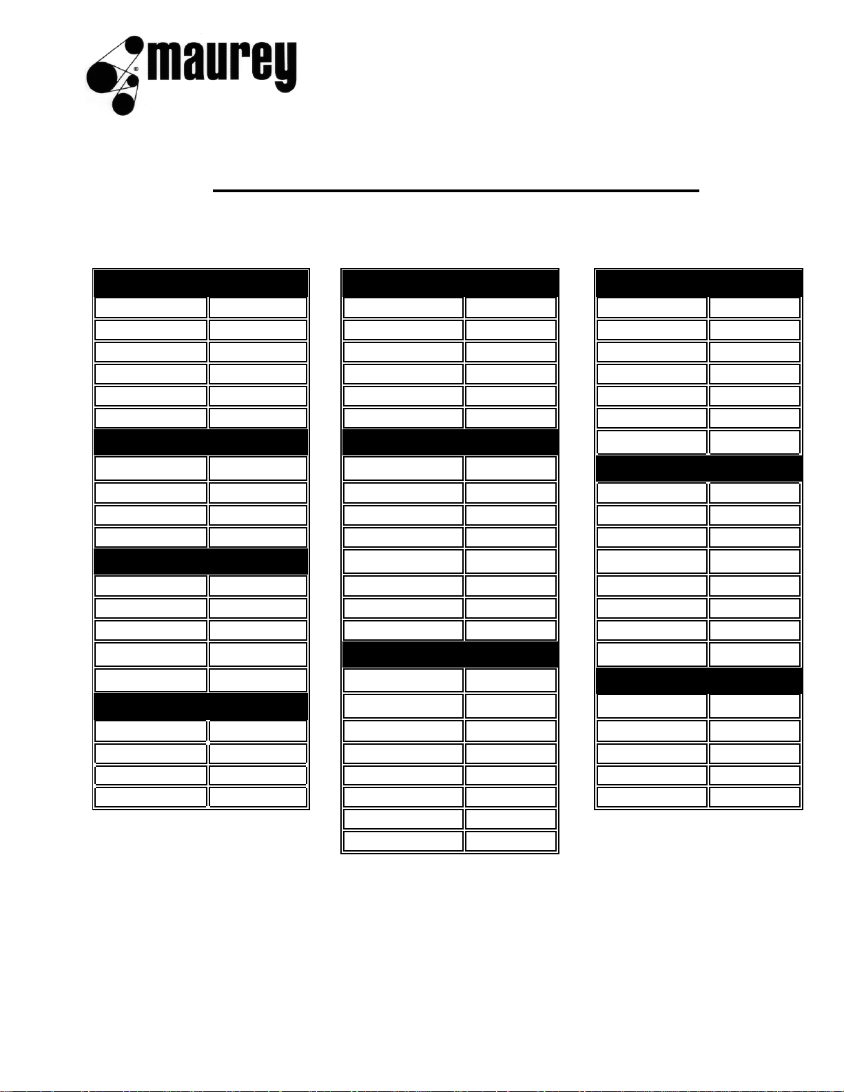
STANDARD MOUNTING ASSEMBLY
REVERSE MOUNTING ASSEMBLY
Fig. 1 Fig. 2
INSTALLATION AND REMOVAL OF QD SHEAVES
INSTALLATION REMOVAL
1. Make sure the bore of the sheave and the tapered cone 1. Loosen and remove cap screws.
surface of the bushing are free of all the foreign sub- 2. Insert cap screws in tapered removal holes and starting
stances such as paint, dirt, lubricants, etc. Do not use
with bolt farthest from sawnut on bushing, tighten evenly
lubricants on installation. and progressively until sheave is loose on bushing. If
2. Assemble bushings and sheave as shown above in Fig- sheaves in Figure 2 are installed with cap screw heads
ures 1 and 2, whichever applies. With cap screws loosely next to motor, loosen cap screws and use a wedge
inserted, the bushing remains fully expanded to assume between the bushing and the sheave.
a sliding fit on the shaft. Note: When installing bushings 3. Remove sheave and bushing
M thru S, locate the extra holes in the hub as far as possible from the bushing's saw cut in order to reduce the CAUTION: Excessive or unequal pressure on the jack
possibility of bushing flange breakage. CAUTION: Do
screws can break the bushing flange
not use lubricants on screw threads or tapered surfaces
3. With key on shaft, slide sheave assembly to its desired
position with cap screw heads on outside. (Exception:
Some shaft lengths may require the sheaves to be
reversed with the cap screw heads to the inside - see
Figure 2.) Wrench Wrench Wrench
4. Line up the sheave assembly and tighten cap screws Bushing Torque Length Pull
evenly and progressively to the torque value listed in the (In.-Lbs) (Inches) (Pounds)
table. Never allow the sheave to be drawn in contact with JA 60 4 15
the bushing flange. There should be a gap of 1/8" to 1/4" SH 108 4 27
between the sheave hub and the bushing flange. If the gap SDS 108 4 27
is closed, the shaft is seriously undersize. SDS 108 4 27
5. Tighten the set screw to hold the key securely on the SK 180 6 30
shaft during operation.
SF 360 6 60
CAUTION: When mounting a "FUL-GRIP" bushing, the E 720 12 60
tightening force of the screws is multiplied may times by F 900 12 75
the wedging action of the tapered surface. This action J 1620 12 135
compresses the bushing for a snug fit on the shaft. If M 2700 15 180
extreme screw tightening forceor lubricants are applied in
mounting the "FUL-GRIP" bushing, bursting pressures will N 3600 15 240
be created in the hub of the mounted sheave which may P 5400 18 300
cause it to crack.
Refer to the recommended torque ratings
C6
 Loading...