

Page 1

PУКОВОДСТВО ПО ЭКСПЛУАТАЦИИ
INSTRUCTION OF USE
NOTICE D’UTILISATION
СТЕКЛОКЕРАМИЧЕСКАЯ ПАНЕЛЬ
MVI592FL-BK
MVI592FL-GR
MVI592FL-WH
Page 2

Page 3

3
Уважаемый покупатель,
Благодарим Вас за выбор индукционной керамической варочной панели.
Для того чтобы Вы могли наилучшим образом использовать приобретенное Вами
устройство, рекомендуем Вам внимательно ознакомиться с содержанием данной
инструкции, сохранить ее и обращаться к ней в будущем по мере возникновения вопросов.
СОДЕРЖАНИЕ
БЕЗОПАСНОСТЬ ........................................................................................................................ 4
ПРЕДВАРИТЕЛЬНЫЕ МЕРЫ ПРЕДОСТОРОЖНОСТИ .......................................................................... 4
ЭКСПЛУАТАЦИЯ ОБОРУДОВАНИЯ .................................................................................................. 5
МЕРЫ ПО СОХРАННОСТИ ОБОРУДОВАНИЯ ..................................................................................... 6
МЕРЫ В СЛУЧАЕ НЕИСПРАВНОСТИ ОБОРУДОВАНИЯ ....................................................................... 7
ДРУГИЕ МЕРЫ ПРЕДОСТОРОЖНОСТИ ............................................................................................ 7
ОПИСАНИЕ ОБОРУДОВАНИЯ .................................................................................................. 8
ТЕХНИЧЕСКИЕ ХАРАКТЕРИСТИКИ .................................................................................................. 8
ПАНЕЛЬ УПРАВЛЕНИЯ .................................................................................................................. 9
ЭКСПЛУАТАЦИЯ ОБОРУДОВАНИЯ ......................................................................................... 9
ДИСПЛЕЙ .................................................................................................................................... 9
ВЕНТИЛЯЦИЯ............................................................................................................................... 9
ЗАПУСК И КОНТРОЛЬ ОБОРУДОВАНИЯ .............................................................................. 10
ПЕРЕД ПЕРВЫМ ВКЛЮЧЕНИЕМ .................................................................................................... 10
ПРИНЦИП ИНДУКЦИИ .................................................................................................................. 10
СЕНСОРНАЯ ПАНЕЛЬ .................................................................................................................. 10
ШКАЛА-ПОЛЗУНОК ("СЛАЙДЕР") УСТАНОВКИ МОЩНОСТИ И ТАЙМЕРА ............................................. 11
ЗАПУСК ..................................................................................................................................... 11
ОБНАРУЖЕНИЕ ПОСУДЫ ............................................................................................................. 12
ИНДИКАЦИЯ ОСТАТОЧНОГО НАГРЕВА .......................................................................................... 12
ФУНКЦИЯ "BOOSTER" ................................................................................................................. 12
ТАЙМЕР .................................................................................................................................... 13
АВТОМАТИЧЕСКОЕ ПРИГОТОВЛЕНИЕ ПИЩИ ................................................................................. 14
ФУНКЦИЯ "ПАУЗА" ..................................................................................................................... 15
ФУНКЦИЯ "ВОЗВРАТ" ................................................................................................................. 15
ФУНКЦИЯ "МОСТ" ...................................................................................................................... 15
ФУНКЦИЯ СОХРАНЕНИЯ ТЕПЛА ................................................................................................... 16
БЛОКИРОВКА ПАНЕЛИ УПРАВЛЕНИЯ ............................................................................................ 16
СОВЕТЫ ПО ПРИГОТОВЛЕНИЮ ПИЩИ ................................................................................ 17
КАЧЕСТВО ПОСУДЫ ................................ ................................ ................................ .................... 17
РАЗМЕРЫ ПОСУДЫ ................................................................................................ ..................... 17
ПРИМЕРЫ НАСТРОЙКИ МОЩНОСТИ КОНФОРОК ............................................................................ 18
УХОД И ОЧИСТКА ..................................................................................................................... 18
УСТРАНЕНИЕ НЕИСПРАВНОСТЕЙ ........................................................................................ 18
ОХРАНА ОКРУЖАЮЩЕЙ СРЕДЫ ........................................................................................... 19
ИНСТРУКЦИИ ПО УСТАНОВКЕ ............................................................................................... 20
ЭЛЕКТРИЧЕСКОЕ ПОДКЛЮЧЕНИЕ ........................................................................................ 21
Page 4

4
БЕЗОПАСНОСТЬ
Предварительные меры предосторожности
• Удалите весь упаковочный материал.
• Установка и подключение данного оборудования должны
проводиться только квалифицированными специалистами.
Производитель не несёт ответственность за ущерб,
причиненный вследствие ошибок при встраивании
оборудования или его подключении к электрической сети.
• Данное оборудование может использоваться только будучи
установленным в должным образом оборудованный
комплект кухонной мебели с подходящими рабочими
поверхностями, сертифицированными для использования с
данным оборудованием.
• Данное бытовое оборудование предназначено
исключительно для приготовления пищи, при этом любое
иное бытовое, коммерческое или промышленное
использование данного оборудования запрещено.
• Снимите все этикетки и самоклеящуюся плёнку со
стеклокерамической поверхности.
• Не изменяйте технические параметры и не вносите
изменение в конструкцию данного оборудования.
• Запрещается автономная эксплуатация варочной панели, а
также её использование в качестве рабочей поверхности.
• Данное оборудование должно быть подключено к
электрической сети и заземлено в соответствии с местными
стандартами.
• Не используйте удлинитель для подключения данного
оборудования к электрической сети.
• Размещение данного оборудования над посудомоечной или
сушильной машиной запрещается, так как пар может
повредить электронные компоненты данного оборудования.
• Данное оборудование не предназначено для эксплуатации
посредством внешнего таймера или отдельной системы
дистанционного управления.
• ПРЕДОСТЕРЕЖЕНИЕ: Процесс кулинарии должен
контролироваться. Необходимо постоянно контролировать
процесс кулинарии.
Page 5

5
Эксплуатация оборудования
• Выключайте конфорки после использования оборудования.
• Будьте внимательны при использовании масла или жира
для приготовления пищи, поскольку они легко
воспламеняются.
• Будьте осторожны, чтобы не обжечься во время или после
использования оборудования.
• Не допускайте контакта проводов какого-либо
стационарного или передвижного оборудования со
стеклокерамической поверхностью или горячей посудой.
• Размещение источников магнитного поля (кредитных карт,
дискет, калькуляторов) вблизи работающего оборудования
запрещено.
• Размещение на конфорках металлических предметов
(ножей, вилок, ложек, крышек и т.п.) запрещено, так как они
могут нагреться.
• Используйте специальную посуду для индукционных
варочных панелей. Запрещается размещение на
стеклокерамической поверхности любых металлических
предметов, за исключением термостойких контейнеров.
Если оборудование включено слишком быстро, или при
наличии остаточного тепла, другие материалы могут
расплавиться или воспламениться.
• Никогда не накрывайте оборудование тканью или
защитным чехлом, поскольку они могут сильно нагреться и
воспламениться.
• Данное оборудование может использоваться детьми
старше 8 лет и лицами с ограниченными физическими,
сенсорными и умственными способностями, а также с
недостаточными опытом и знаниями, если они получили
инструкции по безопасному использованию оборудования и
осознают возможные опасности.
• Не позволяйте детям играть с оборудованием.
• Очистка и уход за оборудованием не должны
осуществляться детьми без присмотра.
Page 6

6
Меры по сохранности оборудования
• Посуда с днищем из обычного металла или с
повреждённым дном (к примеру, не эмалированная
чугунная посуда) может повредить стеклокерамическую
поверхность.
• Песок или другие абразивные материалы могут повредить
стеклокерамическую поверхность.
• Не допускайте падения предметов, даже небольших, на
стеклокерамическую поверхность.
• Не бейте посудой по краям стеклокерамической
поверхности.
• Убедитесь, что вентиляционная система оборудования
работает в соответствии с инструкцией заводаизготовителя.
• Не ставьте и не оставляйте пустую посуду на
стеклокерамической поверхности.
• Сахар, синтетические материалы или алюминиевые листы
не должны подвергаться воздействию тепла от горячих
конфорок, поскольку при охлаждении они могут вызвать
трещины или другие повреждения стеклокерамической
поверхности. Следует выключить оборудование и
немедленно удалить их (будьте осторожны, чтобы не
обжечься).
• ВНИМАНИЕ: опасность воспламенения: не размещайте
предметы на варочной поверхности.
• Никогда не ставьте горячие контейнеры на панель
управления.
• Если под встроенным оборудованием расположен
выдвижной ящик, убедитесь, что зазор между содержимым
ящика и нижней частью устройства достаточно велик (2 см).
Это необходимо для обеспечения правильной вентиляции.
• Никогда не кладите легковоспламеняющиеся предметы и
вещества (к примеру, аэрозоли) в ящик, расположенный
под стеклокерамической варочной панелью. Ящики для
хранения столовых приборов должны быть сделаны только
из термостойких материалов.
Page 7
7
Меры в случае неисправности оборудования
• В случае неисправности, выключите устройство и
отключите электропитание.
• Если стеклокерамическая поверхность разбита или на ней
имеются трещины, отключите устройство от сети
электропитания и обратитесь в сервисный центр.
• Ремонт данного оборудования должен производиться
квалифицированными специалистами. Не открывайте
корпус устройства самостоятельно.
• ВНИМАНИЕ: если стеклокерамическая поверхность
разбита или на ней имеются трещины, во избежание
поражения электрическим током, выключите устройство.
Другие меры предосторожности
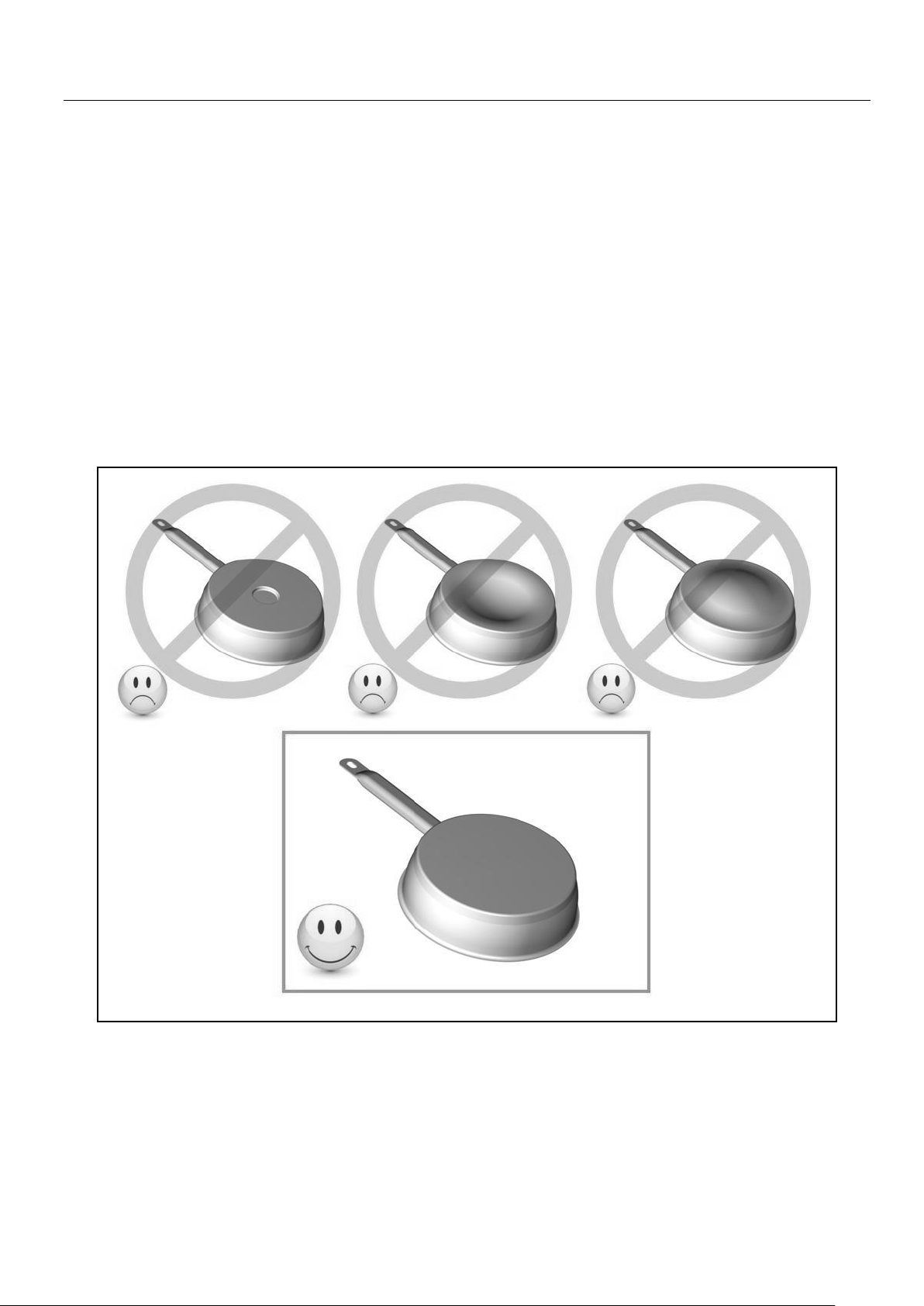
• Убедитесь, что посуда расположена по центру конфорки.
Днище посуды должно закрывать как можно большую
поверхность конфорки.
• Лицам, пользующимся электрокардиостимулятором,
следует иметь в виду, что магнитное поле может влиять на
его работу. Рекомендуется получить консультацию у
продавца или врача.
• Не используйте контейнеры из алюминия или
синтетических материалов, поскольку они могут
расплавиться на горячих конфорках.
• НИКОГДА не пытайтесь потушить пламя водой, сначала
выключите устройство, а затем закройте пламя крышкой
или пожарным покрывалом.
ИСПОЛЬЗОВАНИЕ ПОСУДЫ НИЗКОГО КАЧЕСТВА
ИЛИ ИНДУКЦИОННЫХ АДАПТЕРНЫХ ПЛАСТИН ДЛЯ
НЕМАГНИТНЫХ КУХОННЫХ ПЛИТ ПРИВОДИТ К
АННУЛИРОВАНИЮ ГАРАНТИИ.
В ДАННОМ СЛУЧАЕ, ИЗГОТОВИТЕЛЬ НЕ НЕСЕТ
КАКОЙ-ЛИБО ОТВЕТСТВЕННОСТИ ЗА УЩЕРБ,
ПРИЧИНЕННЫЙ ВАРОЧНОЙ ПАНЕЛИ И/ИЛИ
ДРУГОМУ ИМУЩЕСТВУ.
Page 8

8
ОПИСАНИЕ ОБОРУДОВАНИЯ
Технические характеристики
Тип
MVI592FL-BK/GR/WH
Полная мощность
7400 Вт
Потребление энергии поверхностью EC
hob
**
172.8 Втч/кг
Передняя левая pасположение конфорок
195x195 мм
Минимальный обнаруживаемый диаметр
Ø 100 мм
Номинальная мощность*
1400 Вт
Мощность в режиме быстрого нагрева*
1850 Вт
Категория стандартного оборудования **
C
Потребление энергии ECcw **
172.7 Втч/кг
Задняя левая pасположение конфорок
195x195
Минимальный обнаруживаемый диаметр
Ø 100 мм
Номинальная мощность*
1400 Вт
Мощность в режиме быстрого нагрева*
1850 Вт
Категория стандартного оборудования **
C
Потребление энергии ECcw **
172.7 Втч/кг
Задняя правая pасположение конфорок
195x195
Минимальный обнаруживаемый диаметр
Ø 100 мм
Номинальная мощность*
1400 Вт
Мощность в режиме быстрого нагрева*
1850 Вт
Категория стандартного оборудования **
B
Потребление энергии ECcw **
164 Втч/кг
Передняя правая pасположение конфорок
195x195
Минимальный обнаруживаемый диаметр
Ø 100 мм
Номинальная мощность*
1400 Вт
Мощность в режиме быстрого нагрева*
1850 Вт
Категория стандартного оборудования **
A
Потребление энергии ECcw **
181.6 Втч/кг
* Указанная мощность может изменяться в зависимости от размеров и материала посуды.
** рассчитано согласно методике измерений (EN 60350-2).
Page 9
9
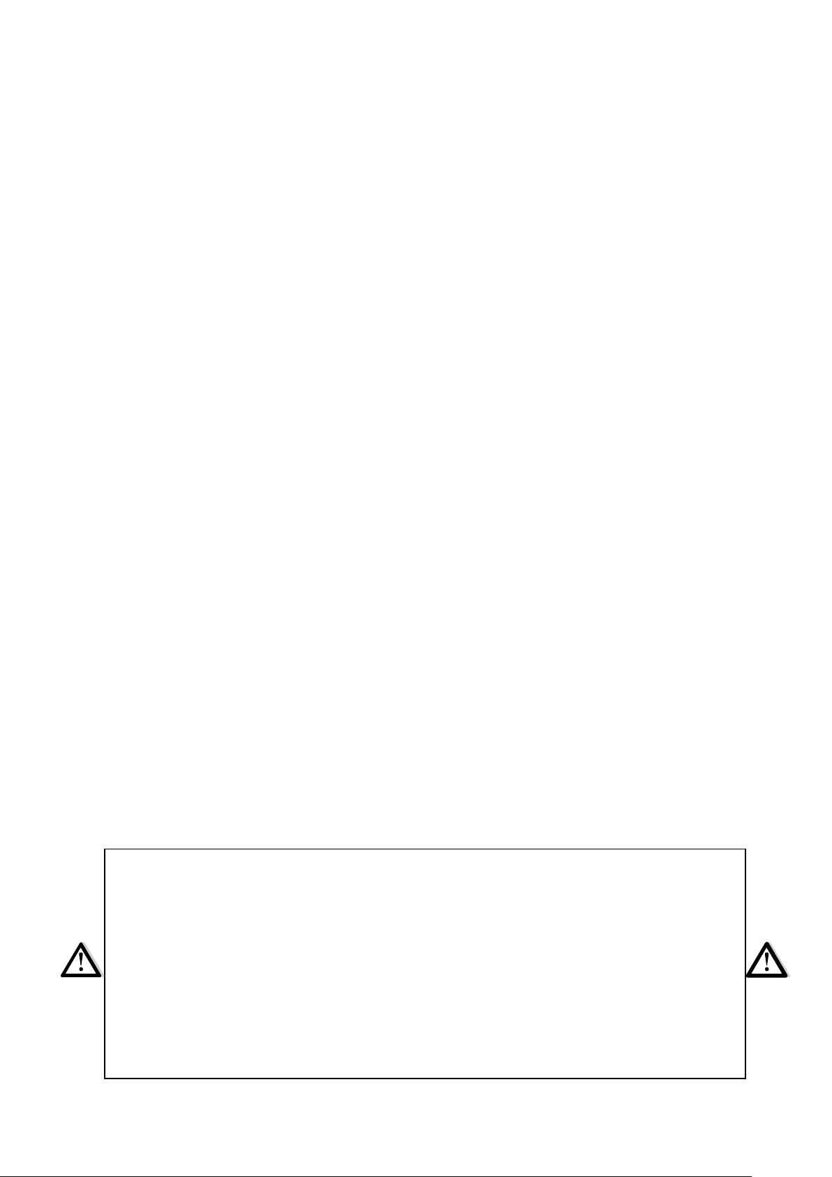
Панель управления
ЭКСПЛУАТАЦИЯ ОБОРУДОВАНИЯ
Дисплей
Дисплей Назначение Функция
0 Нуль Включение конфорки.
1…9 Уровень мощности Задание уровня нагрева конфорки.
U Наличие посуды Посуда отсутствует или не подходит.
A Ускорение нагрева Автоматическое приготовление пищи.
E Сообщение об ошибке Неисправность электронной аппаратуры.
H Остаточное тепло Конфорка горячая.
P "Booster" Режим усиленного нагрева.
L Блокировка Блокировка панели управления.
U Сохранение тепла Автоматическое поддержание температуры 70°C.
II Пауза Переход в режим паузы.
∏ Функция "Мост" Режим "Мост".
Вентиляция
Система охлаждения работает постоянно. Вентилятор запускается при включении
варочной панели и увеличивает скорость при интенсивной работе варочной панели.
Вентилятор охлаждения снижает скорость и автоматически останавливается при
достаточном охлаждении электрических цепей.
Опция "сохранять
тепло"
Кнопка
"Booster"
Кнопка
"Пауза/Возврат"
Контрольный
индикатор
(конфорка)
Контрольный
индикатор (таймер)
Таймер
Шкала-ползунок ("слайдер")
установки мощности и таймера
Мощность
Контрольный
индикатор
(вкл./выкл.)
Кнопка
"Вкл./Выкл."
Контрольный
индикатор
(пауза/возврат)
Page 10

10
ЗАПУСК И КОНТРОЛЬ ОБОРУДОВАНИЯ
Перед первым включением
Тщательно очистите варочную панель сначала влажной тканью, а затем сухой. Не
используйте растворители, поскольку они могут вызвать окрашивание стеклянной
поверхности в синий цвет.
Принцип индукции
Катушка индуктивности расположена под каждой конфоркой. При включении она создает
переменное электромагнитное поле, которое вызывает индуктивные токи в
ферромагнитном днище кухонной посуды. Результатом является нагрев посуды на
конфорке.
Требования к посуде:
• Рекомендуется использовать посуду из ферромагнитных материалов (проверьте
намагничивание с помощью небольшого магнита): чугунная и стальная посуда,
эмалированная посуда, посуда из нержавеющей стали с ферромагнитным дном…
• Не допускается использовать посуду из: меди, чистой нержавеющей стали,
алюминия, стекла, дерева, керамики, каменной керамики,…
Индукционная зона нагрева автоматически адаптируется под размер посуды. Посуда
слишком малого диаметра не нагревается. Диаметр индукционной зоны изменяется в
зависимости от диаметра посуды.
Если посуда не подходит для индукционной варочной панели, на дисплее отображается
символ [ U ].
Сенсорная панель
Варочная панель оснащена электронной панелью управления с сенсорными кнопками.
Соответствующая команда активируется при нажатии на сенсорную кнопку пальцем.
Срабатывание кнопки подтверждается контрольным индикатором, символом или цифрой
на дисплее и/или звуковым сигналом.
В большинстве случаев требуется нажатие только одной кнопки за раз.
Page 11

11
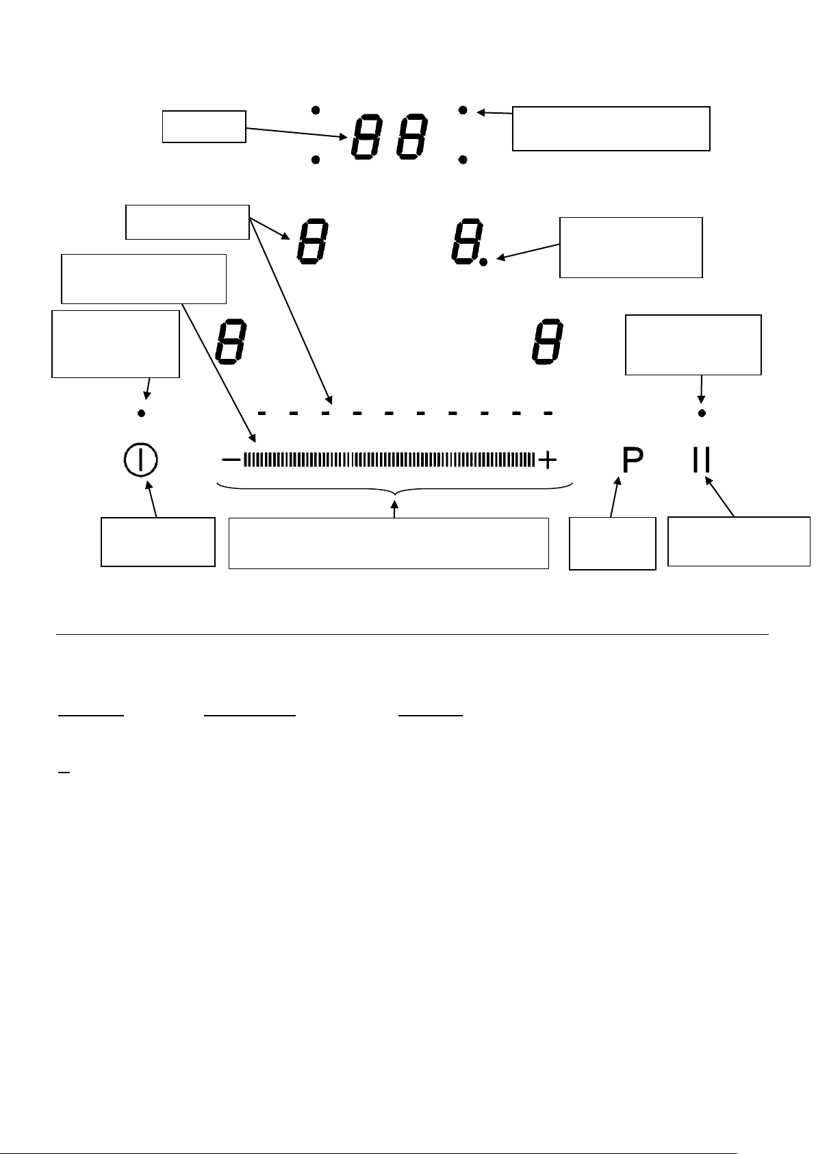
Шкала-ползунок ("слайдер") установки мощности и таймера
Для выбора мощности с помощью слайдера, поставьте на него палец. Если коснуться
пальцем места, соответствующего определённому уровню мощности, данный уровень
задаётся сразу.
Запуск
Сначала необходимо включить варочную панель, затем – конфорку:
• Включение/выключение устройства:
Действие Панель управления Дисплей
Включение Нажмите кнопку [ ] [ 0 ] мигает
Выключение Нажмите кнопку [ ] нет символа или [ H ]
• Включение/выключение конфорки:
Действие Панель управления Дисплей
Выбор конфорки Нажмите [ 0 ] для выбора [ 0 ] (горит
Контрольный
индикатор)
Установка Передвиньте слайдер [ 0 ] − [ 9 ]
(настройка мощности) вправо или влево
Выключение Передвиньте слайдер на [ 0 ] [ 0 ] или [ H ]
или нажмите [ 0 ] [ 0 ] или [ H ]
Если в течение 20 секунд не производится никаких действий, электронные системы
оборудования переводят его в режим ожидания.
Шкала-ползунок ("слайдер")
установки мощности и таймера
Слайдер
Прямой выбор
Page 12

12
Обнаружение посуды
Функция обнаружения посуды служит для обеспечения безопасной работы. Индукционный
нагрев не работает:
• Если на конфорке нет посуды, или если посуда не предназначена для индукционных
плит. В данном случае мощность не может быть увеличена или уменьшена, и на
дисплее отображается символ [ U ]. Этот символ удаляется с дисплея после того,
как посуда поставлена на конфорку.
• Если посуда снята с конфорки – нагрев прекращается. На дисплее отображается
символ [ U ]. Символ [ U ] удаляется с дисплея, если посуду поставить обратно на
конфорку. Нагрев продолжается с ранее заданным уровнем мощности.
После приготовления пищи обязательно отключайте нагревательный элемент: не оставляйте
функцию обнаружения [ U ] постоянно включенной.
Индикация остаточного нагрева
После отключения конфорки или полного отключения варочной панели конфорки остаются
горячими, и на дисплее отображается символ [ H ].
После удаления символа [ H ] с дисплея конфорки имеют безопасную температуру и к ним
можно прикасаться.
Если на дисплее отображается символ остаточной теплоты, не прикасайтесь к конфоркам
и не кладите на них термочувствительные предметы. Опасность возгорания и пожара.
Функция "Booster"
Функция "Booster" [P] переводит выбранную конфорку в режим усиленного нагрева.
При включении этой функции, конфорки в течение 5 минут работают на сверхвысокой
мощности.
Указанная функция используется, к примеру, для быстрого нагрева большого объёма воды
при приготовлении лапши.
• Включение/выключение функции "Booster":
Действие Панель управления Дисплей
Выбор конфорки Нажмите [ 0 ] для выбора [ 0 ] (горит
Контрольный
индикатор)
"Booster" вкл. Нажмите кнопку [P] [ P ]
"Booster" выкл. Передвиньте слайдер [ P ] − [ 0 ]
или нажмите [P] [ 9 ]
• Управление мощностью:
Оборудование имеет общий предел мощности. Если на одной из конфорок активирована
функция "Booster", чтобы не превысить указанный предел, электронные системы
оборудования автоматически уменьшают мощность на другой конфорке. P течение
нескольких секунд на дисплее мигает символ [ 9 ], после чего отображается максимально
допустимая мощность:
Выбранная конфорка Другая конфорка: (пример: уровень мощности 9)
Отображается [ P ] [ 9 ] − [ 6 ] или [ 8 ] (в зависимости от типа конфорки)
Page 13

13
Таймер
Таймер может использоваться одновременно со всеми конфорками, при этом время
работы (от 0 до 99 минут) может быть задано отдельно для каждой конфорки.
• Установка и изменение времени приготовления пищи:
Пример: 16 минут, уровень мощности 7:
Действие Панель управления Дисплей
Выбор конфорки Нажмите [ 0 ] для выбора [ 0 ] (горит
Контрольный
индикатор)
Установка мощности Передвиньте слайдер на [ 7 ] [ 7 ]
Вход в меню таймера Нажмите [ CL ] на дисплее [ 00 ]
Установка минут Передвиньте слайдер на [ 6 ] [ 0 горит ] [ 6 мигает ]
Подтверждение (минуты) Нажмите [ 06 ] на дисплее [ 0 мигает ] [ 6 горит ]
Установка десятков минут Передвиньте слайдер на [ 1 ] [ 1 мигает ] [ 6 горит ]
Подтверждение
(десятки минут) Нажмите [ 16 ] на дисплее [ 16 ]
Таким образом, заданное время подтверждено, после чего начинается приготовление пищи.
• Остановка отсчёта времени приготовления пищи:
Пример: 16 минут, уровень мощности 7:
Действие Панель управления Дисплей
Выбор конфорки Нажмите [ 7 ] для выбора [ 0 ] (горит
Контрольный
индикатор)
Вход в меню таймера Нажмите [ 16 ] [ 16 ]
Сброс минут Передвиньте слайдер на [ 0 ] [ 1 горит ] [ 0 мигает ]
Подтверждение (сброс минут) Нажмите [ 10 ] на дисплее [ 1 мигает ] [ 0 горит ]
Сброс десятков минут Передвиньте слайдер на [ 0 ] [ 0 мигает ] [ 0 горит ]
Подтверждение
(сброс десятков минут) Нажмите [ 00 ] на дисплее [ 00 ]
• Автоматическое отключение по завершении отсчёта времени приготовления
пищи:
После того, как заданное время приготовления пищи заканчивается, на дисплее мигают
символы [ 00 ], и звонит звонок.
Для выключения звонка и прекращения мигания достаточно нажать кнопку [ 00 ].
Page 14

14
• Таймер обратного отсчёта:
Пример: 29 минут:
Действие Панель управления Дисплей
Включение Нажмите [ ] на дисплее Горят контрольные
индикаторы конфорки
Вход в меню таймера Нажмите [ CL ] на дисплее [ 00 ]
Установка минут Передвиньте слайдер на [ 9 ] [ 0 горит ] [ 9 мигает ]
Подтверждение (минуты) Нажмите [ 09 ] на дисплее [ 0 мигает ] [ 9 горит ]
Установка десятков минут Передвиньте слайдер на [ 2 ] [ 2 мигает ] [ 9 горит ]
Подтверждение
(десятки минут) Нажмите [ 29 ] на дисплее [ 29 ]
Через несколько секунд контрольный индикатор прекращает мигать.
После того, как заданное время приготовления пищи заканчивается, на дисплее мигают
символы [ 00 ], и звонит звонок.
Для выключения звонка и прекращения мигания достаточно нажать кнопку [ 00 ].
Оборудование выключается.
Автоматическое приготовление пищи
Все конфорки оборудованы устройством автоматического включения и отключения.
Конфорка включается, в течение определённого времени работает на полной мощности,
после чего автоматически снижает мощность до заранее заданного уровня.
• Включение:
Действие Панель управления Дисплей
Выбор конфорки Нажмите [ 0 ] для выбора [ 0 ] (горит
Контрольный
индикатор)
Установка полной мощности Передвиньте слайдер на [ 9 ] [ 0 ] − [ 9 ]
Автоприготовление пищи Нажмите [ 9 ] на слайдере Мигают символы [ 9 ]
и [ A ]
Выбор уровня мощности Передвиньте слайдер на [ 7 ] [ 9 ] − [ 8 ] − [ 7 ]
(к примеру, “ 7 “) Мигают символы [ 7 ]
и [ A ]
• Выход из режима автоматического приготовления пищи:
Действие Панель управления Дисплей
Выбор конфорки Нажмите [ 7 ] в меню конфорки Мигают символы [ 7 ]
и [ A ]
Выбор уровня мощности Передвиньте слайдер
на нужное значение [ 1 ] − [ 9 ]
Page 15
15
Функция "Пауза"
Данная функция полностью приостанавливает приготовление пищи и позволяет
перезапустить оборудование с прежними настройками.
• Активация/деактивация функции "Пауза":
Действие Панель управления Дисплей
Активация функции "Пауза" Нажмите и держите кнопку В меню конфорки
"Пауза/Возврат" 2 секунды отображается [ II ]
Деактивация функции "Пауза" Нажмите и держите кнопку Контрольный
"Пауза/Возврат" 2 секунды индикатор
Нажмите другую кнопку или режима паузы мигает
передвиньте слайдер Контрольный
индикатор режима
паузы не горит
Функция "Возврат"
После отключения оборудования ( кнопка ), возможно вернуться к прежним настройкам:
• режимов на всех конфорках (уровней мощности)
• заданным настройкам (минуты, секунды) таймеров для каждой конфорки
• режима нагрева
Вызов функции "Возврат" осуществляется следующим образом:
• Нажмите кнопку [ ]
• Нажмите и удерживайте нажатой кнопку [II] в течение 6 секунд
Произойдёт возврат к прежним настройкам.
Функция "Мост"
Данная функция позволяет использовать 2 боковых конфорки как одну. Использование
функции
Действие Панель управления Дисплей
Включение устройства Нажмите кнопку [ ] на дисплее [ 0 ] или [ H ]
(выводится
на 4 дисплея)
Активация функции "Мост" Нажмите на значки двух В зоне двух выбранных
левых или правых конфорок конфорок
отображается
символ [ ∏ ];
на остальных [ 0 ].
Повышение мощности Передвиньте слайдер на [ 1 − 9 ] или [ U ]
[ 1 − 9 ] или нажмите
[сохранять тепло] на дисплее
Деактивация функции "Мост" Нажмите на значки 2 конфорок На 2 дисплея
конфорок
которые соеденены мостом выводится [ 0 ]
или [ H ]
Page 16

16
Функция сохранения тепла
Данная функция позволяет осуществить нагрев и поддерживать температуру в 70°C в
автоматическом режиме, благодаря чему жидкость не переливается через край посуды, а
также предотвращается быстрое подгорание.
• Активация функции сохранения тепла:
Действие Панель управления Дисплей
Выбор конфорки Нажмите кнопку [ 0 ] на дисплее [ 0 ] − [ 9 ] или [ H ]
Активация
сохранения тепла Нажмите [сохранять тепло]
на слайдере [ U ]
Деактивация
сохранения тепла Нажмите [сохранять тепло]
на слайдере [ U ]
Передвиньте слайдер [ 0 ] − [ 9 ] или [ H ]
Данная функция может быть независимо активирована на всех конфорках.
Когда посуда снимается с конфорки, режим сохранения тепла остаётся включённым в
течение приблизительно 10 минут.
Максимальная продолжительность режима сохранения тепла – 2 часа.
Блокировка панели управления
Во избежание изменения настроек конфорок, в особенности во время очистки, панель
управления может быть заблокирована (за исключением кнопки "Вкл./Выкл." [ ]).
• Блокировка:
Действие Панель управления Дисплей
Включение Нажмите кнопку [ ] [ 0 ] или [ H ]
Блокировка устройства Одновременно нажмите [P] и [ 0 ] без изменений
на дисплее передней правой конфорки
Снова нажмите [ 0 ] на дисплее [ L ]
• Разблокировка:
Действие Панель управления Дисплей
Включение Нажмите кнопку [ ] [ L ]
Через 5 секунд после включения:
Разблокировка устройства Одновременно нажмите [ P ] и [ L ] [ 0 ] или [ H ]
на дисплее передней
правой конфорки
Нажмите кнопку [P] Информация не
выводится
Page 17
17
СОВЕТЫ ПО ПРИГОТОВЛЕНИЮ ПИЩИ
Качество посуды
Допустимые материалы: сталь, эмалированная сталь, чугун, ферромагнитная
нержавеющая сталь, алюминий с ферромагнитным дном.
Недопустимые материалы: алюминий и нержавеющая сталь без ферромагнитного дна,
медь, латунь, стекло, керамика, фарфор.
Пригодность посуды для индукционных плит указывается изготовителем.
Для проверки совместимости посуды:
• Налейте немного воды в посуду, поставьте ее на индукционную конфорку и задайте
уровень мощности конфорки [ 9 ]. Вода должна нагреться в течение нескольких
секунд.
• Магнит должен прилипать к дну посуды.
Некоторая посуда может издавать шум, если ее поместить на индукционную конфорку.
Этот шум не является признаком неисправности варочной панели и не влияет на процесс
приготовления пищи.
Размеры посуды
Конфорки варочной панели, до определенной степени, автоматически подстраиваются под
диаметр посуды. Тем не менее, минимальный диаметр посуды должен соответствовать
диаметру соответствующей конфорки.
Для обеспечения максимально эффективной работы варочной панели посуду следует
помещать в центр конфорки.
Page 18
18
Примеры настройки мощности конфорок
(приведены ориентировочные значения)
1 - 2
Размораживание
Подогрев
Соусы, масло, шоколад, желе
Ранее приготовленные блюда
2 - 3
Варка на медленном огне
Размораживание
Рис, пудинг, сахарный сироп
Сушеные овощи, рыба, замороженные
продукты
3 - 4
Пар
Овощи, рыба, мясо
4 - 5
Вода
Приготовленная на пару картошка,
супы, паста, свежие овощи
6 - 7
Средняя прожарка
Варка на медленном огне
Мясо, печень, яйца, колбаса, гуляш,
рулька, потроха
7 - 8
Варка
Картошка, оладьи, вафли
9
Жарка, кипячение воды
Стейки, омлеты, жареные блюда, вода
P
Жарка
Кипячение воды
Жареный картофель, стейки
Кипячение большого количества воды
УХОД И ОЧИСТКА
Отключение оборудования перед очисткой
Не выполняйте чистку варочной панели, если стекло слишком горячее – опасность ожогов.
• Удалите незначительные следы грязи тканью, смоченной чистящим средством,
растворенным в небольшом количестве воды. Затем тщательно промойте поверхность
холодной водой и высушите.
• Не допускается использование агрессивных или абразивных чистящих средств и
чистящего оборудования, которое может вызвать повреждения стеклокерамики.
• Не используйте оборудование, работающее с паром или с водой под давлением.
• Не используйте предметы, которые могут поцарапать стеклокерамику.
• Убедитесь, что посуда чистая и сухая. Следите за тем, чтобы на варочной панели и
посуде, не было пыли. Посуда с неровным дном может повредить поверхность варочной
панели.
• Немедленно удаляйте с варочной панели следы сахара, варенья и др. подобных веществ.
Это позволит обеспечить сохранность поверхности варочной панели.
УСТРАНЕНИЕ НЕИСПРАВНОСТЕЙ
Варочная панель или конфорка не включается:
• Варочная панель неправильно подключена к сети электропитания.
• Перегорел предохранитель.
• Включена функция блокировки.
• Наличие жира или воды на сенсорных кнопках.
• Кнопки закрыты какими-либо предметами.
На дисплее панели управления отображается символ [ U ] :
• Нет посуды на конфорке.
• Посуда несовместима с индукционной конфоркой.
• Слишком малый диаметр дна посуды.
Page 19

19
После отключения варочной панели система вентиляции продолжает работать:
• Неисправности нет, вентилятор продолжает охлаждать электронные компоненты.
• Вентилятор охлаждения остановится автоматически.
Одна или все конфорки отключены:
• Сработала система защиты.
• Конфорка длительное время оставалось включенной.
• Закрыта одна или несколько сенсорных кнопок.
• Посуда пуста, или ее дно перегрето.
• Варочная панель имеет функцию автоматического снижения мощности и
автоматического отключения при перегреве
На дисплее панели управления отображается символ [ L ] :
См. раздел о блокировке панели управления.
На дисплее панели управления отображается символ [ Er03 ] :
• Кнопки управления закрыты каким-либо предметом или жидкостью. Символ
перестанет отображаться после очистки клавиш.
На дисплее панели управления отображается символ [ E2 ] или [ EH ] :
Варочная панель перегрета, дождитесь ее остывания и затем включите ее снова.
На дисплее панели управления отображается символ [ E3 ] :
• Посуда не пригодна для индукционной панели, замените посуду.
На дисплее панели управления отображается символ [ E5 ] :
• Неисправна сеть электропитания. Проверьте напряжение сети электропитания.
На дисплее панели управления отображается символ [ E6 ] :
• Неисправна сеть электропитания. Проверьте частоту сети электропитания.
На дисплее панели управления отображается символ [ E8 ] :
• Засорен воздухоприемник варочной панели, очистите его.
На дисплее панели управления отображается символ [ U400 ] :
• Варочная панель не подключена к сети электропитания. Подключите варочную
панель.
Если один из символов продолжает отображаться на дисплее, обратитесь в
сервисную службу.
ОХРАНА ОКРУЖАЮЩЕЙ СРЕДЫ
• Упаковочные материалы являются экологически чистыми и подлежат вторичной
переработке.
• Электронные компоненты состоят из перерабатываемых материалов, а также
некоторых материалов, которые представляют опасность для окружающей среды,
но необходимы для правильной и безопасной работы оборудования.
• Не выбрасывайте оборудование вместе с бытовым
мусором.
• Утилизируйте оборудование в местном центре
сбора отходов, имеющем разрешение на
утилизацию бытовой техники.
Page 20

20
ИНСТРУКЦИИ ПО УСТАНОВКЕ
Установка должна проводиться квалифицированными специалистами.
Установщик должен соблюдать действующие в стране эксплуатации правила и стандарты.
Как приклеить уплотнение:
Поставляемое в комплекте с варочной панелью уплотнение служит для предотвращения
попадания жидкости в шкаф.
Уплотнение необходимо аккуратно закрепить в соответствии со следующим чертежом.
Встраивание – установка:
• Размеры выреза:
Модель
Габариты (вырез)
MVI592FL-BK/GR/WH
560 x 490 mm
• Расстояние от варочной панели до стен или торцов должно составлять 50 мм.
• Варочные поверхности имеют класс защиты «Y». В идеале, варочную панель
необходимо устанавливать так, чтобы оставалось достаточно пространства с любой
стороны от панели. Тем не менее, при этом, другая кухонная аппаратура или
разделители не должны устанавливаться выше варочной панели.
• Детали мебели или держатели, в которые должна встраиваться варочная панель, а
также торцы мебели, ламинированные покрытия и монтажный клей должны быть
рассчитаны на температуры свыше 100 °C.
• Боковые крепежные детали должны быть термостойкими.
• Не устанавливайте варочную панель над духовым шкафом или посудомоечной
машиной с принудительной вентиляцией.
• Для обеспечения хорошей вентиляции электрических устройств под нижним торцом
варочной панели необходимо предусмотреть свободное пространство в 20 мм.
• Если под варочной панелью размещен выдвижной ящик, не кладите в него
воспламеняемые предметы (например: спреи) или нетермостойкие предметы.
• Материалы, из которых изготовлена столешница, могут разбухать от контакта с
водой. Для защиты торцов, нанесите на них соответствующее покрытие или
специальный уплотнительный материал. Особое внимание следует уделить
приклеиванию уплотнения, поставляемого с варочной панелью в комплекте,
стараясь предотвратить попадание жидкости внутрь мебели. При приклеивании к
ровной столешнице это уплотнение обеспечивает герметичность.
• Расстояние между варочной панелью и вытяжкой, устанавливаемой над варочной
панелью, должно соответствовать указаниям изготовителя вытяжки. При отсутствии
указаний минимальное расстояние должно составлять 760 мм.
• После установки шнур электропитания не должен контактировать с какими-либо
металлическими деталями, в том числе с деталями выдвижных ящиков.
• ВНИМАНИЕ: Используйте только те кожухи варочной поверхности, которые созданы
производителем данного устройства, или указаны производителем в инструкции по
эксплуатации, как подходящие, или идущие в комплекте с устройством. Использование
неподходящих кожухов может привести к повреждениям.
Приклейте уплотнение на расстоянии
два (2) миллиметра от внешнего
торца стеклокерамики, удалив
защитный слой (3).
Page 21

21
ЭЛЕКТРИЧЕСКОЕ ПОДКЛЮЧЕНИЕ
• Установка этого оборудования и его подключение к сети электропитания должны
проводиться только квалифицированными электриками, в строгом соответствии с
действующими нормативными требованиями.
• Защита от прикосновения к деталям, находящимся под напряжением, должна
устанавливаться после встраивания оборудования.
• Данные о параметрах подключения к сети электропитания нанесены на ярлыках,
находящихся на корпусе варочной панели рядом с распределительной коробкой.
• Подключение к сети электропитания должно проводиться с использованием
заземленной вилки или через многополюсный автомат питания с зазором между
контактами не менее 3 мм.
• Электрическая цепь должна изолироваться от сети электропитания
соответствующими устройствами, например: автоматами питания,
предохранителями или контакторами.
• Если после установки вилка не находится в зоне доступа, в процессе установки
должны быть предусмотрены средства отключения питания, в соответствии с
действующими правилами установки.
• Кабель электропитания должен прокладываться таким образом, чтобы он не
прикасался к горячим деталям варочной панели или плиты.
Осторожно!
• Данное оборудование предназначено для подключения только к сети
электропитания 230 В ~ 50/60 Гц.
• Всегда подсоединяйте провод заземления.
• Подключение проводите в соответствии со схемой.
• Распределительная коробка находится под задней крышкой корпуса варочной
панели. Чтобы открыть крышку, воспользуйтесь средней отверткой. Вставьте
отвертку в прорезь, и откройте крышку.
* рассчитано с учетом фактора одновременности, в соответствии со стандартом EN 60 335-2-6
Подключение варочной панели
Конфигурация подключения:
Для различных типов подключения используйте латунный мост, имеющийся в коробке
рядом с клеммами
Однофазная сеть 230 В ~ 1 фаза + нейтраль
Установите мост между клеммами L1 и L2, и между клеммами N1 и N2.
Подсоедините провод заземления к клемме «earth», нейтраль к клемме N1 или N2, и фазу
L к одной из клемм L1 или L2.
Двухфазная сеть 400 В ~ 2 фазы + нейтраль
Установите мост между клеммами N1 и N2.
Подсоедините провод заземления к клемме «earth», нейтраль N к клемме N1 или N2, фазу
L1 к клемме L1, а фазу L2 к клемме L2.
Dear customer,
Электропитание
Подключение
Диаметр кабеля
Кабель
Предохранитель
230 В ~ 50/60 Гц
1 фаза +
нейтраль
3 x 2,5 мм²
H 05 V2V2 - F
25 A *
400 В ~ 50/60 Гц
2 фазы +
нейтраль
4 x 1,5 мм²
H 05 V2V2 - F
16 A *
Изготовитель не несет ответственности за любые повреждения, вызванные
неправильным подключением, или которые могут возникнуть вследствие
неправильного заземления или отсутствия заземления оборудования.
Page 22

22
Thank you for having chosen our induction hob.
In order to make the best use of your appliance, we would advise you to read carefully the
following notes and to keep them for a later consulting.
SUMMARY
SAFETY ....................................................................................................................................... 23
PRECAUTIONS BEFORE USING ...................................................................................................... 23
USING THE APPLIANCE ................................................................................................................ 23
PRECAUTIONS NOT TO DAMAGE THE APPLIANCE ............................................................................ 24
PRECAUTIONS IN CASE OF APPLIANCE FAILURE .............................................................................. 25
OTHER PROTECTIONS ................................................................................................................. 25
DESCRIPTION OF THE APPLIANCE ......................................................................................... 26
TECHNICAL CHARACTERISTICS ..................................................................................................... 26
CONTROL PANEL ........................................................................................................................ 27
USE OF THE APPLIANCE .......................................................................................................... 27
DISPLAY .................................................................................................................................... 27
VENTILATION .............................................................................................................................. 27
STARTING-UP AND APPLIANCE MANAGEMENT ................................................................... 28
BEFORE THE FIRST USE ............................................................................................................... 28
INDUCTION PRINCIPLE ................................................................................................................. 28
SENSITIVE TOUCH ....................................................................................................................... 28
POWER SELECTION ZONE “SLIDER” AND TIMER SETTING ZONE ...................................................... 28
STARTING-UP ............................................................................................................................. 29
PAN DETECTION ......................................................................................................................... 29
RESIDUAL HEAT INDICATION ........................................................................................................ 29
BOOSTER FUNCTION ................................................................................................................... 29
TIMER ....................................................................................................................................... 30
AUTOMATIC COOKING ................................................................................................................. 31
PAUSE FUNCTION ....................................................................................................................... 31
RECALL FUNCTION ..................................................................................................................... 31
“KEEP WARM” FUNCTION ............................................................................................................. 31
CONTROL PANEL LOCKING ........................................................................................................... 32
COOKING ADVICES ................................................................................................................... 33
PAN QUALITY ............................................................................................................................. 33
PAN DIMENSION .......................................................................................................................... 33
EXAMPLES OF COOKING POWER SETTING ...................................................................................... 34
MAINTENANCE AND CLEANING .............................................................................................. 34
WHAT TO DO IN CASE OF A PROBLEM .................................................................................. 34
ENVIRONMENT PRESERVATION ............................................................................................. 35
INSTALLATION INSTRUCTIONS ............................................................................................... 36
ELECTRICAL CONNECTION ..................................................................................................... 37
Page 23

23
SAFETY
Precautions before using
• Unpack all the materials.
• The installation and connecting of the appliance have to be done
by approved specialists. The manufacturer can not be responsible
for damage caused by building-in or connecting errors.
• To be used, the appliance must be well-equipped and installed in a
kitchen unit and an adapted and approved work surface.
• This domestic appliance is exclusively for the cooking of food, to
the exclusion of any other domestic, commercial or industrial use.
• Remove all labels and self-adhesives from the ceramic glass.
• Do not change or alter the appliance.
• The cooking plate can not be used as freestanding or as working
surface.
• The appliance must be grounded and connected conforming to
local standards.
• Do not use any extension cable to connect it.
• The appliance can not be used above a dishwasher or a tumble-
dryer: steam may damage the electronic appliances.
• The appliance is not intended to be operated by means of external
timer or separate remote control system.
• CAUTION : The cooking process has to be supervised. A short
term cooking process has to be supervised continuously.
Using the appliance
• Switch the heating zones off after using.
• Keep an eye on the cooking using grease or oils: that may quickly
ignite.
• Be careful not to burn yourself while or after using the appliance.
• Make sure no cable of any fixed or moving appliance contacts with
the glass or the hot saucepan.
• Magnetically objects (credit cards, floppy disks, calculators) should
not be placed near to the engaged appliance.
• Do not place any metallic object except heating containers. In case
of untimely engaging or residual heat, this one may heat, melt or
even burn.
Page 24

24
• Never cover the appliance with a cloth or a protection sheet. This is
supposed to become very hot and catch fire.
• This appliance can be used by children aged from 8 years and
above and persons with reduced physical, sensory or mental
capabilities or lack of experience and knowledge if they have been
given supervision or instruction concerning use of the appliance in
a safe way and understand the hazards involved.
• Children shall not play with the appliance.
• Cleaning and user maintenance shall not be made by children
without supervision.
• Metallic objects such as knives, forks, spoons and lids should not
be placed on the hob surface since they can get hot.
Precautions not to damage the appliance
• Raw pan bottoms or damaged saucepans (not enamelled cast iron
pots,) may damage the ceramic glass.
• Sand or other abrasive materials may damage ceramic glass.
• Avoid dropping objects, even little ones, on the vitroceramic.
• Do not hit the edges of the glass with saucepans.
• Make sure that the ventilation of the appliance works according to
the manufacturer’s instructions.
• Do not put or leave empty saucepans on the vitroceramic hobs.
• Sugar, synthetic materials or aluminium sheets must not contact
with the heating zones. These may cause breaks or other
alterations of the vitroceramic glass by cooling: switch on the
appliance and take them immediately out of the hot heating zone
(be careful: do not burn yourself).
• WARNING: Danger of fire: do not store items on the cooking
surface.
• Never place any hot container over the control panel.
• If a drawer is situated under the embedded appliance, make sure
the space between the content of the drawer and the inferior part of
the appliance is large enough (2 cm). This is essential to guaranty
a correct ventilation.
• Never put any inflammable object (ex. sprays) into the drawer
situated under the vitroceramic hob. The eventual cutlery drawers
must be resistant to heat.
Page 25

25
Precautions in case of appliance failure
• If a defect is noticed, switch on the appliance and turn off the
electrical supplying.
• If the ceramic glass is cracked or fissured, you must unplug the
appliance and contact the after sales service.
• Repairing has to be done by specialists. Do not open the appliance
by yourself.
• WARNING: If the surface is cracked, switch off the appliance to
avoid the possibility of electric shock.
Other protections
• Note sure that the container pan is always centred on the cooking
zone. The bottom of the pan must have to cover as much as
possible the cooking zone.
• For the users of pacemaker, the magnetic field could influence its
operating. We recommend getting information to the retailer or of
the doctor.
• Do not to use aluminium or synthetic material containers: they
could melt on still hot cooking zones.
• NEVER try to extinguish a fire with water, but switch off the
appliance and then cover flame e.g. with a lid or a fire blanket.
THE USE OF EITHER POOR QUALITY POT OR ANY
INDUCTION ADAPTOR PLATE FOR NON-MAGNETIC
COOKWARE RESULTS IN A WARRANTY BREACH.
IN THIS CASE, THE MANUFACTURER CANNOT BE
HELD RESPONSIBLE FOR ANY DAMAGE CAUSED TO
THE HOB AND/OR ITS ENVIRONMENT.
Page 26

26
DESCRIPTION OF THE APPLIANCE
Technical characteristics
Type
MVI592FL-BK/GR/WH
Total power
Energy consumption for the hob EC
hob
**
7400W
171.8 Wh/kg
Front left heating zone
195x195 mm
Minimum detection
Ø 100 mm
Nominal power*
1400 W
Booster power*
1850 W
Standardised cookware category**
C
Energy consumption ECcw**
170.7 Wh/kg
Rear left heating zone
195x195 mm
Minimum detection
Ø 100 mm
Nominal power*
1400 W
Booster power*
1850 W
Standardised cookware category**
B
Energy consumption ECcw**
164 Wh/kg
Rear right heating zone
195x195 mm
Minimum detection
Ø 100 mm
Nominal power*
1400 W
Booster power*
1850 W
Standardised cookware category**
C
Energy consumption ECcw**
170.7 Wh/kg
Front right heating zone
195x195 mm
Minimum detection
Ø 100 mm
Nominal power*
1400 W
Booster power*
1850 W
Standardised cookware category**
A
Energy consumption ECcw**
181.6 Wh/kg
* The given power may change according to the dimensions and material of the pan
** calculated according to the method of measuring performance (EN 60350-2).
Page 27

27
Control panel
USE OF THE APPLIANCE
Display
Display Designation Function
0 Zero The heating zone is activated.
1…9 Power level Selection of the cooking level.
U Pan detection No pan or inadequate pan.
A Heat accelerator Automatic cooking.
E Error message Electronic failure.
H Residual heat The heating zone is hot.
P Booster The boosted power is activated.
L Locking Control panel locking.
U Keep warm Maintain automatically of 70°C.
II Pause The hob is in pause.
Ventilation
The cooling system operates continuously. He starts when turning on the hob and speeds up
when the hob is used intensively. The cooling fan reduces its speed and stops automatically
when the electronic circuit is cooled enough.
Keep warm key
Booster
key
Pause/Recall
key
Control light
cooking zone
Control light timer
Timer display
Power selection zone “SLIDER” and
timer setting zone
Power display
Control light
on/off
On/Off key
Control light
Pause/Recall
Page 28

28
STARTING-UP AND APPLIANCE MANAGEMENT
Before the first use
Clean your hob with a damp cloth, and then dry the surface thoroughly. Do not use detergent
which risks causing blue-tinted colour on the glass surface.
Induction principle
An induction coil is located under each heating zone. When it is engaged, it produces a variable
electromagnetic field which produces inductive currents in the ferromagnetic bottom plate of the
pan. The result is a heating-up of the pan located on the heating zone.
Of course the pan has to be adapted:
• All ferromagnetic pans are recommended (please verify it thanks a little magnet): cast iron
and steel pans, enamelled pans, stainless-steel pans with ferromagnetic bottoms…
• Are excluded: cupper, pure stainless-steel, aluminium, glass, wood, ceramic, stoneware,…
The induction heating zone adapts automatically the size of the pan. With a too small diameter
the pan doesn’t work. This diameter is varying in function of the heating zone diameter.
If the pan is not adapted to the induction hob the display will show [ U ].
Sensitive touch
Your ceramic hob is equipped with electronic controls with sensitive touch keys. When your finger
presses the key, the corresponding command is activated. This activation is validated by a
control light, a letter or a number in the display and/or a “beep” sound.
In the case of a general use press only one key at the same time.
Power selection zone “SLIDER” and timer setting zone
To select the power with the slider, slide your finger on the “SLIDER” zone. You can already have
a direct access if you put your finger directly on the chosen level.
Power selection zone “SLIDER” and
timer setting zone
“SLIDER“
Direct access
Page 29

29
Starting-up
• Start up / switch off the hob:
Action Control panel Display
To start press key [ ] 4 x [ 0 ] are blinking
To stop press key [ ] nothing or [ H ]
• Start up / switch off a heating zone:
Action Control panel Display
Zone selection press display [ 0 ] selected [ 0 ] and control light on
To set slide on the “SLIDER“ [ 0 ] to [ 9 ]
(adjust the power) to the right or to the left
To stop slide to [ 0 ] on “SLIDER“ [ 0 ] or [ H ]
or press on [ 0 ] [ 0 ] or [ H ]
If no action is made within 20 second the electronics returns in waiting position.
Pan detection
The pan detection ensures a perfect safety. The induction doesn’t work:
• If there is no pan on the heating zone or if this pan is not adapted to the induction. In this
case it is impossible to increase the power and the display shows [ U ]. This symbol
disappears when a pan is put on the heating zone.
• If the pan is removed from the heating zone the operation is stopped. The display shows
[ U ]. The symbol [ U ] disappears when the pan is put back to the heating zone. The
cooking continues with the power level set before.
After use, switch the heat element off: don’t let the pan detection [ U ] active.
Residual heat indication
After the switch off of a heating zone or the complete stop of the hob, the heating zones are still
hot and indicates [ H ] on the display.
The symbol [ H ] disappears when the heating zones may be touched without danger.
As far as the residual heat indicators are on light, don’t touch the heating zones and don’t put any
heat sensitive object on them. There are risks of burn and fire.
Booster function
The booster function [ P ] grants a boost of power to the selected heating zone.
If this function is activated the heating zones work during 10 minutes with an ultra high power.
The booster is foreseen for example to heat up rapidly big quantities of water, like nuddles
cooking.
• Start up / Stop the booster function:
Action Control panel Display Zone
Zone selection press key [ 0 ] from the zone [ 0 ] and control light on
Start up the booster press key [ P ] [ P ]
Stop the booster slide on the “SLIDER“ [ P ] to [ 0 ]
or press on [ P ] [ 9 ]
Page 30

30
Timer
The timer is able to be used simultaneous with all 3 heating zones and this with different time
settings (from 0 to 99 minutes) for each heating zone.
• Setting and modification of the cooking time :
Example for 16 minutes at power 7 :
Action Control panel Display
Zone selection press display [ 0 ] selected [ 0 ] and control light on
Select the power level slide on the “SLIDER“ to [ 7 ] [ 7 ]
Select « Timer » press display [ CL ] [ 00 ]
Set the units slide on the “SLIDER“ to [ 6 ] [ 0 fixed ] [ 6 blinking ]
Valid the units press display [ 06 ] [ 0 blinking ] [ 6 fixed ]
Set the tens slide on the “SLIDER“ to [ 1 ] [ 1 blinking ] [ 6 fixed ]
Valid the tens press display [ 16 ] [ 16 ]
The time is confirmed and the cooking starts.
• To stop the cooking time:
Example for 13 minutes at power 7 :
Action Control panel Display
Zone selection press display [ 7 ] selected [ 7 ] and control light on
Select « Timer » press key [ 13 ] [ 13 ]
Deactivate the units slide on the “SLIDER“ to [ 0 ] [ 1 fixed ] [ 0 blinking ]
Valid the units press display [ 10 ] [ 1 blinking ] [ 0 fixed ]
Deactivate the tens slide on the “SLIDER“ to [ 0 ] [ 0 blinking ] [ 0 fixed ]
Valid the tens press display [ 00 ] [ 00 ]
• Automatic stop at the end of the cooking time:
As soon as the selected cooking time is finished the timer displays blinking [ 00 ] and a sound rings.
To stop the sound and the blinking it is enough to press the key [ 00 ].
• Egg timer function :
Example for 29 minutes :
Action Control panel Display
Activate the hob press display [ ] zone control lights are on
Select« Timer » press display [ CL ] [ 00 ]
Set the units slide on the “SLIDER“ to [ 9 ] [ 0 fixed ] [ 9 blinking ]
Valid the units press display [ 09 ] [ 0 blinking ] [ 9 fixed ]
Set the tens slide on the “SLIDER“ to [ 2 ] [ 2 blinking ] [ 9 fixed ]
Valid the tens press display [ 29 ] [ 29 ]
After a few seconds the control light stops with blinking.
As soon as the selected cooking time is finished the timer displays blinking [ 00 ] and a sound rings.
To stop the sound and the blinking it is enough to press the display [ 00 ]. The hob switches off.
Page 31

31
Automatic cooking
All the cooking zones are equipped with an automatic “go and stop” cooking device. The cooking
zone starts at full power during a certain time, then reduces automatically its power on the preselected level.
• Start-up :
Action Control panel Display
Zone selection press display [ 0 ] selected [ 0 ] and control light on
Full power setting slide on the “SLIDER“ to [ 9 ] pass from [ 0 ] to [ 9 ]
Automatic cooking re-press on display “SLIDER“ [ 9 ] [ 9 ] is blinking with [ A ]
Power level selection slide on the “SLIDER“ to [ 7 ] [ 9 ] pass to [ 8 ] [ 7 ]
(for example “ 7 “) [ 7 ] is blinking with [ A ]
• Switching off the automatic cooking :
Action Control panel Display
Zone selection press [ 7 ] from the zone [ 7 ] blinking
with [ A ]
Power level selection slide on the “SLIDER“ [ 1 ] to [ 9 ]
Pause function
This function brakes all the hob’s cooking activity and allows restarting with the same settings.
• Startup/stop the pause function :
Action Control panel Display
Engage pause press [ II ] displays [ II ] in the
during 2s heating zone displays
Stop the pause press [ II ] pause control light is
during 2s blinking
press an other touch or pause control light is off
slide on the “SLIDER“
Recall Function
After switching off the hob [ ], it is possible to recall the last settings.
• cooking stages of all cooking zones (power)
• minutes and seconds of programmed cooking zone-related timers
• Heat up function
The recall procedure is following:
• Press the key [ ]
• Then press the key [ II ] within 6 seconds
The precedent settings are activated.
“Keep warm” Function
This function allows to reach and maintain automatically a temperature of 70°C.
This will avoid liquids overflowing and fast burning at the bottom of the pan.
• To engage, to start the function « Keep warm » :
Action Control panel Display
Zone selection Press display [ 0 ] selected [ 0 ] to [ 9 ] or [ H ]
To engage Press on key keep warm [ U ]
To stop Press on display [ U ] selected [ U ]
Slide on the “SLIDER“ [ 0 ] to [ 9 ] or [ H ]
This function can be started independently on all the heating zones.
When the pan leaves the cooking zone of the "Keep warm" function remains active during
approximately 10 minutes.
The maximum duration of keeping warm is 2 hours.
Page 32

32
Control panel locking
To avoid modifying a setting of cooking zones , in particular during of cleaning the control panel
can be locked (with exception to the On/Off key [ ])
• Locking :
Action Control panel Display
Start press on key [ ] [ 0 ] or [ H ] on the
displays
Hob locking press simultaneously [ P ] and [ 0 ] no modification
from the front right zone display
re-press on display [ 0 ] [ L ] on the displays
• Unlocking :
Action Control panel Display
Start press on key [ ] [ L ] on the displays
In the 5 seconds after start :
Unlocking the hob press simultaneously [ P] and [ 0 ] or [ H ] on the
displays
[ L ] from the front right zone display
press on key [ P] no light on the displays
Page 33

33
COOKING ADVICES
Pan quality
Adapted materials : steel, enamelled steel, cast iron, ferromagnetic stainless-steel,
aluminium with ferromagnetic bottom.
Not adapted materials : aluminium and stainless-steel without ferromagnetic bottom,
cupper, brass, glass, ceramic, porcelain.
The manufacturers specify if their products are compatible induction.
To check if pans are compatibles :
• Put a little water in a pan placed on an induction heating zone set at level [ 9 ].This water
must heat in a few seconds.
• A magnet stucks on the bottom of the pan.
Certain pans can make noise when they are placed on an induction cooking zone. This noise
doesn’t mean any failure on the appliance and doesn’t influence the cooking operating.
Pan dimension
The cooking zones are, until a certain limit, automatically adapted to the diameter of the pan.
However the bottom of this pan must have a minimum of diameter according to the
corresponding cooking zone.
To obtain the best efficiency of your hob, please place the pan well in the centre of the cooking
zone.
Page 34

34
Examples of cooking power setting
(the values below are indicative)
1 to 2
Melting
Reheating
Sauces, butter, chocolate, gelatine
Dishes prepared beforehand
2 to 3
Simmering
Defrosting
Rice, pudding, sugar syrup
Dried vegetables, fish, frozen products
3 to 4
Steam
Vegetables, fish, meat
4 to 5
Water
Steamed potatoes, soups, pasta,
fresh vegetables
6 to 7
Medium cooking
Simmering
Meat, lever, eggs, sausages
Goulash, roulade, tripe
7 to 8
Cooking
Potatoes, fritters, wafers
9
Frying, roosting
Boiling water
Steaks, omelettes, fried dishes
Water
P
Frying, roosting
Boiling water
scallops, steaks
Boiling significant quantities of water
MAINTENANCE AND CLEANING
Switch-off the appliance before cleaning.
Do not clean the hob if the glass is too hot because they are risk of burn.
• Remove light marks with a damp cloth with washing up liquid diluted in a little water. Then rinse
with cold water and dry the surface thoroughly.
• Highly corrosive or abrasive detergents and cleaning equipment likely to cause scratches must be
absolutely avoided.
• Do not ever use any steam-driven or pressure appliance.
• Do not use any object that may scratch the ceramic glass.
• Ensure that the pan is dry and clean. Ensure that there are no grains of dust on your ceramic hob
or on the pan. Sliding rough saucepans will scratch the surface.
• Spillages of sugar, jam, jelly, etc. must be removed immediately. You will thus prevent the surface
being damaged.
WHAT TO DO IN CASE OF A PROBLEM
The hob or the cooking zone doesn’t start-up :
• The hob is badly connected on the electrical network.
• The protection fuse cut-off.
• The locking function is activated.
• The sensitive keys are covered with grease or water.
• An object is put on a key.
The control panel displays [ U ] :
• There is no pan on the cooking zone.
• The pan is not compatible with induction.
• The bottom diameter of the pan is too small.
Continuous ventilation after cutting off the hob :
• This is not a failure, the fan continuous to protect the electronic device.
• The fan cooling stops automatically.
Page 35

35
One or all cooking zone cut-off :
• The safety system functioned.
• You forgot to cut-off the cooking zone for a long time.
• One or more sensitive keys are covered.
• The pan is empty and its bottom overheated.
• The hob also has an automatic reduction of power level and breaking Automatic
overheating
The control panel displays [ L ] :
• Refer to the chapter control panel locking page.
The control panel displays [ Er03 ] :
• An object or liquid covers the control keys. The symbol disappear as soon as the key is
released or cleaned.
The control panel displays [ E2 ] or [ EH ] :
• The hob is overheated, let it cool and then turn it on again.
The control panel displays [ E3 ] :
• The pan is not adapted, change the pan.
The control panel displays [ E5 ] :
• Defective network. Control the voltage of the electrical network.
The control panel displays [ E6 ] :
• Defective network. Control the frequency of the electrical network.
The control panel displays [ E8 ] :
• The air inlet of the ventilator is obstructed, release it.
The control panel displays [ U400 ] :
• The hob is not connected to the network. Check the connection and reconnect the hob.
If one of the symbols above persists, call the SAV.
ENVIRONMENT PRESERVATION
• The materials of packing are ecological and recyclable.
• The electronic appliances are composed of recyclable, and sometimes harmful materials
for the environment, but necessary to the good running and the safety of the appliance.
• Don't throw your appliance with the household refuses
• Get in touch with the waste collection centre of your
commune that is adapted to the recycling of
the household appliances.
Page 36

36
INSTALLATION INSTRUCTIONS
The installation comes under the exclusive responsibility of specialists.
The installer is held to respect the legislation and the standards enforce in his home country.
How to stick the gasket:
The gasket supplied with the hob avoids all infiltration of liquids in the cabinet.
His installation has to be done carefully, in conformity of the following drawing.
Fitting - installing:
• The cut out sizes are:
Reference
Cut-size
MVI592FL-BK/GR/WH
560 x 490 mm
• Ensure that there is a distance of 50 mm between the hob and the wall or sides.
• The hobs are classified as “Y” class for heat protection. Ideally the hob should be installed
with plenty of space on either side. There may be a wall at the rear and tall units or a wall
at one side. On the other side, however, no unit or divider must stand higher than
the hob.
• The piece of furniture or the support in which the hob is to be fitted, as well as the edges of
furniture, the laminate coatings and the glue used to fix them, must be able to resist
temperatures of up to 100 °C.
• The mural rods of edge must be heat-resisting.
• Not to install the hob to the top of a not ventilated oven or a dishwasher.
• To guarantee under the bottom of the hob casing a space of 20 mm to ensure a good air
circulation of the electronic device.
• If a drawer is placed under the work, avoid to put into this drawer flammable objects
(for example: sprays) or not heat-resistant objects.
• Materials which are often used to make worktops expand on contact with water. To protect
the cut out edge, apply a coat of varnish or special sealant. Particular care must be given
to applying the adhesive joint supplied with the hob to prevent any leakage into the
supporting furniture. This gasket guaranties a correct seal when used in conjunction with
smooth work top surfaces.
• The safety gap between the hob and the cooker hood placed above must respect the
indications of the hood manufacturer. In case of absence of instructions respect a distance
minimum of 760 mm.
• The connection cord should be subjected, after building, with no mechanical constraint,
such for example of the fact of the drawer.
• WARNING: Use only hob guards designed by the manufacturer of the cooking appliance
or indicated by the manufacturer of the appliance in the instructions for use as suitable or
hob guards incorporated in the appliance. The use of inappropriate guards can cause
accidents.
Stick the gasket (2) two millimeters
from the external edge of the glass,
after removing the protection sheet (3).
Page 37

37
ELECTRICAL CONNECTION
• The installation of this appliance and the connection to the electrical network should be
entrusted only to an electrician perfectly to the fact of the normative regulations and which
respects them scrupulously.
• Protection against the parts under tension must be ensured after the building-in.
• The data of connection necessary are on the stickers place on the hob casing near the
connection box.
• The connection to the main must be made using an earthed plug or via an omnipolar
circuit breaking device with a contact opening of at least 3 mm.
• The electrical circuit must be separated from the network by adapted devices, for example:
circuit breakers, fuses or contactors.
• If the appliance is not fitted with an accessible plug, disconnecting means must be
incorporated in the fixed installation, in accordance with the installation regulations.
• The inlet hose must be positioned so that it does not touch any of the hot parts of the hob
or even.
Caution!
• This appliance has only to be connected to a network 230 V~ 50/60 Hz.
• Connect always the earth wire.
• Respect the connection diagram.
• The connection box is located underneath at the back of the hob casing. To open the
cover use a medium screwdriver. Place it in the slits and open the cover.
* calculated with the simultaneous factor following the standard EN 60 335-2-6
Connection of the hob
Setting up the configurations:
For the various kinds of connection, use the brass bridges which are in the box next the terminal
Monophase 230V~1P+N
Put a bridge between terminal L1 and L2 and between terminal N1 and N2.
Attach the earth to the terminate “earth”, the neutral N to one of the terminals N1 or N2, the
Phase L to one of the terminals L1 or L2.
Biphase 400V~2P+N
Put a bridge between terminal N1 and N2.
Attach the earth to the terminate “earth”, the neutral N to terminal N1 or N2, the Phase L1 to the
terminals L1 and the Phase L2 to the terminal L2.
Caution! Be careful that the cables are correctly engaged and tightened.
Mains
Connection
Cable diameter
Cable
Protection
calibre
230V~ 50/60Hz
1 Phase + N
3 x 2,5 mm²
H 05 VV - F
H 05 RR - F
25 A *
400V~ 50/60Hz
2 Phases + N
4 x 1.5 mm²
H 05 VV - F
H 05 RR - F
16 A *
We cannot be held responsible for any incident resulting from incorrect connection or
which could arise from the use of an appliance which has not been earthed or has been
equipped with a faulty earth connection.
Page 38

Chère cliente, cher client,
Nous vous remercions de la confiance que vous nous avez accordée en choisissant notre table
de cuisson vitrocéramique à induction.
Afin de bien connaître cet appareil, nous vous recommandons de lire attentivement cette notice
d’utilisation dans son intégralité et de la conserver pour une consultation ultérieure.
SOMMAIRE
SECURITE ................................................................................................................................. 39
PRECAUTIONS AVANT UTILISATION EN CUISSON ........................................................................... 39
UTILISATION DE L’APPAREIL ....................................................................................................... 39
PRECAUTIONS POUR NE PAS DETERIORER L’APPAREIL ................................................................. 40
PRECAUTIONS EN CAS DE DEFAILLANCE DE L’APPAREIL ................................................................ 41
AUTRES PROTECTIONS ............................................................................................................. 42
DESCRIPTION DE L’APPAREIL .............................................................................................. 43
CARACTERISTIQUES TECHNIQUES .............................................................................................. 43
BANDEAU DE COMMANDE : ........................................................................................................ 44
UTILISATION DE L’APPAREIL ................................................................................................ 44
AFFICHAGE .............................................................................................................................. 44
VENTILATION ............................................................................................................................ 44
MISE EN ROUTE ET GESTION DE L’APPAREIL .................................................................... 45
AVANT LA PREMIERE UTILISATION ............................................................................................... 45
PRINCIPE DE L’INDUCTION ......................................................................................................... 45
TOUCHES SENSITIVES ............................................................................................................... 45
ZONE DE SELECTION DE PUISSANCE “ SLIDER “ ET DE REGLAGE DE LA MINUTERIE ........................ 45
MISE EN ROUTE ........................................................................................................................ 46
DETECTION DE RECIPIENT ......................................................................................................... 46
INDICATEUR DE CHALEUR RESIDUELLE ........................................................................................ 46
FONCTION BOOSTER ................................................................................................................. 47
FONCTION MINUTERIE ............................................................................................................... 47
PROGRAMMATION D’AUTOMATISME DE CUISSON .......................................................................... 48
FONCTION PAUSE ..................................................................................................................... 49
FONCTION RAPPEL ................................................................................................................... 49
FONCTION BRIDGE ................................................................................................................... 49
FONCTION « MAINTIEN AU CHAUD » ........................................................................................... 50
VERROUILLAGE DU BANDEAU DE COMMANDE ............................................................................... 50
CONSEILS DE CUISSON ......................................................................................................... 51
QUALITE DES CASSEROLES ....................................................................................................... 51
DIMENSION DES CASSEROLES .................................................................................................... 51
EXEMPLES DE REGLAGE DES PUISSANCES DE CUISSON ................................................................ 52
ENTRETIEN ET NETTOYAGE .................................................................................................. 52
QUE FAIRE EN CAS DE PROBLÈME ...................................................................................... 52
PROTECTION DE L’ENVIRONNEMENT .................................................................................. 53
INSTRUCTIONS D’INSTALLATION ......................................................................................... 54
CONNEXION ÉLECTRIQUE ..................................................................................................... 55
Page 39

39
SECURITE
Précautions avant utilisation en cuisson
• Retirez toutes les parties de l’emballage.
• L’installation et le branchement électrique de l’appareil sont à
confier à des spécialistes agrées. Le fabricant ne saurait être
tenu responsable des dommages résultant d’une erreur
d’encastrement ou de raccordement.
• L’appareil ne doit être utilisé que s’il est monté et installé dans
un meuble et un plan de travail homologué et adapté.
• Son utilisation est uniquement destinée à l’usage domestique
habituel (préparation des aliments), à l’exclusion de toute autre
utilisation domestique, commerciale ou industrielle.
• Enlevez toutes les étiquettes et autocollants du verre
vitrocéramique.
• Ne pas transformer ou modifier l’appareil.
• La table de cuisson ne doit pas servir de support ou de plan de
travail.
• La sécurité n’est assurée que si l’appareil est raccordé à une
terre de protection conforme aux prescriptions en vigueur.
• Pour le raccordement au réseau électrique n’utilisez pas de
rallonge.
• L’appareil ne doit pas être utilisé au-dessus d’un lave-vaisselle
ou d’un sèche-linge : les vapeurs d’eau dégagées pourraient
détériorer l’électronique.
• Ne faites pas fonctionner l'appareil avec un minuteur externe ou
un système de commande à distance.
• ATTENTION : Un processus de cuisson doit être supervisé. Un
processus de cuisson court, doit être surveillé en permanence.
Utilisation de l’appareil
• Coupez toujours les foyers après utilisation.
• Surveillez constamment les cuissons qui utilisent des graisses
et des huiles, car elles sont susceptibles de s’enflammer
rapidement.
• Prenez garde aux risques de brûlures pendant et après
l’utilisation de l’appareil.
Page 40

40
• Assurez-vous qu’aucun câble électrique d’appareil fixe ou
mobile ne vienne en contact avec la vitre ou la casserole
chaude.
• Les objets magnétisables (cartes de crédits, disquettes
informatiques, calculatrices) ne doivent pas se trouver à
proximité immédiate de l’appareil en fonction.
• Ne placez aucun objet métallique autre que les récipients de
chauffe. En cas d’enclenchement intempestif ou de chaleur
résiduelle, celui-ci risquerait selon le matériau de chauffer, de
fondre ou de commencer à brûler.
• Ne jamais couvrir l’appareil d’un chiffon ou d’une feuille de
protection. Il pourrait devenir très chaud et prendre feu.
• Cet appareil peut être utilisé par des enfants âgés de 8 ans et
plus et des personnes dont les capacités physiques,
sensorielles ou mentales sont réduites ou dont les expériences
et les connaissances sont inadaptées, uniquement si elles sont
surveillées, formées à l’utilisation de l’appareil en conditions de
sécurité et informées des risques susceptibles de se présenter.
• Les enfants ne doivent pas jouer avec l’appareil.
• Le nettoyage et l’entretien ne doivent pas être confiés à des
enfants sans surveillance d’adultes.
• Les objets métalliques tels que des couteaux, des fourchettes,
des cuillères et des couvercles ne devraient pas être placés la
surface vitrée puisqu'ils peuvent devenir chauds.
Précautions pour ne pas détériorer l’appareil
• Les casseroles à semelles brutes (fonte non émaillée,…) ou
abîmées peuvent endommager la vitrocéramique.
• La présence de sable ou d’autres matériaux abrasifs peut
endommager la vitrocéramique.
• Evitez de faire chuter des objets, mêmes petits, sur la
vitrocéramique.
• Ne heurtez pas les bords de la vitre avec les casseroles.
• S’assurer que la ventilation de l’appareil se fasse suivant les
instructions du constructeur.
• Ne posez pas ou ne pas laisser de casseroles vides sur la table
de cuisson.
Page 41

41
• Eviter que le sucre, les matières synthétiques ou une feuille
d’aluminium ne touchent les zones chaudes. Ces substances
peuvent au refroidissement provoquer des cassures ou d’autres
modifications de la surface vitrocéramique: Etendre l’appareil et
enlevez-les immédiatement de la zone de cuisson encore
chaude (attention : risque de brûlures).
• MISE EN GARDE: Risque d’incendie : ne pas entreposer
d’objets sur la surface de cuisson.
• Ne placez jamais de récipients chauds au dessus de la zone de
commande.
• Si un tiroir est situé sous l’appareil encastré, assurer un écart
suffisant (2 cm) entre le contenu de ce tiroir et la partie
inférieure de l’appareil afin d’assurer une bonne ventilation.
• Ne déposez pas d’objets inflammables (ex. sprays) dans le
tiroir placé sous la table de cuisson. Les éventuels casiers à
couverts doivent être en matériau résistant à la chaleur.
Précautions en cas de défaillance de l’appareil
• Si un défaut est constaté, il faut déclencher l’appareil et couper
l’alimentation électrique.
• En cas de fêlure ou de fissure de la vitrocéramique il faut
impérativement débrancher l’appareil du réseau électrique et
prévenir le service après-vente.
• Les réparations doivent être entreprises exclusivement par un
personnel spécialisé. N’ouvrez en aucun cas l’appareil vousmême.
• ATTENTION : Si la surface vitrée est fissurée, coupez
l’alimentation de l’appareil pour éviter une éventuelle décharge
électrique.
Page 42

42
Autres protections
• Assurez-vous que le récipient de cuisson soit toujours centré
sur la zone de cuisson. Le fond de la casserole doit autant que
possible couvrir la zone de cuisson.
• Pour les utilisateurs portant un régulateur de rythme cardiaque,
le champ magnétique pourrait influencer son fonctionnement.
Nous recommandons de se renseigner auprès du revendeur ou
du médecin.
• N’utilisez pas de récipients en matière synthétique ou en
aluminium : ils pourraient fondre sur des foyers encore chauds.
• NE JAMAIS essayer d’éteindre un incendie avec de l’eau, mais
arrêter l’appareil puis couvrir les flammes par exemple avec un
couvercle ou une couverture anti-feu.
L’UTILISATION DE CASSEROLES NON ADAPTÉES,
OU D’ACCESSOIRES AMOVIBLES INTERMÉDIAIRES
POUR FAIRE CHAUFFER DES CASSEROLES NON
INDUCTIVES ENTRAÎNE UNE RUPTURE DE LA
GARANTIE.
LE FABRICANT NE SAURAIT ÊTRE TENU POUR
RESPONSABLE DES DÉTERIORATIONS DE LA TABLE
OU DE SON ENVIRONNEMENT.
Page 43

43
DESCRIPTION DE L’APPAREIL
Caractéristiques techniques
Type
MVI592FL-BK/GR/WH
Puissance Totale
7400 W
Consommation d’énergie de la table de cuisson EC
hob
**
172.8 Wh/kg
Foyer avant gauche
195x195 mm
Détection minimum
Ø 100 mm
Puissance nominale*
1400 W
Puissance du booster*
1850 W-
Catégorie de la casserole standard**
C
Consommation d’énergie EC
cw
**
172.7 Wh/kg
Foyer arrière gauche
195x195 mm
Détection minimum
Ø 100 mm
Puissance nominale*
1400 W
Puissance du booster*
1850 W
Catégorie de la casserole standard**
C
Consommation d’énergie EC
cw
**
172.7 Wh/kg
Foyer arrière droit
195x195 mm
Détection minimum
Ø 100 mm
Puissance nominale*
1400 W
Puissance du booster*
1850 W
Catégorie de la casserole standard**
B
Consommation d’énergie ECcw**
164 Wh/kg
Foyer avant droit
195x195 mm
Détection minimum
Ø 100 mm
Puissance nominale*
1400 W
Puissance du booster*
1850 W
Catégorie de la casserole standard**
A
Consommation d’énergie EC
cw
**
181.6 Wh/kg
* La puissance peut varier en fonction des dimensions et des matériaux des casseroles.
** calculé selon la méthode de mesure de l’aptitude à la fonction (EN 60350-2).
Page 44

44
Bandeau de commande :
UTILISATION DE L’APPAREIL
Affichage
Affichage Désignation Fonction
0. Zéro La zone de chauffe est activée.
1…9 Niveau de puissance Choix du niveau de cuisson.
U Détection de casserole Récipient manquant ou inapproprié.
A Accélérateur de chauffe Cuisson automatique.
E Message d’erreur Défaut de circuit électronique.
H Chaleur résiduelle La zone de cuisson est chaude.
P Booster La puissance turbo est activée.
L Verrouillage La table est sécurisée.
U Maintien Chaud La cuisson est maintenue à 70°C.
II Pause La table est en pause.
∏ Bridge 2 zones de cuisson sont combinées.
Ventilation
Le ventilateur de refroidissement a un fonctionnement permanent. Il se met en route dès
l’allumage de la table de cuisson. La ventilation enclenche sa seconde vitesse lorsque l’appareil
est utilisé intensivement. Elle s’arrête automatiquement lorsque la table de cuisson est éteinte.
Touche maintien au
chaud
Touche
Pause/Rappel
Zone de sélection de puissance
« SLIDER » et de réglage de la minuterie
Voyant
Pause/Rappel
Affichage du niveau
de puissance
Voyant de mise
en marche
Voyant de sélection
de foyer
Voyants de sélection du
foyer pour minuterie
Touche
Booster
Touche
Marche/Arrêt
Affichage de la
minuterie
Page 45

45
MISE EN ROUTE ET GESTION DE L’APPAREIL
Avant la première utilisation
Nettoyez votre appareil avec un chiffon humide, puis séchez-le. N’utilisez pas de détergent qui
risquerait de provoquer une coloration bleutée sur les surfaces vitrées.
Principe de l’induction
Une bobine d’induction se trouve sous chaque foyer de cuisson. Lorsque celle-ci est enclenchée,
elle produit un champ électromagnétique variable qui, à son tour produit des courants induits
dans le fond ferromagnétique du récipient. Il en résulte un échauffement du récipient placé sur la
zone de chauffe.
Bien entendu le récipient doit être adapté :
• Sont recommandés tous les récipients métalliques ferromagnétiques (à vérifier
éventuellement avec un petit aimant) tels que : cocotte en fonte, poêle en fer noir,
casseroles métalliques émaillées, en inox à semelle ferromagnétique…
• Sont exclus les récipients en cuivre, inox, aluminium, verre, bois, céramique, grès, terre
cuite, inox non ferromagnétique…
La zone de cuisson à induction prend automatiquement en compte la taille du récipient utilisé.
Avec un diamètre trop petit, le récipient ne fonctionne pas. Ce diamètre varie en fonction du
diamètre de la zone de cuisson.
Lorsque le récipient n’est pas adapté à la table de cuisson le symbole ( U ) reste affiché.
Touches sensitives
Votre appareil est équipé de touches sensitives permettant de commander les différentes
fonctions. Un effleurage de la touche active leur fonctionnement. Cette activation est validée par
un voyant, un affichage et/ou par un signal sonore.
Dans le cas d’une utilisation générale n’appuyez que sur une seule touche à la fois.
Zone de sélection de puissance “ SLIDER “ et de réglage de la minuterie
Pour la sélection de la puissance par le slider faire glisser votre doigt sur la zone “SLIDER“.
Vous bénéficiez également d’un accès direct en posant votre doigt directement sur le niveau
souhaité.
“SLIDER“
Accès direct
Zone de sélection de puissance
“SLIDER“ et de réglage de la minuterie
Page 46

46
Mise en route
Vous devez d’abord enclencher la table de cuisson, puis la zone de chauffe :
• Enclencher / arrêter la table de cuisson :
Action Bandeau de commande Afficheur
Enclencher appuyer sur [ ] 4 x [ 0 ] clignotent
Arrêter appuyer sur [ ] aucun ou [ H ]
• Réglage de la zone de chauffe :
Action Bandeau de commande Afficheur
Sélectionner la zone appuyer sur [ 0 ] de la zone [ 0 ] et voyant de zone
allumé
Régler glisser sur le “SLIDER“ [ 0 ] à [ 9 ]
(Ajuster la puissance) vers la droite ou la gauche
Arrêter glisser jusqu’à [ 0 ] sur le “SLIDER“ [ 0 ] ou [ H ]
ou appuyer sur [ 0 ] [ 0 ] ou [ H ]
Si aucun réglage n’est fait dans un délai de 20 secondes l’électronique revient en position
d’attente.
Détection de récipient
La détection de récipient assure une sécurité parfaite. L’induction ne fonctionne pas :
• Lorsqu’il n’y a pas de récipient sur la zone de cuisson ou lorsque ce récipient est inadapté
à l’induction. Dans ce cas il est impossible d’augmenter la puissance et dans l’afficheur le
symbole [ U ] apparaît. Le [ U ] disparaît lorsqu’une casserole est posée sur le foyer de
cuisson.
• Si en cours de cuisson le récipient est enlevé de la zone de cuisson, le fonctionnement est
interrompu. Dans l’afficheur le symbole [ U ] apparaît. Le [ U ] disparaît lorsque le récipient
est remis sur le foyer de cuisson. La cuisson reprend au niveau de puissance sélectionnée
au préalable.
Après utilisation, éteignez la zone de chauffe. Ne laissez pas la détection de casserole [ U ]
active.
Indicateur de chaleur résiduelle
Après l’arrêt des zones de cuisson ou l’arrêt complet de la table, les zones de cuissons sont
encore chaudes et sont signalées par le symbole [ H ].
Le symbole [ H ] s’éteint lorsque les zones de cuisson peuvent être touchées sans danger.
Tant que les témoins de chaleur résiduelle sont allumés, ne touchez pas les zones de cuisson et
ne posez aucun objet sensible à la chaleur. Risque de brûlure et d’incendie!
Page 47

47
Fonction booster
La fonction booster [ P ] octroie un renforcement de puissance à la zone de cuisson
sélectionnée.
Si cette fonction est activée, ces zones de cuisson fonctionnent pendant 10 minutes avec une
puissance nettement plus élevée.
Le booster est conçu par exemple pour faire chauffer rapidement de grandes quantités d’eau,
comme pour la cuisson des pâtes.
• Enclencher / arrêter la fonction booster :
Action Bandeau de commande Afficheur
Sélectionner la zone appuyer sur [ 0 ] de la zone [ 0 ] et voyant de zone
allumé
Enclencher le booster appuyer sur [ P ] [ P ]
Stopper le booster glisser sur le “SLIDER“ [ P ] à [ 0 ]
ou appuyer sur [ P ] [ 9 ]
• Gestion de la puissance maximale :
L’ensemble de la table de cuisson est doté d’une puissance maximale. Lorsque la fonction
booster est activée, et pour ne pas excéder cette puissance maximale, la commande
électronique réduit automatiquement le niveau de cuisson d’une autre zone de chauffe.
Durant quelques secondes, l’afficheur de cette zone de cuisson en clignotant [ 9 ] puis affiche le
niveau de cuisson maximum possible :
Zone de cuisson sélectionnée Autre zone de cuisson ( exemple : puissance niveau 9 )
[ P ] est affiché [ 9 ] passe à [ 6 ] ou [ 8 ] suivant le type de foyer
Fonction minuterie
La minuterie peut être affectée simultanément aux 3 foyers de cuisson et ceci avec des réglages
de temps de minuterie différents (de 0 à 99 minutes) pour chacune des zones.
• Réglage ou modification de la durée de cuisson :
Exemple pour 16 minutes à puissance 7 :
Action Bandeau de commande Afficheur
Sélectionner la zone appuyer sur [ 0 ] de la zone [ 0 ] et voyant de zone
allumé
Sélectionner la puissance glisser sur le “SLIDER“ jusqu’à [ 7 ] [ 7 ]
Sélectionner « Minuterie » appuyer sur [ CL ] [ 00 ]
Réglage des unités glisser sur le “SLIDER“ jusqu’à [ 6 ] [ 0 fixe ] [ 6 clignotant ]
Valider les unités appuyer sur [ 06 ] [ 0 clignotant ] [ 6 fixe ]
Réglage des dizaines glisser sur le “SLIDER“ jusqu’à [ 1 ] [ 1 clignotant ] [ 6 fixe ]
Valider les dizaines appuyer sur [ 16 ] [ 16 ]
La durée est sélectionnée et le décompte démarre.
Page 48

48
• Arrêter la fonction minuterie cuisson :
Exemple pour 13 minutes restantes à puissance 7 :
Action Bandeau de commande Afficheur
Sélectionner la zone appuyer sur [ 7 ] de la zone [ 7 ] et voyant de zone
allumé
Sélectionner « Minuterie » appuyer sur [ 13 ] [ 13 ]
Désactiver les unités glisser sur le “SLIDER “jusqu’à [ 0 ] [ 1 fixe ] [ 0 clignotant ]
Valider les unités appuyer sur [ 10 ] [ 1 clignotant ] [ 0 fixe ]
Désactiver les dizaines glisser sur le “SLIDER “jusqu’à [ 0 ] [ 00 clignotant ][ 0 fixe ]
Valider les dizaines appuyer sur [ 00 ] [ 00 ]
• Arrêt automatique en fin de cuisson :
Dès que le temps de cuisson sélectionné est écoulé la minuterie affiche en clignotant [ 00 ] et un
signal sonore retentit.
Pour stopper le son et le clignotement, il suffit d’appuyer sur la touche [ 00 ].
• Minuterie utilisée hors cuisson :
Exemple pour 29 minutes :
Action Bandeau de commande Afficheur
Activer la table de cuisson appuyer sur [ ] voyants de zone allumes
Sélectionner « Minuterie » appuyer sur [ CL ] [ 00 ]
Réglage des unités glisser sur le “SLIDER“ jusqu’à [ 9 ] [ 0 fixe ] [ 9 clignotant ]
Valider les unités appuyer sur [ 09 ] [ 0 clignotant ] [ 9 fixe ]
Réglage des dizaines glisser sur le “SLIDER“ jusqu’à [ 2 ] [ 2 clignotant ] [ 9 fixe ]
Valider les dizaines appuyer sur [ 29 ] [ 29 ]
La durée est sélectionnée et le décompte démarre.
Dès que le temps de cuisson sélectionné est écoulé la minuterie affiche en clignotant [ 00 ] et un
signal sonore retentit.
Pour stopper le son et le clignotement, il suffit d’appuyer sur la touche [ 00 ]. La table s’éteint.
Programmation d’automatisme de cuisson
Toutes les zones de cuisson sont équipées d’un dispositif de cuisson automatique. La zone de
cuisson se met en marche à pleine puissance pendant un certain temps, puis réduit
automatiquement sa puissance sur le niveau présélectionné.
• Mise en route de l’automatisme :
Action Bandeau de commande Afficheur
Sélectionner la zone appuyer sur [ 0 ] de la zone [ 0 ] et voyant de zone
allumé
Activer la pleine puissance glisser sur le “SLIDER“ passe de [ 0 ] à [ 9 ]
jusqu’à [ 9 ]
Activer l’automatisme ré appuyer sur [ 9 ] du “SLIDER“ [ 9 ] clignote avec [ A ]
Sélectionner niveau glisser sur le “SLIDER“ [ 9 ] passe à [ 8 ] [ 7 ]
(par exemple « 7 ») jusqu’à [ 7 ] [ 7 ] clignote avec [ A ]
• Arrêt de l’automatisme :
Action Bandeau de commande Afficheur
Sélectionner la zone appuyer sur [ 7 ] de la zone [ 7 ] clignote
avec [ A ]
Sélectionner niveau glisser sur le “SLIDER“ [ 1 ] à [ 9 ]
Page 49

49
Fonction Pause
Cette fonction permet d’interrompre ou de réactiver la cuisson avec les mêmes réglages de
puissances.
• Enclencher, déclencher la fonction :
Action Bandeau de commande Afficheur
Activer la pause appuyer sur la touche [ II ]
pendant 2s [ II ] sur les afficheurs
Stopper la pause appuyer sur la touche [ II ] le voyant “Pause/Rappel“
pendant 2s clignote
appuyer sur une autre touche le voyant “Pause/Rappel“
ou glisser sur le “SLIDER“ est éteint
Fonction rappel
Après avoir éteint la table ( ), il est possible de rappeler les derniers réglages sélectionnés :
• Etat de cuisson de toutes les zones de cuisson (puissance).
• Minutes et secondes des zones de cuisson programmées par les minuteries.
• Fonction “cuisson automatique”.
La procédure de rappel est la suivante :
• Appuyer sur la touche [ ].
• Ensuite appuyer sur la touche [ II ] en moins de 6 secondes.
Les réglages précédents sont à nouveau actifs.
Fonction Bridge
Cette fonction permet de combiner les 2 zones de gauche avec les mêmes fonctionnalités qu’une
seule zone.
Action Bandeau de commande Afficheur
Mis en route Appuyer sur [ ] [ 0 ] ou [ H ]
Activer le bridge Appuyer sur les 2 zones de gauche [ 0 ] sur la zone avant et
[ ∏ ] sur la zone arrière.
Augmenter le bridge Glisser sur le “SLIDER “ [ 1 à 9 ] ou [ U ]
[ 1 à 9 ] ou [ maintien au chaud ]
Arrêter le bridge Appuyer sur les 2 zones de gauche [ 0 ] ou [ H ] sur les 2
zones
Page 50

50
Fonction « Maintien au chaud »
Cette fonction de maintien au chaud permet d’atteindre et de maintenir automatiquement une
température de 70°C.
Ceci évitera aux liquides de déborder et aux mets d’attacher au fond de la casserole.
• Activer, désactiver la fonction « Maintien au chaud » :
Action Bandeau de commande Afficheur
Sélectionner la zone Appuyer sur [ 0 ] de la zone [ 0 ] à [ 9 ] ou [ H ]
Activer le maintien au chaud Appuyer sur
[ maintien au chaud ] du “SLIDER“ [ U ]
Arrêter le maintien au chaud Appuyer sur
[ maintien au chaud ] de la zone [ U ]
glisser sur le “SLIDER“ [ 0 ] à [ 9 ] ou [ H ]
Cette fonction peut être mise en route indépendamment sur tous les foyers.
Lorsque la casserole quitte la zone de cuisson la fonction « Maintien au chaud » reste active
pendant environ 10 minutes.
La durée maximale de maintien au chaud est de 2 heures.
Verrouillage du bandeau de commande
Pour éviter de modifier une sélection de la table de cuisson, notamment dans le cadre du
nettoyage de la vitre, le bandeau de commande (à l’exception de la touche marche/arrêt [ ])
peut être verrouillé.
• Verrouillage :
Action Bandeau de commande Afficheur
Mise en route appuyer sur [ ] [ 0 ] ou [ H ] sur les
afficheurs
Verrouiller la table appuyer ensemble sur [ P ] et pas de changement
[ 0 ] de la zone avant droite
ré appuyer sur [ 0 ] [ L ] sur les afficheurs
• Déverrouillage :
Action Bandeau de commande Afficheur
Mise en route appuyer sur [ ] [ L ] sur les afficheurs
Dans les 5 secondes après la mise en route :
Déverrouiller la table appuyer ensemble sur [ P ] et [ 0 ] sur les afficheurs
[ L ] de la zone avant droite
appuyer sur [ P ] les afficheurs
sont éteints
Page 51

51
CONSEILS DE CUISSON
Qualité des casseroles
Matériaux adaptés : acier, acier émaillé, fonte, aluminium ou inox à fond ferromagnétique,
Matériaux non adaptés : aluminium et inox à fond non ferromagnétique, cuivre, laiton, verre,
céramique, porcelaine
Les fabricants spécifient si leurs produits sont compatibles induction.
Pour vérifier si des casseroles sont compatibles :
• Placez un peu d’eau dans une casserole placée sur une zone de cuisson induction réglée
au niveau [ 9 ]. Cette eau doit chauffer en quelques secondes.
• Placez un aimant sur le fond externe de la casserole, il doit rester collé.
Certaines casseroles peuvent faire du bruit lorsqu’elles sont placées sur une zone de cuisson à
induction. Ces bruits ne traduisent en aucun cas un défaut de l’appareil et n’influent nullement
sur son fonctionnement.
Dimension des casseroles
Les zones de cuisson s’adaptent automatiquement à la dimension du fond de la casserole
jusqu’à une certaine limite. Le fond de cette casserole doit cependant avoir un diamètre minimum
en fonction du diamètre de la zone de cuisson correspondante.
Afin d’obtenir le rendement maximum de votre table de cuisson, veuillez placer la casserole bien
au centre de la zone de cuisson.
Page 52

52
Exemples de réglage des puissances de cuisson
(Les valeurs ci-dessous sont indicatives)
1 à 2
Faire fondre
Réchauffer
Sauces, beurre, chocolat, gélatine
Plats pré-cuisinés
2 à 3
Gonfler
Décongélation
Riz, pudding et plats cuisinés
Légumes, poisson, produits congelés
3 à 4
Vapeur
Légumes, poissons, viande
4 à 5
Eau
Pommes de terre à l’eau, soupes, pâtes
Légumes frais
6 à 7
Cuire à feu doux
Viandes, foie, œufs, saucisses
Goulasch, roulades, tripes
7 à 8
Cuire
Frire
Pommes de terre, beignets, galettes
9
Frire,
Porter à ébullition
Steaks, omelettes
eau
P
Frire, Porter à ébullition
Porter à ébullition des quantités importantes d’eau
ENTRETIEN ET NETTOYAGE
Pour nettoyer il faut mettre l’appareil hors fonctionnement.
Laissez refroidir l’appareil, car risques de brûlures.
• Nettoyez les restes de cuisson avec de l’eau additionnée de produit vaisselle ou un
produit du commerce conseillé pour la vitrocéramique.
• N’utilisez en aucun cas d’appareils « à vapeur » ou « à pression ».
• Ne pas utiliser d’objets qui risqueraient de rayer la vitrocéramique (tel que tampon abrasifs
ou pointe de couteau…).
• N’utilisez pas de produits de nettoyage abrasifs qui pourraient endommager l’appareil.
• Séchez l’appareil avec un chiffon propre.
• Enlevez immédiatement le sucre et les mets contenant du sucre.
QUE FAIRE EN CAS DE PROBLEME
La table de cuisson ou les zones de cuisson ne s’enclenchent pas :
• La table est mal connectée au réseau électrique
• Le fusible de protection a sauté
• Vérifiez si le verrouillage n’est pas activé
• Les touches sensitives sont couvertes d’eau ou de graisse
• Un objet est posé sur les touches sensitives
Le symbole [ U ] s’affiche :
• Il n’y a pas de casserole sur la zone de cuisson
• Le récipient utilisé n’est pas compatible avec l’induction
• Le diamètre du fond de casserole est trop petit par rapport à la zone de cuisson
Le symbole [ E ] s’affiche :
• D’ébranchez et rebranchez la table de cuisson
• Appelez le Service Après-ventes
Page 53

53
L’une des zones ou l’ensemble du plan de cuisson se déclenche :
• Le déclenchement de sécurité a fonctionné
• Celui-ci s’actionne dans le cas ou vous avez oublié de couper une des zones de chauffe
• Il s’enclenche également lorsque une ou plusieurs touches sensitives sont couvertes
• Une des casseroles est vide et son fond a surchauffé
• La table dispose également d’un dispositif de réduction automatique de niveau de
puissance et de coupure automatique en cas de surchauffe
La soufflerie de ventilation continue de tourner après l’arrêt de la table :
• Ce n’est pas un défaut, le ventilateur continue de protéger l’électronique de l’appareil
• La soufflerie s’arrête automatiquement
Le symbole [ L ] s’affiche :
• Se référer au chapitre verrouillage du bandeau de commande.
Le symbole [ ] ou [ Er03 ] s’affiche :
• Un objet ou un liquide recouvre les touches de la commande. Le symbole disparaît une
fois les touches libérées ou nettoyées.
Le symbole [ E2 ]ou [ E H ]s’affiche :
• La table est en surchauffe, laissez-la refroidir puis rallumez-la.
Le symbole [ E3 ] s’affiche :
• La casserole n’est pas adaptée, changez de casserole.
Le symbole [ E6 ] s’affiche :
• Réseau électrique défectueux. Contrôlez la fréquence et la tension du réseau électrique.
Le symbole [ E8 ] s’affiche :
• L’entrée d’air du ventilateur est obstruée, libérez-la.
Le symbole [ U400 ] s’affiche :
• La table est mal connectée au réseau. Vérifiez le branchement et rebranchez la table.
Si un des symboles ci-dessus persiste, appelez le SAV.
PROTECTION DE L’ENVIRONNEMENT
• Les matériaux d’emballage sont écologiques et recyclables
• Les appareils électroniques sont composés de matériaux recyclables et parfois de
matériaux nocifs pour l’environnement, mais nécessaires au bon fonctionnement et à la
sécurité de l’appareil.
• Ne jetez en aucun cas votre appareil avec les déchets
ménagers
• Faites appel au service d’enlèvement ou aux sites de
dépôt mis en place par votre commune et adaptés au
recyclage des appareils électroménagers
Page 54

54
INSTRUCTIONS D’INSTALLATION
Le montage relève de la compétence exclusive de spécialistes.
L’utilisateur est tenu de respecter la législation et les normes en vigueur dans son pays de
résidence.
Mise en place du joint d’étanchéité
Le joint adhésif fourni avec l’appareil permet d’éviter toute infiltration dans le meuble.
Sa mise en place doit être effectuée avec un grand soin suivant le croquis ci-dessous.
Encastrement :
• Découpe du plan de travail :
Type
Dimension de découpe
MVI592FL-BK/GR/WH
560 x 490 mm
• La distance entre la table de cuisson et le mur doit être au minimum de 50mm.
• La table de cuisson est un appareil qui appartient à la classe de protection « Y ». Lors de
son encastrement, une paroi d’armoire haute ou un mur peut se trouver sur l’un des côtés
et sur la face arrière. Mais de l’autre côté, aucun meuble ni aucun appareil ne doit
être plus haut que le plan de cuisson
• Les placages et revêtements des plans de travail doivent être réalisés en matériaux
résistant à la chaleur (100°C)
• Les baguettes de bord murales doivent être thermo résistantes
• Les matériaux des plans de travail peuvent gonfler au contact de l’humidité. Pour protéger
le chant de la découpe, appliquer un vernis ou une colle spéciale.
• N’installer pas la table au-dessus d’un four non ventilé ou d’un lave-vaisselle
• Garantir entre le fond du caisson de l’appareil un espace de 20 mm pour assurer une
bonne circulation de l’air de refroidissement de l’électronique
• Si un tiroir se trouve sous le plan de cuisson, éviter d’y ranger des objets inflammables
(par exemple : spray) et des objets non résistants à la chaleur
• L’écart de sécurité entre la table de cuisson et la hotte aspirante placée au-dessus d’elle
doit respecter les indications du fabricant de hottes. En cas d’absence d’instructions
respecter une distance minimum de 760mm
• MISE EN GARDE: Utiliser uniquement les dispositifs de protection de table de cuisson
conçus par le fabricant de l’appareil de cuisson ou indiqués par le fabricant de l’appareil
dans les instructions d’utilisation comme adaptés ou les dispositifs de protection de table
de cuisson intégrés à l’appareil. L’utilisation de dispositifs de protection non appropriés
peut entrainer des accidents.
Coller le joint (2) sur le rebord de la
table à 2mm du bord externe, après
avoir ôté la feuille de protection (3).
Page 55

55
CONNEXION ÉLECTRIQUE
• L’installation de cet appareil et son branchement au réseau électrique ne doit être confiés
qu’à un électricien parfaitement au fait des prescriptions normatives.
• La protection contre les pièces sous tension doit être assurée après le montage.
• Les données de raccordement nécessaires se trouvent sur la plaque signalétique et la
plaque de branchement placées sous l’appareil.
• Cet appareil doit être séparé du secteur par un dispositif de sectionnement omnipôles.
Lorsque celui-ci est ouvert (déclenché), un écartement de 3mm doit être assuré.
• Le circuit électrique doit être séparé du réseau par des dispositifs appropriés, par exemple
les disjoncteurs, les fusibles, les disjoncteurs différentiels et les contacteurs.
• Si l’appareil n’est pas muni d’une fiche accessible, des moyens de déconnection doivent
être incorporé à l’installation fixe conformément aux réglementations de l’installation.
• Le câble d’alimentation doit être placé de sorte à ce qu’il ne touche pas de parties
chaudes de la table de cuisson.
Attention !
• Cet appareil n’est conçu que pour une alimentation en 230 V~ 50/60 Hz
• Raccordez toujours le fil de terre de protection.
• Respectez le schéma de raccordement.
• Le boîtier de raccordement se situe sous la plaque de cuisson. Pour ouvrir le capot,
servez-vous d’un tournevis moyen. Placez le dans les 2 fentes situées à l’avant des 2
flèches.
Réseau
Raccordement
Diamètre câble
Câble
Calibre de protection
230V~ 50/60Hz
1 Phase + N
3 x 2.5 mm²
H 05 V2V2 - F
25 A *
400V~ 50/60Hz
2 Phases + N
4 x 1.5 mm²
H 05 V2V2 - F
16 A *
* calculé avec le coefficient de simultanéité suivant standard EN 60 335-2-6
Branchement de la table:
Pour vous adapter au réseau électrique (230V~1P+N ou 400V~2P+N), veuillez utiliser les
pontets en laiton situés dans le boitier de branchement.
Monophasé 230V~1P+N :
Mettre un pontet entre les plots N1 et N2 et entre L1 et L2.
Visser le fil vert/jaune au plot prévu pour la mise à la terre.
Visser le neutre N au plot N1 ou N2.
Visser la phase L aux plots L1 ou L2.
Biphasé 400V~2P+N :
Mettre un pontet entre les plots N1 et N2
Visser le fil vert/jaune au plot prévu pour la mise à la terre.
Visser le neutre N au plot N1 ou N2.
Visser la phase L1 sur le plot L1 et la phase L2 sur le plot L2.
Attention ! Veillez à bien engager les fils et à bien serrer les vis.
Notre responsabilité ne saurait être engagée pour tout incident résultant d’un mauvais
branchement, ou qui pourrait survenir à l’usage d’un appareil non relié à la terre ou équipé
d’une terre défectueuse.
Page 56

Page 57

Page 58

Page 59

Гарантийная карта
МАРКА: ………………………………………
МОДЕЛЬ: ……………………………………
СЕРИЯ: ………………………………………
Дата продажи ………………..
Печать торгующей организации
ГАРАНТИЙНЫЕ ОБЯЗАТЕЛЬСТВА
Гарантия на изделие – 24 месяца с даты продажи
Гарантия не распространяется на изделия, имеющие механические повреждения, либо
повреждения, возникшие в результате неправильной эксплуатации.
Гарантия не распространяется на стекло.
В случае неисправности по вине производителя или при выходе из строя в течение гарантийного
срока изделие ремонтируется в течение 1 месяца.
Дата сдачи в ремонт:
. . . . . . . . . . . . . . . . . . . .
.
Дата окончания
ремонта:
. . . . . . . . . . . . . . . . . . . .
.
Продление гарантии:
. . . . . . . . . . . . . . . . . . . .
.
Опись произведенных
работ, замен деталей:.
. . . . . . . . . . . . . . . . . . . .
. . . .
Подпись и печать
ремонтной мастерской:
. . . . . . . . . . . . . . . . . . . .
.
Дата сдачи в ремонт:
. . . . . . . . . . . . . . . . . . .
. .
Дата окончания
ремонта:
. . . . . . . . . . . . . . . . . . .
. .
Продление гарантии:
. . . . . . . . . . . . . . . . . . .
. .
Опись произведенных
работ, замен
деталей:. . . . . . . . . . . .
. . . . . . . . . . . . .
Подпись и печать
ремонтной
мастерской:
. . . . . . . . . . . . . . . . . . .
. .
Page 60

Гарантия не действительна в результате:
механических повреждений, загрязнений, переделок, конструкторских изменений,
неправильной установки оборудования, неправильной эксплуатации оборудования,
действий, связанных с неправильным содержанием и чисткой оборудования, аварий,
стихийных бедствий, химического воздействия, атмосферных явлений (обесцвечивания и
т.п.), неправильного хранения, ремонтов не гарантийными мастерскими. Все гарантийные
требования будут отвергнуты. Так же, гарантия не принимается во внимание требований
вследствие неправильных расчетов, которые возникли во время подбора технических
параметров покупателем.
Официальный сайт производителя в России www.maunfeld.ru Info@maunfeld.ru
Официальный сайт дистрибьютора в Республике Беларусь www.maunfeld.by
Официальный сайт дистрибьютора в Казахстане www.maunfeld.kz
Производитель оставляет за собой право вносить изменения в конструкцию без
уведомления покупателя!
Список сервисных центров находится на сайте www.maunfeld.ru
в разделе «Покупателям»
25730/0
 Loading...