

Page 1
FOR
MAULE MX-7-420
TURBO-PROP
Rev. A
Page 2

MAULE AEROSPACE TECHNOLOGY, INC.
MAINTENANCE MANUAL
FOR
M-7-420A
i
FOREWORD
Ahead of you are many hours of flying pleasure. The more you fly your new M-7 the
more you will realize that flying this aircraft is a stimulating new sensation that will never grow
old.
The Maule M-7 is designed and built to give you the airplane you have always
wanted. It is fast, comfortable, and easy to fly, yet no light airplane is safer than the Maule
M-7. Its sturdy construction means you will not have to pamper it to enjoy long years of
trouble-free service.
Our dealers and distributors are anxious to serve you and will gladly furnish advice as
to proper servicing methods. You may also address requests for information on any items
not covered in this manual to Maule Parts-Service Department of Maule Air, Inc. (Telephone
912-985-2045, Ext. 239). In correspondence, please be certain to give complete information
on serial number, engine make and model, etc.
WARRANTY
Maule Air, Inc. warrants each new airplane manufactured by it to be free from defects
in material and workmanship under normal use and service, provided, however, that this warranty is limited to making good at the Maule factory any part or parts thereof which shall,
within ninety (90) days after delivery of such airplane to the original purchaser, be returned to
Maule with transportation charges prepaid, and which upon Maule's examination shall disclose to its satisfaction to have been thus defective; this warranty being expressly in lieu of
all other warranties expressed or implied and all other obligations or liabilities on the part of
Maule, and Maule neither assumes nor authorizes any other person to assume for it any
other liability in connection with the sale of its airplane.
This warranty shall not apply to any airplane which shall have been repaired or altered outside Maule's factory in any way so as, in Maule's judgment, to affect the airplane’s
stability or reliability, or which airplane has been subject to misuse, negligence or accident.
Certain items of equipment are warranted separately by their manufacturer. The engine and accessories are warranted by Allison Gas Turbine Division, General Motors Corporation, Indianapolis, Indiana. The Hartzell Propeller is warranted by Hartzell Propeller, Inc.,
Piqua, OH. Avionics items are warranted by their manufacturers. Manufacturers of separately warranted items of equipment request that warranty claims be made through your
nearest authorized Distributor or authorized Service Center. Maule Air will be glad to help
you find that facility nearest to you.
Rev. A
Page 3

MAULE AEROSPACE TECHNOLOGY, INC.
MAINTENANCE MANUAL
FOR
M-7-420A
ii
TABLE OF CONTENTS
ITEM
Foreword...................................................................….….. i
Warranty...............…................................................……… i
Table of Contents…............................…............................. ii
Log of Revisions…..................................……..................... iii
SECTION I - GENERAL DATA
General Description......................................……................ 1
Design Specification..........................................……........... 1
Fluid Capacities and Specification..........................……...... 2
SECTION II - GENERAL MAINTENANCE
Cleaning and Care of Aircraft.....……..........................….… 4
Inspection Guides............................……............................. 6
Rigging Procedures..............................……........................ 16
Lubrication.................................................…….......………. 18
Fabric Repairs…………………………………………………. 19
SECTION III - MAJOR COMPONENT PARTS
Wings.....................................................……...................… 20
Lift Struts.....................................................……..............… 20
Fuselage...........................................................…....…....… 20
Surfaces and Controls................................……………..….. 21
Landing Gear, Wheels and Brakes......……....................…. 22
Tailwheel………………………………………….…………….. 24
Figure One………………………………………….………….. 26
Power Plant System........…..............................……...…..… 27
Fuel System....................….............................……….….… 28
Electrical System................…...................................……… 29
Electrical Schematic………….......……………………….….. 32
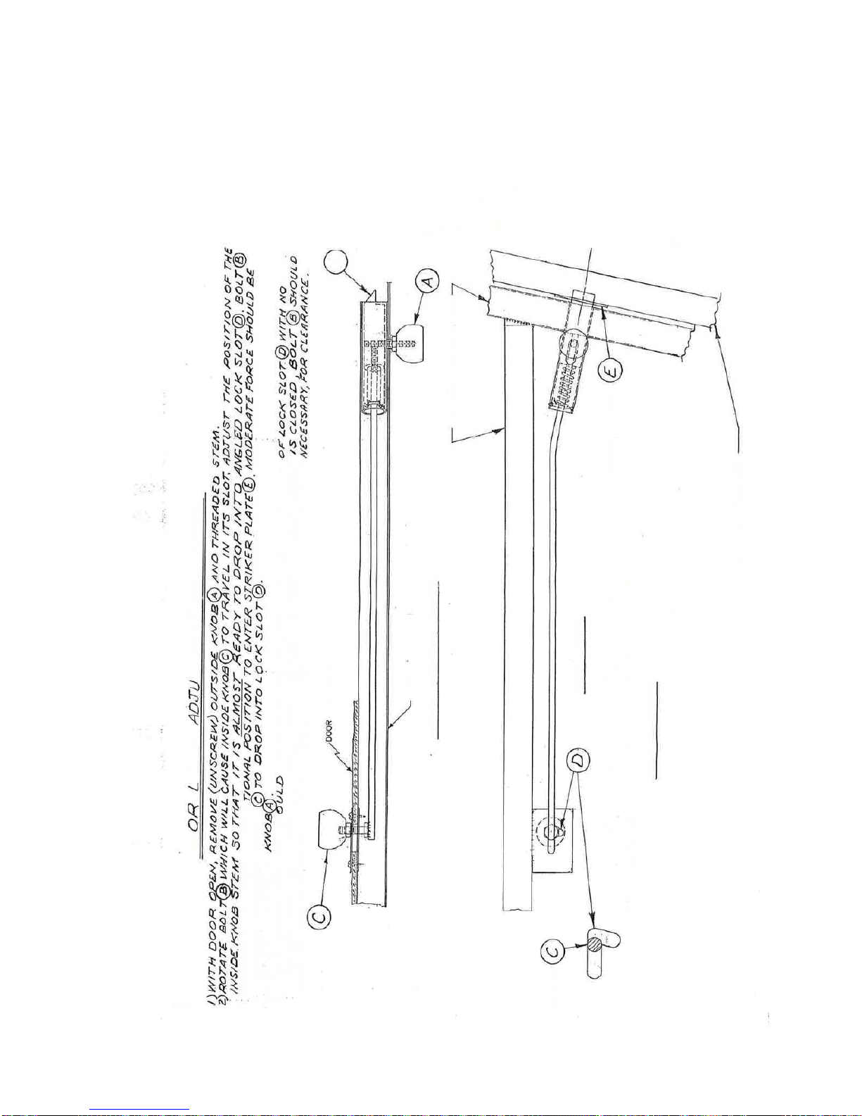
Door Latch Adjustment Procedure....………..........……...… 35
PAGE
Rev. A
Page 4

MAULE AEROSPACE TECHNOLOGY, INC.
MAINTENANCE MANUAL
FOR
MX-7-420
1
LOG OF REVISIONS
Rev.
A
To
Page(s)
3, 19,
23, 24
Description Date
Added oleo strut oil API GL-4 or GL-5 85W-140 gear oil for
new oleo spring P/N 4161B.
04/16/16
Rev. A
Page 5

MAULE AEROSPACE TECHNOLOGY, INC.
MAINTENANCE MANUAL
FOR
MX-7-420
2
SECTION I
GENERAL DATA
GENERAL DESCRIPTION:
Type: Four/five place high wing cabin monoplane.
Engine Installation: Single tractor engine in nose of fuselage.
Wing: Strut braced, two spar, metal covered, modified USA 35-B airfoil. Fiberglass
wing tips.
Fuselage: Welded steel tube structure.
Fuselage and tail group covered with Ceconite synthetic fabric. Fiberglass
engine cowl. Aluminum skin on forward fuselage and doors.
Landing Gear: Main gear split axle type, spring-oil oleo shock absorber. Hydraulic
Brakes. Steerable tailwheel (Automatic locking).
Control Systems: Dual controls wheels, rudder pedals and brakes. All controls direct-
ly cable driven. Fuel control/shut off valve is at the left lower side
panel. Mechanical flap and trim controls are at the center on the
floor. All other controls, switches, etc., are instrument panel
mounted.
DESIGN SPECIFICATIONS:
Wing Span 30 feet 10 inches
Length 24 feet 5 inches
Height 6 feet 4 inches
Gross Weight 2500 lbs.
Empty Weight Approx. 1440 lbs.
Wing Loading 15.8 lbs./sq. ft.
Power Loading 6.8 lbs./BHP
Useful Load Approx. 1060 lbs.
Seats Four/five
Flaps Neg. 7°, 0°, 24°, 40°
Baggage Allowance 250 lb. Structural Limit
Baggage Compartment Dimensions 35½ H x 30W x 21L
Wings: a. Airfoil Modified USA 35-B
b. Chord 63 inches
c. Incidence +30 minutes
d. Dihedral 1.2 degrees
e. Sweepback None
Rev. A
Page 6

MAULE AEROSPACE TECHNOLOGY, INC.
MAINTENANCE MANUAL
FOR
MX-7-420
3
Areas:
a. Wing, Aileron and Flaps 157.9 sq.ft.
b. Ailerons (total) 12.6 sq.ft.
c. Flaps (total) 24.8 sq.ft.
d. Horizontal Stabilizer 18.1 sq. ft.
e. Elevators (including tab) 14.1 sq. ft.
f. Vertical Stabilizer 13.1 sq. ft.
g. Rudder 6.2 sq. ft.
h. Elevator Trim tab 1.03 sq. ft.
i. Rudder Tab .34 sq. ft.
FLUID CAPACITIES AND SPECIFICATIONS:
a. Main Fuel Tanks – (Jet A – wing leading edge inboard)
Right Main Tank 21.5 or 23.8 gallons
Left Main Tank 21.5 or 23.8 gallons
(Main fuel tanks considered one tank.)
b. Auxiliary Fuel Tanks – (Jet A – wing leading edge outboard)
Right Auxiliary Tank 15.0 gallons
Left Auxiliary Tank 15.0 gallons
c. Engine Oil (Mil-L-7808 and later and Mil-23699 and later) 10 quart max.
d. Brakes (Texaco Aircraft Hydraulic Oil 15, MIL-H-5606E or equiv.) 1 pint
e.
Landing Gear - For P/N 4015B oleo spring, use New Holland No.134
hydraulic oil or Ford Tractor No. ESN-M2C134-D. 10W30 engine oil
may also be used. For P/N 4161B oleo spring use API GL-4 or GL-5
85W-140 gear oil
ENGINE FUEL SPECIFICATIONS
Primary MIL -T-5624L, grade JP-4 and JP-5
MIL-T-83133A, grade JP-8
ASTM D-1655, Jet B
ASTM D-1655, Jet A or A1
JP-1 fuel conforming to ASTM D-1655, Jet A
Arctic Diesel Fuel DF-A(VV-F-800B) conforming to ASTM D-1655, Jet A or A1
Diesel #1 fuel conforming to ASTM D-1655, Jet A
CAUTION Not all No. 1 diesel fuels or JP-1 fuels meet the primary fuel specifications. It is
the responsibility of the operator and supplier to determine whether a given fuel
meets these specifications.
Rev. A
Page 7

MAULE AEROSPACE TECHNOLOGY, INC.
MAINTENANCE MANUAL
FOR
MX-7-420
4
Emergency Mil-G-5572F, Aviation Gasoline, all grades (aircraft boost pump on; maximum
of 6 hours operation per overhaul period of turbine through an engine operat-
ing range of idle to 90% maximum SHP.)
CAUTION: MIL-G-5572 fuel containing tricresylphosphate (TCP) additive shall NOT be used.
Cold Weather To assure consistent starts below 4°C (40°F), the following fuels may be
necessary: MIL-T-5624, grade JP-4 ASTM D-1655, Jet B AVGAS/Jet A, Jet
A1, or JP-5 mixture (Refer to Cold Weather Fuels, para 2-48, of Allison 250B17 Engine Series Operation and Maintenance Manual for mixing/use of
cold weather fuel.)
NOTE Jet A, A1, JP-8 or JP-5 fuels are not restricted from use at ambient temperatures below 0°F (-18°C); however, special provisions for starting must be made. (Refer to the Aircraft
Flight Manual.) Prolonged and uninterrupted operation with only AVGAS mixture will induce
lead buildup on turbine parts. This lead buildup can cause a gradual power reduction; consequently, this AVGAS mixture should be used only for cold weather operation. During operation with normal Jet A type fuel, the lead will slowly dissipate.
ENGINE OIL SPECIFICATION
The 250 Series engines are qualified and certified for use with MIL-L-7808 and subsequent,
and MIL-L-23699 series lubricating oils. The vendor brands of MIL-L-7808 and MIL-L-23699
series lubricating oils, which have been engine tested and accepted for use in the Model 250
engine, are listed in the Approved Oils paragraph of Allison 250-BI7 Engine Series Operation
& Maintenance Manual. Refer to para 1-73, Cold Weather Lubrication for the type of oil recommended at specific ambient temperatures.
NOTE Because of availability, reduced coking and better lubricating qualities at higher temperatures, MIL-L-23699 oils are preferred for use in Model 250 engines. (Except for extremely cold weather operation, as indicated below).
Cold Weather Lubrication. The types of oil recommended at specific ambient temperatures
are as follows:
Ambient Temperature. Oil Type
0°C (32°F) and above MIL-L-23699, preferred
0°C (32°F) to -40° (-40°F) NM-L-23699 or MIL-L-7808G
-40°C (-40°F) and below MIL-L-7808G only
Approved Oils: Mixing of approved oils in 250 series engines is permitted only within a given
group number. An oil may be mixed with any other oil in its group. For example, an oil in
Group 23 may be mixed with another brand of oil in Group 23. Refer to the latest revision of
Allison 250-BI7 Engine Operations and Maintenance Manual (Publication 11W2) for approved oils, paragraph 1-74.
WARNING: Mixing of oils within an oil series but not in the same group is permitted only in
an emergency. Use of mixed oils (oils not in the same group) in an engine is limited to five
Rev. A
Page 8

MAULE AEROSPACE TECHNOLOGY, INC.
MAINTENANCE MANUAL
FOR
MX-7-420
5
hours total running time. Adequate maintenance records must be maintained to ensure that
the five-hour limit is not exceeded. Mixing of oils from different series is not permitted. Failure to comply with oil mixing restrictions can result in engine failure.
SECTION II
GENERAL MAINTENANCE
CLEANING AND CARE OF AIRCRAFT
Keeping the performance, speed and durability that was built into your aircraft at the
factory requires more than casual attention. The accumulation of dirt and oil on the outside
and debris inside does affect these factors and can be a fire hazard as well. The first step to
proper maintenance is a clean aircraft.
EXTERIOR
Frequent washing is good for your aircraft finish, especially during the first few
months. Use any quality car wash with a soft cloth or sponge and plenty of clean water-do
not use dishwashing detergent. Drying should be done with a chamois. Accumulation of oil,
grease and exhaust carbon deposits should be removed frequently by using a soft cloth
soaked in mineral spirits or other neutral cleaner.
For general polishing, apply a good quality car polish or wax according to instructions. Clean Plexiglas with plenty of soap and water using grit free soft cloth, chamois or
sponge. Use of a dry cloth on Plexiglas will not only cause scratches but will also build up an
electrostatic field which will attract dust to the surface. Blotting with a clean damp chamois
will remove the charge and the dust. After cleaning, polishing with a good Plexiglas cleaning
product such as "Mirror Glaze" will keep the glass clean and help polish out minor scratches.
Experience has shown that airplanes based at coastal airports or where there is an
otherwise corrosive atmosphere require special treatment to prevent corrosion, specifically
"electrolyte corrosion". Salt water and chemicals act as an electrolyte between dissimilar
metals and can start a strong corrosive action over a short period of time. Maule makes
every effort to separate dissimilar metals with primers and coatings during manufacture, but
there are some locations (such as rivets in wing skins) where this is impossible. To combat
corrosion it is important that the external painted surfaces be kept clean and well waxed.
Wash the airplane with fresh water frequently to remove any salt or chemical film. Periodically, coat the wings, flaps and ailerons internally with a quality corrosion preventative, several of which are available. Floatplanes require more extensive preservation techniques
which are well known in the field.
INTERIOR
Floorboards should be vacuumed frequently and can be cleaned with any good rug
cleaner.
Rev. A
Page 9

MAULE AEROSPACE TECHNOLOGY, INC.
MAINTENANCE MANUAL
FOR
MX-7-420
6
Care should be taken in the disposal of candy wrappers, paper scraps, cigarette
butts, etc. These can work their way under the floorboards and become a fire hazard and
moisture trap.
NOTE: While washing the aircraft, ascertain that all drain holes are open. Clean out
any debris blocking them. Accumulated water can be dangerous, so check behind the baggage compartment frequently.
Textile upholstery may be cleaned using a vacuum cleaner. Grease and oil spots on
the upholstery should be treated with a spot remover or dry cleaning fluid. Do not use soap
and water on textile materials.
Vinyl upholstery may be cleaned using soft whisk broom or suds of any mild soap
(castile or olive oil base) in lukewarm water. Use water sparingly as the upholstery otherwise
requires a long time to dry if water trickles through the seam stitches.
For best results, stains, especially those caused by grease or paint, should be removed from upholstery as soon as possible or they may become “set”" and hard or impossible to remove. "Set" stains should be removed carefully with a clean cloth dampened in denatured alcohol. Stains caused by shoe polish can best be removed with turpentine. However, such cleaning agents are liable to affect the dust-repellent finish of the vinyl if used in
excess of the actual requirements. Never use volatile solvents such as lacquer thinner, acetone, etc. on upholstery.
The cleaning should be completed by wiping the surface of the vinyl dry with a clean
cloth, particularly in the seam. No attempt should be made to apply preservatives such as
wax, polish, or varnishes, as these will not be absorbed by vinyl, but will merely collect dust.
There are protective treatments made especially for vinyl which are commercially available
and quite satisfactory.
Leather upholstery should be cleaned by leather cleaning methods using leathercleaning products.
Rev. A
Page 10

MAULE AEROSPACE TECHNOLOGY, INC.
MAINTENANCE MANUAL
FOR
MX-7-420
7
INSPECTION GUIDES
AIRFRAME INSPECTION
At 25 Hour Total Time, perform 50 Hour Inspection as described below:
At 50 Hour Total Time and every 50 hours thereafter:
1. Check battery for general condition and electrolyte level.
2. Check all main electrical connections.
3. Check fluid level in brake reservoirs.
4. Check the entire fuselage, tail surfaces and wing skins for cracks, security of fair-
ings and general condition.
CAUTION: If airplane is subject to excessive stress, i.e., heavy loads, adverse wind
conditions, rough landings, etc., take special care in examining wing skins for any
cracks. If any are found, repair before further flight in accordance with AC 43:13 and
factory drawings. (Do not replace any countersunk rivets with buttonhead rivets in wing
because it is not approved.)
5. Check aileron and flap skins for cracks.
6. Check the security, operation and general condition of all control surfaces.
7. Check main landing gear for condition and brakes for leakage and wear.
8. Check main landing gear oleo struts for oil leaks.
9. Check general condition of tailwheel, leaf springs and spring attachment. Leaf
springs should have 45° angle with no weight on the wheel. Check all bolts and
nuts holding the tail springs to the fuselage. Tighten nuts, if needed, so that there
is no play or side movement in the springs or their attachment.
10. Check tires for inflation and cuts.
11. Drain sumps of fuel tanks, checking for contamination and water.
At 100 Hours Total Time and every 100 Hours thereafter, perform the 50 hour inspection
plus the following:
1. Remove right and left kick panels in cockpit, windshield side post covers and panels
below seat fronts. Examine protective rudder cable guide tubes, (located behind
kick panels), if installed and attaching clamps, bolts and nuts for security and general condition.
Rev. A
Page 11

MAULE AEROSPACE TECHNOLOGY, INC.
MAINTENANCE MANUAL
FOR
MX-7-420
8
2. Examine all front cockpit electrical connections and wires, fuel lines and fittings,
control cables attachments and pulleys for security, leaks, chafing, etc.
3. Remove rear seat, rear floorboard and panel behind baggage compartment.
4. Inspect all structure, all control cables, pulleys, fairings and electrical connections
and wires for security, chafing and corrosion.
5. Open zippers in headliner and inspect all control cables, pulleys, fairleads and electrical connections and wires for security and chafing.
6. Remove wing root fairings and inspect control cables, fairleads, fuel lines and connections, and electrical wires and connections for security, chafing and leaks. Inspect wing attach points for security and corrosion.
7. Remove wing strut fairings, top and bottom, and inspect attaching fittings and bolts
for security, corrosion and cracks. Carefully inspect both sides of lift struts for abrasion, corrosion, pin holes and punctures. Any paint loss or minor corrosion
should be sanded down to bare metal with fine sandpaper and metal primer should
be applied. After the primer is dried, a finish coat of the desired color may be added. Powder coating is recommended if complete strut is being refinished.
WARNING: Any unrepairable dents or punctures in strut are cause for replacement of
the strut.
CAUTION: This aircraft was equipped with sealed struts when manufactured, however,
if these struts were replaced in field with unsealed struts, comply with Maule Service
Bulletin No. 11 (AD# 98-15-18) as required. (New sealed struts are identified by two
weld spots located at upper end. Removal of the upper cuff is needed to locate the
weld spots).
CAUTION: Item (a)(4) of AD# 98-15-18 is very misleading as Maule never drills holes
in struts to attach cuffs, door clips or any hardware and it is illegal to do so since there
are no approved holes in the wing struts under the TC data. If aircraft has a modification added requiring a drilled hole in strut under a #337, refer to AD for inspection requirements at the 24-month intervals. Also, inspect the area around the holes(s) frequently for corrosion or cracking (ref. SL#58).
8. Remove wheels and inspect wheels, tires, brake disc, bearings, brake lines and
brake pad for wear, cuts, chafing, leaks and general condition. Repack wheel bearings.
9. Remove landing gear top fairings and inspect attaching fittings and bolts for security, corrosion and cracks and inspect brake hose for security, chafing and leaks.
10. Remove all inspection covers/plates and inspect all visible control cables, pulleys,
bellcranks, electrical wires and connections, fuel lines and fittings, nuts, bolts, etc.
for security, chafing, leaks, etc.
Rev. A
Page 12

MAULE AEROSPACE TECHNOLOGY, INC.
MAINTENANCE MANUAL
FOR
MX-7-420
9
(CAUTION: If a wing has been removed and reinstalled, or a new wing installed, visually inspect the routing of aileron cables through the inspection hole cover located on underside of wing, aft of rear spar and outboard of wing strut attach brackets. Ascertain
that cables are not routed over the strut attach brackets and are properly routed
through the fairleads and around pulleys. Ref. Maule Service Bulletin No. 12.)
11. CAUTION: At inspection hole in tail, visually check the pivoting action at the control
cable attachment points over the full range of rudder and elevator travel. This action should be such that there are no bending loads imparted to the turnbuckles
(which are designed for straight tension load only). Any binding, which causes
bending of the turnbuckles, should be removed. Any cable attachment parts, which
display appreciable corrosion, must be replaced before further flight. NOTE: Pivot
points must be cleaned and lubricated with any lightweight lubricating oil. Following
lubrication, the cable attachments, including the turnbuckles, must be heavily
coated with a good preservative such as :
Black Bear Paralketone Preventative LPS 3, Heavy Duty Rust Inhibitor
Black Bear Co. (preferred) LPS Laboratories, Inc.
Long Island City, NY Tucker, GA
NOTE: Maule Service Bulletin No. 9 covers corrosive resistant parts replacement and is
particularly recommended for airplanes operating in a potentially corrosive environment.
Compliance to this SB provides for larger stainless steel turnbuckles and corrosion resistant steel fasteners and attachment details for the elevator cables.
12. CAUTION: Special attention should be given to the horizontal stabilizer strut lower
attach tubes which are welded to the lower longerons. The seal on the inside of the
lower strut attach stub tubes can deteriorate with age which could cause corrosion
on the interior of the attach stub tubes, especially on floatplane models. It is recommended that the stabilizer struts be removed to inspect attach stub tubes at
each annual. If there is visible external corrosion around the attach stub tubes, or
the internal seal appears loose or cracked, remove the seal, clean the inside of the
tube and visually inspect the inside for corrosion. If corrosion is found, repair in accordance with AC 43.13-1B. After repair, or if no corrosion is found, fill entire tube
with silicone rubber to seal tube from moisture. Inspect the struts for dents, corrosion, or punctures and replace if necessary. Reinstall struts with new hardware and
document in aircraft records.
13. Lubricate all chains and points of rotation on sprockets, pulleys and bellcranks.
14. Inspect and lubricate all control surface hinges and control horn connections.
15. Lubricate door hinges and latches and seat tracks.
CAUTION: Carefully inspect all door hinge bolts and nuts for condition and security. If
using elastic nuts on door hinges, they must be replaced with castle nuts and cotter
pins. Refer to Maule Service Letter No. 61.
Rev. A
Page 13
MAULE AEROSPACE TECHNOLOGY, INC.
MAINTENANCE MANUAL
FOR
MX-7-420
10
16. Lubricate rudder pedals and rudder bar points of rotation.
17. Check control rigging and cable tensions.
18. Check and clean vacuum system regulator valve filter and intake filter.
19. Check the pitot static system for leaks.
20. Ensure that all applicable Airworthiness Directives and Maule Service Letters and
Bulletins that are mandatory have been complied with.
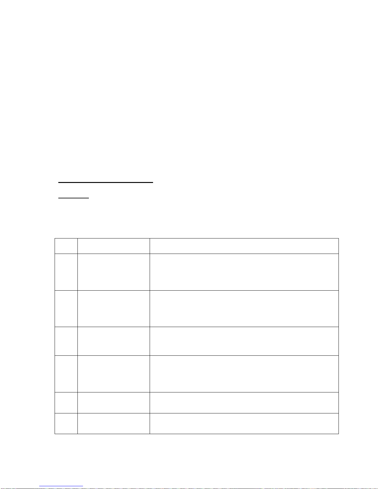
ENGINE INSPECTION
Scheduled Engine Inspection
CAUTION: Before undertaking any inspection or maintenance action, consult the referenced
paragraphs of the Allison Operation and Maintenance Manual. Failure to do so could result
in equipment damage or destruction, possibly resulting in personnel death or injury.
100 HOUR INSPECTION
Item Reference Inspection/Maintenance Action
Inspect the engine for loose or missing bolts, broken or
1 N/A
loose connections, security of mounting accessories and
broken or missing lock wire. Check accessible areas for obvious damage and evidence of fuel or oil leakage.
Check mounting and support bolts to be sure they are tight,
2 N/A
lockwired and in good condition. Check security of screws
and rivets. Remove all foreign materials which might be
drawn into the compressor inlet.
Check accessible fuel system components, lines, and con-
3 N/A
nections for security, damage or leakage. Accomplish with
the boost pump on.
Check fuel and propeller system control linkage for freedom
4 3-134
of operation, full travel and proper rigging. Check for excessively high throttle forces and security of linkage. Also
check for loose or worn linkage and linkage bolts.
5 N/A
6 3-37
Inspect compressor inlet guide vanes and visible blades and
vanes for foreign object damage.
Clean compressor with chemical wash solution if operating
in a smoggy area (as required).
Rev. A
Page 14
MAULE AEROSPACE TECHNOLOGY, INC.
MAINTENANCE MANUAL
FOR
MX-7-420
11
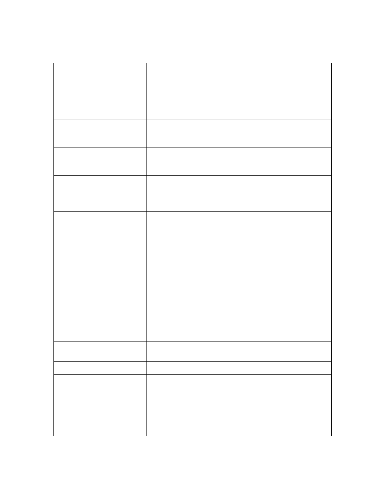
Inspect the compressor scroll for cracks or breaks at the
7 N/A
anti-ice valve and customer bleed ports. If cracks or breaks
are detected, check engine for possible vibration causes.
Inspect for discharge air tube inserts that are cocked or
8 N/A
backing out of the scroll. If cocked or loose inserts are detected, check engine for possible vibration causes.
Check anti-icing valve for security, worn parts and proper
9 3-193
operation. Valve need not be removed or disassembled unless a problem is detected.
Inspect compressor mount inserts for looseness or oil lea-
10 3-237, 3-238
kage. Replace if loose and check engine for possible vibration causes.
Inspect the turbine support assemblies and engine exhaust
11 3-221
ducts for condition of welded joints, for cracks and buckling.
Check exhaust duct clamps for proper installation, condition
and torque.
Wet spline starter-generator gearshafts (new production or
those replaced in accordance with the Allison Commercial
Engine Bulletin (250-B17TP CEB-1056) do not need periodic inspection and lubrication. Clean and inspect any other
starter-generator gearshaft. Clean the female splines of the
starter-generator with mineral spirits and a soft brush. Inspect splines in accordance with para 3-236, Starter-
12 3-235
Generator Gearshaft Female Spline Inspection.
Lubricate acceptable splines with grease (Aeroshell No.22,
or equivalent). Before reinstallation of the starter-generator,
make sure torsional damper members of the startergenerator driveshaft are in hard contact with each other.
NOTE: Inspect the starter-generator brushes for wear in accordance with the Aircraft Manual at the same time the
spline inspection is made.
13 Item 5, Table III-10
Inspect and clean the turbine pressure oil system check
valve.
14 Item 4, Table III-10 Inspect and clean pressure oil tube screen assembly.
15 3-178
Measure oil flow from the scavenge passage or external
sump of the power turbine support.
16 Item 7, Table III-10 Inspect, clean and check magnetic drain plugs.
17 3-230
Rev. A
Inspect the outer combustion case for condition. Inspect the
weld joints of cases that do not have the brazed screen reinforcement in the armpit area.
Page 15
MAULE AEROSPACE TECHNOLOGY, INC.
MAINTENANCE MANUAL
FOR
MX-7-420
12
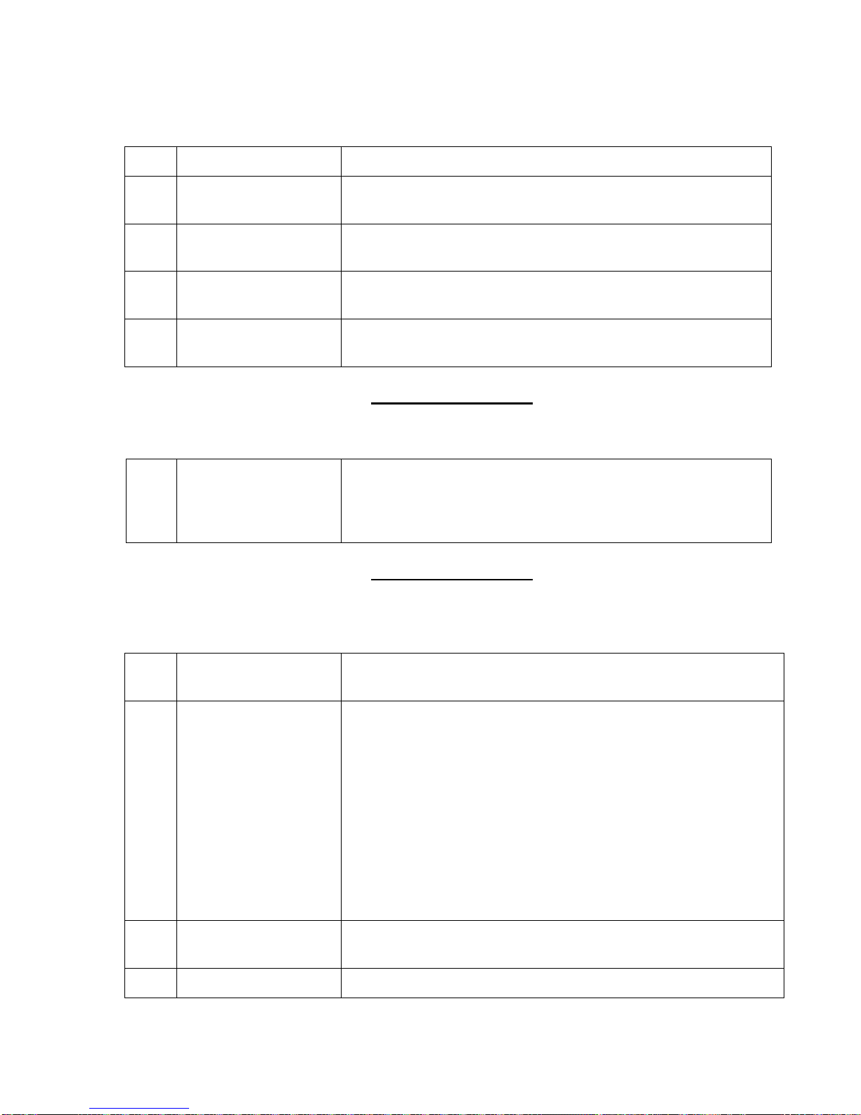
18 3-232 Clean the burner drain valve.
19 3-185
20 N/A
21 N/A
22 N/A
Inspect the ignition lead for burning, chafing, or cracking of
conduit and loose connectors and broken lock wire.
Review engine records for compliance with all mandatory
bulletins, inspections and airworthiness directives.
Review engine records for time or cycle limited parts, components, accessories or modules.
Enter component changes, inspection compliance, etc., in
logbook as required.
200 Hour Inspection
ln addition to the l00 hour inspection items, perform the following:
23
Item 1, Table III-103168; Item 2, Table III10 3-163, 3-172; Item
Drain oil system and refill; remove, clean and reinstall the oil
filter and magnetic drain plugs.
7, Table III-I0
300 Hour Inspection
In addition to the 100 hour and appropriate 200 hour inspection items, perform the following:
Rev. A
24 3-83
Inspect the compressor case when operating in an erosive
environment.
If the aircraft is equipped with an engine fuel filter differential
pressure warning system, replace the throw-away filter only
when an indication of contamination is obtained or every 300
hours, whichever comes first. If the aircraft is not equipped
with a differential pressure warning system, replace the fuel
25 3-117
filter every 300 hours unless operating experience demonstrates that smaller time increments are advisable.
CAUTION: When there is evidence that the fuel pump filter
has been bypassed, the gas producer fuel control filter assembly must be cleaned. (Refer to Cleaning the Gas Producer Fuel Control Fuel Strainer, para 3-113.)
26 3-121
Perform a fuel pump bypass valve operational check whenever a fuel filter is replaced.
27 3-105 Purge air from the filter bowl area of the single element pump.
Page 16
MAULE AEROSPACE TECHNOLOGY, INC.
MAINTENANCE MANUAL
FOR
MX-7-420
13
28 3-108 Inspect and clean the fuel nozzle.
29 Item 8, Table III-10 Inspect and clean the No. 1 bearing oil pressure reducer.
30 Item 11, Table III-10
31
3-166 Item 10,
Table III-10
Visually inspect external sump. Clean internal carbonaceous
deposits from sump.
Inspect the power turbine support scavenge strut. Clean internal carbonaceous deposits from sump.
Other Scheduled Inspections
Interval Reference Inspection/Maintenance Action
Inspect uncoated and coated power turbine outer coupling nuts
for corrosion. Compliance with bulletins removes this requirement.
500HR/1 YR
250-B 17
CSL-1030
Check the fuel pump driveshaft on Sundstrand single element
500 HR 3-120
pumps for spline wear. NOTE: This inspection not required on
TRW pumps.
600 HR 3-89
Make an installation rotating balance of the engine and propeller at intervals not to exceed 600 hours.
1500 HR 3-128 Replace fuel control strainer assembly.
Inspect the compressor case. Inspection frequency shall be
1750 HR 3-83
made as necessary by operating environment. In erosive environment, inspect case at least every 300 hours. In any environment, do not exceed 1750 hours without case inspection.
1750 HR 3-212A
Engine Oil System Scheduled Maintenance
(Table III-10 from Allison Operations & Maintenance Manual)
No. Item Action Time Period Notes
Engine
1
lube oil
Change oil
Inspect and clean filter
2
Engine oil
filter
element using ultrasonic
cleaner with perchloroethylene.
Rev. A
Inspect the compressor splined adapter internal splines and the
spur adapter gearshaft splines (forward and aft) for wear.
200 hr max,
or six months,
whichever
comes first
100 hr max.
Follow procedures in Oil
Change, para 3-163. (Refer
to Approved Oils, para 1-
74.)
Follow procedures in Oil Filter, para 3-168.
Page 17

MAULE AEROSPACE TECHNOLOGY, INC.
port
MAINTENANCE MANUAL
FOR
MX-7-420
14
Engine
3
lube oil
Pressure
oil tube
4
screen assembly
Turbine
pressure
5
Oil System
Check
Valve
Oil flow
from P.T.
scavenge
passage or
6
external
sump and
G.P scavenge passage
When changing from
MIL-L-7808 to MIL-L-
As necessary
23699 or vice versa
Inspect and clean screen
using mineral spirits
100 hr max.
Inspect and clean 100 hr max.
Measure oil flow 100 hr max.
Refer to Approved Oils, para
1-74.
Refer to applicable part of
Cleaning the Power Turbine
Support Pressure Oil Nozzle, para -3-177.
Oil system check valve para
3-170.
Follow procedures in Oil
Flow Measurement, para 3-
178.
7
8
9
10
Magnetic
drain plugs
No. 1 bearing oil
pressure
No. 6-7
and No. 8
bearing
pressure
oil nozzle
Power turbine sup
scavenge
oil strut
Inspect and clean 100 hr max.
Inspect and clean 300 hr max.
When neces-
Inspect, clean internal
carbonaceous deposits.
sary, as directed by the
oil flow measurement
Inspect and clean internal carbonaceous depo-
300 hr max.
sits.
Follow procedures in Magnetic Plug, para1-172.
Follow procedures in Oil
Change, para 3-163
Refer to oil flow measurement, para 3-178. If an oil
flow of less than 90 cc is observed from the P.T. scavenge passage or 75 cc
from the G.P. scavenge
passage, follow procedures
in Gas Producer and Power
Turbine Pressure Oil Manifold, para 3-165 and inspection and Cleaning of Power
Turbine Support Scavenge
Oil Strut, para 3.166.
Follow procedures in Inspection and Cleaning of Power
Turbine Support Scavenge
Oil Strut, para 3-166.
Rev. A
Page 18
MAULE AEROSPACE TECHNOLOGY, INC.
MAINTENANCE MANUAL
FOR
MX-7-420
15
Visually inspect for internal carbonaceous deposits.
300 hr max.
Clean or replace sump as
required.
11
External
sump
SPECIAL ENGINE INSPECTIONS
Special inspections are required when the engine has been subjected to abnormal operating
conditions, when engine damage is suspected, or when associated parts are removed from
the engine. The special occurrence, the component or system to be inspected, and the nature of the inspection are given in Table III-11, Allison Operating and Maintenance Manual.
SUDDEN STOPPAGE INSPECTION
The following inspections must be satisfactorily completed whenever the propeller strikes a
moving or stationary object.
NOTE: Sudden stoppage is the momentary or complete interruption in the rotation of the
aircraft propeller and engine drive system when the aircraft propeller comes in contact with
the ground, water, trees, or other obstacles.
The shock felt by the drive system requires that the engine be inspected and/or overhauled
by a designated overhaul facility as a result of possible damage.
If the aircraft propeller strikes an object causing damage to the propeller which can be corrected by light grinding or filing and normal blending of the blades (nicks, gouges, scratches,
etc.) in accordance with applicable propeller service instructions, complete the following inspection:
Rev. A
a Inspect the engine inlet for foreign objects.
b Inspect the compressor blades and vanes for foreign object damage.
c Inspect the compressor case for evidence of blade tip rub.
d
e
Inspect all magnetic plugs for metal accumulation. (Refer to Magnetic Plug, para 3-172 and Table III-14.)
Rotate the propeller by hand and check for unusual noise.
f Motor the engine and check for unusual noise.
g
Operate the engine for 30 minutes on the ground then check the magnetic plugs
for metal accumulation.
h Check balance the propeller.
Page 19
MAULE AEROSPACE TECHNOLOGY, INC.
MAINTENANCE MANUAL
FOR
MX-7-420
16
If the aircraft propeller strikes an object causing damage to the propeller blades requiring
blade replacement and overhaul of the propeller assembly, remove the engine and send it to
a designated overhaul facility for inspection.
a Refer to the appropriate propeller Service Instructions and Overhaul Manual.
b
Refer to the Special Inspections required after propeller strike and/or crash in
the engine Overhaul Manual.
HARD LANDING LIMITS.
Make a visual inspection of the installed engine for external damage from airframe components after any hard landing. Engines that have sustained landing forces exceeding 10g
shall be sent to an overhaul facility.
COMPRESSOR INLET AIR BLOCKAGE.
Replace the compressor assembly if the engine has been operated with inlet air restricted
due to foreign objects or materials which have become lodged in the compressor inlets. Tag
the replaced compressor to show that the cause of removal was inlet air blockage. Conditions which constitute blockage are as follows:
Foreign objects or materials found in the inlet during inspection of the aircraft
a
when not in operation. If it can be determined that the blockage was not there
during the last operation of the engine, remove the foreign object or material
and leave the compressor in service.
Power loss encountered following a restriction at the compressor inlet area
while the engine is in operation. Blockage in flight can usually be verified by
inspection after landing (blockage still exists). However, some blockage may
b
be followed by ingestion before inspection can take place. Objects or materials which were large enough to have stopped at the inlet guide vanes before
ingestion, or which cause a noticeable raise in TOT, can be considered to have
caused compressor inlet blockage.
Rev. A
Page 20

MAULE AEROSPACE TECHNOLOGY, INC.
MAINTENANCE MANUAL
FOR
MX-7-420
17
RIGGING PROCEDURES
1. LEVELING:
Laterally: The airplane can be accurately leveled laterally using the front spar attach
bolts. Turn these two bolts so that a flat on the head is "up". Fabricate two
equal length spacers (1½ inch minimum length) which can be placed on the
bolt heads. Place a 48 inch level across the two spacers and block under the
landing gear to center the bubble.
Longitudinally: Using a level thirty-six (36) inches long or longer, place it on the leveling
lug and leveling mark thirty-one (31) inches to the rear of the leveling lug
on the bottom of the right wing root. Raise the tail to bring bubble to center.
2. DIHEDRAL ANGLE:
To check dihedral angle at the front spar, remove both top wing root fairings to expose the front spar attach bolts. Stretch a string along the top of the wing above the
front spar, from wingtip to wingtip, and draw it tight. The end of the string can be attached to tie down fittings underneath the wing to hold tautness. Be careful to protect the
edges of the wingtips from string chafing.
Find the row of flush rivets on the top of each wing from wingtip to wingtip at the front
spar location. Measure from the forward wing to fuselage attach bolt centerline, for both
left and right wings, outboard 127.5 inches along the top of each front wing spar. Using
masking tape or equivalent, tape the string down on the rivet centerline at this point.
At the inboard end of the front spar, measure the distance from the top rear edge of
the spar cap to the string on both wings. Adjust the front wing struts so as to have a
measurement of 2 3/4 inches on each wing (plus or minus 1/8 inch) at this location. It is
recommended that the rear struts be removed while adjusting dihedral. The wing must
be supported while the front strut is being adjusted. For rear strut adjustment, see section on Washout.
CAUTION: Be sure that the strut fork is not extended more than 1 inch of threads from
the strut end to the end of the fork threads (not including the jam nut). There must be at
least 1 3/8 inch of thread engagement into the strut.
3. WASHOUT:
To adjust the washout in the wings, proceed as follows:
Put a leveling protractor chordwise on the underside of the wing root and adjust it to
a zero degree reading. Now put the protractor chordwise just inboard of the wing tip
and adjust the rear strut to give ½° trailing edge up, difference from the wing root angle.
Rev. A
Page 21

MAULE AEROSPACE TECHNOLOGY, INC.
MAINTENANCE MANUAL
FOR
MX-7-420
18
4. TAIL ASSEMBLY:
With the airplane in level position, the stabilizers should be leveled at their rear spars.
The hinge line should be straight from tip to tip. The vertical stabilizer should be plumb at
the hinge.
5. AILERONS:
Adjust the ailerons to streamline position by placing a straight edge on the bottom of
the wing chordwise at the inboard end of the aileron. Then adjust the turnbuckles in the
aileron system so the control wheels are centered and there is a gap of zero to ¼ inch
between the straight edge and the trailing edge of the aileron.
Check the aileron travel for 20° ±1° up and 20° ±1° down. Adjust turnbuckles to stay
within these limits. Proper cable tension is 15 to 25 lbs.
6. FLAPS:
Adjust the first notch flap position to be aligned with the aileron trailing edge with the
ailerons centered. Check the flap travel with flap handle at fully retracted (handle down)
position for negative 7° ±1° up, and 24° ±3° down for second notch, and 40° ±3° down for
third notch. Adjustment, if needed, may be accomplished by adjusting turnbuckles located above front seats through headliner.
7. RUDDER:
Check the rudder travel for 21° ±1° right and left. Rudder cable tension is controlled
by springs, and the cables should not be slack with the rudder centered. Rudder trim
may be accomplished by adjusting the tension of the rudder centering springs located
behind the rear bulkhead. Keep springs as short as possible but never less than 4½
inches from end coil to end coil with the rudder centered.
8. ELEVATORS:
Elevator control movements are up 30° ±1°, down 20° ±1°. Stops are located on the
vertical tail rear spar just inside the inspection plate. Proper cable tension is 25 to 45 lbs.
Elevator down spring tension is 5 lb., + 1 lb. minus 0 lb. average load measured at trailing edge.
9. ELEVATOR TRIM:
Elevator trim tab movement is 12° ± 2° up, 38° ± 2° down. If adjustment is needed, it
may be done at the turnbuckles located just aft of the trim control. Proper cable tension
is 15 to 25 lbs.
Rev. A
Page 22

MAULE AEROSPACE TECHNOLOGY, INC.
MAINTENANCE MANUAL
FOR
MX-7-420
19
10. RUDDER TAB:
This tab is interconnected with the aileron system to automatically coordinate rudder
with aileron to reduce adverse yaw. The tab should normally be streamlined with the
rudder when the aileron and rudder controls are centered.
The tab may be used to adjust rudder trim. In normal cruise, it is desirable to have
the ball centered with the “Rudder Trim” control out to first line. This allows for inflight
adjustment of rudder trim in cruise. Rudder trim may be adjusted by changing the position of the tab cables located just over the front doors on the inside of the airplane.
The tab travel is 48° ±4° right or left. Proper cable tension is 5 to 10 lbs.
CAUTION: Make sure tab is free at extreme aileron travel.
NOTE: The “Rudder Trim Control” on the instrument panel pulls on a spring attached
to the right rudder pedal. It is not connected to the tab on the rudder.
LUBRICATION
1. Main wheel bearings - Use good quality wheel bearing grease.
2. Oleo shock struts – For P/N 4015B oleo spring, use New Holland No.134 hydraulic oil or
Ford Tractor No. ESN-M2C134-D. 10W30 engine oil may also be used. For P/N 4161B
oleo spring use API GL-4 or GL-5 85W-140 gear oil.
3. Landing gear hinges – Use engine oil.
4. Control Column - Apply light coat of graphite base lubricant to aileron balance chain, torque tube and control guide. Use lightweight lubricating oil on all other bearings.
5. Control pulley bearings and control surface hinges - Use lightweight lubricating oil.
6. Flap bellcrank and mechanism - Use lightweight lubrication oil.
7. Aileron and flap hinge - Use lightweight lubricating oil.
8. Elevator and trim tab - Use lightweight lubricating oil.
9. Tailwheel - Good quality wheel bearing grease to tailwheel bearings through zerk fitting.
Same for fork spindle roller bearings, if necessary. See tailwheel maintenance section
under "Landing Gear, Wheels and Brakes".
Rev. A
Page 23

MAULE AEROSPACE TECHNOLOGY, INC.
MAINTENANCE MANUAL
FOR
MX-7-420
20
FABRIC REPAIRS:
(Applicable to Polyurethane paint on Ceconite fabric only)
REPAIRS:
1. Small holes and damaged areas can easily be repaired without removing the existing
paint topcoat.
2. Trim the damaged area to a rectangular or circular shape.
3. Lightly scuff sand with #320 or #400 wet/dry sandpaper approximately 2 inches around
the repair area.
4. Mix one part gray urethane primer (catalyst) with two (2) parts gray urethane primer (2:1
ratio - 2 parts paint/1 part catalyst), mixing a very small amount only for coating the
sanded area around the repair.
5. Apply one coat (this may be brushed) to the sanded area slightly larger than the size of
the patch to be applied. This application aids in total adhesion to the topcoat and offers a
fresh chemical adhesion base for the repair patch.
6. Allow prime to dry for 4 hours.
7. Apply a coat of urethane adhesive (thinned one to one (1:1) with urethane adhesive thinner by volume) to the primed area slightly larger than the repair patch size. Allow this to
dry for approximately 15 minutes.
8. Apply a second coat of the thinned urethane adhesive and lay the patch in the wet bed of
adhesive, smoothing the edges while applying a topcoat of the thinned urethane adhesive, working he edges down. Allow to dry at least 8 hours prior to any shrinkage.
SHRINKING THE REPAIR AREA:
1. When using an iron to shrink the patch, always use a piece of aluminum foil over the
area to be tautened and the surrounding undamaged topcoat. This is to prevent any
scorching of the topcoat. Follow the procedure previously mentioned (primer and finish
coat application). Take care to feather sand as required during primer procedure to
feather the repair patch and blend in prior to topcoat spraying.
SPECIAL PRECAUTIONS:
1. For any repair or damaged area, refer to FAA AC 43.13 1B. Only use equal or next
heavier weight fabric for repair patch. Do not substitute any other products or brands in
this procedure
Rev. A
Page 24

MAULE AEROSPACE TECHNOLOGY, INC.
MAINTENANCE MANUAL
FOR
MX-7-420
21
SECTION III
MAJOR COMPONENT PARTS
WINGS:
The complete wing is of metal construction (2024-T3 aluminum) with a fiberglass wing
tip.
Spar root end strut fittings are made of 2024-T4 aluminum.
LIFT STRUTS:
The lift struts are streamlined tubes attached to the wing and fuselage by means of AN
standard steel bolts. When inspecting the struts, check for nicks and dents and see that all
bolts are snug (not tight).
In handling the airplane on the ground, care should be take to prevent damage to the lift
struts by pushing or lifting in the middle of the strut. Frequent inspection of the struts should
be made and any paint loss or minor corrosion should be sanded down to bare metal with
fine sandpaper and metal primer should be applied. After the primer is dried, a finish coat of
the desired color may be added.
WARNING: Any unrepairable dents or punctures are cause for replacement of the strut.
(See also page 8, item 7.)
FUSELAGE:
The fuselage is a welded truss type structure having an integral vertical tail fin. Chrome
molybdenum steel (4130) is used for all tube members, control fittings, floor supports and
seat members. Door frames and other nonstructural parts are made of cold rolled steel
(1008 to 1015) or stainless steel (per customer’s request).
If it becomes necessary to replace any fuselage members, sleeve type splices should
be made in accordance with practices outlined in FAA AC 43.13-1, Aircraft Inspection and
Repair.
The forward fuselage section is aluminum covered (2024-T3). The firewall is made of
.018 galvanized sheet steel or stainless steel.
The aft fuselage section is covered with Ceconite fabric and standard dope and paint
finish as per Maule Specification S-17. This fabric need not be pulled or punch tested.
Rev. A
Page 25

MAULE AEROSPACE TECHNOLOGY, INC.
MAINTENANCE MANUAL
FOR
MX-7-420
22
SURFACES AND CONTROL
AILERONS AND FLAPS:
The ailerons and flaps are aluminum alloy structures covered with 2024-T3.
The aileron control system consists of a chain drive connecting the two control wheels
and is attached to the necessary cables which are routed over pulleys through the fuselage
and into the wing section to the aileron horns.
The flap control system consists of a control lever which has four active positions, (-7°,
0°, 24°, 40°). This is connected to the control cables (and spring cartridge located directly
behind cargo area) which are routed over pulleys through fuselage and connected to chain
drive located directly above the cabin area. This chain drive is connected to a torque tube
which operates the flap through a push-pull rod attached to the inboard hinge fittings.
ELEVATORS:
The elevator has chrome molybdenum (4130) internal structure covered with Ceconite
fabric. Inspect for corrosion. Drain grommets should be kept open. The hinge attachments
should be lubricated with light engine oil. Accumulations of dust and dirt on hinges should be
removed.
STABILIZERS:
The stabilizers have chrome molybdenum steel (4130) internal structures covered with
Ceconite fabric. Inspect for corrosion including elevator hinges and struts.
RUDDER:
The rudder structure is very similar to the elevators. No maintenance other than inspection for corrosion is needed. The hinges should be cleaned and lubricated with light engine
oil at frequent intervals. The cable attachment points should be checked for wear and corrosion.
TRIM AND RUDDER TABS:
These surfaces have low carbon steel frames with aluminum alloy skin (2024-T3).
These surfaces need no maintenance other than inspection for corrosion. The hinges
should be lubricated at frequent intervals using light engine oil.
Rev. A
Page 26

MAULE AEROSPACE TECHNOLOGY, INC.
MAINTENANCE MANUAL
FOR
MX-7-420
23
LANDING GEAR, WHEELS AND BRAKES
MAIN LANDING GEAR:
MAIN LANDING GEAR:
TOE-IN:
If ground handling of the airplane makes toe-in suspect, inspect main landing gear as follows:
1. With airplane unloaded, jack-up airplane on one side and spin tire. If center groove runs true, do
same on other side. If not, mark tire, or both tires as needed, while spinning with black marker
pen.
2. Support tail to level (flight attitude) with main tires on floor. Measure from the floor to centerline of
axle and using that dimension, measure up from floor on front of tire in center and on back of tire
and mark. Do same on other side.
3. Measure between grooves and/or mark(s) at height marks, across front and then rear. The difference should be 0” to 1/4” toe-in for 7:00 tires and 0” to 3/8” toe-in for 8:50 tires.
LANDING GEAR SHOCK ABSORBER:
This gear is supported by two spring oil type oleo struts which must be full of oil at all times. The oil may
be checked by removing a 1/8” pipe plug at the top end of the strut. If oil is needed for P/N 4015B oleo
spring, use New Holland No.134 hydraulic oil or Ford Tractor No. ESN-M2C134-D. 10W30 engine oil
may also be used. For P/N 4161B oleo spring use API GL-4 or GL-5 85W-140 gear oil.
DISASSEMBLY OF OLEO STRUT:
1. To remove the strut, the weight must be taken off of the gear. The bolt at the top and bottom can
then be removed, freeing the strut. Higher strength top bolts are available to eliminate bending
from hard landings.
2. Remove four (4) bolts at top of strut.
3. Remove oil filter plug.
4. Pull out cylinder head and spring assembly.
5. To remove spring, take all nuts off of strut shaft and press piston upward to free bolts for removal.
Remove bolts, and piston will come out of end of shaft.
6. Replace worn parts, weak spring, etc. New replacement springs are stronger than the original
springs. The “O” ring on the strut shaft and on the cylinder head should be replaced at this time
also.
Rev. A
Page 27

MAULE AEROSPACE TECHNOLOGY, INC.
MAINTENANCE MANUAL
FOR
MX-7-420
24
ASSEMBLY OF OLEO STRUT:
1. Reassembly is the reverse of steps 5 and 6.
2. Fill cylinder 1/2 full of New Holland No.134 hydraulic oil or Ford Tractor No. ESN-M2C134-D for
P/N 4015B oleo spring. 10W30 engine oil may also be used. For P/N 4161B oleo spring use API
GL-4 or GL-5 85W-140 gear oil.
3. Align cylinder head bolt holes with cylinder bolt holes and insert spring assembly.
4. Install cylinder head bolts, filler plug and safety.
5. Reinstall strut on airplane being careful to get the spacers in at the top attaching bolt.
6. Work airplane up and down on strut and check for oil leaks.
7. Recheck and fill to top.
LANDING GEAR LEGS AND AXLE:
The landing gear is made of chrome molybdenum steel (4130) and has an aluminum skin (2024-
T3).
These need no maintenance other than inspection for corrosion. The hinges should be lubricated
every hundred hours using a light engine oil.
MAIN WHEELS AND BRAKES:
See Equipment Lists for items installed and options.
To change a tire, follow these steps:
1. Chock opposite main wheel and tailwheel.
2. Raise wheel with a light scissors jack or a small bottle jack placed about 2" inboard of
brake mount plate.
3. Remove brake calipers by removing two (2) brake bolts.
4. Remove hub cap, cotter pin and retainer nut.
5. Remove wheel.
6. Deflate tire by removing valve core.
WARNING: Failure to fully deflate the tire prior to separating the wheel halves (Step 8) may
result in personal injury.
7. Break tire bead on both rim halves.
Rev. A
Page 28

MAULE AEROSPACE TECHNOLOGY, INC.
MAINTENANCE MANUAL
FOR
MX-7-420
25
8. Remove wheel rim through-bolts.
9. Clean rims thoroughly.
10. Remove bearings and check for scoring, galling and corrosion. Replace as required.
11. Regrease and assemble. (Tire and wheel rims are prebalanced. Balance points are
usually marked by a colored dot.)
12. Lightly inflate to prevent pinching of tube when tightening through-bolts.
13. Inflate tire to 35 psi to seat tire on rims and back off to 25-26 psi normal pressure. (1618 psi for oversize tires.) Thoroughly inspect landing gear and axle; check that axle attach bolts are torqued.
14. Thoroughly inspect landing gear and axle; check that axle attach bolts are torqued.
15. Reinstall wheel, tighten retaining nut until all play is removed, back off nut to first available cotter pin hole, and install new cotter pin.
16. Inspect brake pads. Replace if necessary.
17. Replace brake calipers and hub cap.
BRAKE CYLINDERS:
The hydraulic brakes are actuated by two (2) master cylinders, Maule p/n 4046B, on the
left side, and two (2) slave cylinders Cleveland 10-54 on the right side.
Check hydraulic oil level in master brake cylinders, proper level is no closer than ¼ inch
to top of cylinder. Add oil if needed.
Bleeding brake system may be done as follows:
1. Fill reservoir if necessary.
2. Replace plug in reservoir.
3. Connect a clear plastic tube to the bleeder valve with the free end of the tube in a container of hydraulic brake fluid.
4. Actuate brake pedal full stroke with the bleeder valve open which will force fluid into the
receptacle where a check can be made for escaping air bubbles. Continue to actuate
pedal until no more air bubbles are observed.
5. When no bubbles are observed, close the bleeder valve after pedal has returned to “off”
position. Remove the plastic tube.
6. Recheck reservoir level and fill as necessary.
Rev. A
Page 29
MAULE AEROSPACE TECHNOLOGY, INC.
MAINTENANCE MANUAL
FOR
MX-7-420
26
MAINTENANCE HINTS ON HYDRAULIC BRAKES:
Excessive pedal travel:
Probable cause Corrective Action
1 Normal wear of brake pad at wheel If pad is worn thin, replace with new pad.
2 Leak in system Inspect all attachments and fittings in brake
system.
3 Air in system A springy, rubber action of the pedal indicates
air in the system. An excessive amount of air
in system will allow the pedal to continue traveling under normal pressure. In either case,
the system should be bled and refilled.
4 Lack of fluid in reservoir Air will enter system if the reservoir runs dry.
Inspect at regular intervals and keep reservoir
full at all times.
5 Vent plug stopped up If vent hole in reservoir plug becomes
stopped, there is a possibility that a partial vacuum will be created in the system which will
interrupt the fluid flow in the system. Clear
vent hole.
6 Improper bleeding - air mixed with
Bleed brakes.
fluid
7 Master cylinder cup or “O” ring wear Replace brake cylinder cups and “O” rings.
8 Wheel cylinder leakage. Replace wheel cylinder seals.
DRAGGING BRAKES:
NOTE: These disc brakes have no spring return of the pads and thus will always drag
slightly. Do not be concerned unless this drag is noticeable while taxiing.
Probable Cause Corrective Action
1 Foreign matter in system If dirt is found in the system, the master cy-
linder and brake assemblies must be dismantled and parts cleaned with alcohol and reinstalled. Flush system and install new brake
fluid.
Rev. A
Page 30

MAULE AEROSPACE TECHNOLOGY, INC.
MAINTENANCE MANUAL
FOR
MX-7-420
27
2 Binding of brake piston Dust or dirt mixing with brake fluid at the brake
may become gummy and cause sticking of the
brake piston. Remove parts and clean and fill
system with new fluid.
3 Use of improper fluid Improper fluid may destroy the seal and pack-
ings. Use only the recommended hydraulic
fluid.
TAILWHEEL
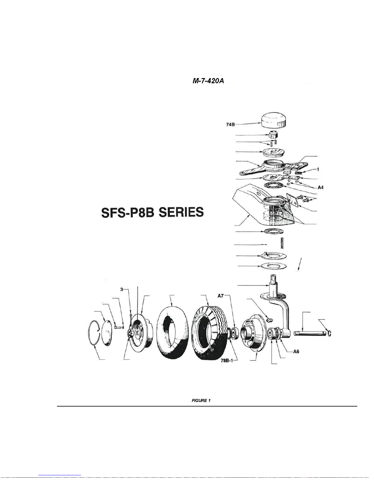
The tailwheel assembly consist of a Maule SFS-P8B Full Swivel Steerable Tailwheel
and a leaf type spring mounting. See Fig. 1 for detailed breakdown. If shimmy of the tailwheel becomes a problem, it should be lubricated and adjusted as follows:
A. DISASSEMBLY
1. Remove cap (74B) - may be pried off with flat side of a screwdriver.
2. Hold the fork (69B) and loosen the nut (A1).
3. With the nut removed, carefully remove the fork spindle from the rest of the assembly. Slowly rotate the fork back and forth while withdrawing it and collect the
loose parts.
4. Clean all of the metal parts in solvent. Inspect all parts and replace any parts that
exhibit excessive wear.
B. SHIM SELECTION
1. Position the bearings (A5) in bracket (71B) and slide the fork (69B) through the
bearings. Do not install any of the other parts at this time.
2. Slide lock ring (73B) over the threaded end of the fork spindle and run nut (A1)
down until it bottoms on the lock ring.
3. Tighten the nut moderately and note whether or not there is any end play in the
bearings. If there is no end play and no excessive rotational drag, shimming will
not be required. If there is any bearing end play, remove the nut and spindle and
install one (1) shim (83B) on the spindle and repeat the check. Normally only one
(1) or two (2) shims will be required to remove any bearing clearance. Too many
shims will cause the bearings to drag when the nut is tightened.
Rev. A
Page 31

MAULE AEROSPACE TECHNOLOGY, INC.
MAINTENANCE MANUAL
FOR
MX-7-420
28
C. ASSEMBLY
1. Grease pack roller bearings (A5) and lock pin (13AB) with wheel bearing grease.
Grease the parts adjacent to lock pin. Do Not grease friction washer (72B-4) or
the parts adjacent to it.
2. Place the roller bearings (A5) in their races, the felt seals (78B-2) on the bearings,
and the three (3) springs (76B) in the three deeper holes in bracket (71B). Place
friction ring assembly (72B-3) over the springs with the pin in the shallow hole in
bracket (71B). Grease may be used to hold the foregoing parts in place. Do not
allow any grease on the friction washer surface of the friction ring assembly (72B-
3).
3. Place shim(s) (83B) on lower shoulder of the spindle on fork (69B). Place the friction washer (72B-4) on the large diameter friction surface of the fork.
4. Carefully slide the fork spindle through the friction ring and bearings until the friction washer is bottomed against the springs. Make sure that all parts stay in
place.
Rev. A
Page 32
MAULE AEROSPACE TECHNOLOGY, INC.
MAINTENANCE MANUAL
FOR
MX-7-420
29
Rev. A
Page 33

MAULE AEROSPACE TECHNOLOGY, INC.
MAINTENANCE MANUAL
FOR
MX-7-420
30
5. Assemble lock ring (73B), arm (6) (with lock pin (13AB) and spring (14) installed),
shield (36), and pins (60AB) together as a unit. Make sure that the key end of
lock pin 13AB) is properly aligned with the slot in lock ring (73B).
6. Slide the lock pin subassembly over the threaded end of the fork spindle being
careful to keep the parts together. It will be necessary to retract lock pin (13AB)
slightly to clear wear plate (75B) as the assemblies are brought together.
7. Thread on nut (A1) and torque to 15-20 foot pounds. Fork should rotate by hand,
but with some drag, which is normal and caused by the friction washer.
8. Install cap (74B) with soft mallet. Check wheel rotation. There must be no play in
the bearings. Wheel should rotate with a slight drag.
D. TAILWHEEL INSTALLATION
1. Check all bolts and nuts holding the tail springs to the fuselage. They must be
tight so that there is no play or side movement in the springs or their attachment.
2. Tighten the bracket bolt and back off enough to install the cotter pin. There must
be no looseness or play between the bracket (71B) and the spring.
3. Install the connector springs, using the heavier spring on the right side. Install the
springs so that the light spring is compressed approximately 1/2 to 3/4 inch.
4. Inflate the tire to approximately 45 psi.
POWER PLANT SYSTEM
The power plant system consists of the turbine engine, engine mount, propeller, cowl,
engine controls, exhaust, air intake system and fuel system.
ENGINE:
Engine instructions covering the care and operation are covered in this manual and in
the Allison 250-B17 Engine Series Operation and Maintenance Manual.
ENGINE MOUNT:
The engine mount is a welded structure of chrome molybdenum steel (4130) tubing.
The engine is attached to the mount by means of three (3) point suspension to three (3)
mounting pads on the engine case. Each leg attachment incorporates a shock mount designed to absorb torsional fluctuation and vibrations of the engine. The engine mount assembly is bolted at the firewall to the fuselage structure by means of four (4) 3/8” attaching
bolts, (requiring a torque of 160-190 in lbs.) which should be checked for tightness periodically.
Rev. A
Page 34

MAULE AEROSPACE TECHNOLOGY, INC.
MAINTENANCE MANUAL
FOR
MX-7-420
31
An extremely close visual inspection of the engine mount should be made to periodically
check for cracks, dents, weld failures, etc., of the mount tubular members as well as the
general condition of the mount. At regular intervals, the attaching bolts at the engine should
be checked for tightness (required torque value of 37.5 - 41.5 ft. lb.) The rubber engine
mounts should be carefully inspected and replaced if necessary at each 100 hour inspection.
Excessive engine vibration at various RPM ranges should also prompt their inspection. Care
should be exercised to prevent the rubber mount’s contact with oil as this may result in their
premature deterioration. When torquing any engine or mount bolts, precaution should be
taken against any over-tightening, as this also may cause early failure.
PROPELLER:
The Hartzell propeller Installation, Operation and Service manual contains information
on the proper use and care of the propeller.
COWLING:
The cowling consists of an upper and lower section. Removal is accomplished by unlocking the dzus fasteners and removing the AN526 screws.
A periodic inspection of the cowling should be made checking for cracks, chafing, security of attachment, etc.
EXHAUST SYSTEM:
Check exhaust pipes for cracks. Check attachments for security.
Check the heater assembly for security and ensure that air hoses are clamped tightly
and are not worn or chafed.
FUEL SYSTEM
Two (2) 23.8 gallon main fuel tanks, mounted in the inboard end of the wings, have front
and rear outlets.
The fuel lines running from these tanks terminate at the fuel selector valve on the left
side kick panel. The fuel selector valve has two positions: BOTH and OFF. The fuel then
runs through the firewall to the main fuel pump, then to the fuel filter. From the fuel filter, the
fuel then passes through the emergency fuel pump to the engine driven pump on to the fuel
control.
Two (2) auxiliary wing tip fuel tanks, twenty-one (21) gallon capacity, are mounted in the
second from the outboard wing bay. They are fuel transfer tanks and simply supply fuel to
the main tank through a small vibrator pump.
Rev. A
Page 35

MAULE AEROSPACE TECHNOLOGY, INC.
MAINTENANCE MANUAL
FOR
MX-7-420
32
The fuel lines should be checked for cracks and chafing every 100 hours or annually
and the external fuel filter should be cleaned at the same time. The auxiliary tank transfer
pump strainers should be cleaned at the same interval. This is done by removing the pump
bottom with a 5/8” wrench. The pump is on the rear spar, inboard of the auxiliary tank, and
the bottom is exposed.
ELECTRICAL SYSTEM
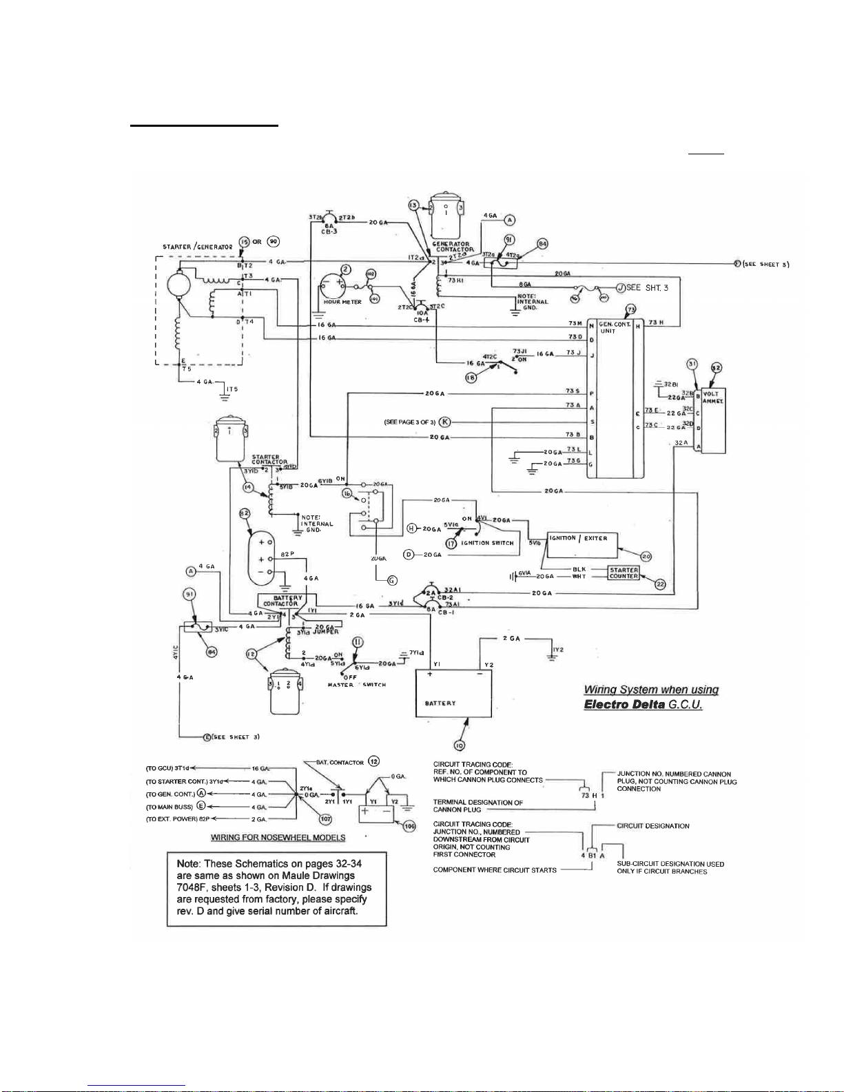
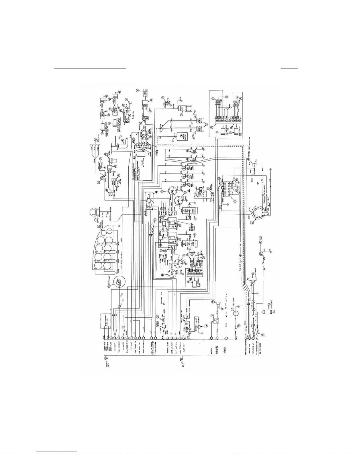
The electrical system is a 28 volt, 100 amp, direct current, single wire circuit using the airplane structure as a ground return to the battery. All wiring in the airplane is fabricated into
harnesses which are groups of related wires tied together. Most of the harnesses originate
at circuit breakers on the main bus (center of instrument panel) and terminate at the load
(light, pump motor, etc.) A wiring diagram is shown at the end of this manual.
CAUTION: Addition(s) of electrical equipment must not cause the total load to exceed
100 amperes.
BATTERY:
A lead plate type storage battery rated at 24 volts is installed in the battery box on right
side of firewall. The battery supplies current for the airplane electrical system when the master switch is in the “ON” position only.
The battery is the sealed type or the manifold vented type, with the base being integrally
vented. Tubes attached to the case vent the battery to the fuselage bottom. Battery caps
should be kept tight to prevent electrolyte spillage. If spillage does occur, the affected area
should be cleaned with a liberal application of an acid neutralizing solution such as baking
soda and water. The vent tube must be properly routed through the fuselage bottom as battery acid will destroy the fabric.
Some batteries are sealed recombinant design which do not require the external vent
tube.
This battery is considered fully charged at a hydrometer specific gravity reading of
1.265. A low charge would be 1.225 or lower. Operating with a low charge will shorten the
life of battery and can be prevented by recharging are operating with electrical equipment
turned off until the battery has been sufficiently recharged.
GENERATOR CONTROL SYSTEM:
Overvoltage protection is incorporated in the generator control unit which will latch off
regulator output after an overvoltage event. Reset of latch off caused by either overvoltage
or shorten output is accomplished by momentary turn off of supply voltage, i.e., to reset to
ON.
Rev. A
Page 36

MAULE AEROSPACE TECHNOLOGY, INC.
MAINTENANCE MANUAL
FOR
MX-7-420
33
The generator output is monitored by reference to the ammeter located in the left side of
the instrument panel. Should the generator of warning light illuminate, move generator
switch from off to reset to on. If system will not reset, investigate the electrical system malfunction.
The generator Control Unit in the electrical system contains the following functions:
a. Voltage regulator
b. Generator (line) contactor control
c. Overvoltage protection
d. Overload/Undervoltage protection
e. Reverse current protection
f. Reverse polarity protection
g. Anti-cycle protection
h. Latching field relay
i. Flash start relay
j. Overvoltage and Overload protection self test (using remote SW)
Rev. A
Page 37
MAULE AEROSPACE TECHNOLOGY, INC.
MAINTENANCE MANUAL
FOR
M-7-420
34
Electrical Schematic – Sheet 1 of 3
The wire numbering system has been designed to ease tracing a faulty wire. The code is as shown below the
schematic. Wires are plainly labeled near each end.
28 Volt
Rev. A
Page 38
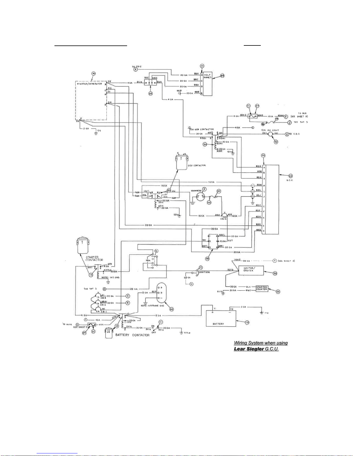
MAULE AEROSPACE TECHNOLOGY, INC.
MAINTENANCE MANUAL FOR M-7-420
Electrical Schematic – Sheet 2 of 3
28 Volt
35
Rev. A
Page 39
MAULE AEROSPACE TECHNOLOGY, INC.
MAINTENANCE MANUAL
FOR
MX-7-420
Electrical Schematic – Sheet 3 of 3
28 Volt
Rev. A
Page 40
MAULE AEROSPACE TECHNOLOGY, INC.
MAINTENANCE MANUAL
FOR
MX-7-420
Rev. A
 Loading...