

Mauell ME 3011b Instruction Manual

Manual ME3011b_E_v0707_Pre.doc 1/50
ME 3011b
Instruction Manual
Alarm Systems
SERIAL PRODUCTS
Digital Alarm Annunciator
Manual ME3011b_E_v0707_Pre.doc 2/50
1 – Information and Technical Data
Introduction
4
Warranty
4
Installation
5
Operation Principles
6
Technical Data 7
Modularity and arrangements 9
Dimensions
10
Panel Mounting 11
Product Identification 12
Product Code 13
Front display engraving/printing 14
Signaling sequences 15
Special Options 16
2 – Product Description
CM-0x – Master CPU’s Module 17
CM-03 – Master CPU 2v x 4h 17
CM-04 – Master CPU 4x x 2h 18
SM-02 – Slave CPU Module 20
EM-0x - Expansion Modules 21
EM-02 – Expansion Module 2v x 4h 21
EM-03 – Expansion Module 4v x 2h 22
EM-04 – Expansion Module 2v x 2h 23
Functions 24
3 - Installation
Power Supply 26
Inputs 27
Alarm Inputs 27
Remote push-button 27
GPS Synchronization (Option) 28
Power consumption 32
Outputs 29
24Vdc field output 29
External Buzzer output 29
Programmable relay outputs 29
Repeater relay outputs (RRO) (Option)l 29
Repeat relays for power fault detection (Option) 30
Flashing synchronization (Option) 31
Recommendations 32
Connection diagram examples 33
Standard connections – 24 Vdc – without RRO or Special
33
Connections with Vdc Fault at Point 2 and Vac Fault at Point 4 35
Terminal identification 37
New arrangements 41
SM-02 module positions 42
SM-02 position on 4h enclosure 42
SM-02 position on 8h enclosure 43
SM-02 position on 12h enclosure 44
Manual ME3011b_E_v0707_Pre.doc 3/50
SM-02 position on 16h enclosure 45
Configuration modes 46
4 - e.Tool ME3011 config - Configuration via serial interface
5 - Configuration via keyboard
6 – Communication Protocol - Serial Modbus RTU
7- e.Tool ME2011 view
This manual is subject to changes without previous advice
Revision Control
Author Version/Rev Date
mbe 0 16/07/2007

Manual ME3011b_E_v0707_Pre.doc 4/50
Dear Customer,
Mauell thanks you for trusting us on choosing our products. It is a pleasure to provide you all
necessary information on the newest member of its Mauell annunciator family.
This manual presents all information needed to connect and power up the annunciator, as well as
instructions for configuring it.
Mauell hopes that this manual helps you explore totally the potential of the new ME 3011
annunciator.
Please contact us, if any doubt persists about the equipment operation, after reading it. Our technical
team is always available to clear any doubt you may deem necessary.
Contact the nearest Mauell unit (please refer to the appendix) or send an email to
mauell@mauell.com.br; visit the website www.mauell.com.br; send a fax to +55 11 2117 5354 or
call +55 11 2117 5353.
In order to help us on our support service have the series number and the firmware version with
you, as these data are essential for clearing the doubts and for technical assistance.
The equipment manufactured and supplied by Mauell is guaranteed against any project and
manufacturing defect, when stored and used according to its technical characteristics, for a 12
(twelve)-month period from its installation or 18 (eighteen) month-period from the ex works delivery
date (which is the earliest).
During this period, Mauell will replace or correct, without any charges to the client, all out of
technical specification equipment parts. In other words, our warranty covers materials and labor in
the correction of eventual defects eligible for being covered by our warranty.
These operations will be carried out in our nearest unit (as previously agreed upon) or at Helmut
Mauell do Brasil to where the equipment may be sent.
In case of doubt about the use of the equipment, due to the warranty and its effects, please contact
our commercial and technical departments.
INTRODUCTION
WARRANTY

Manual ME3011b_E_v0707_Pre.doc 5/50
All annunciators have an appropriate package for air or road transportation. When receiving the
equipment, the visual inspection may be carried out to check if there were damages during
transportation. If so, it is necessary to contact immediately the receiving sector of your company,
which may notify your insurance company and Mauell so the involved parts may adopt the necessary
measures to repair the damages and to initiate the reimbursement of eventual expenses.
The incorrect use and wrong handling of the equipment are not covered by Mauell general
guarantee. Therefore, it is essential that the installer takes some measures, before executing the
installation and powering of the equipment, as mentioned below:
Avoid mechanical impacts to the equipment or falls, which cause frame arching or back
terminal breaking.
Avoid that water or other liquid gets into the annunciator, as the liquid may cause short-
circuit to the internal circuits and, consequently, bad contacts in the future.
Avoid that exte rnal objects get into the annunciator through the vents, thus, whenever it is
necessary to carry out any work involving drilling or panel plate thinning, where the
annunciator is installed, the equipment may be protected with paper, plastic and other
material so the debris do not get into the annunciator, causing poor operation.
Check the voltage levels and the correct identification of the cables before executing the
equipment connection. A wrong connection can cause short-circuit and damage to the
equipment in an irreparable way.
The frontal modules may be removed with the aid of a blade, which may be inserted
between two modules, carefully, forcing the removal of the desired module. This operation
may be carried out carefully and patiently in order to prevent damages to the front part of
the modules or to the grid brackets of the module.
The access to the electronic circuits of the equipment is carried out from the front part,
removing the front modules, as described above, disconnecting the back pluggable
terminals, without disconnecting the wires, from which the electronic part of the equipment
may be removed. After the repair, the electronic part may be replaced and the terminals
plugged again. When reconnecting, note with the maximum care, the proper position of
each terminal.
The cleaning of the front part of the annunciator may be carried out with a soft cloth,
slightly wet, with neutral detergent. The equipment may not be submitted to the direct
spray of liquids and care must be taken so the liquids do not get into it.
INSTALLATION

Manual ME3011b_E_v0707_Pre.doc 6/50
Alarm annunciators have the main function of safely signaling critical statuses of installations, aiming
at their integrity.
They signal acoustically and optically equipment alarms in a standardized way, within the highest
ergonomic and cognitive possible standard.
It is recommended, in general, to carry out the direct connection of electric field alarm signals to the
annunciator, preventing loops through digital automation and control systems. Thus, the necessary
operating safety level is achieved.
The maximum alarm signal cable length is 600 m (unshielded) or 1000 m (shielded). These
maximum values may be strongly reduced in areas with very high electromagnetic fields, for example
in the case of open air cable trays within substations. It is, also, of paramount importance to place
the signal cables in trays carrying cables with homogeneous voltages. Placing high and low voltage
cables in conjunction within the same cable tray may cause serious annunciator malfunctions or even
hardware damages.
The ME 3011 annunciator, the new member of Mauell annunciator family, keeps one of the most
important characteristics of ME 3010 series, which is the modularity of the alarm windows. The
processing fundament of the alarm signs is now carried out through latest generation micro
controllers, with high performance RISC architecture.
So, ME 3011 annunciator incorporates all the advantages of a micro processed system, such as
configuration of the annunciators main functions through the front keyboard, or also via
configuration software, available at
www.mauell.com.br for download.
This way, the ME 3011 annunciator provides all conventional functions of alarm announcing together
with new and advanced communication function in local network and event recording, among
others.
These functions will be described in details throughout this manual.
OPERATION PRINCIPLES

Manual ME3011b_E_v0707_Pre.doc 7/50
1 - Supply Voltage
1.1 PS-05 Power Supply
24 Vdc ± 20%
Input: 19 to 264 Vdc and / or 90 to 264 Vac
1.2 PS-06 Power Supply (Option)
Auxiliary field output: 24Vdc / 0,75A
1.3 Special Option PSFD Power Supply Fault Detector (PSFD) for Vdc and/or Vac
1.4 Note: All power supplies are integrated into the annunciator
2 - Inputs
Alarm Inputs 4 up to 252
Isolation Opto couplers
Input Voltages
24, 48 , 60, 110 / 125 Vdc ± 20%; 110 / 127, 220 Vac ± 20%
Input Current 3 mA (typical)
2.1
Input Filter lower value = 5 ms, programmable in steps of 2.5 ms
External Push-Button Station 24Vdc
Isolation Opto couplers
2.2
Functions
Sound Acknowledge (HA), Light Acknowledge (LA), Reset (RE),
Light Test / Function Test , Sleep Mode (SLM), Keyboard OFF
(K
BOFF
)
Synchronism with GPS and/or
Flashing
24Vdc
2.3
Isolation Opto couplers
3 - Outputs
3.1 Relays
3 contact free freely programmable relays for various functions,
e.g., external buzzer, voltage fault, alarm group, etc
3.2 Sound Indication 90 db / 10 cm, 4 kHz
3.3 Repeat relays (Option)
1 contact for each alarm point, as option
Note: Field Voltages over 125 Vdc or Vac do not support repeater
relays.
3.4
Repeat relays for Power Supply
Fault Detector (PSFD) (Option)
1 contact for each Power Supply Fault detector (PSFD)
Note:
Contact capacity for all relays is 5A / 24Vdc for resistive load.
Maximal switching voltage: 125Vdc/250 Vac
4 - Interfaces
RS232C bi-directional
Baud rate: 9600,n,8,1
4.2
Communication RS232C
(Option)
Protocol: Modbus RTU (Slave) or Modbus RTU (Slave)+TS
RS 485 Bi-directional serial communication (configurable)
Baud rate: 100 a 19200
Parity: even, odd or none
Stop bits: 1 or 2
4.3 Communication (Option)
Protocol: Modbus RTU (Slave)
TECHNICAL DATA

Manual ME3011b_E_v0707_Pre.doc 8/50
5 - Event Register (Option)
5.1 Events 1000, with Time Stamp
5.2 Resolution 1 ms, samples 2,5 ms
5.3 Interfaces RS232C or RS485
5.4 Protocols Modbus RTU (Slave)
6 - Visualization
Light Indication
Back light Available in red, yellow, green, white and blue colors
Ultra Bright Back light Available in red, yellow, green, white and blue colors
Back Light Socket (Option)
Available in red, yellow, green, white and blue colors, on sockets
to allow color change at the field.
Led 5 mm visible red, yellow, and green color leds
6.1
Special Option More than 1 color per annunciator
Fast: approx. 1.2 Hz
6.2 Flashing frequency
Slow: approx. 0.4 Hz
Windows
Dimension 24 x 48 mm
Back light White translucent modules
6.3
Led Gray RAL 7032 polycarbonate modules
7 – General
7.1 Alarm sequence ISA 1, 1A, 1B, 2A, 2C, 4A, 4AR; others on request
Operation temperature: 0 to 55°C
Storage temperature: -20 to 80°C
7.2 Environment
Relative Humidity: 0 to 95 %, without condensation
Front: IP41
7.3 Protection class
Enclosure: IP30
7.4 Isolation 3000 V
eff
: IEC 60950-1 FAZER com Lote Piloto !!!
Immunity: DIN EN 61000-6-2
7.5 EMC Compliance
Emission: DIN EN 61000-6-4
7.6
ESD DIN EN 61000-4-2
7.7 Electromagnetic Field Immunity DIN EN 61000-4-3
7.8 RF Frequency Immunity DIN EN 61000-4-6
7.9 Burst DIN EN 61000-4-4
7.10 Surge DIN EN 61000-4-5
7.11 Voltage Dips DIN EN 61000-4-11
7.12 Terminals Terminal connectors (removable) for cables up to 2.5 mm²
7.13 Tropicalization Special Option
TECHNICAL DATA
Manual ME3011b_E_v0707_Pre.doc 9/50
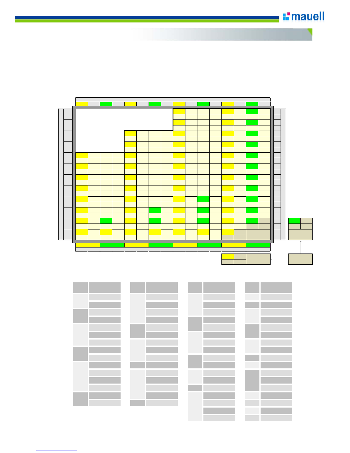
The minimum configuration possible for the annunciator is a central module with 4 alarm points, and dimension of 2V x
4H or 4V x 2H. (see shaded portion on lower right corner of diagram below)
Expansion modules can be added to this central unit, with 4 or 8 alarm points each, always in 2V x 2H or 2V x 4H
modularity basis. So the subsequent configurations are: 8, 12, 16, 20, 24, 28 points and so on, up to a maximum of
252 alarm points.
The module arrangement follows the diagram below.
Enclosure arrangement:
MODULARITY AND ARRANGEMENTS
16 15 14 13 12 11 10 9 8 7 6 5 4 3 2 1
24vx8h=
188P
24vx4h=
92P
24vx2h=
44
P
24
23
22vx8h=
172P
22vx4h=
84P
22vx2h=
40
P
22
21
20vx12h=
236P
20vx8h=
156P
20vx4h=
76P
20vx2h=
36
P
20
19
18vx12h=
212P
18vx8h=
140P
18vx4h=
68P
18vx2h=
32
P
18
17
16vx16h=
252P
16vx12h=
188P
16vx8h=
124P
16vx4h=
60P
16vx2h=
28
P
16
15
14vx16h=
220P
14vx12h=
164P
14vx8h=
108P
14vx4h=
52P
14vx2h=
24
P
14
13
12vx16h=
188P
12vx12h=
140P
12vx8h=
92P
12vx4h=
44P
12vx2h=
20
P
12
11
10vx16h=
156P
10vx12h=
116P
10vx8h=
76P
10vx4h=
36P
10vx2h=
16
P
10
9
8vx16h=
124P
8vx12h=
92P
8vx8h=
60P
8vx6h=
44
P
8vx4h=
28P
8vx2h=
12
P
8
7
6vx16h=
92P
6vx12h=
68P
6vx10h=
56
P
6vx8h=
44P
6vx6h=
32
P
6vx4h=
20P
6vx2h=
8
P
6
5
4vx16h=
60P
4vx14h=
52
P
4vx12h=
44P
4vx10h=
36
P
4vx8h=
28P
4vx6h=
20
P
4vx4h=
12P
4vx2h
=4
P
4
4vx2h
=4
P
4
3
2vx16h=
28P
2vx14h=
24P
2vx12h=
20P
2vx10h=
16P
2vx8h=
12P
2vx6h=
8P
2vx4h
=4P
2
1
4
3,5
3
2,5
2
1,5
1
0,5
2vx4h
=4P
43
CM-0x
Número de Módulos na Vertical
y = 12
y = 11
y = 10
y = 9
Number of horizontal points (h)
y = 8
y = 7
CM-03
CM-04
Min.
arrangements
Number of vertical poinsl (v)
Number of horizontal modules
y = 2
y = 1
y = 6
y = 5
y = 4
y = 3
Nr. of
Points
Nr. of
Points
Nr. of
Points
Nr. of
Points
4v x 2h 16v x 2h 28v x 2h
108
14 v x 8 h
2v x 4h 8v x 4h 14v x 4h
116
10 v x 12 h
2v x 6h 4v x 8h 4v x 14h 16v x 8h
6v x 2h 2v x 16h 10v x 6h 8v x 16h
8v x 2h 18v x 2h 6v x 10h 18v x 8h
4v x 4h 6v x 6h 16v x 4h 12v x 12h
2v x 8h 20v x 2h 8v x 8h 20v x 8h
10 v x 2 h 10 v x 4 h 4 v x 16 h 10 v x 16 h
2v x 10h 4v x 10h 18v x 4h
164
14 v x 12 h
12 v x 2 h
40
22v x 2h 6v x 12h
172
22 v x 8 h
6v x 4h 12v x 4h 20v x 4h 24v x 8h
4v x 6h 8v x 6h 10v x 8h 16v x 12h
2v x 12h 6v x 8h
84
22 v x 4 h 12 v x 16 h
14v x 2h 4v x 12h 24v x 4h
212
18 v x 12 h
2v x 14h
48
26 v x 2 h 12 v x 8 h
220
14 v x 16 h
8v x 12h
236
20 v x 12 h
6v x 16h
252
16 v x 16 h
188
24
92
16
68
20
44
76
140
60
36
156
Arrangement Arrangement
4
28
52
8 124
56
12
32
Arrangement Arrangement
Manual ME3011b_E_v0707_Pre.doc 10/50
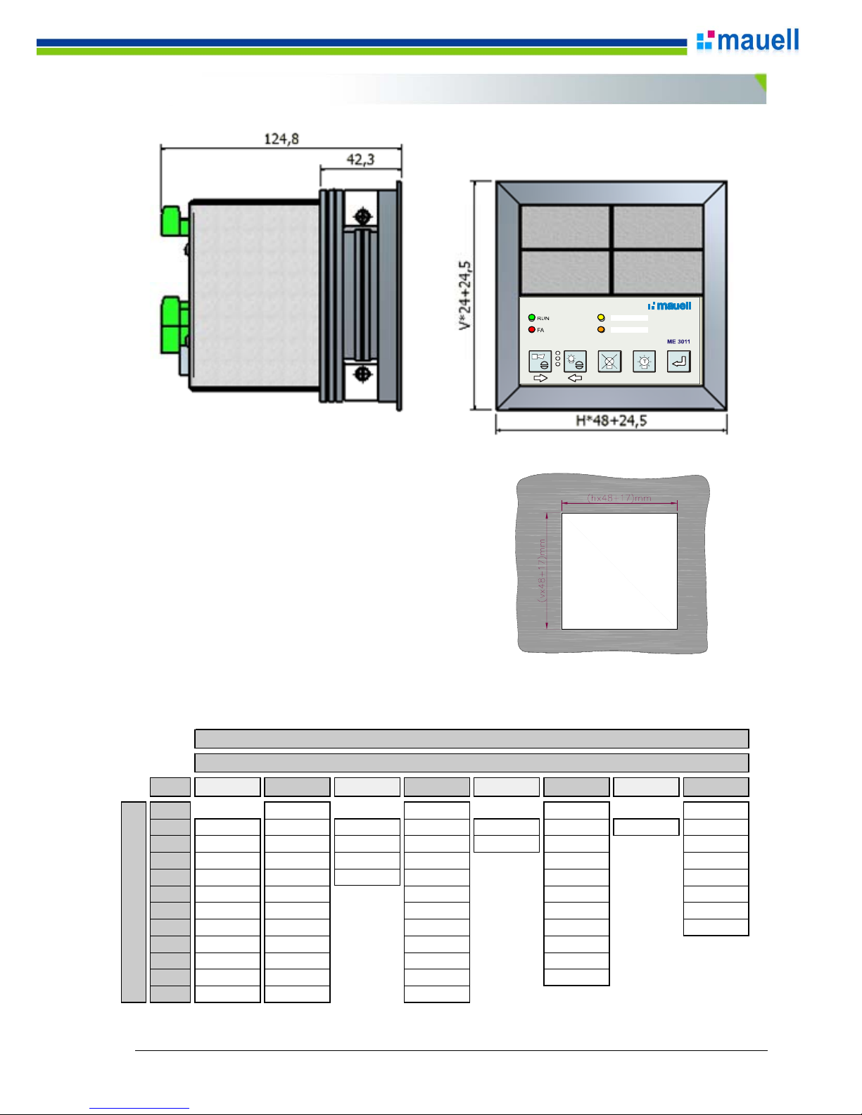
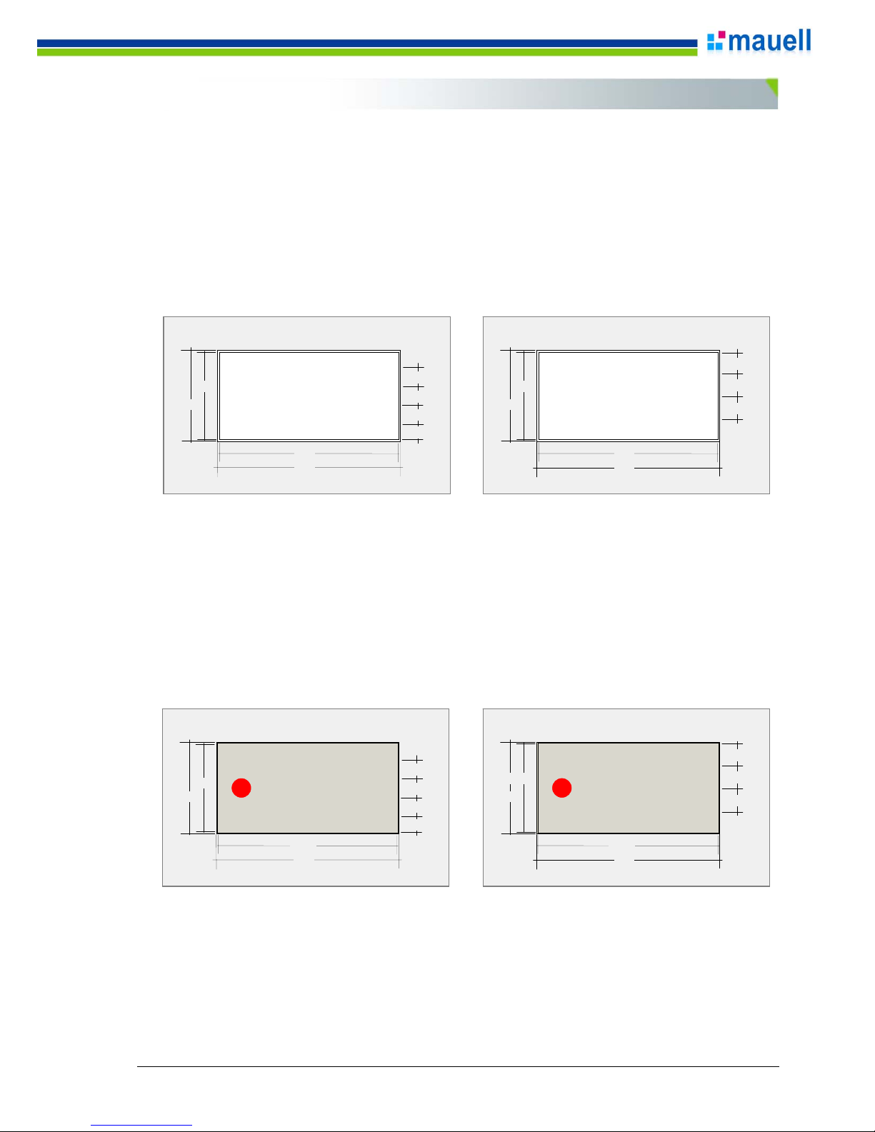
DIMENSIONS
Points
2
65 x 209 65 x 401 65 x 593 65 x 785
4
113 x 113 113 x 209 113 x 305 113 x 401 113 x 497 113 x 593 113 x 689 113 x 785
6
161 x 113 161 x 209 161 x 305 161 x 401 161 x 497 161 x 593 161 x 785
8
209 x 113 209 x 209 209 x 305 209 x 401 209 x 593 209 x 785
10
257 x 113 257 x 209 257 x 305 257 x 401 257 x 593 257 x 785
12
305 x 113 305 x 209 305 x 401 305 x 593 305 x 785
14
353 x 113 353 x 209 353 x 401 353 x 593 353 x 785
16
401 x 113 401 x 209 401 x 401 401 x 593 401 x 785
18
449 x 113 449 x 209 449 x 401 449 x 593
20
497 x 113 497 x 209 497 x 401 497 x 593
22
545 x 113 545 x 209 545 x 401 545 x 593
24
593 x 113 593 x 209 593 x 401
16
v
(y)
Cutout table [height (h) x widt h (v)] mm
h (x)
2468101214
Manual ME3011b_E_v0707_Pre.doc 11/50
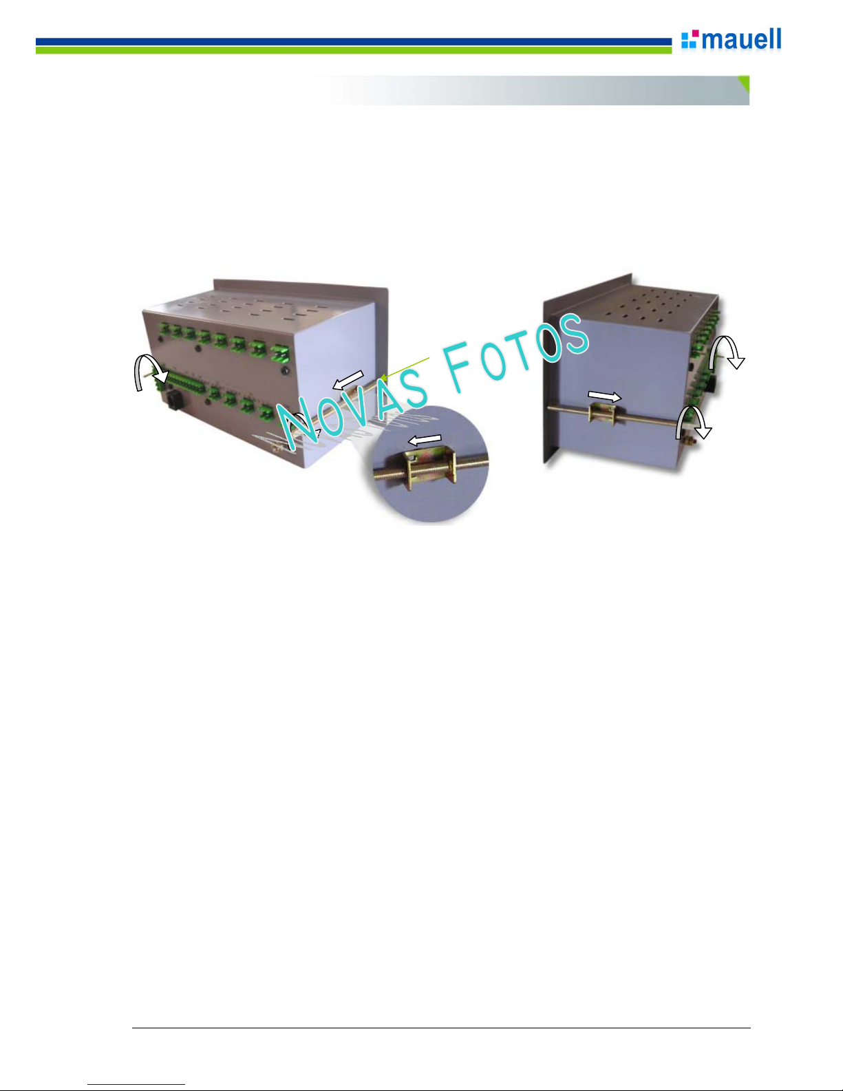
Each ME 3011 is shipped with a certain amount of panel clamps according the annunciator’s size.
1 – Locate the panel clamps inside the packing box and prepare the mounting
2 – Insert the annunciator into the cutout
3 – Insert the panel clamps into the lateral orifice, selecting the sides that provides the best mounting
4 - Srew, pressing lightly onto panel front plate
PANEL MOUNTING
Panel clamp

Manual ME3011b_E_v0707_Pre.doc 12/50
1 – Identification Label
1.1 Code
Product code with 15 digits
1.2 Serial#
Product serial number YY/9999, where YY is the year and 9999 is a sequential number
1.3 FW:
Identifies the firmware version from the annunciator
YYMMDD999 = year, month, day and firmware version
1.4 Power Supply:
Power supply voltages
Standard:
19-264Vdc/90-264Vac
With Power Supply Fault Detector (PSFD) are specified the requested voltages.
Example: Digit 7 = E, indicates this option and the voltages specified by the customer was 125Vdc and 220Vac:
125Vdc/220Vac
1.5 Field:
Indicates the field voltage of the annunciator
PRODUCT IDENTIFICATION
Indústria Brasileira / M ade in Brazil / Fabriqué au Brési l
www.mauell.com.br
Power Supply:
19-264 Vdc / 90-264 Vac
Helmut Mauell do Brasil
ME3011b
Alarm Annunciator
Field:
Serial #:
07/b1001
FW:
Code:
004424D11612000
70515300 24 Vdc

Manual ME3011b_E_v0707_Pre.doc 13/5
0
Go to the ME3011b Codification:
PRODUCT CODE
ME3011b - Code
012 28 FE 44 512 00 1
Code:
012 28 FE 44 51 2 00 1
Dígito >1234567891011121314
15
Enclosure
12
0
Power Supply
PSFD Vdc Vac
Light Indication
7
Y
2
G
1
B
1
W
1 TOT= 12
RS485 Protocol Engraving
Lines
Cable
PÇ P
Ç
Return to Manual
Set Quantity for each color!
11
Tropicalization
PC
R
B and W only for Back Light
Complementar Informations
ISA Sequence
2
ME3011b BL Alarm Annunciator - 12 Alarm Points - 2V x 8H:
Special Options
Only for more that one color
Interface
Set the PSFDs Voltages !!
ME3011b QTY =
Nr. of Points
1
Power Supply Fail Detector
SoftwaresQTY QTY
Power Supply 19-264 Vdc / 90-264 Vac - PSFD at Keyboard, BL 5 Colors, 110/125 Vdc Field Voltage with RRO,
RS232C (R) + RS485 + ER + GPS Sync, Modbus RTU (Slave) + ER, with Engraving and Special Options.
RRO (Repeater Relays)Field Voltage
w/ SO
= Nr. of Points
012
BL 5 Colors
19-264 Vdc / 90-264 Vac - PSFD at Keyb o ard
110/125 Vdc
110/125 Vdc
RS232C (R) + RS485 + ER + GPS Sync
Low reliefModbus RTU (Slave) + ER
w/ SO
no (Standard)
ISA 2C / (M) - Standard
012P - 2V x 8H
Cable CS-02 - RS232C - 5 m
e.Tool ME3011b -view
110 Vdc
220 Vac
Manual ME3011b_E_v0707_Pre.doc 14/50
1 – Low Relief Engraving
1.1 – Back Light Display
LB 24 x 48 – White Translucent - Code: 83.53.002
Character height = 3 mm Maximum number of characters per line = 19 Maximum number of lines = 4
1.2 – LED Display
MK 24 x 48 - RAL 7032 color - Code: 83.52.003
Character height = 3 mm Maximum number of characters per line = 15 Maximum number of lines = 4
ABCDEFGHJKLMNOPRSTU
ABCDEFGHJKLM
ABCDEFGH
47
48
24
23
5,5
6
6
ABCDEFGHJKLMNOPRSTU
ABCDEFGHJKLM
ABCDEFGH
47
48
24
23
5
5
4
5
ABCDEFGHJKLMNOP
ABCDEFGH
ABCDEFGHJKLMNOP
47,5
48
24
23,5
6
6
6
ABCDEFGHJKLMNOP
ABCDEFGH
ABCDEFGHJKLMNOP
ABCDEFGH
47,5
48
24
5
5
4
5
23,5
FRONT DISPLAY INSCRIPTIONS
Manual ME3011b_E_v0707_Pre.doc 15/50
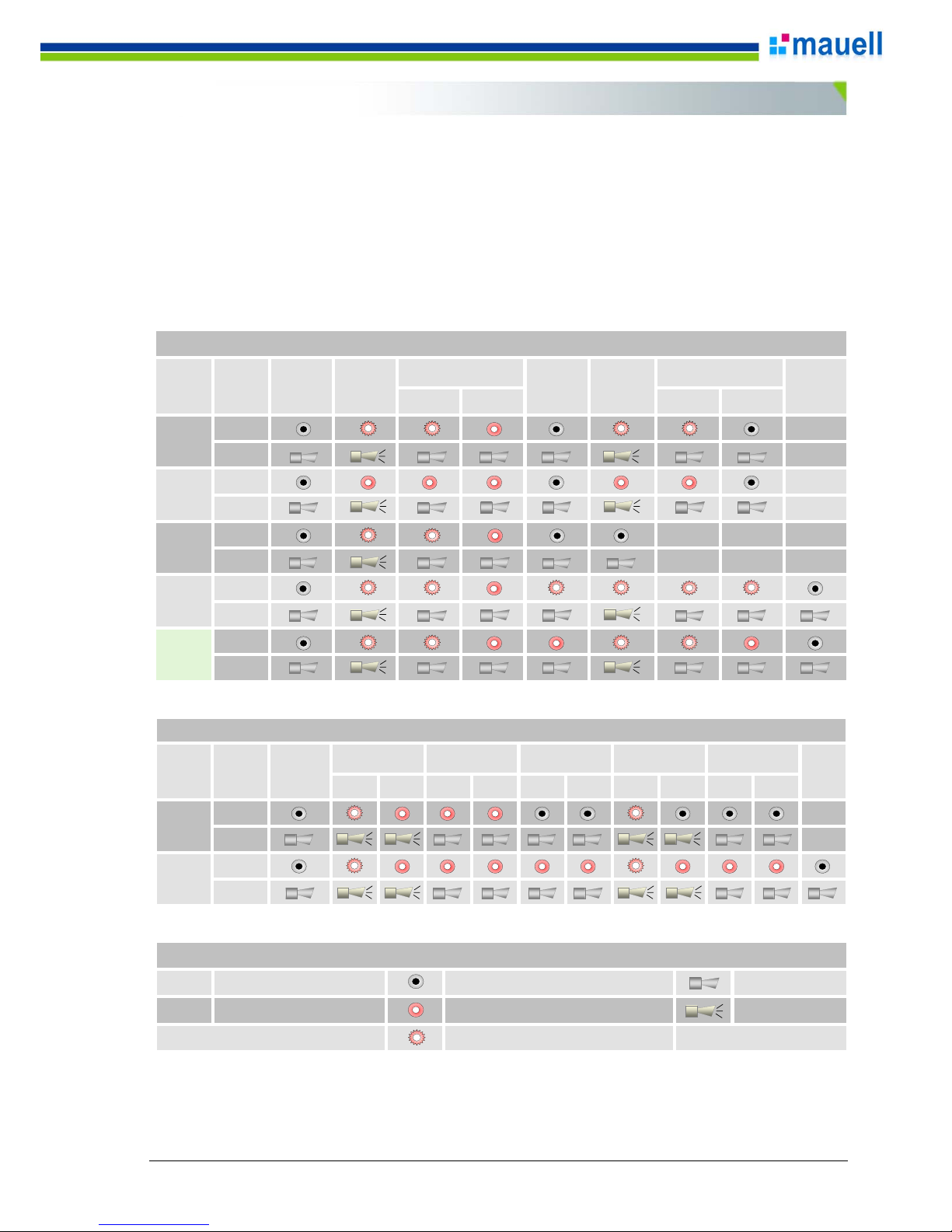
The ME 3011 can be configured in order to comply with 16 signaling sequence. Among them the most important are
the following:
ISA-RP 18.1/
(ISA-S18.1)
:
ISA1/
(A)
, ISA-1A/
(A-5)
, ISA-1B/
(A-4)
, ISA-2A/
(R-8)
, ISA-2C/
(M)
, ISA-4A/
(F1A)
, ISA-4AR/
(F1M)
etc.
Other sequences can be implemented on request.
SIGNALING SEQUENCES
F
S
Fast
Slow
Led off
Led on
Led intermittent
Buzzer off
Buzzer on
LEGEND
SOUND LIGHT SOUND LIGHT
Light
Sound
Light
Sound
Light
Sound
Light
F F S F F S
Sound
Light
Sound
ISA 2C
(M)
(default)
ALARM NORMAL
ISA 1
(A)
ISA 1A
(A-5)
ISA 1B
(A-4)
ISA 2A
(R-8)
REF ISA
ALARM SEQUENCE
ACKNOWLEDGE
RESETABNORMAL
ACKNOWLEDGE
BACK TO
NORMAL
BACK TO
NORMAL
BEFORE
ACKNOWL.
INITIAL SUBSEQ. INITIAL SUBSEQ. INITIAL SUBSEQ. INITIAL SUBSEQ. INITIAL SUBSEQ.
Light
Sound
Light
Sound
ISA 4R
(F1M)
REF ISA
ALARM NORMAL
ACKNOWLEDGE
RESET
PRIMARY ALARM SEQUENCE (1st. EVENT)
ISA 4A
(F1A)
ABNORMAL ACKNOWLEDGE BACK TO NORMAL
BACK TO NORMAL
BEFORE ACKNOWL.
 Loading...