

Mattson SQ816, Division 6 User Manual
1

Table o’ Contents
Welcome ......................................................................................................................... 3
Unpacking, Power Requirements, and Power Up Procedure ......................................... 4
SQ816 Panel Layout ....................................................................................................... 5
Definitions ....................................................................................................................... 6
Timing Section ................................................................................................................. 8
Stage Control Section ................................................................................................... 10
Stage Matrix ................................................................................................................. 11
Response Control Section ............................................................................................ 13
Output Section ............................................................................................................... 14
Interface Section ........................................................................................................... 16
User-Programmable Functions ..................................................................................... 17
Adjustments and Trim Procedures ............................................................................... 22
Ver 1.27 2013-02-01
2

Welcome
Thank you for becoming the proud owner of one of the most exciting new products to come from the
combined laboratories of Mattson Mini Modular and Division 6: The SQ816 Analog Step Sequencer.
The SQ816 sequencer is a joint project between Mattson Mini Modular and Division 6 that has been in
development for more than a year. And what a sequencer it has become!
There are two formats - each is available from either the Division 6 or the Mattson Mini Modular web sites,
or from select dealers.
Division 6: http://division-6.com/shop/Synthesizers/
MMM: http://www.mattsonminimodular.com/shop/index.php?main_page=index&cPath=5_10
The Mattson Mini Modular format is comprised of two separate modules. The main SQ816 sequencer
module is a 3-wide Mattson format module and the Expansion module is a 2-wide Mattson format module.
The Division 6 SQ816 sequencer module combines both the Main SQ816 sequencer and Expansion
modules into one 52HP (10-3/8” W) Eurorack format module.
I have over 30 years of synthesizer history starting with the invention and production of the first actively
portable self-contained synthesizer, which I named the Syntar in 1978. It was innovative for its time and
was the first “keytar” produced. I use the term “Keytar” in its commonly utilized generic term.
I’ve been playing with analog step sequencers for 30 plus years, and decided to produce a system that had
all of the features I enjoyed, the features I always wished they had, and designed out the stuff I didn’t like. I
also added a few extra things just because I could, and because I thought they were awesome features to
try! The SQ816 is the result of that determination.
I designed the hardware and incorporated the help of Division 6 to write and implement the software to
create a truly amazing step sequencer.
The SQ816 is designed to be primarily utilized as a CV/Gate controller. There are numerous inputs and
outputs to help facilitate stand-alone operation with virtually any analog CV/Gate synthesizer system and
expansion interfaces to allow the operation of multiple SQ816 sequencers in series or parallel.
This manual has several parts. There is a Definitions section to help you understand the terminology utilized
within the text of this manual, a Panel Layout section which explains the primary panel control and I/O
functions, dedicated sections for each of the major function blocks on the SQ816, and a programming
section which explains the multitude of user-programmable features.
A Calibration section is also provided to allow you to tweak some of the functions to suit your preference or
“dial in” some parameters to match outboard system responses. The calibrations detailed allow the user to
change LED brightness, adjust the upper and lower ranges of the internal VC clock, and tweak in all of the
1Volt / Octave input and output functions.
We will be developing short videos that highlight specific functions and show a few hints and tips. This will
be an ongoing project and will be available for viewing on my YouTube channel. My user name on YouTube
is MMModsynth, so check it often for new videos.
Software updates via USB will be available on the SQ816 page on the Mattson Mini Modular WIKI site and
on the Division 6 web site when they are available.
Thank you again. We’ve had a lot of fun developing this product, and we’re looking forward to seeing the
creativity from our customers utilizing this module.
George Mattson
3

Unpacking, Power Requirements, and Power Up Sequence
What’s in the box? When you open the packaging for your SQ816 sequencer, you’ll find:
The SQ816 sequencer
Programming Quick Reference card
Jacklight
Power cable
USB cable
Mounting screws (4)
Power requirements: The Mattson/ Division 6 sequencer was designed to operate from either the standard
Eurorack power standard of +/- 12VDC or the +/- 15VDC power found on many other synthesizer systems.
The +V line draws 86mA, while the –V line draws 32mA.
The SQ816 has a 10 pin dual row keyed power header and a 6 pin MTA header on the main board. Either
connector can be used to power the system.
The supplied power cable has a 10 pin keyed socket on one end of the ribbon cable and a 16 pin keyed
socket on the other end. The 10 pin socket connects to the 10 pin keyed header on the lower-right of the
SQ816 sequencer main board (when viewed from the rear). The “stripe” on the ribbon cable is oriented to
be located toward the bottom of the circuit board. Since the supplied power cable is keyed, you can’t plug it
in backward. If you use a different power cable that isn’t keyed and connect it backward, no problem - the
SQ816 automatically orients the power to the proper polarity. Connect the keyed 16 pin socket on the other
end of the ribbon cable to your system power bus. If your power distribution headers aren’t keyed, verify the
stripe location prior to connecting. The stripe indicates the negative voltage (V-).
The SQ816 sequencer clock is calibrated for the power scheme utilized based on the format provided. The
only effect of using a higher or lower voltage power supply is that; the lower the power supply voltage, the
faster the VC clock will cycle and it will need to have the range adjusted. Refer to the Adjustments and Trim
Procedures section at the end of this manual for further information.
Power up sequence: On initial power up, the SQ816 will initially perform an LED check by producing three
scans across the Stage Status LEDs. On the first scan, the LEDs will light red. On the second scan, the
LEDs will light yellow, and on the third scan the LEDs will light green. On each scan, the clock LED will be lit
continuously at the current scan color.
After the LED check, The LEDs will go dark and then display the software version number. The stage
number of the LED will indicate the numeric value (1-8), and the clock LED is utilized to indicate the
numeral 0 (zero). The first LED indicates the integer portion of the version number. The second LED
indicates the first decimal number. The third LED indicates the second decimal number.
The SQ816 sequencer will enter ready mode (no stages lit, clock LED flashing) after the Version Number
display
We’ve also created a short video to illustrate the power up routine:
www.youtube.com/watch?v=jns2ajQR1JE
4

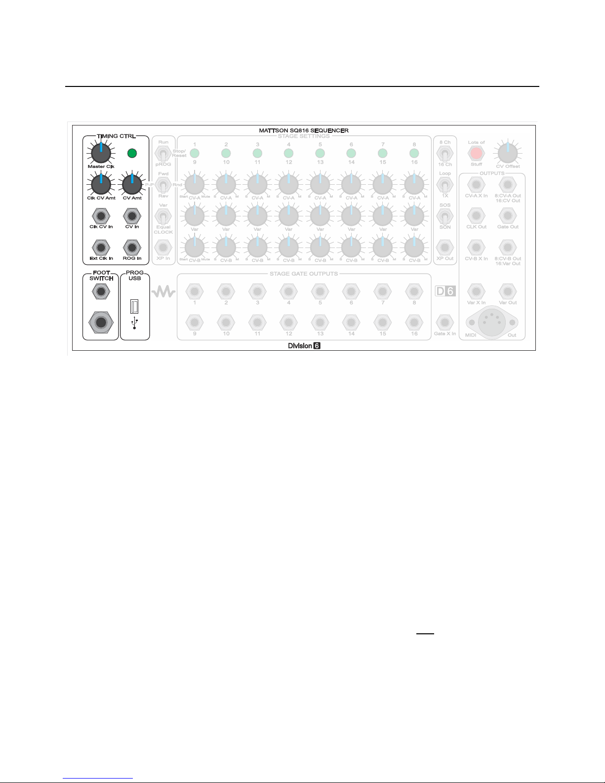
SQ816 Panel Layout
5

Definitions
Ready or “Stand by”: Clock running, no stages active. Clock Indicator LED flashing red at clock rate
(indicating Gate Mute)
CV: Control Voltage. A voltage used to change an operational parameter. Usually between +/- 15VDC.
VC: Voltage Controlled. A functional parameter that can be altered by applying a Control Voltage.
1V/Oct: One Volt per Octave. A “standard” where each volt applied will cause an operational change of one
octave on pitch related devices.
Gate: A voltage change used for initiating a specific event. Usually going from 0V to either +5V or +15V
Stage Gate: A gate generated from the activation of a specific stage event. The SQ816 stage gates
produce a +5V gate pulse.
“Start” or “Beginning”: The beginning of a sequence. Stage 1 in Forward mode. Stage 8 in Reverse / 8
channel mode. Stage 16 in Reverse / 16 channel mode.
Start Zone: A region in the lowest CCW position of the CV-A and/or CV-B controls.
In pROGram mode, the active stage LED will flash when the region is active
In Run mode, the sequence will progress to the stage prior to the stage set as “Start”, and
then return to the beginning when the sequence is started.
In Loop mode, the beginning is the first stage of a local sequence.
In 1X mode, the beginning is assumed to be off system. The sequence will truncate,
generate an XP out pulse and enter Ready Mode.
Last stage: The last stage of a programmed sequence before repeating, changing direction, or going into
Ready Mode.
ROG: Run-On-Gate. A sub function of pROG mode where stage advances occur only when a gate is
applied to the ROG input.
PIG: Pause-Including-Gate. A Run mode operation where a gate applied to the ROG input will stop stage
advances until the Gate is released. The main gate continues to be generated at the clock rate.
SOS: Start-On-Stage. A start operation where starting the stage advancement will play the current stage
first before advancing.
SON: Start-On-Next. A start operation where starting the stage advancement will play the next stage first
before advancing.
Loop/1X: Control for determining if a sequence repeats, or makes one pass and enters Ready mode.
Var: Variable. A control voltage generated by the Var settings. Primarily utilized to vary the clock rate on a
per stage basis.
XP: eXPansion. Used for off-module interfacing and timing.
6

Definitions (continued)
Zoned Mute: Two regions in the upper CW position of the CV-A and CV-B controls for determining if the
Main Gate or Main Gate and Stage Gate are suppressed for a specific stage. During a stage specific mute,
the previous valid generated CV if held during the muted stage.
X in: eXternal Input. Used for interfacing and summing external CVs to the function specific output.
Local: Refers to on-system operations.
Global: Pertaining to all stages, or a bank of stages during an operation. Usually selected by programming
in Ready mode.
Clock: Timing device for determining the stage advance rate. An external clock applied to the Ext Clk input
interrupts and replaces the internal VC clock. The Tap Tempo feature interrupts and replaces the internal
VC clock or the external clock.
Quantize / Linear: Linear mode allows for a continuous sweep from 0-3 Volts using the control knob for a
stage. No MIDI data is output for a bank in Linear mode. In Quantize mode, the full CV range is stepped in
semitone values in the 12 semitone/octave western scale. MIDI note data output is enabled for a bank set
to Quantize mode.
Bus: Also called a bank. The output signal from a specific row of stage settings.
7
Timing Section
The Timing Section sets stage advance timing and contains the LED Clock Indicator
Master Clk: Rate control for internal clock. Using the Master Clock panel control, the minimum rate is about
10 seconds per stage and the maximum rate is about 100 Hz. Both limits can be affected by a control
voltage applied to the Clk CV In jack and adjusted with the Clk CV Amt control. With a negative CV
applied, the minimum rate is about 1.5 hours per stage. With a positive CV, the maximum rate tops out at
about 133 Hz before the LEDs and gate start cutting out, but that can be fun too.
LED Clock Indicator: The Clock Indicator LED flashes to indicate the frequency of the internal clock
oscillator. The clock LED is also used to confirm that a user function has been programmed, and the LED
color will indicate one of the following
Green: Internal VC Clock or external clock at the Ext Clk In jack is in control of the stage advance
timing. The LED flashes at stage advance clock rate.
Yellow: Indicates user programmed Tap-Tempo control of the stage advance. VC internal and
external clocks are disabled.
Red: Indicates that the main gate output is disabled (muted) either from a stage setting or manually
invoked.
Clk CV Amt: Clock Control Voltage Amount. Adjusts the amount of modulation from the Clk CV In jack.
Clk CV In: Control Voltage input for modulating the rate of the internal clock. See Master Clk for more
details.
CV Amt: Used for adjusting the amount of voltage change applied to the Bus A and Bus B outputs from the
CV In jack (Fully CCW = no change, Fully CW is about 1V/Octave).
CV In: Used for applying an external CV to both Bus A and Bus B outputs. This is an analog input, and will
not affect MIDI out pitch.
Ext Clk In: External Clock Input.
8
 Loading...