

Air Elliptical
With Bluetooth

Index
Safety Instructions page 1
Components - Parts page 2
Components - Fixings page 3
Assembly Instructions page 4 ~ page 11
Set Up Instructions page 12
Monitor Instructions page 13 ~ page 14
Care and Maintainence page 15
Exercise Instructions page 16 ~ page 19
Exploded Diagram page 20
Parts List page 21 ~ page 22

1
Safety Information
Important – Please read fully before assembly or using
To reduce the risk of serious injury, read the entire manual before you assemble or
operate the elliptical. In particular, note the following safety precautions:
Assembly
• Check you have all the components and tools listed, bearing in mind that, for ease
of assembly, some components are pre-assembled.
• Keep children and animals away from the work area, small parts could choke if
swallowed.
• Make sure you have enough space to layout the parts before starting.
• Assemble the item as close to its final position (in the same room) as possible.
• Position the equipment on a clear, level surface.
• Dispose of all packaging carefully and responsibly.
• Always wear appropriate workout
clothing when exercising. Do not wear
loose or baggy clothing, since it may
get caught in the equipment. Wear
athletic shoes to protect your feet
while exercising.
• Do not place any sharp objects around
the equipment.
• Disabled persons should not use the
equipment without a qualified person or
doctor in attendance.
• This product is suitable for user’s
weight of: 110kgs.
• This product conforms to: (BS EN957)
- PARTS 1. 9 class (H) - Home Use Class (C).
• This exercise product has been
designed and manufactured to comply
with the latest (BS EN 957) British and
European Safety Standards.
Using
• It is the responsibility of the owner to
ensure that all users of this product are
properly informed as to how to use this
product safely.
• This product is intended for
domestic use only. Do not use in any
commercial, rental, or institutional
setting.
• Before using the equipment to
exercise, always do stretching
exercises to properly warm up.
• If the user experiences dizziness,
nausea, chest pain, or other abnormal
symptoms stop the workout and seek
immediate medical attention.
• Only one person at a time should use
the equipment.
• Keep hands away from all moving
parts.
• This product is designed to be used
in clean dry conditions, avoid use or
storage in cold or damp locations as
this might lead to corrosion or other
related problems.
Warning: Before beginning any exercise program, consult your Doctor. This
is especially important for persons over the age of 35 or persons with pre-existing
health problems. You MUST read all instructions before using any fitness equipment.
2
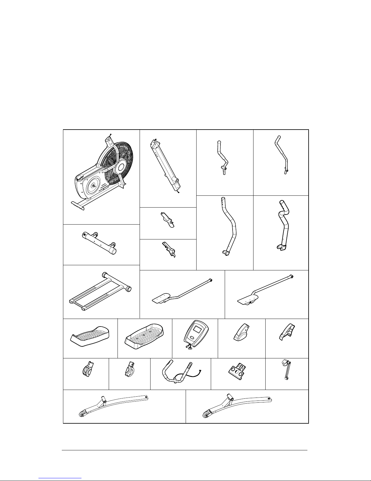
Components - Parts
Note: Some of the smaller components may be pre-fitted to larger components.
Please check carefully before contacting Argos regarding any missing components.
Please check you have all the parts listed below
No.1 Main Frame x 1pc
No.2 Front Post x 1pc
No.3L
Handlebar x 1pc
No.3R
Handlebar x 1pc
L
No.9 Front Stabilizer x 1pc
No.11F
Decoration Cover x 2pc
No.11R
Decoration Cover x 2pc
No.13R
Pivoting Arm x 1pc
No.13L
Pivoting Armx 1pc
No.14 Rear Base x 1pc
No.15L Pedal Linkage x 1pc
No.15R Pedal Linkage x 1pc
No.19R Pedal x 1pc
No.19L Pedal x 1pc
No.101R
Roller Cover x 2p
c
No.101L
Roller Cover x 2pc
No.102F
Joint Cover x 1pc
No.102R
Joint Cover x 1pc
No.119 Pedal Arm Assembly x 1pc
No.120 Pedal Arm Assembly x 1pc
No.21 Monitor x 1pc
No.115 Handlebar x 1pc
No.117 Ipad Holder x 1pc
No.10 Crank with
Connector
x 2pc
3
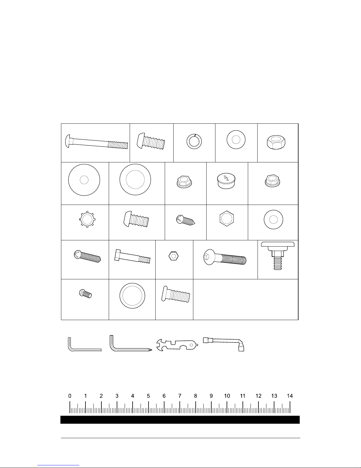
Components - Fixings
Please check you have all the fixings listed below
Ruler - Use this ruler to help correctly identify the hardware
No.75 M6 Nut x 4pcs
No.107 ø20 x 26 x 0.5T
Wave Washer x 2pcs
No.42 ø19xø8.5x1.5T
Flat Washer x 4pcs
No.46 ø38xø8.5x2.0T
Flat Washer x 2pcs
No.47 ø38xø19x0.5T
Flat Washer x 2pcs
No.53 ø10 Tooth Lock
Washer x 2p
cs
No.64 ø19xø8.5x1.5T Arc
Washer x 10pcs
No.74 M6x35mm
Hex Head Bolt x 4pcs
No.71 M4x25mm Round
Head Screw x 4pcs
nottuB mm51x5M 16.oN
Head Screw x 8pcs
No.112 M8x18mm
Button Head Bolt x 4pcs
No.55 M8x15mm Button
Head Bolt x 6pcs
No.40 M8x20mm Button
Head Bolt x 18pcs
No.39 M8x75mm Carriage Bolt x 4pcs
No.52 M10x1.25Px7H
Right Flange Nut x 1pc
No.48 M10x1.25Px7H
Left Flange Nut x 1pc
No.89 M8x48mm Button Head Bolt x 2pcs
No.109 M5x15mm
Round Head Bolt x 4pcs
No.41 M8 Spring Washer
x 14pcs
No.92 M8x24mm
Adjustable Knob x 2pcs
No.43 M8 Nut x 2pcs
No.63
M8 Acorn Nut x 4pc
s
No.51 Crank Cover x
2pcs
Fixing Tools
Allen Wrench (M5) x 2pcs Allen Wrench (M6) x 2pcs Universal Wrench x 1pc L Type Wrench x 1pc
Note: Some of the fixings are pre-fitted to the larger components. Please check
carefully before contacting Argos regarding any missing fixings.
1
39
64
63
41
9
L
4
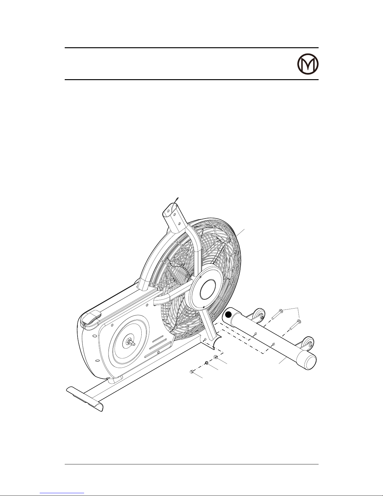
Assembly Instructions
STEP 1
Note: There is an “L” decal on the front stabiizer (9).
Attach (with the “L” decal on the left side) front stabiliser (9) to main frame (1),
using 2 sets of carriage bolts (39), acorn nuts (63), spring washers (41) and arc
washers (64).
5
Assembly Instructions
STEP 2
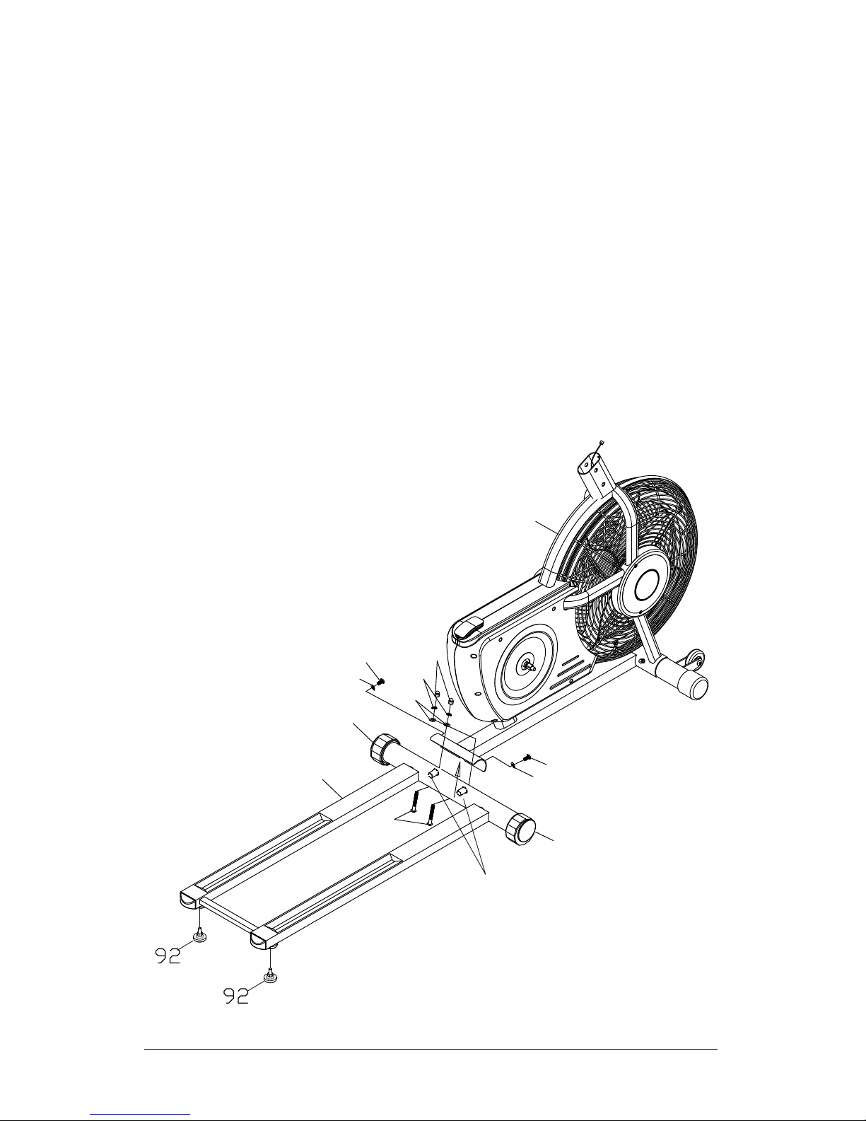
a. Attach 2 x stands (92) to the bottom of rear base (14).
b. Make sure the grooves on the rear base (14) are on top as shown. Attach rear
base (14) to main frame (1), using 2 sets of carriage bolts (39), acorn nuts (63),
spring washers (41), arc washers (64), allen head bolt (40) and arc washer (64) .
Important note: Adjust 2 x leveling caps (28) and stands (92) on rear base
(14) to ensure the elliptical is stable.
39
64
41
63
14
114
1
64
40
40
64
28
28

6
Assembly Instructions
STEP 3
Connect middle section connection wire (81) with sensor wire (60).
Attach front post (2) to main frame (1) using 6 x button head bolts (40), 6 x
washers (64) are applied at the front (curved area) of post.
2
115
116
64
41
40
1
40
41
41
41
41
42
42
40
40
64
81
81
60
Auxiliary wire helps hand
pulse wire (116) to thread
the holes of front post (2)
and discard it after finish.

40
40
61
61
101R
101L
113
101L
101R
103
103
107
61
15L
15R
119
89
104
10
43
89
10
104
43
120
107
61
113
7
Assembly Instructions
STEP 4
There is an “L” decal on the left pedal linkage (15L), and an “R” decal on the right
pedal linkage (15R). Refer to right and left pedal arm (78) assembly view for the
following assembly.
a. Attach pedal arm sub assy (119) to the left pedal linkage (15L) with support
plate (103), 1 x wave washer (107) and 3 x button head bolts (40). Repeat same
procedure for right side assembly.
b. Attach roller covers (101L, 101R) to pedal arm assy’s (119/120) using 4 x round
head screws (61) for each assembly.
c. Attach crank connector (104) to pedal arm sub assy (119) using (89) button head
bolt and (43) at washer. Repeat same procedure for right side assembly.

Arrow Mark
51
10
52
53
White Mark
17
RIGHT SIDE
White Mark
LEFT SIDE
Arrow Mark
51
10
48
53
17
1
a.
b.
51
TOOL
78
10
52
53
17
A.
B.
C.
8
Assembly Instructions
STEP 5
When attaching cranks ensure pedal arm rollers (113) run in
grooves on rear base (14).
a. Align arrow mark on crank to white mark on right axle secure
crank (10) with washer (53) and ange nut (52), tighten with
socket wrench & fit cap (51) to crank (10).
The right ange nut (52), black colour, has right hand thread and
is tightened by turning clockwise.
b. Align arrow mark on crank to white mark on left axle secure
crank (10) with washer (53) and ange nut (48), tighten with
socket wrench & attach cap (51) to crank (10).
The left ange nut (48), brass colour, has a left hand thread and
is tightened by turning anti-clockwise.
Important note
• It is possible to assemble the cranks (10) in the wrong
position as shown in inset drawings A and B. Once
assembled they will require a special tool (not provided) to
remove. Read & understand the assembly instructions before
attaching.
Important:
Flange nut on left side only
tightens anti-clockwise.

47
109
13L
13R
74
46
46
3R
12
47
71
75
74
41
41
40
40
75
3L
71
109
109
109
102F
112
112
112
112
11R
11R
111
111
11F
11F
102R
102R
102F
15L
15R
9
Assembly Instruction
STEP 6
a. There is an “L” decal on left headlebar (3L) and an “R” decal on right handlebar (3R).
Insert left and right handlebars (3L, 3R) into the left and right pivoting arms (13L,
13R) and secure with hex bolts (74) and nuts (75).
Note: The hex bolts (74) must fit inside the hex-shaped holes to properly secure.
b. Slide the left pivoting arm/left handlebar (13L, 3L) onto the left side of shaft (12)
and secure with washer (47), a large washer (46), spring washer (41) and button
head bolt (40). Repeat for right side.
b. Slide covers (102R) onto pedal linkages.
c. Attach the lower end of the left pivoting arms (13L & 13R) to the pedal linkages
(15L & 15R) with button head bolts (112).
d. Attach joint covers (102F & 102 R) to pivoting arms (13L & 13R) and secure with
button head bolts (109).

AA Batteries
21
21
2
117
118
81
20
116
10
Assembly Instruction
STEP 7
a. Ipad holder assembly
Thread the cables of moniter through the square hole of IPAD holder (117).
Attach iPad holder (117) to the rear of monitor (21) and tighten with 2 x bolts
(118).
Warning Instructing:
1. The manufacturer accepts no responsibility for damage caused to devices
during the use of this equipment.
2. Vigorous exercise could cause the iDevice to rock out of its holder and
therefore extra care should be taken to ensure it is securely mounted at all
times.
3. Please ensure that this exercise equipment is on a flat and level surface and
is levelled correctly.
4. We recommend the use of an anti-vibration/sports equipment mat with this
product.
b. Install 2 x AA batteries (not supplied) into the monitor (21). See illustration for
correct battery orientation. Connect middle section cables (81) to moniter
cables (21) pushing excess cable back into the front post (2). Attach the monitor
(21) with ipad holder to the mount plate with round head screws (20).
Note: Avoid trapping the wires.

15L
19L
55
119
19R
15R
11
Assembly Instruction
Step 8
Attach pedals (19L & 19R) to pedal
linkages (15L & 15R) with 3 x button
head bolts (55) per pedal.
Fit with open edge to outside.
3
7
1
28
14
92
12
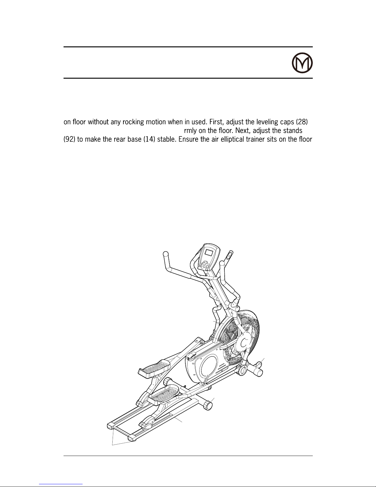
Set Up Instructions
Leveling: There are four points where you can adjust the air elliptical trainer so it sits
so that main frame (1) is stable and sits fi
without rocking.
Moving: The air elliptical trainer has a pair of wheels on the front stabilizer (37).
Raise the back end of the rear base (14) to move.
Function inspection:
Visually inspect the air elliptical trainer to verify that assembly is as shown in the
illustration. Check the function of elliptical, stand on the foot pedals (19R,19L) and
place your hands at a comfortable position on the handlebars. Slowly move your
highest foot forward and follow the natural path of the machine. Turn the crank slowly
through one complete revolution to verify that the drive train functions properly.

13
Monitor Instruction
Power On Pedal movement or press the MODE button.
Power Off
Automatic shut off after four minutes of
inactivity.
Computer Instruction
FUNCTION BUTTON
MODE Press it to select function between time, distance, calories and pulse.
RESET
Press it to reset the function value of time, distance, calories and pulse.
Press and hold for 4 seconds to reset all functions value.
Press it to increase the target value of time, distance, calorie and pulse.
Press it to decrease the target value of time, distance, calorie and pulse.
FUNCTIONS
SCAN
Automatically scans through the function of TIME, SPEED, DISTANCE,
CALORIES and PULSE in sequence with change every four seconds.
Press and release the button until “SCAN” appears on the display.
TIME
Displays the time from one second up to 99:59 minutes. Count down
from your preset target time to 00:00 during your workout.
SPEED Display the current speed from zero to 999.9 kilometer per hour.
DISTANCE Displays the distance from zero to 99.99 kilometer.
CALORIES
Display the calorie consumption from zero to 999.9 Kcal.
The calorie readout is an estimate for an average user.
This should be used only as a comparison between workouts on this unit.
PULSE
The monitor will display the user’s current heart rate in beats per minute
during your workout. Both hands must hold the hand pulse for a heart
rate reading during your workout.
NOTE: The Monitor will shut off automatically after four minutes of inactivity. All
function values will be kept. Press the RESET button and hold it down for four
seconds to reset all function values to zero.
Note: When using the Bluetooth facility, this computer needs to be in operation, as
the Bluetooth chipset is built in and powered from its batteries.

AA Batteries
14
Monitor Instruction
How To Install and Replace Batteries
a. Open the battery compartment on the back of the
monitor (21).
b. The monitor (21) operates with 2 x AA batteries, the
batteries are not included. Refer to the illustration for
correct orientation.
NOTE:
1. Do not mix a new battery with an old battery.
2. Use the same type of battery. Do not use an alkaline
battery with another type of battery.
3. Rechargeable batteries are not recommended.

15
The safety and integrity designed into the Elliptical can only be maintained when the
Elliptical is regularly examined for damage and wear. Special attention should be
given to the following.
1. Verify that all nuts and bolts are present and properly tightened. Replace missing
nuts and bolts. Tighten loose nuts and bolts.
2. It is the sole responsibility of the user/owner to ensure that regular maintenance is
performed.
3. Worn or damaged components shall be replaced immediately or the Elliptical
removed from service until repair is made.
4. Only genuine components shall be used to maintain /repair the Elliptical.
5. Keep your Elliptical clean by wiping it off with an absorbent cloth after use.
Information for Users on Disposal of old Equipment and Batteries
These symbols indicate that equipment with these symbols should not be disposed
of as general household waste. If you want to dispose of the product or battery,
please consider the collection systems or facilities for appropriate recycling.
Notice: The sign Pb below the symbol for batteries indicates that this battery
contains lead.
Care and Maintainence
Products
Battery

80
100
120
140
160
180
200
Beats per minute (bpm)
25
Age
30 35 40 45 50 55 60 70
Cardiovascular
performance
Intermediate aerobic
Effective fat burning
Up to 55%
55% to 65%
65% to 85%
85% to Max
16
Exercising Information
Before starting to exercise
How you begin your exercise program depends on your physical condition. If you
have been inactive for several years, or are severely overweight, you must start
slowly and increase your time on the equipment; a few minutes per workout.
Initially, you may be able to exercise only for a few minutes in your target zone,
however, your aerobic fitness will improve over the next six to eight weeks. Don’t be
discouraged if it takes longer. It’s important to work at your own pace. Ultimately,
you’ll be able to exercise continuously for 30 minutes. The better your aerobic
fitness, the harder you will have to work to stay in your target zone.
Please remember these essentials:
• Have your doctor review your training and diet programs to advise you of a
workout routine you should adopt.
• Begin your training program slowly with realistic goals that have been set by you
and your doctor.
• Monitor your pulse frequently. Establish your target heart rate based on your age
and condition.
• Set up your equipment on a at even surface at least 3 feet from walls and
furniture.
Exercise intensity
To maximize the benefits of exercising, it is important to exercise with the proper
intensity. The proper intensity level can be found by using your heart rate as a
guide. For effective aerobic exercise, your heart rate should be maintained at a level
between 65% and 85% of your maximum heart rate as you exercise. This is known as
your target zone. You can find your target zone in the table below.

17
During the first few months of your exercise program, keep your heart rate near the
low end of your target zone as you exercise. After a few months, your heart rate can
be increased gradually until it is near the middle of your target zone as you exercise.
To measure your heart rate, stop exercising but continue moving your legs or
walking around and place two fingers on your wrist.
Take a six-second heartbeat count and multiply the
results by 10 to find your heart rate. For example,
if your six-second heartbeat count is 14, your heart
rate is 140 beats per minute. (A six-seconds count
is used because your heart rate will drop rapidly
when you stop exercising.) Adjust the intensity of
your exercise until your heart rate is at the proper
level.
Exercising Information
Aerobic Exercise
Aerobic exercise improves the fitness of your lungs and heart - your body’s most
important muscle. Aerobic exercise fitness is promoted by any activity that uses your
large muscles (arms, legs, or buttock, for example). Your heart beats quickly and you
breathe deeply. An aerobic exercise should be part of your entire exercise routine.
Weight Training
Along with aerobic exercising which helps get rid of and keep off the excess fat
that our bodies can store, weight training is an essential part of the exercise routine
process. Weight training helps tone, build and strengthen muscle. If you are working
above your target zone, you may want to do a lesser amount of reps. As always,
consult your doctor before beginning any exercise program.

18
Suggested Stretches
The correct form for several basic stretches is shown at the right. Move slowly as
you stretch, never bounce.
1. Toe touch stretch
Stand with your knees bent slightly and
slowly bend forward from your hips. Allow
your back and shoulders to relax as you
reach down toward your toes as far as
possible. Hold for 15 counts, then relax.
Repeat 3 times.
2. Hamstring Stretch
Sit with one leg extended. Bring the sole
of the opposite foot toward you and rest it
against the inner thigh of your extended leg.
Reach toward your toes as far as possible.
Hold for 15 counts, then relax. Repeat 3
times for each leg. Stretches: Hamstrings,
lower back and groin.
Exercising Information

19
3. Calf/Achilles Stretch
With one leg in front of the other, reach forward and
place your hands against a wall. Keep your back leg
straight and your back foot at on the oor Bend your
front leg, lean forward and move your hips toward
the wall. Hold for 15 counts, then relax. Repeat 3
times for each leg. To cause further stretching of
the Achilles tendons, bend your back leg as well.
Stretches: Calves, Achilles tendons and ankles.
4. Quadriceps Stretch
With one hand against a wall for balance, reach back
and grasp one foot with your other hand. Bring your
heel as close to your buttocks as possible. Hold for
15 counts, then relax. Repeat 3 times for each leg.
Stretches: Quadriceps and hip muscles.
5. Inner Thigh Stretch
Sit with the soles of your feet together and your
knees outward. Pull your feet toward your groin area
as far as possible. Hold for 15 counts, then relax.
Repeat 3 times.
Exercising Information

20
Exploded Diagram

21
Parts List
No. Description Q’ty No. Description Q’ty
1 Main Frame 1 32 Nut (M5) 7
2 Front Post 1 33 Flat Head Screw (M5x20L) 7
3 R/L Handlebar (Right/Left) 1 pair 34 Belt Adjuster 2
4 R/L Fan Cage (Right/Left) 1 pair 35 Fan Axle 1
5 Trim Strap 1 36 Button Head Bolt (M8x38L) 2
6 R/L Fan Cage Cover (Right/Left) 1 pair 37 Wheel 2
7 R/L Fan Wheel (Right/Left) 1 pair 38 Nut (M10x9H)
3
8 Axle Holder 1 39 Carriage Bolt (M8x75L)
4
9 Front Stabilizer 1 40 Button Head Bolt (M8x20L)
18
10 Crank 2 41 Spring Washer (M8)
14
11 F/R Decoration Cover (Front/Rear) 2 pairs 42 Flat Washer (ø19xø8.5x1.5T)
4
12 Pivot Shaft 1 43 Nut (M8)
2
13 R/L Pivoting Arm (Right/Left) 1 pair 44 Flat Washer (ø32xø8.4x2.0T) 4
14 Rear Base 1 45 Cap (ø25.4) 2
15 R/L Pedal Linkage (Right/Left) 1 pair 46 Flat Washer (ø38xø8.5x2.0T) 2
16 Foam Grip 2 47 Flat Washer (ø38xø19x0.5T) 2
17 Belt Pulley W/Axle 1 48 Left Flange Nut (M10x1.25Px7H) 1
18 R/L Cover (Right/Left) 1 pair 49 Crank Cover 2
19 R/L Foot Pedal (Right/Left) 1 pair 50 Sensor Plate 2
20 Button Head Bolt (M5x12L) 4 51 Crank Cap 2
21 Monitor 1 52 Right Flange Nut (M10x1.25Px7H) 1
22 Round End Cap (ø60) 2 53 Tooth Lock Washer (ø10) 2
23 Powder Bush 4 54 Handlebar Foam Grip 2
24 Idler Wheel Bracket 1 55 Button Head Bolt (M8x15L) 6
25 Idler Wheel 1 56 Clip (ø17) 2
26 Tension Spring (ø2.3xø14x60L) 1 57 Adjustable Washer (ø22xø17x0.5T) 3
27 Drive Belt 1 58 Bearing 2
28 Adjustable End Cap (3in1) 2 59 Clip (ø35) 2
29 Dome Plug (ø50xø29) 2 60 Sensor w/Wire 1
30 Button Head Screw (M4x12L) 2 61 Button Head Screw (M5x15L) 8
31 Button Head Screw (M5x10L)
2 62
Sensor Holder
1

22
Parts List
No. Description Q’ty No. Description Q’ty
63 Acorn Nut (M8) 4 94 Pivoting Arm Space (ø38) 6
64 Arc Washer (ø19xø8.5x1.5T)
10
95 Nut (3/8”x26Wx5H) 1
65 Allen Head Bolt (M10x25L) 1 96 Button Head Screw (M4x20L) 7
66 Allen Head Bolt (M10x35L) 1 97 Sleeve 2
67 Spacer (ø16xø10x10H) 1 98 Balance Bar 7
68 Flat Washer (ø32xø16x0.5T) 3 99 Short Roller Spacer (ø14xø10.5x8.3H) 2
69 Wave Washer (ø13xø10x0.4T) 1 100 Spacer (ø14xø10.5x9.2H) 4
70 Foam 4 101 R/L Roller Cover (Right/Left) 2 pairs
71 Round Head Screw (M4x25L) 4 102 F/R Joint Cover (Front/Rear) 2 pairs
72 Flat Washer (ø13xø10x0.5T) 2 103 Support Plate 2
73 Bearing 4 104 Pedal Arm Welded Connector 2
74 Hex Head Bolt (M6x35L) 4 105 Connector Bushing (ø32xø28xø16x14H) 8
75 Nut (M6) 4 106 Linkage Connector 2
76 Button Head Screw (M4x15L) 10 107 Wave Washer (ø20xø26x0.5T) 2
77 Button Head Screw (M4x25L) 4 108 Nut (M8) 2
78 Pedal Arm 2 109 Round Head Screw (M5x15L) 4
79 Nut (3/8”x26Wx9H) 2 110 Oval Cap (40x80) 1
80 Nut (3/8”x26Wx7H) 2 111 Shaft Cap 2
81 Middle Section Sensor Wire 1 112 Button Head Bolt (M8x18L) 4
82 Button Head Bolt (M6x43L) 4 113 Roller (ø20x24H) 2
83 Nut (M6) 4
115 Handlebar 184 Spacer (ø16xø10x13.5H) 1
116 Hand Pulse Wire 185 Round Head Screw (M4x50L) 1
117 Ipad Holder 186 Nut (M4x5H) 1
118 Flat Head Bolt 287 Magnet (ø15x6.5H) 1
119 Pedal Arm Assembly (left) 188 Cap (30x60) 2
120 Pedal Arm Assembly (right) 189 Button Head Bolt (M8x48L) 2
Tool Universal Wrench 190 Powder Bush (ø10xø8.2X7H) 4
Tool L Type Wrench 191 Bearing 2
Tool L Type Allen Head Wrench (M5) 292 Adjustable Knob (M8x24L) 2
Tool L Type Allen Head Wrench (M6) 2
93 Button Head Bolt (M10x60L) 2
114
Nut (M8)
2

Guarantee
Product Guarantee
This product is guaranteed against manufacturing defects for a period of
Year
This product is guaranteed for twelve months from the date of original purchase. Any
defect that arises due to faulty materials or workmanship will either be replaced,
refunded or repaired free of charge where possible during this period by the dealer
from whom you purchased the unit.
The guarantee is subject to the following provisions:
The guarantee does not cover accidental damage, misuse, cabinet parts, knobs or
consumable items.
The product must be correctly installed and operated in accordance with the
instructions contained in this manual.
It must be used solely for domestic purpose.
The guarantee will be rendered in invalided if the product is re-sold or has been
damaged by inexpert repairs.
Specifications are subject to change without notice.
The manufacture disclaims any liability for the incidental or consequential damages.
The guarantee is in addition to, and does not diminish your statutory or legal rights.
In the event of a problem with the products with in the guarantee period call the
Customer Helpline: 08456 000 464.
Guarantor: Argos Ltd
489-499 Avebury Boulevard
Central Milton Keynes
MK9 2NW
 Loading...